EP2482420A2 - Power flow regulator including a plurality of DC-DC converters - Google Patents
Power flow regulator including a plurality of DC-DC converters Download PDFInfo
- Publication number
- EP2482420A2 EP2482420A2 EP20120000551 EP12000551A EP2482420A2 EP 2482420 A2 EP2482420 A2 EP 2482420A2 EP 20120000551 EP20120000551 EP 20120000551 EP 12000551 A EP12000551 A EP 12000551A EP 2482420 A2 EP2482420 A2 EP 2482420A2
- Authority
- EP
- European Patent Office
- Prior art keywords
- converters
- output
- directional
- electrically connected
- input
- Prior art date
- Legal status (The legal status is an assumption and is not a legal conclusion. Google has not performed a legal analysis and makes no representation as to the accuracy of the status listed.)
- Withdrawn
Links
Images




Classifications
-
- H—ELECTRICITY
- H02—GENERATION; CONVERSION OR DISTRIBUTION OF ELECTRIC POWER
- H02J—ELECTRIC POWER NETWORKS; CIRCUIT ARRANGEMENTS OR SYSTEMS FOR SUPPLYING OR DISTRIBUTING ELECTRIC POWER; SYSTEMS FOR STORING ELECTRIC ENERGY
- H02J1/00—Circuit arrangements for DC mains or DC distribution networks
- H02J1/10—Parallel operation of DC sources
- H02J1/102—Parallel operation of DC sources being switching converters
-
- H—ELECTRICITY
- H02—GENERATION; CONVERSION OR DISTRIBUTION OF ELECTRIC POWER
- H02J—ELECTRIC POWER NETWORKS; CIRCUIT ARRANGEMENTS OR SYSTEMS FOR SUPPLYING OR DISTRIBUTING ELECTRIC POWER; SYSTEMS FOR STORING ELECTRIC ENERGY
- H02J3/00—Circuit arrangements for AC mains or AC distribution networks
- H02J3/38—Arrangements for feeding a single network from two or more generators or sources in parallel; Arrangements for feeding already energised networks from additional generators or sources in parallel
- H02J3/46—Controlling the sharing of generated power between the generators, sources or networks
-
- H—ELECTRICITY
- H02—GENERATION; CONVERSION OR DISTRIBUTION OF ELECTRIC POWER
- H02J—ELECTRIC POWER NETWORKS; CIRCUIT ARRANGEMENTS OR SYSTEMS FOR SUPPLYING OR DISTRIBUTING ELECTRIC POWER; SYSTEMS FOR STORING ELECTRIC ENERGY
- H02J2101/00—Supply or distribution of decentralised, dispersed or local electric power generation
- H02J2101/20—Dispersed power generation using renewable energy sources
- H02J2101/22—Solar energy
- H02J2101/24—Photovoltaics
- H02J2101/25—Photovoltaics involving maximum power point tracking control for photovoltaic sources
-
- H—ELECTRICITY
- H02—GENERATION; CONVERSION OR DISTRIBUTION OF ELECTRIC POWER
- H02J—ELECTRIC POWER NETWORKS; CIRCUIT ARRANGEMENTS OR SYSTEMS FOR SUPPLYING OR DISTRIBUTING ELECTRIC POWER; SYSTEMS FOR STORING ELECTRIC ENERGY
- H02J3/00—Circuit arrangements for AC mains or AC distribution networks
- H02J3/38—Arrangements for feeding a single network from two or more generators or sources in parallel; Arrangements for feeding already energised networks from additional generators or sources in parallel
- H02J3/381—Dispersed generators
-
- Y—GENERAL TAGGING OF NEW TECHNOLOGICAL DEVELOPMENTS; GENERAL TAGGING OF CROSS-SECTIONAL TECHNOLOGIES SPANNING OVER SEVERAL SECTIONS OF THE IPC; TECHNICAL SUBJECTS COVERED BY FORMER USPC CROSS-REFERENCE ART COLLECTIONS [XRACs] AND DIGESTS
- Y02—TECHNOLOGIES OR APPLICATIONS FOR MITIGATION OR ADAPTATION AGAINST CLIMATE CHANGE
- Y02E—REDUCTION OF GREENHOUSE GAS [GHG] EMISSIONS, RELATED TO ENERGY GENERATION, TRANSMISSION OR DISTRIBUTION
- Y02E10/00—Energy generation through renewable energy sources
- Y02E10/50—Photovoltaic [PV] energy
- Y02E10/56—Power conversion systems, e.g. maximum power point trackers
Definitions
- the disclosed concept pertains generally to direct current power sources and loads, and, more particularly, to power flow regulators for direct current power sources and loads.
- multiple parallel connected DC sources 2,4,6 are used to supply a DC load 8.
- One example of such a system is multiple DC solar strings supplying one DC load or supplying a DC link of a solar inverter.
- one DC source 10 can supply multiple DC loads 12,14,16 as shown in Figure 2 .
- One example is that one DC source can charge multiple parallel connected batteries.
- multiple DC sources 18,20,22 can supply multiple DC loads 24,26,28 as shown in Figure 3 .
- a DC source's output power is determined by its DC voltage, such as the voltage of a solar panel (string).
- the source voltages of the DC sources 2,4,6 are always equal to the load voltage of the DC load 8.
- the output power of the individual DC sources 2,4,6 is determined by the DC load voltage. It is impossible to change DC power distribution among the DC sources 2,4,6 since this is solely determined by load voltage.
- a DC load's power is determined by its DC voltage.
- the load voltages of the DC loads 12,14,16 are always equal to the source voltage of the DC source 10.
- the consumed power of the individual DC loads 12,14,16 is determined by the DC source voltage. It is impossible to change DC power distribution among the DC loads 12,14,16 since this is solely determined by source voltage.
- a power flow regulator comprises: a plurality of bi-directional DC-DC converters, each of the converters comprising a first input, a second input, a first output and a second output; and a capacitor electrically connected between the first and second inputs of each of the converters, wherein either: the first output of each of the converters is electrically connected to a corresponding DC source and the second output of each of the converters is electrically connected to a common DC load, or the first output of each of the converters is electrically connected to a corresponding DC load and the second output of each of the converters is electrically connected to a common DC source.
- the plurality of bi-directional DC-DC converters may be a first plurality of bi-directional DC-DC converters; the capacitor may be a first capacitor; and the common DC load may comprise: a second plurality of bi-directional DC-DC converters, each of the second plurality of bi-directional DC-DC converters may comprise a first input, a second input, a first output and a second output; and a second capacitor electrically connected between the first and second inputs of each of the second plurality of bi-directional DC-DC converters, wherein the first output of each of the second plurality of bi-directional DC-DC converters may be electrically connected to the second output of each of the first plurality of bi-directional DC-DC converters, and wherein the second output of each of the second plurality of bi-directional DC-DC converters may be electrically connected to a corresponding DC load.
- the plurality of bi-directional DC-DC converters may be a first plurality of bi-directional DC-DC converters; the capacitor may be a first capacitor; and the common DC source may comprise: a second plurality of bi-directional DC-DC converters, each of the second plurality of bi-directional DC-DC converters may comprise a first input, a second input, a first output and a second output; and a second capacitor electrically connected between the first and second inputs of each of the second plurality of bi-directional DC-DC converters, wherein the first output of each of the second plurality of bi-directional DC-DC converters may be electrically connected to a corresponding DC source, and wherein the second output of each of the second plurality of bi-directional DC-DC converters may be electrically connected to the first output of each of the first plurality of bi-directional DC-DC converters.
- a power flow regulator comprises: a plurality of mono-directional DC-DC converters, each of the converters comprising a first input, a second input, a first output and a second output; and a capacitor electrically connected between the first and second inputs of each of the converters, wherein either: the first output of each of the converters is electrically connected to a corresponding DC source having a common ground, the second output is electrically connected to the second input of each of the converters, and a common DC load is electrically connected between the first input of each of the converters and the common ground, or the second output of each of the converters is electrically connected to a corresponding DC load having a common ground, the first output is electrically connected to the second input of each of the converters, and a common DC source is electrically connected between the first input of each of the converters and the common ground.
- the plurality of mono-directional DC-DC converters may be a first plurality of mono-directional DC-DC converters; the capacitor may be a first capacitor; and the common DC load may comprise: a second plurality of mono-directional DC-DC converters, each of the second plurality of mono-directional DC-DC converters may comprise a first input, a second input, a first output and a second output; and a second capacitor electrically connected between the first and second inputs of each of the second plurality of mono-directional DC-DC converters, wherein the first input of each of the second plurality of mono-directional DC-DC converters may be electrically connected to the first input of each of the first plurality of mono-directional DC-DC converters, wherein the first output of each of the second plurality of mono-directional DC-DC converters may be electrically connected to the second input of each of the second plurality of mono-directional DC-DC converters, and wherein the second output of each of the second plurality of mono-directional DC-DC converters may be electrically connected to a
- the plurality of mono-directional DC-DC converters may be a first plurality of mono-directional DC-DC converters; the capacitor may be a first capacitor; and the common DC source may comprise: a second plurality of mono-directional DC-DC converters, each of the second plurality of mono-directional DC-DC converters may comprise a first input, a second input, a first output and a second output; and a second capacitor electrically connected between the first and second inputs of each of the second plurality of mono-directional DC-DC converters, wherein the first input of each of the second plurality of mono-directional DC-DC converters may be electrically connected to the first input of each of the first plurality of mono-directional DC-DC converters, wherein the first output of each of the second plurality of mono-directional DC-DC converters may be electrically connected to a corresponding DC source, and wherein the second output of each of the second plurality of mono-directional DC-DC converters may be electrically connected to the second input of each of the second plurality of mono-directional DC
- number shall mean one or an integer greater than one ( i.e ., a plurality).
- DC-to-DC converter (or “DC-DC converter”) shall mean a circuit that converts a source of direct current (DC) from one voltage level to another voltage level.
- bi-directional DC-to-DC converter shall mean a DC-to-DC converter (or DC-DC converter) that can move power in either direction (e.g., from its input to its output, and from its output to its input).
- DC-to-DC converter (or “mono-directional DC-DC converter”) shall mean a DC-to-DC converter (or DC-DC converter) that can move power in one direction (e.g., either from its input to its output, or from its output to its input).
- bi-directional delta DC-DC converter shall mean a bi-directional DC-to-DC converter (or bi-directional DC-DC converter) that, for example, if the bi-directional delta DC-DC converter directly supplies a DC load, then the DC voltage of the DC load is the corresponding DC source voltage plus or minus the output voltage of the converter, or, for example, if the bi-directional delta DC-DC converter directly supplies a corresponding DC load, then the DC voltage of the corresponding DC load is the DC source voltage plus or minus the output voltage of the converter.
- the term "mono-directional delta DC-DC converter” shall mean a mono-directional DC-to-DC converter (or mono-directional DC-DC converter) that, for example, if the mono-directional delta DC-DC converter directly supplies a DC load, then the DC voltage of the DC load is the corresponding DC source voltage plus or minus the output voltage of the converter, or, for example, if the mono-directional delta DC-DC converter directly supplies a corresponding DC load, then the DC voltage of the corresponding DC load is the DC source voltage plus or minus the output voltage of the converter.
- the disclosed concept is applicable to a wide range of power flow regulators including a plurality of delta DC-DC converters.
- delta DC-DC converters 30,32,34 with a bi-directional output voltage are employed for multiple parallel connected DC sources 36,38,40 to supply a DC load 42.
- a DC load 42 As employed in connection with Figure 4 :
- PS f ⁇ VL - VO
- the output power of individual DC sources 36,38,40 can be regulated by controlling the output voltage of the delta DC-DC converters 30,32,34, VO.
- each delta DC-DC converter is 100%.
- PO PI.
- the typical efficiency of the delta DC-DC converters 30,32,34 is about 89% to about 95%. There is no impact to the overall analysis when the efficiency is less than 100%.
- a bi-directional output voltage DC-DC converter (or bi-directional DC-DC converter) is a known device.
- the DC-DC converter has an input 44,46 in which the voltage is mono-directional and the current is bi-directional, and an output 48,50 in which the voltage is bi-directional and the current is mono-directional.
- the DC-DC converter is bi-directional.
- the DC source output power of a DC source can be regulated by the output voltage of the delta DC-DC converter (e.g., 30, 32 or 34). All inputs 44,46 of the delta DC-DC converters 30,32,34 are connected to the common DC capacitor 52 without additional DC sources. Also, additional power sources or loads (not shown) might be connected in parallel to the DC capacitor 52 in Figure 4 . Thus, the energy drawn from the system could supply an external load (not shown), or external power sources (not shown) can inject the energy to the system.
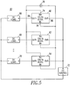
- delta DC-DC converters 60,62,64 with a bi-directional output voltage are employed for multiple parallel connected DC loads 66,68,70 supplied by a DC source 72. If the consumed power of the DC loads 66,68,70 is determined by the DC voltage, then the DC load power consumption can be regulated by the output voltage of each delta DC-DC converter 60,62,64. All inputs 74,76 of the delta DC-DC converters 60,62,64 are connected to a common DC capacitor 78 without additional DC sources. Also, additional power sources or loads (not shown) might be connected in parallel to the DC capacitor 78 in Figure 5 . Thus, the energy drawn from the system could supply an external load (not shown), or external power sources (not shown) can inject the energy to the system.
- each of the respective power flow regulators 80;82 includes a plurality of bi-directional delta DC-DC converters 30,32,34;60,62,64 each of which includes a first input 44;74, a second input 46;76, a first output 48;84 and a second output 50;86, respectively.
- the capacitor 52;78 is electrically connected between the first and second inputs 44,46;74,76 of each of the converters 30,32,34;60,62,64, respectively.
- the first output 48 of each of the converters 30,32,34 is electrically connected to the corresponding DC source 36,38,40 and the second output 50 of each of the converters 30,32,34 is electrically connected to the common DC load 42.
- the first output 84 of each of the converters 60,62,64 is electrically connected to the corresponding DC load 66,68,70 and the second output 86 of each of the converters 60,62,64 is electrically connected to the common DC source 72.
- the bi-directional delta DC-DC converters 30,32,34;60,62,64 have galvanic isolation between the first and second outputs 48,50;84,86 and the first and second inputs 44,46;74,76, respectively.
- the bi-directional delta DC-DC converters 30,32,34;60,62,64 have no galvanic isolation between the first and second outputs 48,50;84,86 and the first and second inputs 44,46;74,76, respectively.
- a positive voltage is between the first and second outputs 48,50;84,86 of a number of the bi-directional delta DC-DC converters 30,32,34;60,62,64, respectively.
- the output voltage of each converter 30,32,34;60,62,64 cannot always be positive; a number of output voltages are positive and a number of output voltages are negative.
- a negative voltage is between the first and second outputs 48,50;84,86 of a number of the bi-directional delta DC-DC converters 30,32,34;60,62,64, respectively.
- a positive constant DC voltage is across the capacitor 52,78 between the first and second inputs 44,46;74,76 of each of the bi-directional delta DC-DC converters 30,32,34;60,62,64, respectively.
- DC-DC converters 90,91,92,93,94,95 with a bi-directional output voltage are employed for multiple parallel connected DC sources 96,98,100 to supply multiple DC loads 102,104,106, as will be discussed. If the output power of the DC source 96,98,100 is determined by its DC voltage, then the DC source output power can be regulated by the output voltage of the delta DC-DC converters 90,92,94. All inputs 108,110 of the delta DC-DC converters 90,92,94 are connected to a common DC capacitor 112 without additional DC sources (not shown).
- the DC load power consumption can be regulated by the output voltage of the delta DC-DC converters 91,93,95. All inputs 114,116 of the delta DC-DC converters 91,93,95 are connected to a common DC capacitor 118 without additional DC sources (not shown). Also, additional power sources or loads (not shown) might be connected in parallel to the DC capacitors 112,118 in Figure 6 . Thus, the energy drawn from the system could supply an external load (not shown), or external power sources (not shown) can inject the energy to the system.
- a delta DC-DC converter with bi-directional output voltage has the following characteristics: (1) the input and output can employ galvanic isolation or not, although galvanic isolation is preferred; (2) the input is a positive constant voltage; and (3) the output voltage can be positive or negative.
- capacitor voltage will be kept constant. If it is not 0 W, and is, for example, 1 W, then the capacitor voltage will increase.
- the output voltages of the delta DC-DC converters 90,92,94 By regulating the output voltages of the delta DC-DC converters 90,92,94, the input power of the capacitor 112 is changed, and the capacitor voltage is regulated.
- the common DC load 42 of Figure 4 can be formed from a circuit of Figure 6 including the plurality of bi-directional delta DC-DC converters 91,93,95, each of which includes the first input 114, the second input 116, a first output 120 and a second output 122, and this circuit also includes the capacitor 118 electrically connected between the first and second inputs 114,116 of each of the bi-directional delta DC-DC converters 91,93,95.
- the first output 120 of each of the bi-directional delta DC-DC converters 91,93,95 is electrically connected to the second output 126 of each of the bi-directional delta DC-DC converters 90,92,94.
- the second output 122 of each of the bi-directional delta DC-DC converters 91,93,95 is electrically connected to a corresponding DC load 102,104,106.
- the common DC source 72 of Figure 5 can be formed from a circuit of Figure 6 including the plurality of bi-directional delta DC-DC converters 90,92,94, each of which includes the first input 108, the second input 110, a first output 124 and a second output 126, and this circuit also includes the capacitor 112 electrically connected between the first and second inputs 108,110 of each of the bi-directional delta DC-DC converters 90,92,94.
- the first output 124 of each of the bi-directional delta DC-DC converters 90,92,94 is electrically connected to the corresponding DC source 96,98,100.
- the second output 126 of each of the bi-directional delta DC-DC converters 90,92,94 is electrically connected to the first output 120 of each of the bi-directional delta DC-DC converters 91,93,95.
- FIGS 7-9 employ DC-DC converters with a mono-directional output voltage.
- a mono-directional output voltage DC-DC converter is a known device. Basically, this DC-DC converter has an input in which the voltage is mono-directional and the current is mono-directional, and has an output in which the voltage is mono-directional and the current is mono-directional. There are a wide range of implementations of this DC-DC converter. If the output power is mono-directional, then the DC-DC converter is mono-directional.
- delta DC-DC converters 130,132,134 with a mono-directional output voltage are employed for multiple parallel connected DC sources 136,138,140 to supply a DC load 142.
- the input voltage of the delta DC-DC converter, VI is controlled to be a positive constant value.
- the output power of individual DC sources 136,138,140 can be regulated by controlling output voltage of the delta DC-DC converters 130,132,134, VO.
- the DC source output power can be regulated by the output voltage of the delta DC-DC converters 130,132,134. All inputs 144,146 of the delta DC-DC converters 130,132,134 are connected to the common DC capacitor 148.
- Figure 7 uses mono-directional output voltage delta DC-DC converters 130,132,134. There is no source for the "input” (In+ and In-), which is a positive constant voltage. This is a function of the mono-directional output voltage delta DC-DC converters 130,132,134.
- delta DC-DC converters 150,152,154 with a mono-directional output voltage are employed for multiple parallel connected DC loads 156,158,160 supplied by a DC source 162. If the consumed power of the DC loads 156,158,160 is determined by the DC voltage, then the DC load power consumption can be regulated by the output voltage of the delta DC-DC converters 150,152,154. All inputs 164,166 of the delta DC-DC converters 150,152,154 are connected to a common DC capacitor 168 which provides part of the DC source voltage.
- power flow regulators 170,172 include a plurality of mono-directional delta DC-DC converters 130,132,134;150,152,154, each of which includes the first input 144; 164, a second input 146; 166, a first output 174;178 and a second output 176;180, respectively.
- the capacitor 148;168 is electrically connected between the first and second inputs 144,146; 164,166 of each of the delta DC-DC converters 130,132,134;150,152,154, respectively.
- the first output 174 of each of the delta DC-DC converters 130,132,134 is electrically connected to the corresponding DC source 136,138,140 having a common ground 182.
- the second output 176 is electrically connected to the second input 146 of each of the delta DC-DC converters 130,132,134.
- the common DC load 142 is electrically connected between the first input 144 of each of the delta DC-DC converters 130,132,134 and the common ground 182.
- the second output 180 of each of the delta DC-DC converters 150,152,154 is electrically connected to the corresponding DC load 156,158,160 having a common ground 184.
- the first output 178 is electrically connected to the second input 166 of each of the delta DC-DC converters 150,152,154.
- the common DC source 162 is electrically connected between the first input 164 of each of the delta DC-DC converters 150,152,154 and the common ground 184.
- the mono-directional delta DC-DC converters 130,132,134;150,152,154 have galvanic isolation between the first and second outputs 174,176;178;180 and the first and second inputs 144,146;164,166, respectively.
- the mono-directional delta DC-DC converters 130,132,134;150,152,154 have no galvanic isolation between the first and second outputs 174,176;178;180 and the first and second inputs 144,146;164,166, respectively.
- a positive voltage is between the first and second outputs 174,176;178,180 of each of the mono-directional delta DC-DC converters 130,132,134; 150,152,154, respectively.
- a negative constant DC voltage is across the capacitor 148;168 between the first and second inputs 144,146;164,166 of each of the mono-directional delta DC-DC converters 130,132,134;150,152,154, respectively.
- a negative voltage is between the first and second outputs 174,176;178,180 of each of the mono-directional delta DC-DC converters 130,132,134;150,152,154, respectively.
- a positive constant DC voltage is across the capacitor 148;168 between the first and second inputs 144,146;164,166 of each of the mono-directional delta DC-DC converters 130,132,134;150,152,154, respectively.
- delta DC-DC converters 190,191,192,193, 194,195 with a mono-directional output voltage are employed for multiple parallel connected DC sources 196,198,200 to supply multiple DC loads 202,204,206. If the output power of a DC source 196,198,200 is determined by its DC voltage, then the DC source output power can be regulated by the output voltage of the delta DC-DC converters 190,192,194. All inputs 208,210 of the delta DC-DC converters 190,192,194 are connected to a common DC capacitor 212. If the consumed power of the DC loads 202,204,206 is determined by the DC voltage, then the DC load power consumption can be regulated by the output voltage of the delta DC-DC converters 191,193,195. All inputs 214,216 of the delta DC-DC converters 191,193,195 are connected to a common DC capacitor 218.
- the delta DC-DC converters 190,191,192,193,194,195 have the following characteristics: (1) the input (In+ and In-) 208,210;214,216 and output (Out+ and Out-) 220,222;224,226 can employ galvanic isolation or not, although galvanic isolation is preferred; (2) the input is a positive constant voltage; and the output voltage could be a variable positive voltage. If the input of the delta DC-DC converters 190,191,192,193,194,195 is a negative constant voltage, then the output voltage is preferably a variable negative voltage.
- the common DC load 142 of Figure 7 can be provided by the plurality of mono-directional delta DC-DC converters 191,193,195 of Figure 9 , each of which includes the first input 214, the second input 216, the first output 224 and the second output 226. Also, the capacitor 218 is electrically connected between the first and second inputs 214,216 of each of the delta DC-DC converters 191,193,195. The first input 214 of each of the delta DC-DC converters 191,193,195 is electrically connected to the first input 208 of each of the delta DC-DC converters 190,192,194.
- the first output 224 of each of the delta DC-DC converters 191,193,195 is electrically connected to the second input 216 of each of the delta DC-DC converters 191,193,195.
- the second output 226 of each of the delta DC-DC converters 191,193,195 is electrically connected to the corresponding DC load 202,204,206.
- the common DC source 162 of Figure 8 can be provided by the plurality of mono-directional delta DC-DC converters 190,192,194 of Figure 9 , each of which include the first input 208, the second input 210, the first output 220 and the second output 222.
- the capacitor 212 is electrically connected between the first and second inputs 208,210 of each of the mono-directional delta DC-DC converters 190,192,194.
- the first input 214 of each of the mono-directional delta DC-DC converters 191,193,195 is electrically connected to the first input 208 of each of the mono-directional delta DC-DC converter 190,192,194.
- the first output 220 of each of the mono-directional delta DC-DC converters 190,192,194 is electrically connected to the corresponding DC source 196,198,200.
- the second output 222 of each of the mono-directional delta DC-DC converters 190,192,194 is electrically connected to the second input 210 of each of the mono-directional delta DC-DC converters 190,192,194.
- the input voltage is mono-directional and the current is bi-directional.
- the output voltage is bi-directional and the current is mono-directional.
- the input voltage is mono-directional, and the current is mono-directional.
- the output voltage is mono-directional and the current is mono-directional.
Landscapes
- Engineering & Computer Science (AREA)
- Power Engineering (AREA)
- Dc-Dc Converters (AREA)
- Direct Current Feeding And Distribution (AREA)
Abstract
Description
- The disclosed concept pertains generally to direct current power sources and loads, and, more particularly, to power flow regulators for direct current power sources and loads.
- In most solar systems, for example, a relatively large number of solar strings are electrically connected in parallel, which forces all of the string voltages to be identical. However, the optimal operating voltage of each solar string might not be the same in terms of maximum power extraction. The differences between the optimal operating voltages are typically relatively small (e.g., without limitation, less than about 20 VDC). Such parallel solar strings can lower the overall system efficiency by up to about 15%.
- As shown in
Figure 1 , multiple parallel connectedDC sources DC load 8. One example of such a system is multiple DC solar strings supplying one DC load or supplying a DC link of a solar inverter. - Similarly, one
DC source 10 can supplymultiple DC loads Figure 2 . One example is that one DC source can charge multiple parallel connected batteries. - Combining
Figures 1 and 2 together,multiple DC sources multiple DC loads Figure 3 . - When the multiple parallel connected
DC sources DC load 8 ofFigure 1 , in some cases, a DC source's output power is determined by its DC voltage, such as the voltage of a solar panel (string). InFigure 1 , the source voltages of theDC sources DC load 8. The output power of theindividual DC sources DC sources - When the multiple parallel connected
DC loads DC source 10 ofFigure 2 , in some cases, a DC load's power is determined by its DC voltage. InFigure 2 , the load voltages of theDC loads DC source 10. The consumed power of theindividual DC loads DC loads - When the multiple parallel connected
DC sources multiple DC loads Figure 3 , if a DC source's output power is determined by its DC voltage, it is impossible to change DC power distribution among theDC sources DC loads - There is room for improvement in power flow regulators.
- These needs and others are met by embodiments of the disclosed concept, which regulate power flows among a plurality of DC power sources and/or a plurality of DC loads.
- In accordance with one aspect of the disclosed concept, a power flow regulator comprises: a plurality of bi-directional DC-DC converters, each of the converters comprising a first input, a second input, a first output and a second output; and a capacitor electrically connected between the first and second inputs of each of the converters, wherein either: the first output of each of the converters is electrically connected to a corresponding DC source and the second output of each of the converters is electrically connected to a common DC load, or the first output of each of the converters is electrically connected to a corresponding DC load and the second output of each of the converters is electrically connected to a common DC source.
- The plurality of bi-directional DC-DC converters may be a first plurality of bi-directional DC-DC converters; the capacitor may be a first capacitor; and the common DC load may comprise: a second plurality of bi-directional DC-DC converters, each of the second plurality of bi-directional DC-DC converters may comprise a first input, a second input, a first output and a second output; and a second capacitor electrically connected between the first and second inputs of each of the second plurality of bi-directional DC-DC converters, wherein the first output of each of the second plurality of bi-directional DC-DC converters may be electrically connected to the second output of each of the first plurality of bi-directional DC-DC converters, and wherein the second output of each of the second plurality of bi-directional DC-DC converters may be electrically connected to a corresponding DC load.
- The plurality of bi-directional DC-DC converters may be a first plurality of bi-directional DC-DC converters; the capacitor may be a first capacitor; and the common DC source may comprise: a second plurality of bi-directional DC-DC converters, each of the second plurality of bi-directional DC-DC converters may comprise a first input, a second input, a first output and a second output; and a second capacitor electrically connected between the first and second inputs of each of the second plurality of bi-directional DC-DC converters, wherein the first output of each of the second plurality of bi-directional DC-DC converters may be electrically connected to a corresponding DC source, and wherein the second output of each of the second plurality of bi-directional DC-DC converters may be electrically connected to the first output of each of the first plurality of bi-directional DC-DC converters.
- As another aspect of the disclosed concept, a power flow regulator comprises: a plurality of mono-directional DC-DC converters, each of the converters comprising a first input, a second input, a first output and a second output; and a capacitor electrically connected between the first and second inputs of each of the converters, wherein either: the first output of each of the converters is electrically connected to a corresponding DC source having a common ground, the second output is electrically connected to the second input of each of the converters, and a common DC load is electrically connected between the first input of each of the converters and the common ground, or the second output of each of the converters is electrically connected to a corresponding DC load having a common ground, the first output is electrically connected to the second input of each of the converters, and a common DC source is electrically connected between the first input of each of the converters and the common ground.
- The plurality of mono-directional DC-DC converters may be a first plurality of mono-directional DC-DC converters; the capacitor may be a first capacitor; and the common DC load may comprise: a second plurality of mono-directional DC-DC converters, each of the second plurality of mono-directional DC-DC converters may comprise a first input, a second input, a first output and a second output; and a second capacitor electrically connected between the first and second inputs of each of the second plurality of mono-directional DC-DC converters, wherein the first input of each of the second plurality of mono-directional DC-DC converters may be electrically connected to the first input of each of the first plurality of mono-directional DC-DC converters, wherein the first output of each of the second plurality of mono-directional DC-DC converters may be electrically connected to the second input of each of the second plurality of mono-directional DC-DC converters, and wherein the second output of each of the second plurality of mono-directional DC-DC converters may be electrically connected to a corresponding DC load.
- The plurality of mono-directional DC-DC converters may be a first plurality of mono-directional DC-DC converters; the capacitor may be a first capacitor; and the common DC source may comprise: a second plurality of mono-directional DC-DC converters, each of the second plurality of mono-directional DC-DC converters may comprise a first input, a second input, a first output and a second output; and a second capacitor electrically connected between the first and second inputs of each of the second plurality of mono-directional DC-DC converters, wherein the first input of each of the second plurality of mono-directional DC-DC converters may be electrically connected to the first input of each of the first plurality of mono-directional DC-DC converters, wherein the first output of each of the second plurality of mono-directional DC-DC converters may be electrically connected to a corresponding DC source, and wherein the second output of each of the second plurality of mono-directional DC-DC converters may be electrically connected to the second input of each of the second plurality of mono-directional DC-DC converters.
- A full understanding of the disclosed concept can be gained from the following description of the preferred embodiments when read in conjunction with the accompanying drawings in which:
-
Figure 1 is a block diagram in schematic form of multiple parallel connected DC sources supplying one DC load. -
Figure 2 is a block diagram in schematic form of one DC source supplying multiple parallel connected DC loads. -
Figure 3 is a block diagram in schematic form of multiple parallel connected DC sources supplying multiple parallel connected DC loads. -
Figures 4-9 are block diagrams in schematic form of power flow regulators in accordance with embodiments of the disclosed concept. - As employed herein, the term "number" shall mean one or an integer greater than one (i.e., a plurality).
- As employed herein, the term "DC-to-DC converter" (or "DC-DC converter") shall mean a circuit that converts a source of direct current (DC) from one voltage level to another voltage level.
- As employed herein, the term "bi-directional DC-to-DC converter" (or "bi-directional DC-DC converter") shall mean a DC-to-DC converter (or DC-DC converter) that can move power in either direction (e.g., from its input to its output, and from its output to its input).
- As employed herein, the term "mono-directional DC-to-DC converter" (or "mono-directional DC-DC converter") shall mean a DC-to-DC converter (or DC-DC converter) that can move power in one direction (e.g., either from its input to its output, or from its output to its input).
- As employed herein, the term "bi-directional delta DC-DC converter" shall mean a bi-directional DC-to-DC converter (or bi-directional DC-DC converter) that, for example, if the bi-directional delta DC-DC converter directly supplies a DC load, then the DC voltage of the DC load is the corresponding DC source voltage plus or minus the output voltage of the converter, or, for example, if the bi-directional delta DC-DC converter directly supplies a corresponding DC load, then the DC voltage of the corresponding DC load is the DC source voltage plus or minus the output voltage of the converter.
- As employed herein, the term "mono-directional delta DC-DC converter" shall mean a mono-directional DC-to-DC converter (or mono-directional DC-DC converter) that, for example, if the mono-directional delta DC-DC converter directly supplies a DC load, then the DC voltage of the DC load is the corresponding DC source voltage plus or minus the output voltage of the converter, or, for example, if the mono-directional delta DC-DC converter directly supplies a corresponding DC load, then the DC voltage of the corresponding DC load is the DC source voltage plus or minus the output voltage of the converter.
- As employed herein, the statement that two or more parts are "connected" or "coupled" together shall mean that the parts are joined together either directly or joined through one or more intermediate parts. Further, as employed herein, the statement that two or more parts are "attached" shall mean that the parts are joined together directly.
- The disclosed concept is applicable to a wide range of power flow regulators including a plurality of delta DC-DC converters.
- Referring to
Figure 4 , delta DC-DC converters DC sources DC load 42. As employed in connection withFigure 4 : - VS is DC source output voltage;
- IS is DC source output current;
- PS is DC source output power;
- VI is input voltage of the delta DC-DC converter;
- VO is output voltage of the delta DC-DC converter;
- PI is input power of the delta DC-DC converter;
- PO is output power of delta DC-DC converter; and
- VL is load voltage.
- The output power of a DC source is determined by its voltage, that is:

- The DC source voltage is:

- Hence:

- That is, the output power of
individual DC sources DC converters 
- To be simplified, the efficiency of each delta DC-DC converter is 100%. Thus, PO = PI. The typical efficiency of the delta DC-
DC converters - A bi-directional output voltage DC-DC converter (or bi-directional DC-DC converter) is a known device. Basically, the DC-DC converter has an
input output - As shown in
Figure 4 , allinputs DC converters common DC capacitor 52. The voltage of theDC capacitor 52 is intentionally controlled to be a constant voltage. Thus:
wherein: - PI,j is input power of the jth delta DC-DC converter; and
- j is a positive integer representing one of the plurality of delta DC-DC converters, such as 30, 32 and 34.
- In short, if the output power of a DC source (e.g., 36, 38 or 40) is determined by its DC voltage, then the DC source output power can be regulated by the output voltage of the delta DC-DC converter (e.g., 30, 32 or 34). All
inputs DC converters common DC capacitor 52 without additional DC sources. Also, additional power sources or loads (not shown) might be connected in parallel to theDC capacitor 52 inFigure 4 . Thus, the energy drawn from the system could supply an external load (not shown), or external power sources (not shown) can inject the energy to the system. - As shown in
Figure 5 , delta DC-DC converters DC source 72. If the consumed power of the DC loads 66,68,70 is determined by the DC voltage, then the DC load power consumption can be regulated by the output voltage of each delta DC-DC converter inputs DC converters common DC capacitor 78 without additional DC sources. Also, additional power sources or loads (not shown) might be connected in parallel to theDC capacitor 78 inFigure 5 . Thus, the energy drawn from the system could supply an external load (not shown), or external power sources (not shown) can inject the energy to the system. - As shown in
Figures 4 and5 , each of the respectivepower flow regulators 80;82 includes a plurality of bi-directional delta DC-DC converters first input 44;74, asecond input 46;76, afirst output 48;84 and asecond output 50;86, respectively. Thecapacitor 52;78 is electrically connected between the first andsecond inputs converters Figure 4 , thefirst output 48 of each of theconverters DC source second output 50 of each of theconverters common DC load 42. As shown inFigure 5 , thefirst output 84 of each of theconverters corresponding DC load second output 86 of each of theconverters common DC source 72. - In
Figures 4 and5 , the bi-directional delta DC-DC converters second outputs second inputs - In
Figures 4 and5 , the bi-directional delta DC-DC converters second outputs second inputs - In
Figures 4 and5 , a positive voltage is between the first andsecond outputs DC converters converter - In
Figures 4 and5 , a negative voltage is between the first andsecond outputs DC converters - In
Figures 4 and5 , a positive constant DC voltage is across thecapacitor second inputs DC converters - Referring to
Figure 6 , DC-DC converters DC sources 96,98,100 to supply multiple DC loads 102,104,106, as will be discussed. If the output power of theDC source 96,98,100 is determined by its DC voltage, then the DC source output power can be regulated by the output voltage of the delta DC-DC converters DC converters common DC capacitor 112 without additional DC sources (not shown). If the consumed power of the DC load 102,104,106 is determined by its DC voltage, then the DC load power consumption can be regulated by the output voltage of the delta DC-DC converters DC converters common DC capacitor 118 without additional DC sources (not shown). Also, additional power sources or loads (not shown) might be connected in parallel to the DC capacitors 112,118 inFigure 6 . Thus, the energy drawn from the system could supply an external load (not shown), or external power sources (not shown) can inject the energy to the system. - In
Figures 4-6 , a delta DC-DC converter with bi-directional output voltage has the following characteristics: (1) the input and output can employ galvanic isolation or not, although galvanic isolation is preferred; (2) the input is a positive constant voltage; and (3) the output voltage can be positive or negative. - In
Figure 6 , there is no source for the "input" (In+ and In-); this is a function of the bi-directional output voltage delta DC-DC converters Figure 6 , for example, if the output power of delta DC-DC converter 90 is 10 W, and that of delta DC-DC converter 92 is 6 W, and that of delta DC-DC converter 94 is -16 W, then the input powers of delta DC-DC converters capacitor 112, total power flowing into that capacitor would be 10 W + 6 W - 16 W = 0 W. Thus, capacitor voltage will be kept constant. If it is not 0 W, and is, for example, 1 W, then the capacitor voltage will increase. By regulating the output voltages of the delta DC-DC converters capacitor 112 is changed, and the capacitor voltage is regulated. - Referring to
Figures 4 and6 , thecommon DC load 42 ofFigure 4 can be formed from a circuit ofFigure 6 including the plurality of bi-directional delta DC-DC converters second input 116, afirst output 120 and asecond output 122, and this circuit also includes thecapacitor 118 electrically connected between the first and second inputs 114,116 of each of the bi-directional delta DC-DC converters first output 120 of each of the bi-directional delta DC-DC converters second output 126 of each of the bi-directional delta DC-DC converters second output 122 of each of the bi-directional delta DC-DC converters - Referring to
Figures 5 and6 , thecommon DC source 72 ofFigure 5 can be formed from a circuit ofFigure 6 including the plurality of bi-directional delta DC-DC converters first input 108, thesecond input 110, afirst output 124 and asecond output 126, and this circuit also includes thecapacitor 112 electrically connected between the first and second inputs 108,110 of each of the bi-directional delta DC-DC converters first output 124 of each of the bi-directional delta DC-DC converters DC source 96,98,100. Thesecond output 126 of each of the bi-directional delta DC-DC converters first output 120 of each of the bi-directional delta DC-DC converters -
Figures 7-9 employ DC-DC converters with a mono-directional output voltage. A mono-directional output voltage DC-DC converter is a known device. Basically, this DC-DC converter has an input in which the voltage is mono-directional and the current is mono-directional, and has an output in which the voltage is mono-directional and the current is mono-directional. There are a wide range of implementations of this DC-DC converter. If the output power is mono-directional, then the DC-DC converter is mono-directional. - Referring to
Figure 7 , delta DC-DC converters 130,132,134 with a mono-directional output voltage are employed for multiple parallel connected DC sources 136,138,140 to supply aDC load 142. - The output power of a DC source 136,138,140 is determined by its voltage, that is:

- The DC source voltage is:

- So:

- The input voltage of the delta DC-DC converter, VI, is controlled to be a positive constant value. Thus, the output power of individual DC sources 136,138,140 can be regulated by controlling output voltage of the delta DC-DC converters 130,132,134, VO. The power absorbed by the delta DC-DC converters 130,132,134 is:

- To be simplified, the efficiency of the delta DC-DC converters 130,132,134 is 100%. Thus, PO = PI. As shown in
Figure 7 , all inputs 144,146 of the delta DC-DC converters 130,132,134 are connected to acommon DC capacitor 148. The voltage of theDC capacitor 148 is intentionally controlled to be a constant voltage. Thus:
wherein: - IL is load current.
- Also, if the efficiency is 100%, then:

- In short, if the output power of a DC source 136,138,140 is determined by its DC voltage, then the DC source output power can be regulated by the output voltage of the delta DC-DC converters 130,132,134. All inputs 144,146 of the delta DC-DC converters 130,132,134 are connected to the
common DC capacitor 148. -
Figure 7 uses mono-directional output voltage delta DC-DC converters 130,132,134. There is no source for the "input" (In+ and In-), which is a positive constant voltage. This is a function of the mono-directional output voltage delta DC-DC converters 130,132,134. - As shown in
Figure 8 , delta DC-DC converters 150,152,154 with a mono-directional output voltage are employed for multiple parallel connected DC loads 156,158,160 supplied by aDC source 162. If the consumed power of the DC loads 156,158,160 is determined by the DC voltage, then the DC load power consumption can be regulated by the output voltage of the delta DC-DC converters 150,152,154. All inputs 164,166 of the delta DC-DC converters 150,152,154 are connected to acommon DC capacitor 168 which provides part of the DC source voltage. - Referring to
Figures 7 and 8 , power flow regulators 170,172 include a plurality of mono-directional delta DC-DC converters 130,132,134;150,152,154, each of which includes thefirst input 144; 164, asecond input 146; 166, afirst output 174;178 and asecond output 176;180, respectively. Thecapacitor 148;168 is electrically connected between the first and second inputs 144,146; 164,166 of each of the delta DC-DC converters 130,132,134;150,152,154, respectively. - As shown in
Figure 7 , thefirst output 174 of each of the delta DC-DC converters 130,132,134 is electrically connected to the corresponding DC source 136,138,140 having acommon ground 182. Thesecond output 176 is electrically connected to thesecond input 146 of each of the delta DC-DC converters 130,132,134. Thecommon DC load 142 is electrically connected between thefirst input 144 of each of the delta DC-DC converters 130,132,134 and thecommon ground 182. - As shown in
Figure 8 , thesecond output 180 of each of the delta DC-DC converters 150,152,154 is electrically connected to the corresponding DC load 156,158,160 having acommon ground 184. Thefirst output 178 is electrically connected to thesecond input 166 of each of the delta DC-DC converters 150,152,154. Thecommon DC source 162 is electrically connected between thefirst input 164 of each of the delta DC-DC converters 150,152,154 and thecommon ground 184. - In
Figures 7 and 8 , the mono-directional delta DC-DC converters 130,132,134;150,152,154 have galvanic isolation between the first and second outputs 174,176;178;180 and the first and second inputs 144,146;164,166, respectively. - In
Figures 7 and 8 , the mono-directional delta DC-DC converters 130,132,134;150,152,154 have no galvanic isolation between the first and second outputs 174,176;178;180 and the first and second inputs 144,146;164,166, respectively. - In
Figures 7 and 8 , a positive voltage is between the first and second outputs 174,176;178,180 of each of the mono-directional delta DC-DC converters 130,132,134; 150,152,154, respectively. - In
Figures 7 and 8 , a negative constant DC voltage is across thecapacitor 148;168 between the first and second inputs 144,146;164,166 of each of the mono-directional delta DC-DC converters 130,132,134;150,152,154, respectively. A negative voltage is between the first and second outputs 174,176;178,180 of each of the mono-directional delta DC-DC converters 130,132,134;150,152,154, respectively. - In
Figures 7 and 8 , a positive constant DC voltage is across thecapacitor 148;168 between the first and second inputs 144,146;164,166 of each of the mono-directional delta DC-DC converters 130,132,134;150,152,154, respectively. - Referring to
Figure 9 , delta DC-DC converters 190,191,192,193, 194,195 with a mono-directional output voltage are employed for multiple parallel connected DC sources 196,198,200 to supply multiple DC loads 202,204,206. If the output power of a DC source 196,198,200 is determined by its DC voltage, then the DC source output power can be regulated by the output voltage of the delta DC-DC converters 190,192,194. All inputs 208,210 of the delta DC-DC converters 190,192,194 are connected to acommon DC capacitor 212. If the consumed power of the DC loads 202,204,206 is determined by the DC voltage, then the DC load power consumption can be regulated by the output voltage of the delta DC-DC converters 191,193,195. All inputs 214,216 of the delta DC-DC converters 191,193,195 are connected to acommon DC capacitor 218. - The delta DC-DC converters 190,191,192,193,194,195 have the following characteristics: (1) the input (In+ and In-) 208,210;214,216 and output (Out+ and Out-) 220,222;224,226 can employ galvanic isolation or not, although galvanic isolation is preferred; (2) the input is a positive constant voltage; and the output voltage could be a variable positive voltage. If the input of the delta DC-DC converters 190,191,192,193,194,195 is a negative constant voltage, then the output voltage is preferably a variable negative voltage.
- In
Figure 9 , there is no source for the "input" (In+ and In-) which has a "positive constant voltage" or a "negative constant voltage". This is a function of the mono-directional output voltage delta DC-DC converters 190,191,192,193,194,195 by controlling the output voltage thereof. Here, the input voltage is mono-directional. - Referring to
Figures 7 and9 , thecommon DC load 142 ofFigure 7 can be provided by the plurality of mono-directional delta DC-DC converters 191,193,195 ofFigure 9 , each of which includes thefirst input 214, thesecond input 216, thefirst output 224 and thesecond output 226. Also, thecapacitor 218 is electrically connected between the first and second inputs 214,216 of each of the delta DC-DC converters 191,193,195. Thefirst input 214 of each of the delta DC-DC converters 191,193,195 is electrically connected to thefirst input 208 of each of the delta DC-DC converters 190,192,194. Thefirst output 224 of each of the delta DC-DC converters 191,193,195 is electrically connected to thesecond input 216 of each of the delta DC-DC converters 191,193,195. Thesecond output 226 of each of the delta DC-DC converters 191,193,195 is electrically connected to the corresponding DC load 202,204,206. - Referring to
Figures 8 and9 , thecommon DC source 162 ofFigure 8 can be provided by the plurality of mono-directional delta DC-DC converters 190,192,194 ofFigure 9 , each of which include thefirst input 208, thesecond input 210, thefirst output 220 and thesecond output 222. Also, thecapacitor 212 is electrically connected between the first and second inputs 208,210 of each of the mono-directional delta DC-DC converters 190,192,194. Thefirst input 214 of each of the mono-directional delta DC-DC converters 191,193,195 is electrically connected to thefirst input 208 of each of the mono-directional delta DC-DC converter 190,192,194. Thefirst output 220 of each of the mono-directional delta DC-DC converters 190,192,194 is electrically connected to the corresponding DC source 196,198,200. Thesecond output 222 of each of the mono-directional delta DC-DC converters 190,192,194 is electrically connected to thesecond input 210 of each of the mono-directional delta DC-DC converters 190,192,194. - Referring again to
Figures 4-6 , the input voltage is mono-directional and the current is bi-directional. The output voltage is bi-directional and the current is mono-directional. - Referring again to
Figures 7-9 , the input voltage is mono-directional, and the current is mono-directional. The output voltage is mono-directional and the current is mono-directional. - While specific embodiments of the disclosed concept have been described in detail, it will be appreciated by those skilled in the art that various modifications and alternatives to those details could be developed in light of the overall teachings of the disclosure. Accordingly, the particular arrangements disclosed are meant to be illustrative only and not limiting as to the scope of the disclosed concept which is to be given the full breadth of the claims appended and any and all equivalents thereof.
-
- 1. A power flow regulator comprising:
- a plurality of bi-directional DC-DC converters, each of said converters comprising a first input, a second input, a first output and a second output; and
- a capacitor electrically connected between the first and second inputs of each of said converters,
- the first output of each of said converters is electrically connected to a corresponding DC source and the second output of each of said converters is electrically connected to a common DC load, or
- the first output of each of said converters is electrically connected to a corresponding DC load and the second output of each of said converters is electrically connected to a common DC source.
- 2. The power flow regulator of 1 wherein the first output of each of said converters is electrically connected to the corresponding DC source and the second output of each of said converters is electrically connected to the common DC load.
- 3. The power flow regulator of 1 wherein the first output of each of said converters is electrically connected to the corresponding DC load and the second output of each of said converters is electrically connected to the common DC source.
- 4. The power flow regulator of 1 wherein said plurality of bi-directional DC-DC converters are a first plurality of bi-directional DC-DC converters; wherein said capacitor is a first capacitor; and wherein said common DC load comprises:
- a second plurality of bi-directional DC-DC converters, each of said second plurality of bi-directional DC-DC converters comprising a first input, a second input, a first output and a second output; and
- a second capacitor electrically connected between the first and second inputs of each of said second plurality of bi-directional DC-DC converters,
wherein the second output of each of said second plurality of bi-directional DC-DC converters is electrically connected to a corresponding DC load. - 5. The power flow regulator of 1 wherein said plurality of bi-directional DC-DC converters are a first plurality of bi-directional DC-DC converters; wherein said capacitor is a first capacitor; and wherein said common DC source comprises:
- a second plurality of bi-directional DC-DC converters, each of said second plurality of bi-directional DC-DC converters comprising a first input, a second input, a first output and a second output; and
- a second capacitor electrically connected between the first and second inputs of each of said second plurality of bi-directional DC-DC converters,
wherein the second output of each of said second plurality of bi-directional DC-DC converters is electrically connected to the first output of each of said first plurality of bi-directional DC-DC converters. - 6. The power flow regulator of 1 wherein said converters further comprise galvanic isolation between the first and second outputs and the first and second inputs.
- 7. The power flow regulator of 1 wherein said converters further comprise no galvanic isolation between the first and second outputs and the first and second inputs.
- 8. The power flow regulator of 1 wherein a positive constant DC voltage is across the capacitor between the first and second inputs of each of said converters.
- 9. The power flow regulator of 1 wherein a positive voltage is between the first and second outputs of a number of said converters.
- 10. The power flow regulator of 1 wherein a negative voltage is between the first and second outputs of a number of said converters.
- 11. A power flow regulator comprising:
- a plurality of mono-directional DC-DC converters, each of said converters comprising a first input, a second input, a first output and a second output; and
- a capacitor electrically connected between the first and second inputs of each of said converters,
- the first output of each of said converters is electrically connected to a corresponding DC source having a common ground, the second output is electrically connected to the second input of each of said converters, and a common DC load is electrically connected between the first input of each of said converters and the common ground, or
- the second output of each of said converters is electrically connected to a corresponding DC load having a common ground, the first output is electrically connected to the second input of each of said converters, and a common DC source is electrically connected between the first input of each of said converters and the common ground.
- 12. The power flow regulator of 11 wherein the first output of each of said converters is electrically connected to the corresponding DC source having the common ground, the second output is electrically connected to the second input of each of said converters, and the common DC load is electrically connected between the first input of each of said converters and the common ground.
- 13. The power flow regulator of 11 wherein the second output of each of said converters is electrically connected to the corresponding DC load having the common ground, the first output is electrically connected to the second input of each of said converters, and the common DC source is electrically connected between the first input of each of said converters and the common ground.
- 14. The power flow regulator of 11 wherein said plurality of mono-directional DC-DC converters are a first plurality of mono-directional DC-DC converters; wherein said capacitor is a first capacitor; and wherein said common DC load comprises:
- a second plurality of mono-directional DC-DC converters, each of said second plurality of mono-directional DC-DC converters comprising a first input, a second input, a first output and a second output; and
- a second capacitor electrically connected between the first and second inputs of each of said second plurality of mono-directional DC-DC converters,
wherein the first output of each of said second plurality of mono-directional DC-DC converters is electrically connected to the second input of each of said second plurality of mono-directional DC-DC converters, and
wherein the second output of each of said second plurality of mono-directional DC-DC converters is electrically connected to a corresponding DC load. - 15. The power flow regulator of 11 wherein said plurality of mono-directional DC-DC converters are a first plurality of mono-directional DC-DC converters; wherein said capacitor is a first capacitor; and wherein said common DC source comprises:
- a second plurality of mono-directional DC-DC converters, each of said second plurality of mono-directional DC-DC converters comprising a first input, a second input, a first output and a second output; and
- a second capacitor electrically connected between the first and second inputs of each of said second plurality of mono-directional DC-DC converters,
wherein the first output of each of said second plurality of mono-directional DC-DC converters is electrically connected to a corresponding DC source, and
wherein the second output of each of said second plurality of mono-directional DC-DC converters is electrically connected to the second input of each of said second plurality of mono-directional DC-DC converters. - 16. The power flow regulator of 11 wherein said converters further comprise galvanic isolation between the first and second outputs and the first and second inputs.
- 17. The power flow regulator of 11 wherein said converters further comprise no galvanic isolation between the first and second outputs and the first and second inputs.
- 18. The power flow regulator of 11 wherein a positive constant DC voltage is across the capacitor between the first and second inputs of each of said converters.
- 19. The power flow regulator of 11 wherein a positive voltage is between the first and second outputs of each of said converters.
- 20. The power flow regulator of 11 wherein a negative constant DC voltage is across the capacitor between the first and second inputs of each of said converters; and wherein a negative voltage is between the first and second outputs of each of said converters.
-
- 2
- DC source
- 4
- DC source
- 6
- DC source
- 8
- DC load
- 10
- DC source
- 12
- DC load
- 14
- DC load
- 16
- DC load
- 18
- DC source
- 20
- DC source
- 22
- DC source
- 24
- DC load
- 26
- DC load
- 28
- DC load
- 30
- DC-DC converter
- 32
- DC-DC converter
- 34
- DC-DC converter
- 36
- DC source
- 38
- DC source
- 40
- DC source
- 42
- DC load
- 44
- input
- 46
- input
- 48
- output
- 50
- output
- 52
- DC capacitor
- 60
- DC-DC converter
- 62
- DC-DC converter
- 64
- DC-DC converter
- 66
- DC load
- 68
- DC load
- 70
- DC load
- 72
- DC source
- 74
- input
- 76
- input
- 78
- DC capacitor
- 80
- power flow regulator
- 82
- power flow regulator
- 84
- first output
- 86
- second output
- 90
- DC-DC converter
- 91
- DC-DC converter
- 92
- DC-DC converter
- 93
- DC-DC converter
- 94
- DC-DC converter
- 95
- DC-DC converter
- 96
- DC source
- 98
- DC source
- 100
- DC source
- 102
- DC load
- 104
- DC load
- 106
- DC load
- 108
- input
- 110
- input
- 112
- DC capacitor
- 114
- input
- 116
- input
- 118
- DC capacitor
- 120
- first output
- 122
- second output
- 124
- first output
- 126
- second output
- 130
- DC-DC converter
- 132
- DC-DC converter
- 134
- DC-DC converter
- 136
- DC source
- 138
- DC source
- 140
- DC source
- 142
- DC load
- 144
- input
- 146
- input
- 148
- DC capacitor
- 150
- DC-DC converter
- 152
- DC-DC converter
- 154
- DC-DC converter
- 156
- DC load
- 158
- DC load
- 160
- DC load
- 162
- DC source
- 164
- input
- 166
- input
- 168
- DC capacitor
- 170
- power flow regulator
- 172
- power flow regulator
- 174
- first output
- 176
- second output
- 178
- first output
- 180
- second output
- 182
- common ground
- 184
- common ground
- 190
- DC-DC converter
- 191
- DC-DC converter
- 192
- DC-DC converter
- 193
- DC-DC converter
- 194
- DC-DC converter
- 195
- DC-DC converter
- 196
- DC source
- 198
- DC source
- 200
- DC source
- 202
- DC load
- 204
- DC load
- 206
- DC load
- 208
- input
- 210
- input
- 212
- DC capacitor
- 214
- input
- 216
- input
- 218
- DC capacitor
- 220
- output
- 222
- output
- 224
- output
- 226
- output
Claims (15)
- A power flow regulator (80;82) comprising:a plurality of bi-directional DC-DC converters (30,32,34;60,62,64), each of said converters comprising a first input (44;74), a second input (46;76), a first output (48;84) and a second output (50;86); anda capacitor (52;78) electrically connected between the first and second inputs of each of said converters,wherein either:the first output of each of said converters is electrically connected to a corresponding DC source (36,38,40) and the second output of each of said converters is electrically connected to a common DC load (42), orthe first output of each of said converters is electrically connected to a corresponding DC load (66,68,70) and the second output of each of said converters is electrically connected to a common DC source (72).
- The power flow regulator (80) of Claim 1 wherein the first output of each of said converters is electrically connected to the corresponding DC source and the second output of each of said converters is electrically connected to the common DC load.
- The power flow regulator (82) of Claim 1 wherein the first output of each of said converters is electrically connected to the corresponding DC load and the second output of each of said converters is electrically connected to the common DC source, and/or
wherein preferably said plurality of bi-directional DC-DC converters are a first plurality of bi-directional DC-DC converters (90,92,94); wherein said capacitor is a first capacitor (112); and wherein said common DC load comprises:a second plurality of bi-directional DC-DC converters (91,93,95), each of said second plurality of bi-directional DC-DC converters comprising a first input (114), a second input (116), a first output (120) and a second output (122); anda second capacitor (118) electrically connected between the first and second inputs of each of said second plurality of bi-directional DC-DC converters,wherein the first output of each of said second plurality of bi-directional DC-DC converters is electrically connected to the second output of each of said first plurality of bi-directional DC-DC converters, and
wherein the second output of each of said second plurality of bi-directional DC-DC converters is electrically connected to a corresponding DC load (102,104,106). - The power flow regulator (80,82) of Claim 1 wherein said plurality of bi-directional DC-DC converters are a first plurality of bi-directional DC-DC converters (91,93,95); wherein said capacitor is a first capacitor (118); and wherein said common DC source comprises:a second plurality of bi-directional DC-DC converters (90,92,94), each of said second plurality of bi-directional DC-DC converters comprising a first input (108), a second input (110), a first output (124) and a second output (126); anda second capacitor (112) electrically connected between the first and second inputs of each of said second plurality of bi-directional DC-DC converters,wherein the first output of each of said second plurality of bi-directional DC-DC converters is electrically connected to a corresponding DC source (96,98,100), and
wherein the second output of each of said second plurality of bi-directional DC-DC converters is electrically connected to the first output of each of said first plurality of bi-directional DC-DC converters, and/or
wherein preferably said converters further comprise galvanic isolation between the first and second outputs and the first and second inputs, and/or
wherein preferably said converters further comprise no galvanic isolation between the first and second outputs and the first and second inputs, and/or
wherein preferably a positive constant DC voltage is across the capacitor between the first and second inputs of each of said converters, and/or
wherein preferably a positive voltage is between the first and second outputs of a number of said converters. - The power flow regulator (80;82) of Claim 1 wherein a negative voltage is between the first and second outputs of a number of said converters.
- A power flow regulator (170;172) comprising:a plurality of mono-directional DC-DC converters (130,132,134;150,152,154), each of said converters comprising a first input (144;164), a second input (146;166), a first output (174;178) and a second output (176;180); anda capacitor (148;168) electrically connected between the first and second inputs of each of said converters,wherein either:the first output of each of said converters is electrically connected to a corresponding DC source (136,138,140) having a common ground (182), the second output is electrically connected to the second input of each of said converters, and a common DC load (142) is electrically connected between the first input of each of said converters and the common ground, orthe second output of each of said converters is electrically connected to a corresponding DC load (142) having a common ground (182), the first output is electrically connected to the second input of each of said converters, and a common DC source (162) is electrically connected between the first input of each of said converters and the common ground.
- The power flow regulator (170) of Claim 6 wherein the first output of each of said converters is electrically connected to the corresponding DC source having the common ground, the second output is electrically connected to the second input of each of said converters, and the common DC load is electrically connected between the first input of each of said converters and the common ground.
- The power flow regulator (172) of Claim 6 wherein the second output of each of said converters is electrically connected to the corresponding DC load having the common ground, the first output is electrically connected to the second input of each of said converters, and the common DC source is electrically connected between the first input of each of said converters and the common ground.
- The power flow regulator (170,172) of Claim 6 wherein said plurality of mono-directional DC-DC converters are a first plurality of mono-directional DC-DC converters (130,132,134); wherein said capacitor is a first capacitor (148); and wherein said common DC load comprises:a second plurality of mono-directional DC-DC converters (150,152,154), each of said second plurality of mono-directional DC-DC converters comprising a first input (164), a second input (166), a first output (178) and a second output (180); anda second capacitor (168) electrically connected between the first and second inputs of each of said second plurality of mono-directional DC-DC converters,wherein the first input of each of said second plurality of mono-directional DC-DC converters is electrically connected to the first input of each of said first plurality of mono-directional DC-DC converters,
wherein the first output of each of said second plurality of mono-directional DC-DC converters is electrically connected to the second input of each of said second plurality of mono-directional DC-DC converters, and
wherein the second output of each of said second plurality of mono-directional DC-DC converters is electrically connected to a corresponding DC load (156,158,160). - The power flow regulator (170,172) of Claim 6 wherein said plurality of mono-directional DC-DC converters are a first plurality of mono-directional DC-DC converters (150,152,154); wherein said capacitor is a first capacitor (168); and wherein said common DC source comprises:a second plurality of mono-directional DC-DC converters (130,132,134), each of said second plurality of mono-directional DC-DC converters comprising a first input (144), a second input (146), a first output (174) and a second output (176); anda second capacitor (148) electrically connected between the first and second inputs of each of said second plurality of mono-directional DC-DC converters,wherein the first input of each of said second plurality of mono-directional DC-DC converters is electrically connected to the first input of each of said first plurality of mono-directional DC-DC converters,
wherein the first output of each of said second plurality of mono-directional DC-DC converters is electrically connected to a corresponding DC source (136,138,140), and
wherein the second output of each of said second plurality of mono-directional DC-DC converters is electrically connected to the second input of each of said second plurality of mono-directional DC-DC converters. - The power flow regulator (170;172) of Claim 6 wherein said converters further comprise galvanic isolation between the first and second outputs and the first and second inputs.
- The power flow regulator (170; 172) of Claim 6 wherein said converters further comprise no galvanic isolation between the first and second outputs and the first and second inputs.
- The power flow regulator (170;172) of Claim 6 wherein a positive constant DC voltage is across the capacitor between the first and second inputs of each of said converters.
- The power flow regulator (170;172) of Claim 6 wherein a positive voltage is between the first and second outputs of each of said converters.
- The power flow regulator (170;172) of Claim 6 wherein a negative constant DC voltage is across the capacitor between the first and second inputs of each of said converters; and wherein a negative voltage is between the first and second outputs of each of said converters.
Applications Claiming Priority (1)
| Application Number | Priority Date | Filing Date | Title |
|---|---|---|---|
| US13/014,768 US8884462B2 (en) | 2011-01-27 | 2011-01-27 | Power flow regulator including a plurality of DC-DC converters |
Publications (2)
| Publication Number | Publication Date |
|---|---|
| EP2482420A2 true EP2482420A2 (en) | 2012-08-01 |
| EP2482420A3 EP2482420A3 (en) | 2015-12-02 |
Family
ID=45562094
Family Applications (1)
| Application Number | Title | Priority Date | Filing Date |
|---|---|---|---|
| EP12000551.7A Withdrawn EP2482420A3 (en) | 2011-01-27 | 2012-01-27 | Power flow regulator including a plurality of DC-DC converters |
Country Status (3)
| Country | Link |
|---|---|
| US (1) | US8884462B2 (en) |
| EP (1) | EP2482420A3 (en) |
| CN (1) | CN102624219B (en) |
Cited By (1)
| Publication number | Priority date | Publication date | Assignee | Title |
|---|---|---|---|---|
| WO2018202353A1 (en) | 2017-05-02 | 2018-11-08 | Electricite De France | Optimizing shared-bus photovoltaic chains |
Families Citing this family (4)
| Publication number | Priority date | Publication date | Assignee | Title |
|---|---|---|---|---|
| US9057137B2 (en) | 2010-08-05 | 2015-06-16 | Ceramatec, Inc. | Method and device for carboxylic acid production |
| CN105045364A (en) * | 2015-07-21 | 2015-11-11 | 北京比特大陆科技有限公司 | Serial power supply circuit, virtual digital coin mining machine and computer server |
| JP7308614B2 (en) * | 2018-12-27 | 2023-07-14 | 株式会社Kelk | Thermoelectric module and adjustment method for thermoelectric module |
| CN114069593A (en) * | 2021-11-17 | 2022-02-18 | 广州泓淮能源科技有限公司 | A DC power system |
Family Cites Families (20)
| Publication number | Priority date | Publication date | Assignee | Title |
|---|---|---|---|---|
| JP2000253580A (en) * | 1999-03-04 | 2000-09-14 | Toshiba Electronic Engineering Corp | Power regenerative system and unit |
| KR20030094002A (en) * | 2002-05-30 | 2003-12-11 | 엔이씨 도낀 가부시끼가이샤 | Hybrid power supply system |
| US7285873B2 (en) * | 2004-07-21 | 2007-10-23 | Pierre Brault | Inverter and bi-directional converter |
| JP4430531B2 (en) | 2004-12-28 | 2010-03-10 | 株式会社日立製作所 | Bi-directional isolated DC-DC converter |
| US7202619B1 (en) * | 2005-02-24 | 2007-04-10 | Gary Randolph Fisher | Variable frequency drive for AC synchronous motors with application to pumps |
| US20060261783A1 (en) | 2005-05-23 | 2006-11-23 | Paul Gamboa | Electronic battery module (EBM) with bidirectional DC-DC converter |
| JP4768498B2 (en) | 2006-04-14 | 2011-09-07 | 日立コンピュータ機器株式会社 | Bidirectional DC-DC converter and power supply device using the same |
| EP2135348B1 (en) * | 2006-12-06 | 2015-11-04 | Solaredge Technologies | Distributed power harvesting systems using dc power sources |
| US7773395B2 (en) * | 2007-02-21 | 2010-08-10 | The Aerospace Corporation | Uniform converter input voltage distribution power system |
| JP4995005B2 (en) * | 2007-08-24 | 2012-08-08 | 株式会社日本自動車部品総合研究所 | DCDC converter device for vehicle |
| EP2104200B1 (en) * | 2008-03-22 | 2019-02-27 | SMA Solar Technology AG | Method for controlling a multi-string inverter for photovoltaic systems |
| US8288891B2 (en) * | 2008-05-02 | 2012-10-16 | Bloom Energy Corporation | Integrated fuel cell system with auxiliary power delivery |
| US7923865B2 (en) * | 2008-06-27 | 2011-04-12 | Medtronic, Inc. | Multi-mode switched capacitor dc-dc voltage converter |
| JP4643695B2 (en) * | 2008-09-02 | 2011-03-02 | 日立コンピュータ機器株式会社 | Bidirectional DC-DC converter and control method thereof |
| US8115446B2 (en) * | 2008-11-12 | 2012-02-14 | Ford Global Technologies, Llc | Automotive vehicle power system |
| US8053929B2 (en) * | 2008-12-03 | 2011-11-08 | Solar Power Technologies, Inc. | Solar power array with maximized panel power extraction |
| US8269372B2 (en) * | 2008-12-23 | 2012-09-18 | Samsung Electro-Mechanics Co., Ltd. | Photovoltaic and fuel cell hybrid generation system using dual converters and single inverter and method of controlling the same |
| US8648497B2 (en) * | 2009-01-30 | 2014-02-11 | Renewable Power Conversion, Inc. | Photovoltaic power plant with distributed DC-to-DC power converters |
| WO2011014597A2 (en) * | 2009-07-31 | 2011-02-03 | Thermo King Corporation | Bi-directional battery voltage converter |
| CN101917016B (en) * | 2010-07-21 | 2012-10-31 | 北京交通大学 | Energy-saving type cascade multilevel photovoltaic grid-connected generating control system |
-
2011
- 2011-01-27 US US13/014,768 patent/US8884462B2/en not_active Expired - Fee Related
-
2012
- 2012-01-27 EP EP12000551.7A patent/EP2482420A3/en not_active Withdrawn
- 2012-01-30 CN CN201210067502.7A patent/CN102624219B/en not_active Expired - Fee Related
Non-Patent Citations (1)
| Title |
|---|
| None |
Cited By (2)
| Publication number | Priority date | Publication date | Assignee | Title |
|---|---|---|---|---|
| WO2018202353A1 (en) | 2017-05-02 | 2018-11-08 | Electricite De France | Optimizing shared-bus photovoltaic chains |
| FR3066057A1 (en) * | 2017-05-02 | 2018-11-09 | Electricite De France | OPTIMIZATION OF SHARED BUS PHOTOVOLTAIC CHANNELS |
Also Published As
| Publication number | Publication date |
|---|---|
| CN102624219B (en) | 2016-03-30 |
| US8884462B2 (en) | 2014-11-11 |
| EP2482420A3 (en) | 2015-12-02 |
| CN102624219A (en) | 2012-08-01 |
| US20120194005A1 (en) | 2012-08-02 |
Similar Documents
| Publication | Publication Date | Title |
|---|---|---|
| US20230198261A1 (en) | Power supply system including dc-to-dc converter and control method therefor | |
| US12395087B1 (en) | Power distribution architecture with series-connected bus converter | |
| EP2267572B1 (en) | Solar array regulator based on step-up and down conversion and solar power system comprising the same | |
| CN103312041B (en) | Battery system and the energy storage system including the battery system | |
| EP2264876B1 (en) | Active-power filter with input voltage feedforward and output load feedforward | |
| EP3484042B1 (en) | Reconfigurable front end converter for full power energy storage applications | |
| EP2482420A2 (en) | Power flow regulator including a plurality of DC-DC converters | |
| KR20110108315A (en) | Power boost platform | |
| EP2804304A1 (en) | Droop current sharing power converter with controlled transitions between regulation set points | |
| Ghosh et al. | High gain DC-DC step-up converter with multilevel output voltage | |
| US20160036270A1 (en) | Systems and methods for matching an end of discharge for multiple batteries | |
| EP2343790A1 (en) | Electrical power conditioning unit and system | |
| CN103887974A (en) | Power supply | |
| US8766478B2 (en) | Power system and control method thereof | |
| US8427097B2 (en) | Hybrid electrical power source | |
| US20090091952A1 (en) | Dc-dc converter | |
| Al-Soeidat et al. | A compact three-port DC-DC converter for integrated PV-battery system | |
| RU2560720C1 (en) | Spacecraft power supply system with optimised control for solar battery power | |
| JP2018042427A (en) | Power leveling device | |
| EP3217526B1 (en) | Apparatus for charge-recycling | |
| RU2633616C1 (en) | Method of spacecraft power supply | |
| RU2156534C2 (en) | Off-line power supply system | |
| Alhani | Design and implementation of multi-port DC-DC converters for electrical power systems | |
| AU2016241607B2 (en) | Storage battery unit and electricity storage system | |
| KR102644110B1 (en) | Energy storage system and electricityproviding system including the same |
Legal Events
| Date | Code | Title | Description |
|---|---|---|---|
| PUAI | Public reference made under article 153(3) epc to a published international application that has entered the european phase |
Free format text: ORIGINAL CODE: 0009012 |
|
| AK | Designated contracting states |
Kind code of ref document: A2 Designated state(s): AL AT BE BG CH CY CZ DE DK EE ES FI FR GB GR HR HU IE IS IT LI LT LU LV MC MK MT NL NO PL PT RO RS SE SI SK SM TR |
|
| AX | Request for extension of the european patent |
Extension state: BA ME |
|
| PUAL | Search report despatched |
Free format text: ORIGINAL CODE: 0009013 |
|
| AK | Designated contracting states |
Kind code of ref document: A3 Designated state(s): AL AT BE BG CH CY CZ DE DK EE ES FI FR GB GR HR HU IE IS IT LI LT LU LV MC MK MT NL NO PL PT RO RS SE SI SK SM TR |
|
| AX | Request for extension of the european patent |
Extension state: BA ME |
|
| RIC1 | Information provided on ipc code assigned before grant |
Ipc: H02J 3/38 20060101AFI20151028BHEP |
|
| STAA | Information on the status of an ep patent application or granted ep patent |
Free format text: STATUS: THE APPLICATION IS DEEMED TO BE WITHDRAWN |
|
| 18D | Application deemed to be withdrawn |
Effective date: 20160603 |