EP2482366A1 - Secondary Battery - Google Patents
Secondary Battery Download PDFInfo
- Publication number
- EP2482366A1 EP2482366A1 EP11176035A EP11176035A EP2482366A1 EP 2482366 A1 EP2482366 A1 EP 2482366A1 EP 11176035 A EP11176035 A EP 11176035A EP 11176035 A EP11176035 A EP 11176035A EP 2482366 A1 EP2482366 A1 EP 2482366A1
- Authority
- EP
- European Patent Office
- Prior art keywords
- electrode assembly
- electrode
- secondary battery
- support portion
- plate
- Prior art date
- Legal status (The legal status is an assumption and is not a legal conclusion. Google has not performed a legal analysis and makes no representation as to the accuracy of the status listed.)
- Granted
Links
Images


Classifications
-
- H—ELECTRICITY
- H01—ELECTRIC ELEMENTS
- H01M—PROCESSES OR MEANS, e.g. BATTERIES, FOR THE DIRECT CONVERSION OF CHEMICAL ENERGY INTO ELECTRICAL ENERGY
- H01M50/00—Constructional details or processes of manufacture of the non-active parts of electrochemical cells other than fuel cells, e.g. hybrid cells
- H01M50/50—Current conducting connections for cells or batteries
- H01M50/531—Electrode connections inside a battery casing
-
- H—ELECTRICITY
- H01—ELECTRIC ELEMENTS
- H01M—PROCESSES OR MEANS, e.g. BATTERIES, FOR THE DIRECT CONVERSION OF CHEMICAL ENERGY INTO ELECTRICAL ENERGY
- H01M10/00—Secondary cells; Manufacture thereof
- H01M10/04—Construction or manufacture in general
- H01M10/0431—Cells with wound or folded electrodes
-
- H—ELECTRICITY
- H01—ELECTRIC ELEMENTS
- H01M—PROCESSES OR MEANS, e.g. BATTERIES, FOR THE DIRECT CONVERSION OF CHEMICAL ENERGY INTO ELECTRICAL ENERGY
- H01M50/00—Constructional details or processes of manufacture of the non-active parts of electrochemical cells other than fuel cells, e.g. hybrid cells
- H01M50/10—Primary casings; Jackets or wrappings
- H01M50/102—Primary casings; Jackets or wrappings characterised by their shape or physical structure
- H01M50/103—Primary casings; Jackets or wrappings characterised by their shape or physical structure prismatic or rectangular
-
- H—ELECTRICITY
- H01—ELECTRIC ELEMENTS
- H01M—PROCESSES OR MEANS, e.g. BATTERIES, FOR THE DIRECT CONVERSION OF CHEMICAL ENERGY INTO ELECTRICAL ENERGY
- H01M50/00—Constructional details or processes of manufacture of the non-active parts of electrochemical cells other than fuel cells, e.g. hybrid cells
- H01M50/10—Primary casings; Jackets or wrappings
- H01M50/147—Lids or covers
- H01M50/148—Lids or covers characterised by their shape
- H01M50/15—Lids or covers characterised by their shape for prismatic or rectangular cells
-
- H—ELECTRICITY
- H01—ELECTRIC ELEMENTS
- H01M—PROCESSES OR MEANS, e.g. BATTERIES, FOR THE DIRECT CONVERSION OF CHEMICAL ENERGY INTO ELECTRICAL ENERGY
- H01M50/00—Constructional details or processes of manufacture of the non-active parts of electrochemical cells other than fuel cells, e.g. hybrid cells
- H01M50/50—Current conducting connections for cells or batteries
- H01M50/528—Fixed electrical connections, i.e. not intended for disconnection
-
- H—ELECTRICITY
- H01—ELECTRIC ELEMENTS
- H01M—PROCESSES OR MEANS, e.g. BATTERIES, FOR THE DIRECT CONVERSION OF CHEMICAL ENERGY INTO ELECTRICAL ENERGY
- H01M50/00—Constructional details or processes of manufacture of the non-active parts of electrochemical cells other than fuel cells, e.g. hybrid cells
- H01M50/50—Current conducting connections for cells or batteries
- H01M50/531—Electrode connections inside a battery casing
- H01M50/538—Connection of several leads or tabs of wound or folded electrode stacks
-
- Y—GENERAL TAGGING OF NEW TECHNOLOGICAL DEVELOPMENTS; GENERAL TAGGING OF CROSS-SECTIONAL TECHNOLOGIES SPANNING OVER SEVERAL SECTIONS OF THE IPC; TECHNICAL SUBJECTS COVERED BY FORMER USPC CROSS-REFERENCE ART COLLECTIONS [XRACs] AND DIGESTS
- Y02—TECHNOLOGIES OR APPLICATIONS FOR MITIGATION OR ADAPTATION AGAINST CLIMATE CHANGE
- Y02E—REDUCTION OF GREENHOUSE GAS [GHG] EMISSIONS, RELATED TO ENERGY GENERATION, TRANSMISSION OR DISTRIBUTION
- Y02E60/00—Enabling technologies; Technologies with a potential or indirect contribution to GHG emissions mitigation
- Y02E60/10—Energy storage using batteries
-
- Y—GENERAL TAGGING OF NEW TECHNOLOGICAL DEVELOPMENTS; GENERAL TAGGING OF CROSS-SECTIONAL TECHNOLOGIES SPANNING OVER SEVERAL SECTIONS OF THE IPC; TECHNICAL SUBJECTS COVERED BY FORMER USPC CROSS-REFERENCE ART COLLECTIONS [XRACs] AND DIGESTS
- Y02—TECHNOLOGIES OR APPLICATIONS FOR MITIGATION OR ADAPTATION AGAINST CLIMATE CHANGE
- Y02P—CLIMATE CHANGE MITIGATION TECHNOLOGIES IN THE PRODUCTION OR PROCESSING OF GOODS
- Y02P70/00—Climate change mitigation technologies in the production process for final industrial or consumer products
- Y02P70/50—Manufacturing or production processes characterised by the final manufactured product
Definitions
- the present invention relates to a secondary battery.
- a secondary battery In a secondary battery, an electrode assembly is fixed to and housed within a case by an uncoated portion which is fixed to a current collector.
- a secondary battery In order to improve reliability, a secondary battery generally includes a current collector which is constructed to tightly fix the electrode assembly to restrict its movement even when subjected to external impacts.
- Embodiments of the present invention are directed to a secondary battery including a current collector having a structure for fixing an electrode assembly to provide protection for the electrode assembly against damage.
- a secondary battery includes an electrode assembly, a collector plate electrically connected to the electrode assembly and having a bottom surface support portion facing a bottom surface of the electrode assembly, and a case surrounding the electrode assembly and the collector plate.
- a surface of the bottom surface support portion facing a bottom surface of the electrode assembly may be shaped to correspond to the bottom surface of the electrode assembly.
- the collector plate may include a side surface support portion facing one side surface of the electrode assembly.
- the bottom surface support portion may extend in parallel with the bottom surface of the electrode assembly from a lower end of the side surface support portion to the electrode assembly.
- the electrode assembly may include a plurality of electrode assemblies, and the side surface support portion may be located between a plurality of electrode uncoated portions of neighboring electrode assemblies of the electrode assemblies to face the side surfaces of respective ones of the neighboring electrode assemblies.
- the side surfaces of the electrode assemblies may be planar.
- the secondary battery may further include a cap assembly including a cap plate sealing a top opening of the case, and an electrode terminal penetrating the cap plate.
- the collector plate may include a terminal connecting portion located between an upper portion of the electrode assembly and a lower portion of the cap assembly, and a top surface support portion located at one side of the terminal connecting portion.
- the top surface support portion may include an extending surface extending from one end of the terminal connecting portion toward the upper portion of the electrode assembly, and supporting surfaces extending from the extending surface in a direction substantially parallel with the top surface of the electrode assembly.
- a surface of the supporting surfaces that faces the top surface of the electrode assembly may be shaped to correspond to the top surface of the electrode assembly.
- the collector plate may further include a plurality of connecting portions extending between the top surface support portion and the bottom surface support portion from opposing sides of the terminal connecting portion.
- the connecting portions may be welded to a plurality of electrode uncoated portions of the electrode assembly.
- the collector plate may be spaced apart from an inner wall of the case.
- the secondary battery according to one embodiment of the present invention can prevent an electrode assembly from moving or restrict the movement of an electrode assembly inside a case.
- the secondary battery according to one embodiment of the present invention can increase the energy density of the secondary battery.
- FIG. 1 is a perspective view of a secondary battery according to an embodiment of the present invention
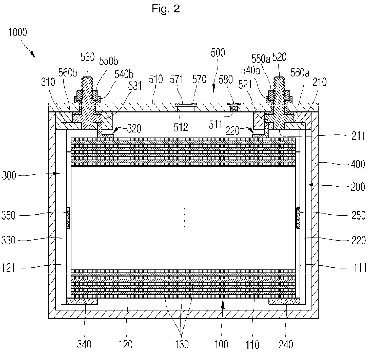
- FIG. 2 is a cross-sectional view of the secondary battery of FIG. 1 , taken along line X-X;
- FIG. 3 is a perspective view of a current collector according to an embodiment of the present invention.
- FIG. 4 is a partial cross-sectional view of the secondary battery of FIG. 1 , taken along line Y-Y;
- FIG. 5 is a partial cross-sectional view of a secondary battery according to another embodiment of the present invention.
- a secondary battery 1000 includes at least one electrode assembly 100, a first collector plate 200, a second collector plate 300, a case 400 and a cap assembly 500.
- the electrode assembly 100 includes a first electrode plate 110, a second electrode plate 120 and a separator 130, which are thin film- or layer-shaped.
- the first electrode plate 110 is formed by coating a first electrode active material such as a transition metal oxide on a first electrode current collector formed of a metal foil made of a material such as aluminum, and includes a first electrode uncoated portion 111 that has no first electrode active material coated thereon.
- the first electrode uncoated portion 111 becomes (or provides) a path for current to flow (e.g., a current path) between the first electrode plate 110 and the outside of the first electrode plate 110.
- the first electrode plate 110 may be made of materials other than the materials listed above.
- the second electrode plate 120 is formed by coating a second electrode active material such as graphite or carbon on a second electrode current collector formed of a metal foil made of a material such as nickel or copper, and includes a second electrode uncoated portion 121 that has no second electrode active material coated thereon.
- the second electrode uncoated portion 121 becomes (or provides) a path for current to flow (e.g., a current path) between the second electrode plate 120 and the outside of the second electrode plate 120.
- the second electrode plate 120 may be made of materials other than the materials listed above.
- first electrode plate 110 and the second electrode plate 120 serve as a positive electrode and a negative electrode, respectively.
- the polarities of the first electrode plate 110 and the second electrode plate 120 are reversed, such that the first electrode plate and the second electrode plate serve as the negative electrode and positive electrode, respectively.
- the separator 130 is positioned between the first electrode plate 110 and the second electrode plate 120 to prevent an electrical short circuit (e.g., to provide electrical insulation) therebetween and to allow lithium ions to move.
- the separator 130 may be wider than a portion of the second electrode plate 120 coated with the second electrode active material in order to prevent or reduce the risk of an electrical short between the first electrode plate 110 and the second electrode plate 120.
- the separator 130 may be made of polyethylene, polypropylene or a composite film thereof. In other embodiments of the present invention the separator 130 may be made of materials other than the materials listed above.
- the electrode assembly 100 is formed by sequentially stacking the separator 130, the first electrode plate 110, the separator 130, and the second electrode plate 120 and winding the stacked structure.
- a plurality of first electrode uncoated portions 111 are drawn out (or protrude) to one side of the electrode assembly 100.
- the plurality of first electrode uncoated portions 111 converge toward the center of the electrode assembly 100 along the thickness of the electrode assembly 100.
- One side of the electrode assembly 100 has a convex shape with respect to the inner wall of the case 400.
- the electrode assembly 100 is housed in the case 400 together with an electrolyte (e.g., the case 400 may surround or contain the electrode assembly 100 together with an electrolyte).
- the electrolyte may include an organic solvent such as ethylene carbonate (EC), propylene carbonate (PC), diethyl carbonate (DEC), ethyl methyl carbonate (EMC), or dimethyl carbonate (DMC), and a lithium salt such as LiPF 6 , or LiBF 4 .
- the electrolyte may be a liquid, a solid or a gel.
- the first collector plate 200 includes a first terminal connecting portion 210, a first top surface support portion 220, first connecting portions 230, a first bottom surface support portion 240 and a first side surface support portion 250.
- the first collector plate 200 is made of a conductive material such as aluminum.
- the first collector plate 200 is coupled to the first electrode uncoated portion 111 protruding at one side of the electrode assembly 100 so that the first collector plate 200 is electrically connected to the first electrode plate 110.
- the first collector plate 200 is spaced apart from the case 400 so as not to contact the inner wall of the case 400.
- the first terminal connecting portion 210 has a plate shape and is located between an upper portion of the electrode assembly 100 and a lower portion of the cap assembly 500.
- the first terminal connecting portion 210 includes a first terminal hole 211.
- the first terminal connecting portion 210 has a first terminal hole 211 in a thickness direction (e.g., in a direction perpendicular to the plane of the plate).
- a first electrode terminal 520 which will be described in more detail later, is inserted through the first terminal hole 211 to be connected to the first terminal connecting portion 210.
- the first top surface support portion 220 is located at one end of the first terminal connecting portion 210.
- the first top surface support portion 220 is a stepped portion and includes a first extending surface 221 extending from one end of the first terminal connecting portion 210 toward the electrode assembly 100 (e.g., downwardly in FIG. 2 ), and first supporting surfaces 222 extending from the first extending surface 221 in a direction parallel with the top surface of the electrode assembly 100.
- the first supporting surfaces 222 prevent or restrict the electrode assembly 100 from moving toward the cap assembly 500 (e.g., upwardly in FIG. 2 ) in the case 400.
- a portion of the first supporting surfaces 222, which faces the top surface of the electrode assembly 100, may be shaped to correspond to a shape of the top surface of the electrode assembly 100.
- the first connecting portions 230 extend from opposing sides of the first terminal connecting portion 210 into the case in a direction substantially perpendicular to the cap plate 500. In this embodiment, the first connecting portions 230 are welded to the first electrode uncoated portion 111 of the electrode assembly 100.
- the first bottom surface support portion 240 extends in a direction from a bottom end of the first connecting portions 230 toward the electrode assembly 100 in a direction parallel with the bottom surface of the electrode assembly 100.
- the first bottom surface support portion 240 faces the bottom surface of the electrode assembly 100, thereby preventing or restricting the electrode assembly 100 from moving in the case 400 away from the cap assembly 500 (e.g., downwardly in FIG. 2 ).
- a surface of the first bottom surface support portion 240, which faces the bottom surface of the electrode assembly 100 may be shaped to correspond to a shape of the bottom surface of the electrode assembly 100. In the embodiment illustrated in FIG.
- the first top surface support portion 220 and the first bottom surface support portion 240 are substantially flat to correspond to respective substantially flat top and bottom surfaces of the electrode assembly 100.
- the first top surface support portion 220 and the first bottom surface support portion 240 have rounded shapes to correspond to rounded top and bottom surfaces of the electrode assembly 100.
- the first side surface support portion 250 is located between the first terminal connecting portion 210 and the first bottom surface support portion 240.
- the first side surface support portion 250 protrudes from the first connecting portions 230 toward one side of the electrode assembly 100.
- the first side surface support portion 250 is located between first electrode uncoated portions 111 of neighboring (or adjacent) electrode assemblies 100, and faces sides of the respective neighboring electrode assemblies 100 in parallel with the sides.
- the first side surface support portion 250 is substantially wedge-shaped.
- the first side surface support portion 250 prevents or restricts the electrode assembly 100 from moving laterally in the case 400 (e.g., left and right in FIG. 2 ).
- the first side surface support portion 250 prevents or restricts the electrode assembly 100 from moving in a direction of width of the case 400 by being wedge-shaped.
- the second collector plate 300 includes a second terminal connecting portion 310, a second top surface support portion 320, second connecting portions 330, a second bottom surface support portion 340 and a second side surface support portion 350.
- the second collector plate 300 is made of a conductive material such as copper.
- the second collector plate 300 is coupled to the second electrode uncoated portion 121 protruding to the other end of the electrode assembly 100 so that it is electrically connected to the second electrode plate 120. Because the second collector plate 300 is located and shaped to correspond to the first collector plate 200 and serves substantially the same function as the first collector plate 200, repeated descriptions thereof will not be given.
- the case 400 has the shape of a rectangular box (or prism) and has a top opening.
- the peripheral portion of the cap assembly 500 substantially corresponds to the top opening of the case 400.
- the electrode assembly 100, the first collector plate 200 and the second collector plate 300 are received (or inserted into the case 400) through the top opening of the case 400.
- the case 400 may be made of a conductive metal such as aluminum, an aluminum alloy or nickel plated steel.
- the interior surface of the case 400 may be insulated, so that the case 400 is electrically insulated from the electrode assembly 100, the first collector plate 200, the second collector plate 300 and the cap assembly 500.
- the case 400 is electrically connected to a cap plate 510, which will later be described, to then serve as an electrode having a polarity.
- the cap assembly 500 includes a cap plate 510, a first electrode terminal 520, a second electrode terminal 530, gaskets 540a and 540b, and nuts 550a and 550b.
- the cap assembly 500 may further include lower insulation members 560a and 560b, a vent plate 570 sealing a vent hole 512 and a plug 580 sealing an electrolyte injection hole 511.
- the cap plate 510 includes an electrolyte injection hole 511 and a vent hole 512.
- the cap plate 510 is sized and shaped to fit the top opening of the case 400.
- the peripheral portion of the cap plate 510 is welded to the top opening of the case 400 to seal the top opening of the case 400.
- the cap plate 510 may made of the same material as the case 400 to facilitate welding between the cap plate 510 and the case 400.
- the electrolyte injection hole 511 passes through one side of the cap plate 510 in a thickness direction (e.g., a direction parallel to the plane of the cap plate). After the top opening of the case 400 is sealed by the cap plate 510 and therefore the electrolyte injection hole 511 is a path for injecting an electrolyte into the case 400.
- the vent hole 512 is located approximately in the center of the cap plate 510 and penetrates through the cap plate 510 in the thickness direction.
- a vent plate 570 which will later be described, is located in the vent hole 512.
- the first electrode terminal 520 penetrates one side of the cap plate 510 and is electrically connected to the first collector plate 200.
- the first electrode terminal 520 may have a pillar shape.
- a thread is located on an outer circumferential surface of an upper portion of the first electrode terminal 520 upwardly exposed from the cap plate 510, and a flange 521 is located on a lower portion of the first electrode terminal 520 below the cap plate 510 to prevent or restrict the first electrode terminal 520 from being dislodged from the cap plate 510.
- the second electrode terminal 530 penetrates the other side of the cap plate 510 (e.g., a side of the cap plate 510 opposite the side penetrated by the first electrode terminal 520) and is electrically connected to the second collector plate 300.
- the second electrode terminal 530 may have a pillar shape.
- a thread is located on an outer circumferential surface of an upper portion of the second electrode terminal 530 upwardly exposed from the cap plate 510, and a flange 531 is located on a lower portion of the second electrode terminal 530 below the cap plate 510 to prevent or restrict the second electrode terminal 530 from being dislodged from the cap plate 510.
- the electrode terminals 520 and 530 serve as paths (e.g., current paths) that electrically connect positive and negative electrodes of the electrode assembly 100 to an external device.
- the gaskets 540a and 540b are located between the first electrode terminal 520 and the cap plate 510 and between the second electrode terminal 530 and the cap plate 510 to seal portions between the electrode terminals 520 and 530 and the cap plate 510. Therefore, the gaskets 540a and 540b prevent (or reduce) external moisture from permeating into the secondary battery 1000 or prevent (or reduce) the electrolyte accommodated in the secondary battery 1000 from being effused (or diffused) outside.
- the gaskets 540a and 540b are made of insulating materials. Therefore, the gaskets 540a and 540b insulate the electrode terminals 520 and 530 from the cap plate 510.
- the nuts 550a and 550b are engaged with the threads of the first and second electrode terminals 520 and 530.
- the nuts 550a and 550b serve to fix the first and second electrode terminals 520 and 530 to the cap plate 510, respectively.
- the lower insulation members 560a and 560b are located between the first terminal connecting portion 210 of the first collector plate 200 and the cap plate 510 and between of the second terminal connecting portion 310 the second collector plate 300 and the cap plate 510.
- the lower insulation members 560a and 560b surround the lower pillar of the first electrode terminal 520 and the lower pillar of the second electrode terminal 530, respectively.
- the lower insulation members 560a and 560b electrically insulate the terminal connecting portions 210 and 310 of the collector plates 200 and 300 from the cap plate 510.
- the vent plate 570 is installed in the vent hole 512 of the cap plate 510.
- the vent plate 570 includes a notch 571 designed to open at a pressure (e.g., a preset pressure). When the internal pressure of the secondary battery 1000 exceeds the preset pressure, the notch 571 is fractured and internal gases are released from the secondary battery 1000, thereby improving safety in use of the secondary battery 1000.
- a pressure e.g., a preset pressure
- the plug 580 seals an electrolyte injection hole 511 of the cap plate 510.
- the secondary battery 1000 includes collector plates 200 and 300 respectively having top surface support portions 220 and 320, bottom surface support portions 240 and 340 and side surface support portions 250 and 350, thereby restricting the movement of the electrode assembly 100 within the case 400. Therefore, the secondary battery 1000 according to this embodiment of the present invention prevents or reduces the likelihood of the electrode assembly 100 and the collector plate 200 from being mechanically and electrically disconnected from each other due to external impacts.
- FIG. 5 is a partial cross-sectional view of this secondary battery.
- the secondary battery 1000a according to the embodiment of the present invention illustrated in FIG. 5 is substantially the same as the secondary battery 1000 according to the previous embodiment of the present invention in view of configurations and functions, except for the shapes of opposing side surfaces of the electrode assembly and shapes of side surface support portions of a collector plate.
- the following description of the secondary battery 1000a will focus on the shape of side surfaces of an electrode assembly 100a and a side surface support portion 250a of a collector plate 200a, and descriptions of the other components will not be repeated.
- a plurality of first electrode uncoated portions 111 a are drawn out (or protrude) to one side of the electrode assembly 100a.
- the plurality of first electrode uncoated portions 111 a converge toward the center of the electrode assembly 100a in the thickness direction.
- One side surface of the electrode assembly 100a is substantially planar.
- the side surface support portion 250a of the collector plate 200a is located between first electrode uncoated portions 111 a of two neighboring electrode assemblies 100a and faces one side surface of each of the two neighboring electrode assemblies 100a.
- the surface of the first side surface support portion 250a facing the side surface of the electrode assembly 100a is substantially planar.
- the first side surface support portion 250a prevents or restricts the electrode assemblies 100a from laterally moving inside the case 400.
- the secondary battery 1000a may further increase the energy capacity relative to the volume, compared to the secondary battery 1000 according to the previous embodiment. That is, in the secondary battery 1000a according to this embodiment, because the side surface of the electrode assembly 100a is planar, a larger area may be coated with an electrode active material compared to the electrode assembly 1000 having a convex side surface, such that the energy capacity relative to the total volume of the battery can be further increased.
Landscapes
- Chemical & Material Sciences (AREA)
- Chemical Kinetics & Catalysis (AREA)
- Electrochemistry (AREA)
- General Chemical & Material Sciences (AREA)
- Engineering & Computer Science (AREA)
- Manufacturing & Machinery (AREA)
- Connection Of Batteries Or Terminals (AREA)
Abstract
Description
- The present invention relates to a secondary battery.
- In a secondary battery, an electrode assembly is fixed to and housed within a case by an uncoated portion which is fixed to a current collector. In order to improve reliability, a secondary battery generally includes a current collector which is constructed to tightly fix the electrode assembly to restrict its movement even when subjected to external impacts.
- Embodiments of the present invention are directed to a secondary battery including a current collector having a structure for fixing an electrode assembly to provide protection for the electrode assembly against damage.
- According to one embodiment of the present invention, a secondary battery includes an electrode assembly, a collector plate electrically connected to the electrode assembly and having a bottom surface support portion facing a bottom surface of the electrode assembly, and a case surrounding the electrode assembly and the collector plate.
- A surface of the bottom surface support portion facing a bottom surface of the electrode assembly may be shaped to correspond to the bottom surface of the electrode assembly.
- The collector plate may include a side surface support portion facing one side surface of the electrode assembly.
- The bottom surface support portion may extend in parallel with the bottom surface of the electrode assembly from a lower end of the side surface support portion to the electrode assembly.
- The electrode assembly may include a plurality of electrode assemblies, and the side surface support portion may be located between a plurality of electrode uncoated portions of neighboring electrode assemblies of the electrode assemblies to face the side surfaces of respective ones of the neighboring electrode assemblies.
- The side surfaces of the electrode assemblies may be planar.
- The secondary battery may further include a cap assembly including a cap plate sealing a top opening of the case, and an electrode terminal penetrating the cap plate.
- The collector plate may include a terminal connecting portion located between an upper portion of the electrode assembly and a lower portion of the cap assembly, and a top surface support portion located at one side of the terminal connecting portion.
- The top surface support portion may include an extending surface extending from one end of the terminal connecting portion toward the upper portion of the electrode assembly, and supporting surfaces extending from the extending surface in a direction substantially parallel with the top surface of the electrode assembly.
- A surface of the supporting surfaces that faces the top surface of the electrode assembly may be shaped to correspond to the top surface of the electrode assembly.
- The collector plate may further include a plurality of connecting portions extending between the top surface support portion and the bottom surface support portion from opposing sides of the terminal connecting portion.
- The connecting portions may be welded to a plurality of electrode uncoated portions of the electrode assembly.
- The collector plate may be spaced apart from an inner wall of the case.
- As described above, the secondary battery according to one embodiment of the present invention can prevent an electrode assembly from moving or restrict the movement of an electrode assembly inside a case.
- In addition, the secondary battery according to one embodiment of the present invention can increase the energy density of the secondary battery.
- Additional aspects and/or advantages of the invention will be set forth in part in the description which follows and, in part, will be obvious from the description, or may be learned by practice of the invention.
- At least some of the above and other features of the invention are set out in the claims.
- The objects, features and advantages of the present invention will be more apparent from the following detailed description in conjunction with the accompanying drawings, in which:
-
FIG. 1 is a perspective view of a secondary battery according to an embodiment of the present invention; -
FIG. 2 is a cross-sectional view of the secondary battery ofFIG. 1 , taken along line X-X; -
FIG. 3 is a perspective view of a current collector according to an embodiment of the present invention; -
FIG. 4 is a partial cross-sectional view of the secondary battery ofFIG. 1 , taken along line Y-Y; and -
FIG. 5 is a partial cross-sectional view of a secondary battery according to another embodiment of the present invention. - Hereinafter, embodiments of the present invention will be described with reference to the accompanying drawings.
- Referring to
FIGS. 1 ,2 ,3 and4 , asecondary battery 1000 according to an embodiment of the present invention includes at least oneelectrode assembly 100, afirst collector plate 200, asecond collector plate 300, acase 400 and acap assembly 500. - The
electrode assembly 100 includes afirst electrode plate 110, asecond electrode plate 120 and aseparator 130, which are thin film- or layer-shaped. - In this embodiment, the
first electrode plate 110 is formed by coating a first electrode active material such as a transition metal oxide on a first electrode current collector formed of a metal foil made of a material such as aluminum, and includes a first electrode uncoatedportion 111 that has no first electrode active material coated thereon. The first electrodeuncoated portion 111 becomes (or provides) a path for current to flow (e.g., a current path) between thefirst electrode plate 110 and the outside of thefirst electrode plate 110. In other embodiments of the present invention, thefirst electrode plate 110 may be made of materials other than the materials listed above. - The
second electrode plate 120 is formed by coating a second electrode active material such as graphite or carbon on a second electrode current collector formed of a metal foil made of a material such as nickel or copper, and includes a second electrode uncoatedportion 121 that has no second electrode active material coated thereon. The second electrodeuncoated portion 121 becomes (or provides) a path for current to flow (e.g., a current path) between thesecond electrode plate 120 and the outside of thesecond electrode plate 120. In other embodiments of the present invention, thesecond electrode plate 120 may be made of materials other than the materials listed above. - In this embodiment, the
first electrode plate 110 and thesecond electrode plate 120 serve as a positive electrode and a negative electrode, respectively. In another embodiment, the polarities of thefirst electrode plate 110 and thesecond electrode plate 120 are reversed, such that the first electrode plate and the second electrode plate serve as the negative electrode and positive electrode, respectively. - The
separator 130 is positioned between thefirst electrode plate 110 and thesecond electrode plate 120 to prevent an electrical short circuit (e.g., to provide electrical insulation) therebetween and to allow lithium ions to move. Theseparator 130 may be wider than a portion of thesecond electrode plate 120 coated with the second electrode active material in order to prevent or reduce the risk of an electrical short between thefirst electrode plate 110 and thesecond electrode plate 120. In addition, theseparator 130 may be made of polyethylene, polypropylene or a composite film thereof. In other embodiments of the present invention theseparator 130 may be made of materials other than the materials listed above. - The
electrode assembly 100 is formed by sequentially stacking theseparator 130, thefirst electrode plate 110, theseparator 130, and thesecond electrode plate 120 and winding the stacked structure. A plurality of first electrode uncoatedportions 111 are drawn out (or protrude) to one side of theelectrode assembly 100. The plurality of first electrode uncoatedportions 111 converge toward the center of theelectrode assembly 100 along the thickness of theelectrode assembly 100. One side of theelectrode assembly 100 has a convex shape with respect to the inner wall of thecase 400. - The
electrode assembly 100 is housed in thecase 400 together with an electrolyte (e.g., thecase 400 may surround or contain theelectrode assembly 100 together with an electrolyte). The electrolyte may include an organic solvent such as ethylene carbonate (EC), propylene carbonate (PC), diethyl carbonate (DEC), ethyl methyl carbonate (EMC), or dimethyl carbonate (DMC), and a lithium salt such as LiPF6, or LiBF4. In addition, the electrolyte may be a liquid, a solid or a gel. - Referring to
FIG. 3 , thefirst collector plate 200 includes a firstterminal connecting portion 210, a first topsurface support portion 220, first connectingportions 230, a first bottomsurface support portion 240 and a first sidesurface support portion 250. Thefirst collector plate 200 is made of a conductive material such as aluminum. In addition, thefirst collector plate 200 is coupled to the first electrode uncoatedportion 111 protruding at one side of theelectrode assembly 100 so that thefirst collector plate 200 is electrically connected to thefirst electrode plate 110. In addition, thefirst collector plate 200 is spaced apart from thecase 400 so as not to contact the inner wall of thecase 400. - The first
terminal connecting portion 210 has a plate shape and is located between an upper portion of theelectrode assembly 100 and a lower portion of thecap assembly 500. In addition, the firstterminal connecting portion 210 includes afirst terminal hole 211. The firstterminal connecting portion 210 has afirst terminal hole 211 in a thickness direction (e.g., in a direction perpendicular to the plane of the plate). In addition, afirst electrode terminal 520, which will be described in more detail later, is inserted through thefirst terminal hole 211 to be connected to the first terminal connectingportion 210. - The first top
surface support portion 220 is located at one end of the firstterminal connecting portion 210. In this embodiment, the first topsurface support portion 220 is a stepped portion and includes a first extendingsurface 221 extending from one end of the firstterminal connecting portion 210 toward the electrode assembly 100 (e.g., downwardly inFIG. 2 ), and first supportingsurfaces 222 extending from the first extendingsurface 221 in a direction parallel with the top surface of theelectrode assembly 100. The first supportingsurfaces 222 prevent or restrict theelectrode assembly 100 from moving toward the cap assembly 500 (e.g., upwardly inFIG. 2 ) in thecase 400. - Further, a portion of the first supporting
surfaces 222, which faces the top surface of theelectrode assembly 100, may be shaped to correspond to a shape of the top surface of theelectrode assembly 100. - The first connecting
portions 230 extend from opposing sides of the firstterminal connecting portion 210 into the case in a direction substantially perpendicular to thecap plate 500. In this embodiment, the first connectingportions 230 are welded to the first electrodeuncoated portion 111 of theelectrode assembly 100. - The first bottom
surface support portion 240 extends in a direction from a bottom end of the first connectingportions 230 toward theelectrode assembly 100 in a direction parallel with the bottom surface of theelectrode assembly 100. The first bottomsurface support portion 240 faces the bottom surface of theelectrode assembly 100, thereby preventing or restricting theelectrode assembly 100 from moving in thecase 400 away from the cap assembly 500 (e.g., downwardly inFIG. 2 ). In addition, a surface of the first bottomsurface support portion 240, which faces the bottom surface of theelectrode assembly 100, may be shaped to correspond to a shape of the bottom surface of theelectrode assembly 100. In the embodiment illustrated inFIG. 2 , the first topsurface support portion 220 and the first bottomsurface support portion 240 are substantially flat to correspond to respective substantially flat top and bottom surfaces of theelectrode assembly 100. In other embodiments, the first topsurface support portion 220 and the first bottomsurface support portion 240 have rounded shapes to correspond to rounded top and bottom surfaces of theelectrode assembly 100. - The first side
surface support portion 250 is located between the firstterminal connecting portion 210 and the first bottomsurface support portion 240. The first sidesurface support portion 250 protrudes from the first connectingportions 230 toward one side of theelectrode assembly 100. In addition, the first sidesurface support portion 250 is located between first electrodeuncoated portions 111 of neighboring (or adjacent)electrode assemblies 100, and faces sides of the respectiveneighboring electrode assemblies 100 in parallel with the sides. Thus, referring toFIG.3 and4 , the first sidesurface support portion 250 is substantially wedge-shaped. The first sidesurface support portion 250 prevents or restricts theelectrode assembly 100 from moving laterally in the case 400 (e.g., left and right inFIG. 2 ). In addition, the first sidesurface support portion 250 prevents or restricts theelectrode assembly 100 from moving in a direction of width of thecase 400 by being wedge-shaped. - The
second collector plate 300 includes a secondterminal connecting portion 310, a second topsurface support portion 320, second connectingportions 330, a second bottomsurface support portion 340 and a second sidesurface support portion 350. Thesecond collector plate 300 is made of a conductive material such as copper. In addition, thesecond collector plate 300 is coupled to the second electrodeuncoated portion 121 protruding to the other end of theelectrode assembly 100 so that it is electrically connected to thesecond electrode plate 120. Because thesecond collector plate 300 is located and shaped to correspond to thefirst collector plate 200 and serves substantially the same function as thefirst collector plate 200, repeated descriptions thereof will not be given. - The
case 400 has the shape of a rectangular box (or prism) and has a top opening. The peripheral portion of thecap assembly 500 substantially corresponds to the top opening of thecase 400. Theelectrode assembly 100, thefirst collector plate 200 and thesecond collector plate 300 are received (or inserted into the case 400) through the top opening of thecase 400. - The
case 400 may be made of a conductive metal such as aluminum, an aluminum alloy or nickel plated steel. In addition, the interior surface of thecase 400 may be insulated, so that thecase 400 is electrically insulated from theelectrode assembly 100, thefirst collector plate 200, thesecond collector plate 300 and thecap assembly 500. In some embodiments, thecase 400 is electrically connected to acap plate 510, which will later be described, to then serve as an electrode having a polarity. - The
cap assembly 500 includes acap plate 510, afirst electrode terminal 520, asecond electrode terminal 530,gaskets cap assembly 500 may further includelower insulation members vent plate 570 sealing avent hole 512 and aplug 580 sealing anelectrolyte injection hole 511. - The
cap plate 510 includes anelectrolyte injection hole 511 and avent hole 512. Thecap plate 510 is sized and shaped to fit the top opening of thecase 400. In addition, the peripheral portion of thecap plate 510 is welded to the top opening of thecase 400 to seal the top opening of thecase 400. Thecap plate 510 may made of the same material as thecase 400 to facilitate welding between thecap plate 510 and thecase 400. - The
electrolyte injection hole 511 passes through one side of thecap plate 510 in a thickness direction (e.g., a direction parallel to the plane of the cap plate). After the top opening of thecase 400 is sealed by thecap plate 510 and therefore theelectrolyte injection hole 511 is a path for injecting an electrolyte into thecase 400. - The
vent hole 512 is located approximately in the center of thecap plate 510 and penetrates through thecap plate 510 in the thickness direction. In addition, avent plate 570, which will later be described, is located in thevent hole 512. - The
first electrode terminal 520 penetrates one side of thecap plate 510 and is electrically connected to thefirst collector plate 200. Thefirst electrode terminal 520 may have a pillar shape. A thread is located on an outer circumferential surface of an upper portion of thefirst electrode terminal 520 upwardly exposed from thecap plate 510, and aflange 521 is located on a lower portion of thefirst electrode terminal 520 below thecap plate 510 to prevent or restrict thefirst electrode terminal 520 from being dislodged from thecap plate 510. - The
second electrode terminal 530 penetrates the other side of the cap plate 510 (e.g., a side of thecap plate 510 opposite the side penetrated by the first electrode terminal 520) and is electrically connected to thesecond collector plate 300. Thesecond electrode terminal 530 may have a pillar shape. A thread is located on an outer circumferential surface of an upper portion of thesecond electrode terminal 530 upwardly exposed from thecap plate 510, and aflange 531 is located on a lower portion of thesecond electrode terminal 530 below thecap plate 510 to prevent or restrict thesecond electrode terminal 530 from being dislodged from thecap plate 510. - The
electrode terminals electrode assembly 100 to an external device. - The
gaskets first electrode terminal 520 and thecap plate 510 and between thesecond electrode terminal 530 and thecap plate 510 to seal portions between theelectrode terminals cap plate 510. Therefore, thegaskets secondary battery 1000 or prevent (or reduce) the electrolyte accommodated in thesecondary battery 1000 from being effused (or diffused) outside. Thegaskets gaskets electrode terminals cap plate 510. - The
nuts second electrode terminals second electrode terminals cap plate 510, respectively. - The
lower insulation members terminal connecting portion 210 of thefirst collector plate 200 and thecap plate 510 and between of the secondterminal connecting portion 310 thesecond collector plate 300 and thecap plate 510. In addition, thelower insulation members first electrode terminal 520 and the lower pillar of thesecond electrode terminal 530, respectively. Thus, thelower insulation members terminal connecting portions collector plates cap plate 510. - The
vent plate 570 is installed in thevent hole 512 of thecap plate 510. In addition, thevent plate 570 includes anotch 571 designed to open at a pressure (e.g., a preset pressure). When the internal pressure of thesecondary battery 1000 exceeds the preset pressure, thenotch 571 is fractured and internal gases are released from thesecondary battery 1000, thereby improving safety in use of thesecondary battery 1000. - Once the top opening of the 400 is sealed by the
cap plate 510, theplug 580 seals anelectrolyte injection hole 511 of thecap plate 510. - As described above, the
secondary battery 1000 according to one embodiment of the present invention includescollector plates surface support portions surface support portions surface support portions electrode assembly 100 within thecase 400. Therefore, thesecondary battery 1000 according to this embodiment of the present invention prevents or reduces the likelihood of theelectrode assembly 100 and thecollector plate 200 from being mechanically and electrically disconnected from each other due to external impacts. - Next, a secondary battery according to another embodiment of the present invention will be described with reference to
FIG. 5. FIG. 5 is a partial cross-sectional view of this secondary battery. - The
secondary battery 1000a according to the embodiment of the present invention illustrated inFIG. 5 is substantially the same as thesecondary battery 1000 according to the previous embodiment of the present invention in view of configurations and functions, except for the shapes of opposing side surfaces of the electrode assembly and shapes of side surface support portions of a collector plate. Thus, the following description of thesecondary battery 1000a will focus on the shape of side surfaces of anelectrode assembly 100a and a sidesurface support portion 250a of acollector plate 200a, and descriptions of the other components will not be repeated. - Referring to
FIG. 5 , a plurality of first electrodeuncoated portions 111 a are drawn out (or protrude) to one side of theelectrode assembly 100a. The plurality of first electrodeuncoated portions 111 a converge toward the center of theelectrode assembly 100a in the thickness direction. One side surface of theelectrode assembly 100a is substantially planar. - Meanwhile, the side
surface support portion 250a of thecollector plate 200a is located between first electrodeuncoated portions 111 a of two neighboringelectrode assemblies 100a and faces one side surface of each of the two neighboringelectrode assemblies 100a. Thus, referring toFIG.5 , the surface of the first sidesurface support portion 250a facing the side surface of theelectrode assembly 100a is substantially planar. The first sidesurface support portion 250a prevents or restricts theelectrode assemblies 100a from laterally moving inside thecase 400. - In addition to the above-stated effect of preventing or restricting the
electrode assemblies 1000a from moving inside thecase 400, thesecondary battery 1000a may further increase the energy capacity relative to the volume, compared to thesecondary battery 1000 according to the previous embodiment. That is, in thesecondary battery 1000a according to this embodiment, because the side surface of theelectrode assembly 100a is planar, a larger area may be coated with an electrode active material compared to theelectrode assembly 1000 having a convex side surface, such that the energy capacity relative to the total volume of the battery can be further increased. - Although certain embodiments of the present invention have been described, those skilled in the art will understand that various modifications and variations can be made without departing from the scope of the present invention as disclosed in the accompanying claims and equivalents thereof.
Claims (13)
- A secondary battery comprising:an electrode assembly;a collector plate electrically connected to the electrode assembly and having a bottom surface support portion facing a bottom surface of the electrode assembly; anda case surrounding the electrode assembly and the collector plate.
- A secondary battery according to claim 1, wherein a surface of the bottom surface support portion facing a bottom surface of the electrode assembly is shaped to correspond to the bottom surface of the electrode assembly.
- A secondary battery according to claim 1 or 2, wherein the collector plate includes a side surface support portion facing one side surface of the electrode assembly.
- A secondary battery according to claim 3, wherein the bottom surface support portion extends from a lower end of the side surface support portion to the electrode assembly in a direction that is parallel with the bottom surface of the electrode assembly.
- A secondary battery of claim 3 or 4, wherein at least a part of the side surface support portion is located between a plurality of electrode uncoated portions of the electrode assembly.
- A secondary battery according to claim 5, wherein a side surface of the electrode assembly is planar.
- A secondary battery according to any preceding claim, further comprising a cap assembly including a cap plate sealing a top opening of the case and an electrode terminal penetrating the cap plate.
- A secondary battery according to claim 7, wherein the collector plate comprises:a terminal connecting portion located between an upper portion of the electrode assembly and a lower portion of the cap assembly; anda top surface support portion located at one side of the terminal connecting portion.
- A secondary battery according to claim 8, wherein the top surface support portion comprises:an extending surface extending from one end of the terminal connecting portion toward the upper portion of the electrode assembly; andsupporting surfaces extending from the extending surface in a direction substantially parallel with the top surface of the electrode assembly.
- A secondary battery according to claim 9, wherein a surface of the supporting surfaces that faces the top surface of the electrode assembly is shaped to correspond to the top surface of the electrode assembly.
- A secondary battery according to claim 8, 9 or 10, wherein the collector plate further comprises a plurality of connecting portions extending between the top surface support portion and the bottom surface support portion from opposing sides of the terminal connecting portion.
- A secondary battery according to claim 11, wherein the connecting portions are welded to a plurality of electrode uncoated portions of the electrode assembly.
- A secondary battery according to any preceding claim, wherein the collector plate is spaced apart from an inner wall of the case.
Applications Claiming Priority (1)
| Application Number | Priority Date | Filing Date | Title |
|---|---|---|---|
| KR1020110007785A KR101285940B1 (en) | 2011-01-26 | 2011-01-26 | Secondary battery |
Publications (2)
| Publication Number | Publication Date |
|---|---|
| EP2482366A1 true EP2482366A1 (en) | 2012-08-01 |
| EP2482366B1 EP2482366B1 (en) | 2016-09-21 |
Family
ID=44514542
Family Applications (1)
| Application Number | Title | Priority Date | Filing Date |
|---|---|---|---|
| EP11176035.1A Active EP2482366B1 (en) | 2011-01-26 | 2011-07-29 | Secondary Battery |
Country Status (3)
| Country | Link |
|---|---|
| US (1) | US8741475B2 (en) |
| EP (1) | EP2482366B1 (en) |
| KR (1) | KR101285940B1 (en) |
Cited By (2)
| Publication number | Priority date | Publication date | Assignee | Title |
|---|---|---|---|---|
| CN106165152A (en) * | 2014-04-18 | 2016-11-23 | 日立汽车系统株式会社 | Square secondary battery |
| CN108199072A (en) * | 2018-01-16 | 2018-06-22 | 宁德时代新能源科技股份有限公司 | Rechargeable battery |
Families Citing this family (5)
| Publication number | Priority date | Publication date | Assignee | Title |
|---|---|---|---|---|
| JP6360305B2 (en) * | 2013-12-27 | 2018-07-18 | 日立オートモティブシステムズ株式会社 | Prismatic secondary battery |
| JP6947575B2 (en) * | 2017-07-31 | 2021-10-13 | 株式会社Gsユアサ | Manufacturing method of power storage element |
| JP7024288B2 (en) * | 2017-09-27 | 2022-02-24 | 株式会社Gsユアサ | Power storage element |
| CN117096514B (en) * | 2023-10-20 | 2024-03-29 | 江苏时代新能源科技有限公司 | Top cap subassembly, battery and consumer |
| CN119812604B (en) * | 2024-10-08 | 2026-04-03 | 比亚迪股份有限公司 | Cover plate assembly, individual battery cells, battery modules, battery packs and electrical equipment |
Citations (2)
| Publication number | Priority date | Publication date | Assignee | Title |
|---|---|---|---|---|
| JP2006228551A (en) * | 2005-02-17 | 2006-08-31 | Toyota Motor Corp | Current collecting terminal and power storage device including the terminal |
| EP2244328A2 (en) * | 2009-04-21 | 2010-10-27 | SB LiMotive Co., Ltd. | Rechargeable battery having a current collecting plate |
Family Cites Families (11)
| Publication number | Priority date | Publication date | Assignee | Title |
|---|---|---|---|---|
| JP3831595B2 (en) | 2000-09-26 | 2006-10-11 | 三洋電機株式会社 | Cylindrical secondary battery |
| JP2004303500A (en) | 2003-03-31 | 2004-10-28 | Sanyo Electric Co Ltd | Prismatic battery |
| JP4532448B2 (en) | 2005-10-26 | 2010-08-25 | パナソニックEvエナジー株式会社 | Rectangular battery electrode unit, rectangular battery, and method of manufacturing rectangular battery electrode unit |
| JP5023559B2 (en) | 2006-06-02 | 2012-09-12 | トヨタ自動車株式会社 | Battery manufacturing method |
| CN101517785B (en) * | 2006-09-20 | 2011-09-21 | 松下电器产业株式会社 | Secondary battery and method for manufacturing secondary battery |
| JP2008185850A (en) | 2007-01-30 | 2008-08-14 | Kyocera Mita Corp | Image forming apparatus |
| CN101960649A (en) | 2008-03-07 | 2011-01-26 | 松下电器产业株式会社 | Lithium ion secondary battery and manufacturing method thereof |
| JP2010135170A (en) * | 2008-12-04 | 2010-06-17 | Hitachi Vehicle Energy Ltd | Lithium secondary battery, secondary battery module, and secondary battery pack |
| US8822065B2 (en) * | 2009-03-11 | 2014-09-02 | Samsung Sdi Co., Ltd. | Rechargeable battery with current collector plate |
| JP5633031B2 (en) | 2009-03-26 | 2014-12-03 | エリーパワー株式会社 | Secondary battery and method for manufacturing secondary battery |
| US8999543B2 (en) * | 2009-09-21 | 2015-04-07 | Samsung Sdi Co., Ltd. | Rechargeable battery with larger curved ends having different radius of curvature |
-
2011
- 2011-01-26 KR KR1020110007785A patent/KR101285940B1/en active Active
- 2011-07-29 EP EP11176035.1A patent/EP2482366B1/en active Active
- 2011-09-13 US US13/231,896 patent/US8741475B2/en active Active
Patent Citations (2)
| Publication number | Priority date | Publication date | Assignee | Title |
|---|---|---|---|---|
| JP2006228551A (en) * | 2005-02-17 | 2006-08-31 | Toyota Motor Corp | Current collecting terminal and power storage device including the terminal |
| EP2244328A2 (en) * | 2009-04-21 | 2010-10-27 | SB LiMotive Co., Ltd. | Rechargeable battery having a current collecting plate |
Cited By (5)
| Publication number | Priority date | Publication date | Assignee | Title |
|---|---|---|---|---|
| CN106165152A (en) * | 2014-04-18 | 2016-11-23 | 日立汽车系统株式会社 | Square secondary battery |
| EP3133673A4 (en) * | 2014-04-18 | 2018-01-03 | Hitachi Automotive Systems, Ltd. | Rectangular secondary battery |
| CN106165152B (en) * | 2014-04-18 | 2019-07-12 | 日立汽车系统株式会社 | Square secondary battery |
| CN108199072A (en) * | 2018-01-16 | 2018-06-22 | 宁德时代新能源科技股份有限公司 | Rechargeable battery |
| US11929521B2 (en) | 2018-01-16 | 2024-03-12 | Contemporary Amperex Technology Co., Limited | Rechargeable battery |
Also Published As
| Publication number | Publication date |
|---|---|
| EP2482366B1 (en) | 2016-09-21 |
| KR20120086510A (en) | 2012-08-03 |
| US8741475B2 (en) | 2014-06-03 |
| KR101285940B1 (en) | 2013-07-12 |
| US20120189907A1 (en) | 2012-07-26 |
Similar Documents
| Publication | Publication Date | Title |
|---|---|---|
| US10826048B2 (en) | Secondary battery | |
| US8771854B2 (en) | Secondary battery | |
| KR101233573B1 (en) | Secondary battery | |
| US8841022B2 (en) | Terminal of secondary battery and method of assembling the same | |
| US9263723B2 (en) | Secondary battery having a collecting plate | |
| US8728644B2 (en) | Rechargeable battery | |
| US9136524B2 (en) | Secondary battery | |
| US10367186B2 (en) | Secondary battery including an insulating member | |
| US8932752B2 (en) | Battery having a bent case and battery pack including the same | |
| KR101093932B1 (en) | Secondary battery | |
| US9190636B2 (en) | Rechargeable battery | |
| EP2482366B1 (en) | Secondary Battery | |
| US8785037B2 (en) | Secondary battery with stepped cap plate | |
| EP2477250B1 (en) | Rechargeable battery | |
| US20230343992A1 (en) | Secondary battery | |
| KR20260002386A (en) | Secondary Battery | |
| KR20210038029A (en) | Secondary battery | |
| KR20240057717A (en) | Secondary battery | |
| US9577229B2 (en) | Secondary battery | |
| US9028999B2 (en) | Secondary battery | |
| KR20170081446A (en) | Secondary battery | |
| US20260121219A1 (en) | Secondary battery |
Legal Events
| Date | Code | Title | Description |
|---|---|---|---|
| PUAI | Public reference made under article 153(3) epc to a published international application that has entered the european phase |
Free format text: ORIGINAL CODE: 0009012 |
|
| 17P | Request for examination filed |
Effective date: 20120329 |
|
| AK | Designated contracting states |
Kind code of ref document: A1 Designated state(s): AL AT BE BG CH CY CZ DE DK EE ES FI FR GB GR HR HU IE IS IT LI LT LU LV MC MK MT NL NO PL PT RO RS SE SI SK SM TR |
|
| AX | Request for extension of the european patent |
Extension state: BA ME |
|
| RAP1 | Party data changed (applicant data changed or rights of an application transferred) |
Owner name: SAMSUNG SDI CO., LTD. Owner name: ROBERT BOSCH GMBH |
|
| 17Q | First examination report despatched |
Effective date: 20140514 |
|
| GRAP | Despatch of communication of intention to grant a patent |
Free format text: ORIGINAL CODE: EPIDOSNIGR1 |
|
| RIC1 | Information provided on ipc code assigned before grant |
Ipc: H01M 2/26 20060101AFI20160302BHEP Ipc: H01M 2/02 20060101ALN20160302BHEP Ipc: H01M 10/04 20060101ALI20160302BHEP Ipc: H01M 2/04 20060101ALI20160302BHEP |
|
| INTG | Intention to grant announced |
Effective date: 20160323 |
|
| RIN1 | Information on inventor provided before grant (corrected) |
Inventor name: MOON, JONGSEOK Inventor name: KIM, DUKJUNG |
|
| GRAS | Grant fee paid |
Free format text: ORIGINAL CODE: EPIDOSNIGR3 |
|
| GRAA | (expected) grant |
Free format text: ORIGINAL CODE: 0009210 |
|
| AK | Designated contracting states |
Kind code of ref document: B1 Designated state(s): AL AT BE BG CH CY CZ DE DK EE ES FI FR GB GR HR HU IE IS IT LI LT LU LV MC MK MT NL NO PL PT RO RS SE SI SK SM TR |
|
| REG | Reference to a national code |
Ref country code: GB Ref legal event code: FG4D |
|
| REG | Reference to a national code |
Ref country code: CH Ref legal event code: EP |
|
| REG | Reference to a national code |
Ref country code: AT Ref legal event code: REF Ref document number: 831677 Country of ref document: AT Kind code of ref document: T Effective date: 20161015 |
|
| REG | Reference to a national code |
Ref country code: IE Ref legal event code: FG4D |
|
| REG | Reference to a national code |
Ref country code: DE Ref legal event code: R096 Ref document number: 602011030510 Country of ref document: DE |
|
| REG | Reference to a national code |
Ref country code: LT Ref legal event code: MG4D Ref country code: NL Ref legal event code: MP Effective date: 20160921 |
|
| PG25 | Lapsed in a contracting state [announced via postgrant information from national office to epo] |
Ref country code: LT Free format text: LAPSE BECAUSE OF FAILURE TO SUBMIT A TRANSLATION OF THE DESCRIPTION OR TO PAY THE FEE WITHIN THE PRESCRIBED TIME-LIMIT Effective date: 20160921 Ref country code: NO Free format text: LAPSE BECAUSE OF FAILURE TO SUBMIT A TRANSLATION OF THE DESCRIPTION OR TO PAY THE FEE WITHIN THE PRESCRIBED TIME-LIMIT Effective date: 20161221 Ref country code: FI Free format text: LAPSE BECAUSE OF FAILURE TO SUBMIT A TRANSLATION OF THE DESCRIPTION OR TO PAY THE FEE WITHIN THE PRESCRIBED TIME-LIMIT Effective date: 20160921 Ref country code: RS Free format text: LAPSE BECAUSE OF FAILURE TO SUBMIT A TRANSLATION OF THE DESCRIPTION OR TO PAY THE FEE WITHIN THE PRESCRIBED TIME-LIMIT Effective date: 20160921 |
|
| REG | Reference to a national code |
Ref country code: AT Ref legal event code: MK05 Ref document number: 831677 Country of ref document: AT Kind code of ref document: T Effective date: 20160921 |
|
| PG25 | Lapsed in a contracting state [announced via postgrant information from national office to epo] |
Ref country code: LV Free format text: LAPSE BECAUSE OF FAILURE TO SUBMIT A TRANSLATION OF THE DESCRIPTION OR TO PAY THE FEE WITHIN THE PRESCRIBED TIME-LIMIT Effective date: 20160921 Ref country code: GR Free format text: LAPSE BECAUSE OF FAILURE TO SUBMIT A TRANSLATION OF THE DESCRIPTION OR TO PAY THE FEE WITHIN THE PRESCRIBED TIME-LIMIT Effective date: 20161222 Ref country code: SE Free format text: LAPSE BECAUSE OF FAILURE TO SUBMIT A TRANSLATION OF THE DESCRIPTION OR TO PAY THE FEE WITHIN THE PRESCRIBED TIME-LIMIT Effective date: 20160921 Ref country code: NL Free format text: LAPSE BECAUSE OF FAILURE TO SUBMIT A TRANSLATION OF THE DESCRIPTION OR TO PAY THE FEE WITHIN THE PRESCRIBED TIME-LIMIT Effective date: 20160921 |
|
| PG25 | Lapsed in a contracting state [announced via postgrant information from national office to epo] |
Ref country code: RO Free format text: LAPSE BECAUSE OF FAILURE TO SUBMIT A TRANSLATION OF THE DESCRIPTION OR TO PAY THE FEE WITHIN THE PRESCRIBED TIME-LIMIT Effective date: 20160921 Ref country code: EE Free format text: LAPSE BECAUSE OF FAILURE TO SUBMIT A TRANSLATION OF THE DESCRIPTION OR TO PAY THE FEE WITHIN THE PRESCRIBED TIME-LIMIT Effective date: 20160921 |
|
| PG25 | Lapsed in a contracting state [announced via postgrant information from national office to epo] |
Ref country code: CZ Free format text: LAPSE BECAUSE OF FAILURE TO SUBMIT A TRANSLATION OF THE DESCRIPTION OR TO PAY THE FEE WITHIN THE PRESCRIBED TIME-LIMIT Effective date: 20160921 Ref country code: BG Free format text: LAPSE BECAUSE OF FAILURE TO SUBMIT A TRANSLATION OF THE DESCRIPTION OR TO PAY THE FEE WITHIN THE PRESCRIBED TIME-LIMIT Effective date: 20161221 Ref country code: ES Free format text: LAPSE BECAUSE OF FAILURE TO SUBMIT A TRANSLATION OF THE DESCRIPTION OR TO PAY THE FEE WITHIN THE PRESCRIBED TIME-LIMIT Effective date: 20160921 Ref country code: PT Free format text: LAPSE BECAUSE OF FAILURE TO SUBMIT A TRANSLATION OF THE DESCRIPTION OR TO PAY THE FEE WITHIN THE PRESCRIBED TIME-LIMIT Effective date: 20170123 Ref country code: IS Free format text: LAPSE BECAUSE OF FAILURE TO SUBMIT A TRANSLATION OF THE DESCRIPTION OR TO PAY THE FEE WITHIN THE PRESCRIBED TIME-LIMIT Effective date: 20170121 Ref country code: SK Free format text: LAPSE BECAUSE OF FAILURE TO SUBMIT A TRANSLATION OF THE DESCRIPTION OR TO PAY THE FEE WITHIN THE PRESCRIBED TIME-LIMIT Effective date: 20160921 Ref country code: BE Free format text: LAPSE BECAUSE OF FAILURE TO SUBMIT A TRANSLATION OF THE DESCRIPTION OR TO PAY THE FEE WITHIN THE PRESCRIBED TIME-LIMIT Effective date: 20160921 Ref country code: AT Free format text: LAPSE BECAUSE OF FAILURE TO SUBMIT A TRANSLATION OF THE DESCRIPTION OR TO PAY THE FEE WITHIN THE PRESCRIBED TIME-LIMIT Effective date: 20160921 Ref country code: SM Free format text: LAPSE BECAUSE OF FAILURE TO SUBMIT A TRANSLATION OF THE DESCRIPTION OR TO PAY THE FEE WITHIN THE PRESCRIBED TIME-LIMIT Effective date: 20160921 Ref country code: PL Free format text: LAPSE BECAUSE OF FAILURE TO SUBMIT A TRANSLATION OF THE DESCRIPTION OR TO PAY THE FEE WITHIN THE PRESCRIBED TIME-LIMIT Effective date: 20160921 |
|
| REG | Reference to a national code |
Ref country code: DE Ref legal event code: R097 Ref document number: 602011030510 Country of ref document: DE |
|
| REG | Reference to a national code |
Ref country code: FR Ref legal event code: PLFP Year of fee payment: 7 |
|
| PG25 | Lapsed in a contracting state [announced via postgrant information from national office to epo] |
Ref country code: IT Free format text: LAPSE BECAUSE OF FAILURE TO SUBMIT A TRANSLATION OF THE DESCRIPTION OR TO PAY THE FEE WITHIN THE PRESCRIBED TIME-LIMIT Effective date: 20160921 |
|
| PLBE | No opposition filed within time limit |
Free format text: ORIGINAL CODE: 0009261 |
|
| STAA | Information on the status of an ep patent application or granted ep patent |
Free format text: STATUS: NO OPPOSITION FILED WITHIN TIME LIMIT |
|
| PG25 | Lapsed in a contracting state [announced via postgrant information from national office to epo] |
Ref country code: DK Free format text: LAPSE BECAUSE OF FAILURE TO SUBMIT A TRANSLATION OF THE DESCRIPTION OR TO PAY THE FEE WITHIN THE PRESCRIBED TIME-LIMIT Effective date: 20160921 |
|
| 26N | No opposition filed |
Effective date: 20170622 |
|
| PG25 | Lapsed in a contracting state [announced via postgrant information from national office to epo] |
Ref country code: SI Free format text: LAPSE BECAUSE OF FAILURE TO SUBMIT A TRANSLATION OF THE DESCRIPTION OR TO PAY THE FEE WITHIN THE PRESCRIBED TIME-LIMIT Effective date: 20160921 |
|
| REG | Reference to a national code |
Ref country code: CH Ref legal event code: PL |
|
| PG25 | Lapsed in a contracting state [announced via postgrant information from national office to epo] |
Ref country code: LI Free format text: LAPSE BECAUSE OF NON-PAYMENT OF DUE FEES Effective date: 20170731 Ref country code: CH Free format text: LAPSE BECAUSE OF NON-PAYMENT OF DUE FEES Effective date: 20170731 |
|
| REG | Reference to a national code |
Ref country code: IE Ref legal event code: MM4A |
|
| PG25 | Lapsed in a contracting state [announced via postgrant information from national office to epo] |
Ref country code: LU Free format text: LAPSE BECAUSE OF NON-PAYMENT OF DUE FEES Effective date: 20170729 |
|
| REG | Reference to a national code |
Ref country code: FR Ref legal event code: PLFP Year of fee payment: 8 |
|
| PG25 | Lapsed in a contracting state [announced via postgrant information from national office to epo] |
Ref country code: IE Free format text: LAPSE BECAUSE OF NON-PAYMENT OF DUE FEES Effective date: 20170729 |
|
| PG25 | Lapsed in a contracting state [announced via postgrant information from national office to epo] |
Ref country code: MT Free format text: LAPSE BECAUSE OF NON-PAYMENT OF DUE FEES Effective date: 20170729 |
|
| PG25 | Lapsed in a contracting state [announced via postgrant information from national office to epo] |
Ref country code: AL Free format text: LAPSE BECAUSE OF FAILURE TO SUBMIT A TRANSLATION OF THE DESCRIPTION OR TO PAY THE FEE WITHIN THE PRESCRIBED TIME-LIMIT Effective date: 20160921 |
|
| PG25 | Lapsed in a contracting state [announced via postgrant information from national office to epo] |
Ref country code: MC Free format text: LAPSE BECAUSE OF FAILURE TO SUBMIT A TRANSLATION OF THE DESCRIPTION OR TO PAY THE FEE WITHIN THE PRESCRIBED TIME-LIMIT Effective date: 20160921 Ref country code: HU Free format text: LAPSE BECAUSE OF FAILURE TO SUBMIT A TRANSLATION OF THE DESCRIPTION OR TO PAY THE FEE WITHIN THE PRESCRIBED TIME-LIMIT; INVALID AB INITIO Effective date: 20110729 |
|
| PG25 | Lapsed in a contracting state [announced via postgrant information from national office to epo] |
Ref country code: CY Free format text: LAPSE BECAUSE OF NON-PAYMENT OF DUE FEES Effective date: 20160921 |
|
| PG25 | Lapsed in a contracting state [announced via postgrant information from national office to epo] |
Ref country code: MK Free format text: LAPSE BECAUSE OF FAILURE TO SUBMIT A TRANSLATION OF THE DESCRIPTION OR TO PAY THE FEE WITHIN THE PRESCRIBED TIME-LIMIT Effective date: 20160921 |
|
| PG25 | Lapsed in a contracting state [announced via postgrant information from national office to epo] |
Ref country code: TR Free format text: LAPSE BECAUSE OF FAILURE TO SUBMIT A TRANSLATION OF THE DESCRIPTION OR TO PAY THE FEE WITHIN THE PRESCRIBED TIME-LIMIT Effective date: 20160921 |
|
| PG25 | Lapsed in a contracting state [announced via postgrant information from national office to epo] |
Ref country code: HR Free format text: LAPSE BECAUSE OF FAILURE TO SUBMIT A TRANSLATION OF THE DESCRIPTION OR TO PAY THE FEE WITHIN THE PRESCRIBED TIME-LIMIT Effective date: 20160921 |
|
| REG | Reference to a national code |
Ref country code: DE Ref legal event code: R079 Ref document number: 602011030510 Country of ref document: DE Free format text: PREVIOUS MAIN CLASS: H01M0002260000 Ipc: H01M0050531000 |
|
| P01 | Opt-out of the competence of the unified patent court (upc) registered |
Effective date: 20230530 |
|
| PGFP | Annual fee paid to national office [announced via postgrant information from national office to epo] |
Ref country code: GB Payment date: 20250626 Year of fee payment: 15 |
|
| PGFP | Annual fee paid to national office [announced via postgrant information from national office to epo] |
Ref country code: FR Payment date: 20250623 Year of fee payment: 15 |
|
| PGFP | Annual fee paid to national office [announced via postgrant information from national office to epo] |
Ref country code: DE Payment date: 20250624 Year of fee payment: 15 |