EP2482363A1 - Secondary battery - Google Patents
Secondary battery Download PDFInfo
- Publication number
- EP2482363A1 EP2482363A1 EP20110167154 EP11167154A EP2482363A1 EP 2482363 A1 EP2482363 A1 EP 2482363A1 EP 20110167154 EP20110167154 EP 20110167154 EP 11167154 A EP11167154 A EP 11167154A EP 2482363 A1 EP2482363 A1 EP 2482363A1
- Authority
- EP
- European Patent Office
- Prior art keywords
- cap plate
- electrode assembly
- recessed portion
- rechargeable battery
- electrode
- Prior art date
- Legal status (The legal status is an assumption and is not a legal conclusion. Google has not performed a legal analysis and makes no representation as to the accuracy of the status listed.)
- Granted
Links
Images




Classifications
-
- H—ELECTRICITY
- H01—ELECTRIC ELEMENTS
- H01M—PROCESSES OR MEANS, e.g. BATTERIES, FOR THE DIRECT CONVERSION OF CHEMICAL ENERGY INTO ELECTRICAL ENERGY
- H01M50/00—Constructional details or processes of manufacture of the non-active parts of electrochemical cells other than fuel cells, e.g. hybrid cells
- H01M50/10—Primary casings; Jackets or wrappings
- H01M50/147—Lids or covers
- H01M50/148—Lids or covers characterised by their shape
- H01M50/15—Lids or covers characterised by their shape for prismatic or rectangular cells
-
- H—ELECTRICITY
- H01—ELECTRIC ELEMENTS
- H01M—PROCESSES OR MEANS, e.g. BATTERIES, FOR THE DIRECT CONVERSION OF CHEMICAL ENERGY INTO ELECTRICAL ENERGY
- H01M10/00—Secondary cells; Manufacture thereof
- H01M10/05—Accumulators with non-aqueous electrolyte
- H01M10/052—Li-accumulators
- H01M10/0525—Rocking-chair batteries, i.e. batteries with lithium insertion or intercalation in both electrodes; Lithium-ion batteries
-
- H—ELECTRICITY
- H01—ELECTRIC ELEMENTS
- H01M—PROCESSES OR MEANS, e.g. BATTERIES, FOR THE DIRECT CONVERSION OF CHEMICAL ENERGY INTO ELECTRICAL ENERGY
- H01M50/00—Constructional details or processes of manufacture of the non-active parts of electrochemical cells other than fuel cells, e.g. hybrid cells
- H01M50/10—Primary casings; Jackets or wrappings
- H01M50/102—Primary casings; Jackets or wrappings characterised by their shape or physical structure
- H01M50/103—Primary casings; Jackets or wrappings characterised by their shape or physical structure prismatic or rectangular
-
- H—ELECTRICITY
- H01—ELECTRIC ELEMENTS
- H01M—PROCESSES OR MEANS, e.g. BATTERIES, FOR THE DIRECT CONVERSION OF CHEMICAL ENERGY INTO ELECTRICAL ENERGY
- H01M50/00—Constructional details or processes of manufacture of the non-active parts of electrochemical cells other than fuel cells, e.g. hybrid cells
- H01M50/10—Primary casings; Jackets or wrappings
- H01M50/116—Primary casings; Jackets or wrappings characterised by the material
- H01M50/117—Inorganic material
- H01M50/119—Metals
-
- H—ELECTRICITY
- H01—ELECTRIC ELEMENTS
- H01M—PROCESSES OR MEANS, e.g. BATTERIES, FOR THE DIRECT CONVERSION OF CHEMICAL ENERGY INTO ELECTRICAL ENERGY
- H01M50/00—Constructional details or processes of manufacture of the non-active parts of electrochemical cells other than fuel cells, e.g. hybrid cells
- H01M50/10—Primary casings; Jackets or wrappings
- H01M50/147—Lids or covers
- H01M50/155—Lids or covers characterised by the material
- H01M50/157—Inorganic material
- H01M50/159—Metals
-
- H—ELECTRICITY
- H01—ELECTRIC ELEMENTS
- H01M—PROCESSES OR MEANS, e.g. BATTERIES, FOR THE DIRECT CONVERSION OF CHEMICAL ENERGY INTO ELECTRICAL ENERGY
- H01M50/00—Constructional details or processes of manufacture of the non-active parts of electrochemical cells other than fuel cells, e.g. hybrid cells
- H01M50/10—Primary casings; Jackets or wrappings
- H01M50/147—Lids or covers
- H01M50/166—Lids or covers characterised by the methods of assembling casings with lids
- H01M50/169—Lids or covers characterised by the methods of assembling casings with lids by welding, brazing or soldering
-
- H—ELECTRICITY
- H01—ELECTRIC ELEMENTS
- H01M—PROCESSES OR MEANS, e.g. BATTERIES, FOR THE DIRECT CONVERSION OF CHEMICAL ENERGY INTO ELECTRICAL ENERGY
- H01M50/00—Constructional details or processes of manufacture of the non-active parts of electrochemical cells other than fuel cells, e.g. hybrid cells
- H01M50/10—Primary casings; Jackets or wrappings
- H01M50/172—Arrangements of electric connectors penetrating the casing
- H01M50/174—Arrangements of electric connectors penetrating the casing adapted for the shape of the cells
- H01M50/176—Arrangements of electric connectors penetrating the casing adapted for the shape of the cells for prismatic or rectangular cells
-
- H—ELECTRICITY
- H01—ELECTRIC ELEMENTS
- H01M—PROCESSES OR MEANS, e.g. BATTERIES, FOR THE DIRECT CONVERSION OF CHEMICAL ENERGY INTO ELECTRICAL ENERGY
- H01M50/00—Constructional details or processes of manufacture of the non-active parts of electrochemical cells other than fuel cells, e.g. hybrid cells
- H01M50/30—Arrangements for facilitating escape of gases
-
- H—ELECTRICITY
- H01—ELECTRIC ELEMENTS
- H01M—PROCESSES OR MEANS, e.g. BATTERIES, FOR THE DIRECT CONVERSION OF CHEMICAL ENERGY INTO ELECTRICAL ENERGY
- H01M50/00—Constructional details or processes of manufacture of the non-active parts of electrochemical cells other than fuel cells, e.g. hybrid cells
- H01M50/50—Current conducting connections for cells or batteries
- H01M50/543—Terminals
- H01M50/547—Terminals characterised by the disposition of the terminals on the cells
- H01M50/55—Terminals characterised by the disposition of the terminals on the cells on the same side of the cell
-
- H—ELECTRICITY
- H01—ELECTRIC ELEMENTS
- H01M—PROCESSES OR MEANS, e.g. BATTERIES, FOR THE DIRECT CONVERSION OF CHEMICAL ENERGY INTO ELECTRICAL ENERGY
- H01M50/00—Constructional details or processes of manufacture of the non-active parts of electrochemical cells other than fuel cells, e.g. hybrid cells
- H01M50/50—Current conducting connections for cells or batteries
- H01M50/543—Terminals
- H01M50/552—Terminals characterised by their shape
- H01M50/553—Terminals adapted for prismatic, pouch or rectangular cells
-
- H—ELECTRICITY
- H01—ELECTRIC ELEMENTS
- H01M—PROCESSES OR MEANS, e.g. BATTERIES, FOR THE DIRECT CONVERSION OF CHEMICAL ENERGY INTO ELECTRICAL ENERGY
- H01M50/00—Constructional details or processes of manufacture of the non-active parts of electrochemical cells other than fuel cells, e.g. hybrid cells
- H01M50/50—Current conducting connections for cells or batteries
- H01M50/543—Terminals
- H01M50/562—Terminals characterised by the material
-
- H—ELECTRICITY
- H01—ELECTRIC ELEMENTS
- H01M—PROCESSES OR MEANS, e.g. BATTERIES, FOR THE DIRECT CONVERSION OF CHEMICAL ENERGY INTO ELECTRICAL ENERGY
- H01M50/00—Constructional details or processes of manufacture of the non-active parts of electrochemical cells other than fuel cells, e.g. hybrid cells
- H01M50/50—Current conducting connections for cells or batteries
- H01M50/572—Means for preventing undesired use or discharge
- H01M50/574—Devices or arrangements for the interruption of current
- H01M50/579—Devices or arrangements for the interruption of current in response to shock
-
- Y—GENERAL TAGGING OF NEW TECHNOLOGICAL DEVELOPMENTS; GENERAL TAGGING OF CROSS-SECTIONAL TECHNOLOGIES SPANNING OVER SEVERAL SECTIONS OF THE IPC; TECHNICAL SUBJECTS COVERED BY FORMER USPC CROSS-REFERENCE ART COLLECTIONS [XRACs] AND DIGESTS
- Y02—TECHNOLOGIES OR APPLICATIONS FOR MITIGATION OR ADAPTATION AGAINST CLIMATE CHANGE
- Y02E—REDUCTION OF GREENHOUSE GAS [GHG] EMISSIONS, RELATED TO ENERGY GENERATION, TRANSMISSION OR DISTRIBUTION
- Y02E60/00—Enabling technologies; Technologies with a potential or indirect contribution to GHG emissions mitigation
- Y02E60/10—Energy storage using batteries
-
- Y—GENERAL TAGGING OF NEW TECHNOLOGICAL DEVELOPMENTS; GENERAL TAGGING OF CROSS-SECTIONAL TECHNOLOGIES SPANNING OVER SEVERAL SECTIONS OF THE IPC; TECHNICAL SUBJECTS COVERED BY FORMER USPC CROSS-REFERENCE ART COLLECTIONS [XRACs] AND DIGESTS
- Y02—TECHNOLOGIES OR APPLICATIONS FOR MITIGATION OR ADAPTATION AGAINST CLIMATE CHANGE
- Y02P—CLIMATE CHANGE MITIGATION TECHNOLOGIES IN THE PRODUCTION OR PROCESSING OF GOODS
- Y02P70/00—Climate change mitigation technologies in the production process for final industrial or consumer products
- Y02P70/50—Manufacturing or production processes characterised by the final manufactured product
Definitions
- Embodiments relate to a secondary battery.
- Secondary batteries are rechargeable unlike primary batteries.
- a low capacity battery including a battery cell in the form of a pack may be used for small portable electronic devices such as cellular phones and camcorders, and a high capacity battery including dozens of battery cells connected to one another may be used as a motor-driving power source for electric scooters, hybrid vehicles, or electric vehicles.
- Secondary batteries are manufactured in various shapes such as a cylindrical shape and a pouch shape.
- a secondary battery includes an electrode assembly formed by disposing an insulating separator between a positive electrode plate and a negative electrode plate, a case in which the electrode assembly is accommodated together with electrolyte, and a cap plate used to close the case.
- the electrode assembly is connected to terminals penetrating the cap plate and protruding outward.
- a rechargeable battery including an electrode assembly, a case accommodating the electrode assembly, a cap plate sealing an opening in the case, and electrode terminals extending through the cap plate at opposite ends of the cap plate, the cap plate including a recessed portion extending in one direction between the electrode terminals.
- the recessed portion may extend from a top surface of the cap plate toward the electrode assembly.
- the cap plate may have a planar area, more than half of the planar area being occupied by the recessed portion.
- the recessed portion may include a bottom portion and connection portions connecting the recessed portion to the top surface of the cap plate.
- the recessed portion may include at least one rounded portion between the bottom portion and the connection portions.
- the recessed portion includes a plurality of rounded portions between the bottom portion and the connection portions.
- the electrode assembly may include a convex outer portion that faces the cap plate.
- the bottom portion of the recessed portion of the cap plate may be planar.
- the bottom portion of the recessed portion of the cap plate may have a convex shape corresponding in shape to the convex outer portion of the electrode assembly.
- the bottom portion of the recessed portion of the cap plate may include a safety vent.
- the rechargeable battery may further include an impact damper between the recessed portion of the cap plate and the electrode assembly, wherein the impact damper is attached to a surface of the recessed portion of the cap plate facing the electrode assembly.
- the impact damper may include an elastomer.
- the impact damper may include perfluoroalkoxy (PFA), polypropylene (PP), or polyethylene (PE).
- PFA perfluoroalkoxy
- PP polypropylene
- PE polyethylene
- the electrode assembly may include two or more electrode assembly units, each electrode assembly unit including a convex upper portion facing the cap plate.
- the bottom portion of the recessed portion of the cap plate may be planar.
- the bottom portion of the recessed portion of the cap plate may include two or more convex portions, each convex portion corresponding in shape to one of the convex outer portions of the electrode assembly units.
- the bottom portion of the recessed portion of the cap plate may include a rounded protrusion extending downwardly from each convex portion and towards a cleft between the convex upper portions of the electrode assembly units.
- a rechargeable battery including a case having a pair of oppositely disposed wide sides, oppositely disposed narrow sides, a top side, and a bottom side opposite to the top side, the wide sides extending longitudinally in a first lateral direction between the narrow sides, an electrode assembly in the case, a cap plate at the top side of the case, the cap plate including a first part disposed in a plane of the top side of the case and a second part spaced from the first part toward the electrode assembly in a second direction perpendicular to the first direction, the second part being elongated and extending longitudinally in the first lateral direction.
- the rechargeable battery may further include a first terminal that includes a first collecting plate that contacts an end of the electrode assembly and a first collecting terminal that extends downwardly from the first part of the cap plate to contact the first collecting plate, the first collecting terminal being disposed entirely above the electrode assembly, the bottom portion of the second part of the cap plate being spaced from the first part of the cap plate by a greater distance than a distance that the first collecting terminal extends downwardly from the first part of the cap plate.
- the rechargeable battery may further include a second terminal spaced in the first lateral direction from the first terminal, the second part being between the first terminal and the second terminal.
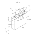
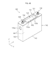
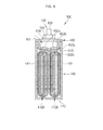
- FIGS. 1A and 1B illustrate perspective view relating to a secondary battery according to an embodiment
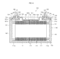
- FIG. 1C is a sectional view taken along line 1C-1C of FIG. 1A ;
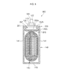
- FIG. 2 illustrates a sectional view taken along line 2-2 of FIG. 1A ;
- FIG. 3 illustrates a sectional view relating to a secondary battery according to another embodiment
- FIG. 4 illustrates a sectional view relating to a secondary battery according to another embodiment
- FIG. 5 illustrates a sectional view relating to a secondary battery according to another embodiment
- FIG. 6 illustrates a sectional view relating to a secondary battery according to another embodiment
- FIG. 7 illustrates a sectional view relating to a secondary battery according to another embodiment
- FIG. 8 illustrates a sectional view relating to a secondary battery according to another embodiment
- FIG. 9 illustrates a sectional view relating to a secondary battery according to another embodiment.
- FIG. 10 illustrates a sectional view relating to a secondary battery according to another embodiment.
- FIGS. 1A and 1B are perspective views illustrating a secondary battery 101 (102) according to an embodiment, and FIG. 1C is a sectional view taken along line 1C-1C of FIG. 1A .
- the secondary battery 101 (102) of the current embodiment includes an electrode assembly 110, a first terminal 120, a second terminal 130, a case 140, and a cap plate 150.
- the electrode assembly 110 includes a first electrode plate 111, a separator 113, and a second electrode plate 112, which may have a thin plate or film shape.
- the electrode assembly 110 may be formed by winding the above-listed parts in a jelly-roll type or by stacking the parts.
- the first electrode plate 111 may function as a negative electrode
- the second electrode plate 112 may function as a positive electrode.
- the first electrode plate 111 and the second electrode plate 112 may function oppositely.
- the first electrode plate 111 may be formed by applying a first electrode active material such as graphite or carbon to a first electrode collector formed of metal foil such as nickel or copper foil.
- the first electrode plate 111 may include a first electrode non-coating portion 111a to which the first electrode active metal is not applied.
- the first electrode non-coating portion 111a may function as a current flow passage between the first electrode plate 111 and the first terminal 120.
- materials that can be used to form the first electrode plate 111 are not limited to the above-mentioned materials.
- the second electrode plate 112 may be formed by applying a second electrode active material such as a transition metal oxide to a second electrode collector formed of metal foil such as aluminum foil.
- the second electrode plate 112 may include a second electrode non-coating portion 112a to which the second electrode active metal is not applied.
- the second electrode non-coating portion 112a may function as a current flow passage between the second electrode plate 112 and the second terminal 130.
- materials that can be used to form the second electrode plate 112 are not limited to the above-mentioned materials.
- the polarities of the first and second electrode plates 111 and 112 may be reversed.
- the separator 113 may be disposed between the first electrode plate 111 and the second electrode plate 112 to prevent a short circuit between the first and second electrode plates 111 and 112. Lithium ions can move through the separator 113.
- the separator 113 may be formed of a polyethylene film, a polypropylene film, or a film including polyethylene and polypropylene. In the current embodiment, materials that can be used to form the separator 113 are not limited to the above-mentioned materials.
- the first and second terminals 120 and 130 may be disposed at respective sides of the electrode assembly 110 and may be electrically connected to the first and second electrode plates 111 and 112, respectively.
- the electrode assembly 110 may be accommodated in the case 140 together with electrolyte.
- the electrolyte may include an organic solvent such as ethylene carbonate (EC), propylene carbonate (PC), diethyl carbonate (DEC), ethyl methyl carbonate (EMC), or dimethyl carbonate (DMC); and a lithium salt such as LiPF 6 or LiBF 4 .
- the electrolyte may be liquid, solid, or gel.
- the first terminal 120 may be formed of a metal, or an equivalent thereof, and is electrically connected to the first electrode plate 111.
- the first terminal 120 may include a first collecting plate 121, a first collecting terminal 122, and a first coupling terminal 123.
- the first terminal 120 may further include a seal gasket 124 disposed between the first collecting terminal 122 and the cap plate 150.
- the seal gasket 124 electrically insulates the first collecting terminal 122 and the cap plate 150 from each other and prevents leakage of the electrolyte and permeation of moisture.
- the first terminal 120 may further include a lower insulator 125 disposed between the first collecting terminal 122 and the cap plate 150 for electric insulation therebetween.
- the first terminal 120 may further include an upper insulator 126 disposed between the first coupling terminal 123 and the cap plate 150 for electrical insulation therebetween.
- the first collecting plate 121 contacts the first electrode non-coating portion 111a, which protrudes from an end of the electrode assembly 110.
- the first collecting plate 121 may be welded to the first electrode non-coating portion 111a.
- the first collecting plate 121 may have an approximately reverse L-shape, and a terminal hole 121d may be formed in the upper portion of the first collecting plate 121.
- a lower part of the first collecting terminal 122 may be fitted and coupled to the terminal hole 121d.
- the first collecting plate 121 may be formed of copper or a copper alloy.
- the material of the first collecting plate 121 is not limited thereto.
- the first collecting terminal 122 penetrates the cap plate 150 (described below) and may protrude upwardly by a predetermined length.
- the first collecting terminal 122 may be electrically connected to the first collecting plate 121 at the lower side of the cap plate 150.
- the first collecting terminal 122 may extend and protrude upward from the cap plate 150 by a predetermined length.
- the first collecting terminal 122 may include a flange 122a at a position under the cap plate 150 so that the first collecting terminal 122 cannot be separated from the cap plate 150.
- a part of the first collecting terminal 122 lower than the flange 122a may be inserted in the terminal hole 121d of the first collecting plate 121 and may be coupled thereto by riveting or welding.
- a plurality of threads may be formed on a part of the first collecting terminal 122 higher than the flange 122a for coupling with the first coupling terminal 123.
- the upper part of the first collecting terminal 122 may be coupled to the first coupling terminal 123 (described below) by a bolt-nut coupling method.
- the first collecting terminal 122 may be formed of one of copper, copper alloy, and an equivalent thereof.
- the material of the first collecting terminal 122 is not limited thereto.
- the first coupling terminal 123 may have a hexagonal nut shape, and a threaded penetration hole 123d may be formed through the center of the first coupling terminal 123 so that the first collecting terminal 122 can be inserted and coupled with the first coupling terminal 123.
- the first coupling terminal 123 may be formed of one of stainless steel, copper, copper alloy, aluminum, aluminum alloy, and an equivalent thereof. However, the current embodiment is not limited to such materials.
- the second terminal 130 may be formed of a metal or an equivalent thereof, and is electrically connected to the second electrode non-coating portion 112a of the second electrode plate 112.
- the second terminal 130 may include a second collecting plate 131, a second collecting terminal 132, and a second coupling terminal 133.
- the second terminal 130 may have the same shape and structure as that of the first terminal 120. Thus, the shape and structure of the second terminal 130 will not described again.
- the second collecting plate 131 and the second collecting terminal 132 may be formed of one of aluminum, an aluminum alloy, and an equivalent thereof. However, the current embodiment is not limited to such materials.
- the second coupling terminal 133 may be formed of one of stainless steel, aluminum, aluminum alloy, copper, copper alloy, and an equivalent thereof. However, the current embodiment is not limited thereto.
- the second coupling terminal 133 may be electrically connected to the cap plate 150.
- the case 140 and the cap plate 150 may have the same polarity (for example, positive polarity) as that of the second terminal 130.
- reference numerals 134, 135, and 136 denote a seal gasket, a lower insulator, and an upper insulator, respectively.
- reference numeral 131d denotes a penetration hole formed through the second collecting plate 131
- reference numeral 132a denotes a flange formed on the second collecting terminal 132
- reference numeral 133d denotes a threaded penetration hole formed through the second coupling terminal 133.
- the first terminal 120 and the second terminal 130 may have other structures instead of the above-described structures. That is, the current embodiment is not limited thereto the above-described structures of the first and second terminals 120 and 130.
- the case 140 may be formed of a conductive metal such as aluminum, aluminum alloy, or steel plated with nickel, and may have an approximately hexahedron shape with an opening, so that the electrode assembly 110, the first terminal 120, and the second terminal 130 can be inserted and placed in the case 140.
- the case 140 may include relatively wide sides 141 facing each other, relatively narrow sides 142 facing each other and connected to the wide sides 141, and a bottom side 143 connecting the wide sides 141 and the narrow sides 142. A side opposite to the bottom side 143 is open.
- FIG. 1C illustrates a state where the case 140 and the cap plate 150 are coupled to each other, and the opened side of the case 140 is not shown. However, the peripheral part of the cap plate 150 substantially corresponds to the opened side of the case 140.
- the inner surface of the case 140 may be treated to be electrically insulated from the electrode assembly 110, the first and second terminals 120 and 130, and the cap plate 150.
- the cap plate 150 is coupled to the case 140.
- the cap plate 150 may be coupled to the case 140 by welding.
- the cap plate 150 may include an upper portion 151 that is welded to upper ends of the wide sides 141 and the narrow sides 142, and a recessed portion 152 that bends to extend from the upper portion 151 toward the electrode assembly 110 by a predetermined depth.
- the upper portion 151 may include a planar top surface.
- the cap plate 150 may have a rectangular plate shape with a central recess portion 152.
- the case 140 may include a pair of oppositely disposed wide sides 141, oppositely disposed narrow sides 142, a top side, and a bottom side 143 opposite to the top side, the wide sides 141 extending longitudinally in a first lateral direction between the narrow sides 142.
- the cap plate 150 may be at the top side of the case 140 and may include a first part 151 disposed in a plane of the top side of the case 140 and a second part 152 spaced from the first part 151 toward the electrode assembly 110 in a second direction perpendicular to the first direction, the second part 152 being elongated and extending longitudinally in the first lateral direction.
- the recessed portion or second part 152 includes a bottom portion 152a lower than the upper portion 151 of the cap plate, and four connection portions 152b connecting the bottom portion 152a and the top surface or first part 151.
- the bottom portion 152a may be convex in an outward direction.
- the bottom portion 152a may have a shape corresponding to the outer shape of the electrode assembly 110.
- the electrode assembly 110 may be approximately convex upward along the length direction of the cap plate 150, and accordingly, the bottom portion 152a may be approximately convex along the length direction of the cap plate 150.
- the recessed portion 152 may be formed by placing the cap plate 150 on a jig (not shown) having a recess, and then pressing or stamping the cap plate 150 with a tool (not shown) having a protrusion.
- the method of forming the recessed portion 152 is not limited thereto.
- the recessed portion 152 is lower than the upper portion 151 and is slightly lower than lower parts of the first and second terminals 120 and 130. That is, the bottom portion 152a of the recessed portion 152 may be slightly lower than the first collecting terminal 122 and the lower insulator 125 corresponding to the first collecting terminal 122, and the second collecting terminal 132 and the lower insulator 135 corresponding to the second collecting terminal 132. Therefore, if the secondary battery 101 (102) is dropped and impacted, the electrode assembly 110 may be brought into contact with the bottom portion 152a of the recessed portion 152 before contacting the first and second collecting terminals 122 and 132 and the lower insulators 125 and 135. Therefore, the electrode assembly 110 may be protected because impacts may be absorbed and dampened by the bottom portion 152a with a contact area that is wider than that of the first and second collecting terminals 122 and 132 and the lower insulators 125 and 135.
- An electrolyte injection hole 153 may be formed through the upper portion 151, and a plug 154 may be coupled to the electrolyte injection hole 153.
- a safety vent 155 having a relatively thin thickness may be formed on the recessed portion 152 so that gas can be discharged through the safety vent 155 if the inside pressure of the case 140 increases above a predetermined level.
- the safety vent 155 may be formed on the narrow side 142 of the case 140 as in the secondary battery 102 shown in FIG. 1B .
- the safety vent 155 may be formed on the wide side 141 or bottom side 143 of the case 140.
- the electrolyte injection hole 153 and the plug 154 may be provided at the wide side 141, narrow side 142, or bottom side 143 of the case 140 instead of at the cap plate 150.
- the cap plate 150 and the case 140 may be formed of the same material.
- the cap plate 150 may be formed of a conductive metal material such as aluminum, aluminum alloy, and steel plated with nickel. However, the material of the cap plate 150 is not limited thereto.
- the volume of a void inside the case 140 can be reduced by forming the recessed portion 152 on the cap plate 150 in a manner such that the recessed portion 152 is convex toward the electrode assembly 110. Therefore, although gas is abnormally generated in the secondary battery 101 (102), the secondary battery 101 (102) can be safely and reliably used because the safety vent 155 rapidly responds to the abnormal generation of gas.
- the recessed portion 152 has a shape corresponding to the outer shape of the electrode assembly 110, the recessed portion 152 can absorb impacts for the electrode assembly 110 when the secondary battery 101 (102) is dropped and impacted. That is, although the secondary battery 101 (102) is dropped and impacted, since the electrode assembly 110 is brought into contact with the relatively wide recessed portion 152 instead of the relatively sharp terminals 120 and 130 or lower insulators 125 and 135, the electrode assembly 110 can be less damaged.
- FIG. 2 is a sectional view taken along line 2-2 of FIG. 1A .
- the cap plate 150 includes the upper portion 151 and the recessed portion 152.
- the recessed portion 152 is lower than the upper portion 151.
- the recessed portion 152 includes the bottom portion 152a, which bends convexly outward, and the connection portions 152b connecting the bottom portion 152a and the upper portion 151. Even the highest region of the bottom portion 152a is lower than the upper portion 151.
- the bottom portion 152a may have a shape approximately corresponding to the convex outer portion of the electrode assembly 110, and the connection portions 152b may be approximately parallel with the wide sides 141 of the case 140.
- the upper part of the electrode assembly 110 may be approximately convex in the upward direction, and the bottom portion 152a, spaced apart from the electrode assembly 110, may be approximately convex in the same upward direction.
- Rounded portions 152c may be formed between the bottom portion 152a and the connection portions 152b. Therefore, is the electrode assembly 110 directly collides with the rounded portions 152c when the secondary battery 101 is dropped and impacted, breakage of the electrode assembly 110 may be avoided.
- the bottom portion 152a and the electrode assembly 110 are spaced a predetermined distance from each other. That is, in general, the bottom portion 152a and the electrode assembly 110 do not contact each other but are spaced a predetermined distance from each other. Therefore, a gas passage may be provided so that gas can flow to the safety vent 155 in case of an abnormal situation. If the bottom portion 152a and the electrode assembly 110 were to contact each other in a normal operation state, a gas passage to the safety vent 155 may not be formed, and the electrode assembly 110 may be damaged due to continuous fine vibrations and friction with the recessed portion 152.
- the recessed portion 152 of the cap plate 150 is spaced apart from the electrode assembly 110 to ensure a gas passage to the safety vent 155.
- the volume of a void inside the case 140 can be reduced. Furthermore, if the secondary battery 101 is dropped and impacted, damage to the electrode assembly 110 can be minimized.
- FIG. 3 is a sectional view illustrating a secondary battery 300 according to another embodiment.
- a cap plate 350 includes an upper portion 351 and a recessed portion 352.
- the upper portion 351 may include a planar top surface.
- the recessed portion 352 includes a bottom portion 352a, which is approximately planar, connection portions 352b connecting the bottom portion 352a and the upper portion 351, and rounded portions 352c formed between the bottom portion 352a and the connection portions 352b.
- the bottom portion 352a may be approximately planar regardless of the shape of an upper part of an electrode assembly 110. That is, the bottom portion 352a may be approximately parallel with a bottom side 143 of a case 140.
- the recessed portion 352 having the planar bottom portion 352a may be formed by a one-time pressing or stamping process. That is, the cap plate 350 may be manufactured through a simple manufacturing process as compared with the cap plate 150 of the above-described embodiment.
- the volume of a void inside the case 140 can be reduced owing to the recessed portion 352 of the cap plate 350, and the electrode assembly 110 can be less damaged owning to the planar bottom portion 352a if the secondary battery 300 were to be dropped and impacted.
- the recessed portion 352 can be formed through a simple manufacturing process.
- FIG. 4 is a sectional view illustrating a secondary battery 400 according to another embodiment.
- the secondary battery 400 of the current embodiment includes two electrode assemblies 110A and 110B. It is to be understood that in the current embodiment, the secondary battery 400 may include more than two electrode assemblies.
- a cap plate 450 includes an upper portion 451 and a recessed portion 452.
- the recessed portion 452 includes a pair of bottom portions 452a which bend convexly outward, and connection portions 452b connecting the planar portion 451 and the bottom portions 452a.
- the bottom portions 452a have shapes approximately corresponding to the upper parts of the electrode assemblies 110A and 110B, and the connection portions 452b are approximately parallel with wide sides 141 of a case 140.
- the upper parts of the pair of electrode assemblies 110A and 110B are approximately convex in the upward direction
- the pair of bottom portions 452a are spaced apart from the pair of electrode assemblies 110A and 110B and are approximately convex in the upward direction.
- rounded portions 452c are formed between the bottom portions 452a and the connection portions 452b, and a rounded portion 452d is formed at a center lower end of the bottom portions 452a.
- the rounded portion 452d may extend downwardly towards a cleft between the convex upper portions of the electrode assembly units 110A, 110B.
- the volume of a void inside the case 140 can be reduced, and damage to the electrode assemblies 110A and 110B can be minimized if the secondary battery 400 is dropped and impacted.
- FIG. 5 is a sectional view illustrating a secondary battery 500 according to another embodiment.
- a cap plate 550 includes a upper portion 551 and a recessed portion 552.
- the recessed portion 552 includes a bottom portion 552a which is approximately planar, and connection portions 552b connecting the bottom portion 552a and the upper portion 551.
- the bottom portion 552a is approximately planar regardless of the shapes of upper parts of a pair of electrode assemblies 110A and 110B. That is, the bottom portion 552a is approximately parallel with a bottom side 143 of a case 140.
- Rounded portions 552c are formed between the bottom portion 552a and the connection portions 552b. Therefore, if the electrode assemblies 110A and 110B are brought into contact with the round portions 552c when the secondary battery 500 is dropped and impacted, damage to the electrode assemblies 110A and 110B may be minimized.
- the volume of a void inside the case 140 can be reduced owing to the recessed portion 552 of the cap plate 550, and the electrode assemblies 110A and 110B can be less damaged owing to the planar bottom portion 552a if the secondary battery 500 is dropped and impacted.
- FIG. 6 is a sectional view illustrating a secondary battery 600 according to another embodiment.
- an impact damper 610 may be further disposed between a recessed portion 152 of a cap plate 150 and an electrode assembly 110.
- the impact damper 610 having a predetermined thickness may be coated on or attached to the bottom surface of a bottom portion 152a of the recessed portion 152. If a safety vent 155 is formed on the bottom portion 152a, a hole 610a having a predetermined diameter may be formed in the impact damper 610 at a position corresponding to the safety vent 155.
- the impact damper 610 is spaced apart from the electrode assembly 110 so that a degassing passage can be formed and continuous friction between the impact damper 610 and the electrode assembly 110 can be prevented.
- the impact damper 610 may include an elastomer that has the properties of rubber and does not react with electrolyte.
- the impact damper 610 may be formed of a resin including perfluoroalkoxy (PFA), polypropylene (PP), or polyethylene (PE), which do not react with electrolytes.
- PFA perfluoroalkoxy
- PP polypropylene
- PE polyethylene
- the current embodiment is not limited thereto.
- the volume of a void inside the case 140 can be reduced, and the electrode assembly 110 can be less damaged owing to the impact damper 610 if the secondary battery 600 is dropped and impacted. That is, when the secondary battery 600 is dropped and impacted, the electrode assembly 110 may be brought into contact with the impact damper 610 formed of a soft material instead of being brought into contact with the metallic recessed portion 152.
- FIG. 7 is a sectional view illustrating a secondary battery 600 according to another embodiment.
- an impact damper 610 having a predetermined thickness is formed on the bottom surface of a bottom portion 152a of a recessed portion 152 of a cap plate 150.
- the impact damper 610 is spaced a predetermined distance from an electrode assembly 110.
- the bottom portion 152a may bend convexly upward, and the impact damper 610 formed on the bottom portion 152a may extend to cover rounded portions 152c disposed at both sides of the bottom portion 152a.
- the impact damper 610 may be formed of the same material as described above, and thus a description thereof will not be repeated.
- the volume of a void inside a case 140 can be reduced owing to the recessed portion 152.
- the electrode assembly 110 can be less damaged owing to the impact damper 610 formed on the bottom surfaces of the bottom portion 152a and the round portions 152c of the recessed portion 152.
- FIG. 8 is a sectional view illustrating a secondary battery 800 according to another embodiment.
- a bottom portion 352a of a recessed portion 352 is approximately planar, and an impact damper 810 having a predetermined thickness is formed on the bottom surface of the bottom portion 352a.
- the impact damper 810 may extend to rounded portions 352c disposed at both sides of the bottom portion 352a.
- FIG. 9 is a sectional view illustrating a secondary battery 900 according to another embodiment.
- a recessed portion 452 includes a pair of bottom portions 452a, which are approximately convex in an upward direction, and rounded portions 452b and 452c formed at the center and both sides of the recessed portion 452.
- An impact damper 910 may be formed on the bottom portions 452a and the rounded portions 452b and 452c.
- FIG. 10 is a sectional view illustrating a secondary battery 1000 according to another embodiment.
- a recessed portion 552 includes a bottom portion 552a, which is approximately planar and disposed above a pair of electrode assemblies 110A and 110B, and an impact damper 1010 is formed on the bottom surface of the bottom portion 552a.
- the impact damper 1010 covers rounded portions 552c disposed at both sides of the bottom portion 552a.
- the recessed portion may be formed on the cap plate in a direction toward the electrode assembly. Therefore, the volume of a void of the secondary battery can be reduced. Owing to the reduced void volume of the secondary battery, if gas is abnormally generated in the secondary battery, the safety vent can be rapidly opened so that the secondary battery can be safely and reliably used.
- the recessed portion may be formed on the cap plate in a direction toward the electrode assembly. Therefore, the electrode assembly may be less damaged if the secondary battery is dropped and impacted. That is, if the secondary battery is dropped and impacted, contact between the electrode assembly and sharp regions of the terminals may be avoided. Instead, the electrode assembly may be brought into contact with the relatively wide recessed portion, and thus the impact can be absorbed and reduced. Therefore, the electrode assembly can be less damaged, and the secondary battery can be safely and reliably used for a long time.
- Example embodiments have been disclosed herein, and although specific terms are employed, they are used and are to be interpreted in a generic and descriptive sense only and not for purpose of limitation.
Landscapes
- Chemical & Material Sciences (AREA)
- Chemical Kinetics & Catalysis (AREA)
- Electrochemistry (AREA)
- General Chemical & Material Sciences (AREA)
- Inorganic Chemistry (AREA)
- Engineering & Computer Science (AREA)
- Materials Engineering (AREA)
- Manufacturing & Machinery (AREA)
- Sealing Battery Cases Or Jackets (AREA)
- Connection Of Batteries Or Terminals (AREA)
- Secondary Cells (AREA)
- Gas Exhaust Devices For Batteries (AREA)
Abstract
Description
- The entirety of
U.S. Provisional Application No. 61/437,988, filed on January 31, 2011 U.S. Non-provisional Application No. 13/064,582, filed on April 1, 2011 , and entitled: "Secondary Battery," is incorporated herein by reference. - Embodiments relate to a secondary battery.
- Secondary batteries are rechargeable unlike primary batteries. Among such secondary batteries, a low capacity battery including a battery cell in the form of a pack may be used for small portable electronic devices such as cellular phones and camcorders, and a high capacity battery including dozens of battery cells connected to one another may be used as a motor-driving power source for electric scooters, hybrid vehicles, or electric vehicles.
- Secondary batteries are manufactured in various shapes such as a cylindrical shape and a pouch shape. A secondary battery includes an electrode assembly formed by disposing an insulating separator between a positive electrode plate and a negative electrode plate, a case in which the electrode assembly is accommodated together with electrolyte, and a cap plate used to close the case. The electrode assembly is connected to terminals penetrating the cap plate and protruding outward.
- According to at least one embodiment, there is provided a rechargeable battery including an electrode assembly, a case accommodating the electrode assembly, a cap plate sealing an opening in the case, and electrode terminals extending through the cap plate at opposite ends of the cap plate, the cap plate including a recessed portion extending in one direction between the electrode terminals.
- The recessed portion may extend from a top surface of the cap plate toward the electrode assembly.
- The cap plate may have a planar area, more than half of the planar area being occupied by the recessed portion.
- The recessed portion may include a bottom portion and connection portions connecting the recessed portion to the top surface of the cap plate.
- The recessed portion may include at least one rounded portion between the bottom portion and the connection portions. Preferably, the recessed portion includes a plurality of rounded portions between the bottom portion and the connection portions.
- The electrode assembly may include a convex outer portion that faces the cap plate.
- The bottom portion of the recessed portion of the cap plate may be planar.
- The bottom portion of the recessed portion of the cap plate may have a convex shape corresponding in shape to the convex outer portion of the electrode assembly.
- The bottom portion of the recessed portion of the cap plate may include a safety vent.
- The rechargeable battery may further include an impact damper between the recessed portion of the cap plate and the electrode assembly, wherein the impact damper is attached to a surface of the recessed portion of the cap plate facing the electrode assembly.
- The impact damper may include an elastomer.
- The impact damper may include perfluoroalkoxy (PFA), polypropylene (PP), or polyethylene (PE).
- The electrode assembly may include two or more electrode assembly units, each electrode assembly unit including a convex upper portion facing the cap plate.
- The bottom portion of the recessed portion of the cap plate may be planar.
- The bottom portion of the recessed portion of the cap plate may include two or more convex portions, each convex portion corresponding in shape to one of the convex outer portions of the electrode assembly units. The bottom portion of the recessed portion of the cap plate may include a rounded protrusion extending downwardly from each convex portion and towards a cleft between the convex upper portions of the electrode assembly units.
- According to at least one embodiment, there is provided a rechargeable battery including a case having a pair of oppositely disposed wide sides, oppositely disposed narrow sides, a top side, and a bottom side opposite to the top side, the wide sides extending longitudinally in a first lateral direction between the narrow sides, an electrode assembly in the case, a cap plate at the top side of the case, the cap plate including a first part disposed in a plane of the top side of the case and a second part spaced from the first part toward the electrode assembly in a second direction perpendicular to the first direction, the second part being elongated and extending longitudinally in the first lateral direction.
- The rechargeable battery may further include a first terminal that includes a first collecting plate that contacts an end of the electrode assembly and a first collecting terminal that extends downwardly from the first part of the cap plate to contact the first collecting plate, the first collecting terminal being disposed entirely above the electrode assembly, the bottom portion of the second part of the cap plate being spaced from the first part of the cap plate by a greater distance than a distance that the first collecting terminal extends downwardly from the first part of the cap plate.
- The rechargeable battery may further include a second terminal spaced in the first lateral direction from the first terminal, the second part being between the first terminal and the second terminal.
- The above and other features and advantages will become more apparent to those of ordinary skill in the art by describing in detail exemplary embodiments with reference to the attached drawings, in which:
-
FIGS. 1A and1B illustrate perspective view relating to a secondary battery according to an embodiment, andFIG. 1C is a sectional view taken alongline 1C-1C ofFIG. 1A ; -
FIG. 2 illustrates a sectional view taken along line 2-2 ofFIG. 1A ; -
FIG. 3 illustrates a sectional view relating to a secondary battery according to another embodiment; -
FIG. 4 illustrates a sectional view relating to a secondary battery according to another embodiment; -
FIG. 5 illustrates a sectional view relating to a secondary battery according to another embodiment; -
FIG. 6 illustrates a sectional view relating to a secondary battery according to another embodiment; -
FIG. 7 illustrates a sectional view relating to a secondary battery according to another embodiment; -
FIG. 8 illustrates a sectional view relating to a secondary battery according to another embodiment; -
FIG. 9 illustrates a sectional view relating to a secondary battery according to another embodiment; and -
FIG. 10 illustrates a sectional view relating to a secondary battery according to another embodiment. - Example embodiments will now be described more fully hereinafter with reference to the accompanying drawings; however, they may be embodied in different forms and should not be construed as limited to the embodiments set forth herein. Rather, these embodiments are provided so that this disclosure will be thorough and complete, and will fully convey the scope of the invention to those skilled in the art.
- In the drawing figures, the dimensions of layers and regions may be exaggerated for clarity of illustration. Like reference numerals refer to like elements throughout.
-
FIGS. 1A and1B are perspective views illustrating a secondary battery 101 (102) according to an embodiment, andFIG. 1C is a sectional view taken alongline 1C-1C ofFIG. 1A . - Referring to
FIGS. 1A through 1C , the secondary battery 101 (102) of the current embodiment includes anelectrode assembly 110, afirst terminal 120, asecond terminal 130, acase 140, and acap plate 150. - The
electrode assembly 110 includes afirst electrode plate 111, aseparator 113, and asecond electrode plate 112, which may have a thin plate or film shape. Theelectrode assembly 110 may be formed by winding the above-listed parts in a jelly-roll type or by stacking the parts. Thefirst electrode plate 111 may function as a negative electrode, and thesecond electrode plate 112 may function as a positive electrode. Alternatively, thefirst electrode plate 111 and thesecond electrode plate 112 may function oppositely. - The
first electrode plate 111 may be formed by applying a first electrode active material such as graphite or carbon to a first electrode collector formed of metal foil such as nickel or copper foil. Thefirst electrode plate 111 may include a firstelectrode non-coating portion 111a to which the first electrode active metal is not applied. The firstelectrode non-coating portion 111a may function as a current flow passage between thefirst electrode plate 111 and thefirst terminal 120. In the current embodiment, materials that can be used to form thefirst electrode plate 111 are not limited to the above-mentioned materials. - The
second electrode plate 112 may be formed by applying a second electrode active material such as a transition metal oxide to a second electrode collector formed of metal foil such as aluminum foil. Thesecond electrode plate 112 may include a secondelectrode non-coating portion 112a to which the second electrode active metal is not applied. The secondelectrode non-coating portion 112a may function as a current flow passage between thesecond electrode plate 112 and thesecond terminal 130. In the current embodiment, materials that can be used to form thesecond electrode plate 112 are not limited to the above-mentioned materials. - The polarities of the first and
second electrode plates - The
separator 113 may be disposed between thefirst electrode plate 111 and thesecond electrode plate 112 to prevent a short circuit between the first andsecond electrode plates separator 113. Theseparator 113 may be formed of a polyethylene film, a polypropylene film, or a film including polyethylene and polypropylene. In the current embodiment, materials that can be used to form theseparator 113 are not limited to the above-mentioned materials. - The first and
second terminals electrode assembly 110 and may be electrically connected to the first andsecond electrode plates - The
electrode assembly 110 may be accommodated in thecase 140 together with electrolyte. The electrolyte may include an organic solvent such as ethylene carbonate (EC), propylene carbonate (PC), diethyl carbonate (DEC), ethyl methyl carbonate (EMC), or dimethyl carbonate (DMC); and a lithium salt such as LiPF6 or LiBF4. The electrolyte may be liquid, solid, or gel. - The
first terminal 120 may be formed of a metal, or an equivalent thereof, and is electrically connected to thefirst electrode plate 111. Thefirst terminal 120 may include afirst collecting plate 121, afirst collecting terminal 122, and afirst coupling terminal 123. In addition, thefirst terminal 120 may further include aseal gasket 124 disposed between thefirst collecting terminal 122 and thecap plate 150. Theseal gasket 124 electrically insulates thefirst collecting terminal 122 and thecap plate 150 from each other and prevents leakage of the electrolyte and permeation of moisture. In addition, thefirst terminal 120 may further include alower insulator 125 disposed between thefirst collecting terminal 122 and thecap plate 150 for electric insulation therebetween. In addition, thefirst terminal 120 may further include anupper insulator 126 disposed between thefirst coupling terminal 123 and thecap plate 150 for electrical insulation therebetween. - The
first collecting plate 121 contacts the firstelectrode non-coating portion 111a, which protrudes from an end of theelectrode assembly 110. Thefirst collecting plate 121 may be welded to the firstelectrode non-coating portion 111a. Thefirst collecting plate 121 may have an approximately reverse L-shape, and aterminal hole 121d may be formed in the upper portion of thefirst collecting plate 121. A lower part of thefirst collecting terminal 122 may be fitted and coupled to theterminal hole 121d. For example, thefirst collecting plate 121 may be formed of copper or a copper alloy. However, the material of thefirst collecting plate 121 is not limited thereto. - The
first collecting terminal 122 penetrates the cap plate 150 (described below) and may protrude upwardly by a predetermined length. Thefirst collecting terminal 122 may be electrically connected to thefirst collecting plate 121 at the lower side of thecap plate 150. Thefirst collecting terminal 122 may extend and protrude upward from thecap plate 150 by a predetermined length. Thefirst collecting terminal 122 may include aflange 122a at a position under thecap plate 150 so that thefirst collecting terminal 122 cannot be separated from thecap plate 150. A part of thefirst collecting terminal 122 lower than theflange 122a may be inserted in theterminal hole 121d of thefirst collecting plate 121 and may be coupled thereto by riveting or welding. In addition, a plurality of threads may be formed on a part of thefirst collecting terminal 122 higher than theflange 122a for coupling with thefirst coupling terminal 123. For example, the upper part of thefirst collecting terminal 122 may be coupled to the first coupling terminal 123 (described below) by a bolt-nut coupling method. For example, thefirst collecting terminal 122 may be formed of one of copper, copper alloy, and an equivalent thereof. However, the material of thefirst collecting terminal 122 is not limited thereto. - The
first coupling terminal 123 may have a hexagonal nut shape, and a threadedpenetration hole 123d may be formed through the center of thefirst coupling terminal 123 so that thefirst collecting terminal 122 can be inserted and coupled with thefirst coupling terminal 123. Thefirst coupling terminal 123 may be formed of one of stainless steel, copper, copper alloy, aluminum, aluminum alloy, and an equivalent thereof. However, the current embodiment is not limited to such materials. - The
second terminal 130 may be formed of a metal or an equivalent thereof, and is electrically connected to the secondelectrode non-coating portion 112a of thesecond electrode plate 112. Thesecond terminal 130 may include asecond collecting plate 131, asecond collecting terminal 132, and asecond coupling terminal 133. Thesecond terminal 130 may have the same shape and structure as that of thefirst terminal 120. Thus, the shape and structure of thesecond terminal 130 will not described again. Thesecond collecting plate 131 and thesecond collecting terminal 132 may be formed of one of aluminum, an aluminum alloy, and an equivalent thereof. However, the current embodiment is not limited to such materials. Thesecond coupling terminal 133 may be formed of one of stainless steel, aluminum, aluminum alloy, copper, copper alloy, and an equivalent thereof. However, the current embodiment is not limited thereto. - The
second coupling terminal 133 may be electrically connected to thecap plate 150. In this case, thecase 140 and the cap plate 150 (that will be described below in detail) may have the same polarity (for example, positive polarity) as that of thesecond terminal 130. - In
FIG. 1C ,reference numerals reference numeral 131d denotes a penetration hole formed through thesecond collecting plate 131,reference numeral 132a denotes a flange formed on thesecond collecting terminal 132, andreference numeral 133d denotes a threaded penetration hole formed through thesecond coupling terminal 133. - The
first terminal 120 and thesecond terminal 130 may have other structures instead of the above-described structures. That is, the current embodiment is not limited thereto the above-described structures of the first andsecond terminals - The
case 140 may be formed of a conductive metal such as aluminum, aluminum alloy, or steel plated with nickel, and may have an approximately hexahedron shape with an opening, so that theelectrode assembly 110, thefirst terminal 120, and thesecond terminal 130 can be inserted and placed in thecase 140. Thecase 140 may include relativelywide sides 141 facing each other, relativelynarrow sides 142 facing each other and connected to thewide sides 141, and abottom side 143 connecting thewide sides 141 and thenarrow sides 142. A side opposite to thebottom side 143 is open.FIG. 1C illustrates a state where thecase 140 and thecap plate 150 are coupled to each other, and the opened side of thecase 140 is not shown. However, the peripheral part of thecap plate 150 substantially corresponds to the opened side of thecase 140. The inner surface of thecase 140 may be treated to be electrically insulated from theelectrode assembly 110, the first andsecond terminals cap plate 150. - The
cap plate 150 is coupled to thecase 140. Thecap plate 150 may be coupled to thecase 140 by welding. In detail, thecap plate 150 may include anupper portion 151 that is welded to upper ends of thewide sides 141 and thenarrow sides 142, and a recessedportion 152 that bends to extend from theupper portion 151 toward theelectrode assembly 110 by a predetermined depth. Theupper portion 151 may include a planar top surface. Thecap plate 150 may have a rectangular plate shape with acentral recess portion 152. - As another way of describing the secondary battery, the
case 140 may include a pair of oppositely disposedwide sides 141, oppositely disposednarrow sides 142, a top side, and abottom side 143 opposite to the top side, thewide sides 141 extending longitudinally in a first lateral direction between thenarrow sides 142. Thecap plate 150 may be at the top side of thecase 140 and may include afirst part 151 disposed in a plane of the top side of thecase 140 and asecond part 152 spaced from thefirst part 151 toward theelectrode assembly 110 in a second direction perpendicular to the first direction, thesecond part 152 being elongated and extending longitudinally in the first lateral direction. - The recessed portion or
second part 152 includes abottom portion 152a lower than theupper portion 151 of the cap plate, and fourconnection portions 152b connecting thebottom portion 152a and the top surface orfirst part 151. Thebottom portion 152a may be convex in an outward direction. Thebottom portion 152a may have a shape corresponding to the outer shape of theelectrode assembly 110. Theelectrode assembly 110 may be approximately convex upward along the length direction of thecap plate 150, and accordingly, thebottom portion 152a may be approximately convex along the length direction of thecap plate 150. - The recessed
portion 152 may be formed by placing thecap plate 150 on a jig (not shown) having a recess, and then pressing or stamping thecap plate 150 with a tool (not shown) having a protrusion. However, in the current embodiment, the method of forming the recessedportion 152 is not limited thereto. - The recessed
portion 152 is lower than theupper portion 151 and is slightly lower than lower parts of the first andsecond terminals bottom portion 152a of the recessedportion 152 may be slightly lower than thefirst collecting terminal 122 and thelower insulator 125 corresponding to thefirst collecting terminal 122, and thesecond collecting terminal 132 and thelower insulator 135 corresponding to thesecond collecting terminal 132. Therefore, if the secondary battery 101 (102) is dropped and impacted, theelectrode assembly 110 may be brought into contact with thebottom portion 152a of the recessedportion 152 before contacting the first andsecond collecting terminals lower insulators electrode assembly 110 may be protected because impacts may be absorbed and dampened by thebottom portion 152a with a contact area that is wider than that of the first andsecond collecting terminals lower insulators - An
electrolyte injection hole 153 may be formed through theupper portion 151, and aplug 154 may be coupled to theelectrolyte injection hole 153. In addition, asafety vent 155 having a relatively thin thickness may be formed on the recessedportion 152 so that gas can be discharged through thesafety vent 155 if the inside pressure of thecase 140 increases above a predetermined level. Alternatively, thesafety vent 155 may be formed on thenarrow side 142 of thecase 140 as in thesecondary battery 102 shown inFIG. 1B . Alternatively, thesafety vent 155 may be formed on thewide side 141 orbottom side 143 of thecase 140. Alternatively, theelectrolyte injection hole 153 and theplug 154 may be provided at thewide side 141,narrow side 142, orbottom side 143 of thecase 140 instead of at thecap plate 150. - The
cap plate 150 and thecase 140 may be formed of the same material. Thecap plate 150 may be formed of a conductive metal material such as aluminum, aluminum alloy, and steel plated with nickel. However, the material of thecap plate 150 is not limited thereto. - As described above, in the secondary battery 101 (102) of the current embodiment, the volume of a void inside the
case 140 can be reduced by forming the recessedportion 152 on thecap plate 150 in a manner such that the recessedportion 152 is convex toward theelectrode assembly 110. Therefore, although gas is abnormally generated in the secondary battery 101 (102), the secondary battery 101 (102) can be safely and reliably used because thesafety vent 155 rapidly responds to the abnormal generation of gas. - In addition, since the recessed
portion 152 has a shape corresponding to the outer shape of theelectrode assembly 110, the recessedportion 152 can absorb impacts for theelectrode assembly 110 when the secondary battery 101 (102) is dropped and impacted. That is, although the secondary battery 101 (102) is dropped and impacted, since theelectrode assembly 110 is brought into contact with the relatively wide recessedportion 152 instead of the relativelysharp terminals lower insulators electrode assembly 110 can be less damaged. -
FIG. 2 is a sectional view taken along line 2-2 ofFIG. 1A . - As shown in
FIG. 2 , in thesecondary battery 101 of the current embodiment, thecap plate 150 includes theupper portion 151 and the recessedportion 152. The recessedportion 152 is lower than theupper portion 151. The recessedportion 152 includes thebottom portion 152a, which bends convexly outward, and theconnection portions 152b connecting thebottom portion 152a and theupper portion 151. Even the highest region of thebottom portion 152a is lower than theupper portion 151. - The
bottom portion 152a may have a shape approximately corresponding to the convex outer portion of theelectrode assembly 110, and theconnection portions 152b may be approximately parallel with thewide sides 141 of thecase 140. The upper part of theelectrode assembly 110 may be approximately convex in the upward direction, and thebottom portion 152a, spaced apart from theelectrode assembly 110, may be approximately convex in the same upward direction.Rounded portions 152c may be formed between thebottom portion 152a and theconnection portions 152b. Therefore, is theelectrode assembly 110 directly collides with therounded portions 152c when thesecondary battery 101 is dropped and impacted, breakage of theelectrode assembly 110 may be avoided. - In addition, the
bottom portion 152a and theelectrode assembly 110 are spaced a predetermined distance from each other. That is, in general, thebottom portion 152a and theelectrode assembly 110 do not contact each other but are spaced a predetermined distance from each other. Therefore, a gas passage may be provided so that gas can flow to thesafety vent 155 in case of an abnormal situation. If thebottom portion 152a and theelectrode assembly 110 were to contact each other in a normal operation state, a gas passage to thesafety vent 155 may not be formed, and theelectrode assembly 110 may be damaged due to continuous fine vibrations and friction with the recessedportion 152. - Therefore, in the
secondary battery 101 of the current embodiment, the recessedportion 152 of thecap plate 150 is spaced apart from theelectrode assembly 110 to ensure a gas passage to thesafety vent 155. In addition, owing to the recessedportion 152, the volume of a void inside thecase 140 can be reduced. Furthermore, if thesecondary battery 101 is dropped and impacted, damage to theelectrode assembly 110 can be minimized. -
FIG. 3 is a sectional view illustrating asecondary battery 300 according to another embodiment. - As shown in
FIG. 3 , in thesecondary battery 300 of the current embodiment, acap plate 350 includes anupper portion 351 and a recessedportion 352. Theupper portion 351 may include a planar top surface. The recessedportion 352 includes abottom portion 352a, which is approximately planar,connection portions 352b connecting thebottom portion 352a and theupper portion 351, androunded portions 352c formed between thebottom portion 352a and theconnection portions 352b. - The
bottom portion 352a may be approximately planar regardless of the shape of an upper part of anelectrode assembly 110. That is, thebottom portion 352a may be approximately parallel with abottom side 143 of acase 140. - The recessed
portion 352 having theplanar bottom portion 352a may be formed by a one-time pressing or stamping process. That is, thecap plate 350 may be manufactured through a simple manufacturing process as compared with thecap plate 150 of the above-described embodiment. - As described above, in the
secondary battery 300 of the current embodiment, the volume of a void inside thecase 140 can be reduced owing to the recessedportion 352 of thecap plate 350, and theelectrode assembly 110 can be less damaged owning to theplanar bottom portion 352a if thesecondary battery 300 were to be dropped and impacted. In addition, the recessedportion 352 can be formed through a simple manufacturing process. -
FIG. 4 is a sectional view illustrating asecondary battery 400 according to another embodiment. - As shown in
FIG. 4 , thesecondary battery 400 of the current embodiment includes twoelectrode assemblies secondary battery 400 may include more than two electrode assemblies. - A
cap plate 450 includes anupper portion 451 and a recessedportion 452. The recessedportion 452 includes a pair ofbottom portions 452a which bend convexly outward, andconnection portions 452b connecting theplanar portion 451 and thebottom portions 452a. Thebottom portions 452a have shapes approximately corresponding to the upper parts of theelectrode assemblies connection portions 452b are approximately parallel withwide sides 141 of acase 140. In the other words, the upper parts of the pair ofelectrode assemblies bottom portions 452a are spaced apart from the pair ofelectrode assemblies rounded portions 452c are formed between thebottom portions 452a and theconnection portions 452b, and arounded portion 452d is formed at a center lower end of thebottom portions 452a. Therounded portion 452d may extend downwardly towards a cleft between the convex upper portions of theelectrode assembly units - Therefore, even if the
electrode assemblies round portions secondary battery 400 is dropped and impacted, damage to theelectrode assemblies - As described above, in the
secondary battery 400 of the current embodiment, owing to the recessedportion 452 of thecap plate 450, the volume of a void inside thecase 140 can be reduced, and damage to theelectrode assemblies secondary battery 400 is dropped and impacted. -
FIG. 5 is a sectional view illustrating asecondary battery 500 according to another embodiment. - As shown in
FIG. 5 , in thesecondary battery 500 of the current embodiment, acap plate 550 includes aupper portion 551 and a recessedportion 552. The recessedportion 552 includes abottom portion 552a which is approximately planar, andconnection portions 552b connecting thebottom portion 552a and theupper portion 551. Thebottom portion 552a is approximately planar regardless of the shapes of upper parts of a pair ofelectrode assemblies bottom portion 552a is approximately parallel with abottom side 143 of acase 140.Rounded portions 552c are formed between thebottom portion 552a and theconnection portions 552b. Therefore, if theelectrode assemblies round portions 552c when thesecondary battery 500 is dropped and impacted, damage to theelectrode assemblies - As described above, in the
secondary battery 500 of the current embodiment, the volume of a void inside thecase 140 can be reduced owing to the recessedportion 552 of thecap plate 550, and theelectrode assemblies planar bottom portion 552a if thesecondary battery 500 is dropped and impacted. -
FIG. 6 is a sectional view illustrating asecondary battery 600 according to another embodiment. - As shown in
FIG. 6 , in thesecondary battery 600 of the current embodiment, animpact damper 610 may be further disposed between a recessedportion 152 of acap plate 150 and anelectrode assembly 110. Theimpact damper 610 having a predetermined thickness may be coated on or attached to the bottom surface of abottom portion 152a of the recessedportion 152. If asafety vent 155 is formed on thebottom portion 152a, ahole 610a having a predetermined diameter may be formed in theimpact damper 610 at a position corresponding to thesafety vent 155. Theimpact damper 610 is spaced apart from theelectrode assembly 110 so that a degassing passage can be formed and continuous friction between theimpact damper 610 and theelectrode assembly 110 can be prevented. - The
impact damper 610 may include an elastomer that has the properties of rubber and does not react with electrolyte. For example, theimpact damper 610 may be formed of a resin including perfluoroalkoxy (PFA), polypropylene (PP), or polyethylene (PE), which do not react with electrolytes. However, the current embodiment is not limited thereto. - As described above, in the
secondary battery 600 of the current embodiment, owing to the recessedportion 152, the volume of a void inside thecase 140 can be reduced, and theelectrode assembly 110 can be less damaged owing to theimpact damper 610 if thesecondary battery 600 is dropped and impacted. That is, when thesecondary battery 600 is dropped and impacted, theelectrode assembly 110 may be brought into contact with theimpact damper 610 formed of a soft material instead of being brought into contact with the metallic recessedportion 152. -
FIG. 7 is a sectional view illustrating asecondary battery 600 according to another embodiment. - As shown in
FIG. 7 , in thesecondary battery 600 of the current embodiment, animpact damper 610 having a predetermined thickness is formed on the bottom surface of abottom portion 152a of a recessedportion 152 of acap plate 150. Theimpact damper 610 is spaced a predetermined distance from anelectrode assembly 110. Thebottom portion 152a may bend convexly upward, and theimpact damper 610 formed on thebottom portion 152a may extend to coverrounded portions 152c disposed at both sides of thebottom portion 152a. Theimpact damper 610 may be formed of the same material as described above, and thus a description thereof will not be repeated. - As described above, in the
secondary battery 600 of the current embodiment, the volume of a void inside acase 140 can be reduced owing to the recessedportion 152. In addition, if thesecondary battery 600 is dropped and impacted, theelectrode assembly 110 can be less damaged owing to theimpact damper 610 formed on the bottom surfaces of thebottom portion 152a and theround portions 152c of the recessedportion 152. -
FIG. 8 is a sectional view illustrating asecondary battery 800 according to another embodiment. - As shown in
FIG. 8 , in thesecondary battery 600 of the current embodiment, abottom portion 352a of a recessedportion 352 is approximately planar, and animpact damper 810 having a predetermined thickness is formed on the bottom surface of thebottom portion 352a. In addition, theimpact damper 810 may extend torounded portions 352c disposed at both sides of thebottom portion 352a. -
FIG. 9 is a sectional view illustrating asecondary battery 900 according to another embodiment. - As shown in
FIG. 9 , in thesecondary battery 900 of the current embodiment, a recessedportion 452 includes a pair ofbottom portions 452a, which are approximately convex in an upward direction, androunded portions portion 452. Animpact damper 910 may be formed on thebottom portions 452a and therounded portions -
FIG. 10 is a sectional view illustrating asecondary battery 1000 according to another embodiment. - As shown in
FIG. 10 , in thesecondary battery 1000 of the current embodiment, a recessedportion 552 includes abottom portion 552a, which is approximately planar and disposed above a pair ofelectrode assemblies impact damper 1010 is formed on the bottom surface of thebottom portion 552a. Theimpact damper 1010 covers roundedportions 552c disposed at both sides of thebottom portion 552a. - According to the embodiments, the recessed portion may be formed on the cap plate in a direction toward the electrode assembly. Therefore, the volume of a void of the secondary battery can be reduced. Owing to the reduced void volume of the secondary battery, if gas is abnormally generated in the secondary battery, the safety vent can be rapidly opened so that the secondary battery can be safely and reliably used.
- According to the embodiments, the recessed portion may be formed on the cap plate in a direction toward the electrode assembly. Therefore, the electrode assembly may be less damaged if the secondary battery is dropped and impacted. That is, if the secondary battery is dropped and impacted, contact between the electrode assembly and sharp regions of the terminals may be avoided. Instead, the electrode assembly may be brought into contact with the relatively wide recessed portion, and thus the impact can be absorbed and reduced. Therefore, the electrode assembly can be less damaged, and the secondary battery can be safely and reliably used for a long time. Example embodiments have been disclosed herein, and although specific terms are employed, they are used and are to be interpreted in a generic and descriptive sense only and not for purpose of limitation. In some instances, as would be apparent to one of ordinary skill in the art as of the filing of the present application, features, characteristics, and/or elements described in connection with a particular embodiment may be used singly or in combination with features, characteristics, and/or elements described in connection with other embodiments unless otherwise specifically indicated. Accordingly, it will be understood by those of skill in the art that various changes in form and details may be made without departing from scope of the present invention as set forth in the following claims.
Claims (15)
- A rechargeable battery (101, 102) comprising:an electrode assembly (110);a case (140) accommodating the electrode assembly (110);a cap plate (150, 350, 450, 550) sealing an opening in the case (140), andelectrode terminals (120, 130) extending through the cap plate (150, 350, 450, 550) at opposite ends of the cap plate (150, 350, 450, 550),the cap plate (150, 350, 450, 550) including a recessed portion (152) extending in one direction between the electrode terminals (120, 130).
- The rechargeable battery as claimed in claim 1, wherein the recessed portion (152) extends from a top surface of the cap plate (150, 350, 450, 550) toward the electrode assembly (110).
- The rechargeable battery as claimed in any of the claims 1 to 2, wherein the cap plate (150, 350, 450, 550) has a planar area, more than half of the planar area being occupied by the recessed portion (152).
- The rechargeable battery as claimed any of the claims 2 to 3, wherein the recessed portion (152) includes a bottom portion (152a, 352a, 452a, 552a) and connection portions (152b, 352b, 452b, 552b) connecting the bottom portion (152a, 352a, 452a, 552a) to the top surface of the cap plate (150, 350, 450, 550).
- The rechargeable battery as claimed in claim 4, wherein the recessed portion further includes at least one rounded portion (152c, 352c, 452c, 552c) between the bottom portion (152a, 352a, 452a, 552a) and the connection portions (152b, 352b, 452b, 552b).
- The rechargeable battery as claimed in any of the claims 1 to 5, wherein the electrode assembly includes a convex outer portion that faces the cap plate (150, 350, 450, 550).
- The rechargeable battery as claimed in any of the claims 4 to 6, wherein the bottom portion (152a, 352a, 452a, 552a) of the recessed portion (152) of the cap plate (150, 350, 450, 550) is planar.
- The rechargeable battery as claimed in claim 6, wherein the bottom portion (152a, 352a, 452a, 552a) of the recessed portion (152) of the cap plate (150, 350, 450, 550) has a convex shape corresponding in shape to the convex outer portion of the electrode assembly (110).
- The rechargeable battery as claimed in any of the claims 4 to 8, wherein the bottom portion (152a, 352a, 452a, 552a) of the recessed portion (152) of the cap plate (150, 350, 450, 550) includes a safety vent (155, 355, 455, 555).
- The rechargeable battery as claimed in any of the claims 1 to 9, further including an impact damper (610, 810, 910, 1010) between the recessed portion (152) of the cap plate (150, 350, 450, 550) and the electrode assembly (110), wherein the impact damper (610, 810, 910, 1010) is attached to a surface of the recessed portion (152) of the cap plate (150, 350, 450, 550) facing the electrode assembly (110).
- The rechargeable battery as claimed in claim 10, wherein the impact damper (610, 810, 910, 1010) includes an elastomer.
- The rechargeable battery as claimed in claim 10, wherein the impact damper (610, 810, 910, 1010) includes perfluoroalkoxy (PFA), polypropylene (PP), or polyethylene (PE).
- The rechargeable battery as claimed in any of the claims 1 to 12, wherein the electrode assembly (110) includes two or more electrode assembly units (110A, 110B), each electrode assembly unit including a convex outer portion facing the cap plate (150, 350, 450, 550).
- The rechargeable battery as claimed in claim 13, wherein the bottom portion (152a, 352a, 452a, 552a) of the recessed portion of the cap plate (150, 350, 450, 550) is planar.
- The rechargeable battery as claimed in claim 13, wherein:the bottom portion (152a, 352a, 452a, 552a) of the recessed portion of the cap plate (150, 350, 450, 550) includes two or more convex portions, each convex portion corresponding in shape to one of the convex outer portions of the electrode assembly units (110A, 110B), andthe bottom portion (152a, 352a, 452a, 552a) of the recessed portion (1529 of the cap plate (150, 350, 450, 550) further includes a rounded protrusion extending downwardly from each convex portion and towards a cleft between the convex outer portions of the electrode assembly units.
Applications Claiming Priority (2)
| Application Number | Priority Date | Filing Date | Title |
|---|---|---|---|
| US201161437988P | 2011-01-31 | 2011-01-31 | |
| US13/064,582 US8668998B2 (en) | 2011-01-31 | 2011-04-01 | Secondary battery |
Publications (2)
| Publication Number | Publication Date |
|---|---|
| EP2482363A1 true EP2482363A1 (en) | 2012-08-01 |
| EP2482363B1 EP2482363B1 (en) | 2015-10-14 |
Family
ID=45842585
Family Applications (1)
| Application Number | Title | Priority Date | Filing Date |
|---|---|---|---|
| EP11167154.1A Active EP2482363B1 (en) | 2011-01-31 | 2011-05-23 | Secondary battery |
Country Status (5)
| Country | Link |
|---|---|
| US (1) | US8668998B2 (en) |
| EP (1) | EP2482363B1 (en) |
| JP (1) | JP5712045B2 (en) |
| KR (1) | KR101222215B1 (en) |
| CN (1) | CN102623652B (en) |
Cited By (3)
| Publication number | Priority date | Publication date | Assignee | Title |
|---|---|---|---|---|
| WO2018138227A1 (en) * | 2017-01-30 | 2018-08-02 | Lithium Energy and Power GmbH & Co. KG | Energy storage device |
| EP4407759A1 (en) * | 2023-01-26 | 2024-07-31 | Automotive Cells Company SE | Casing of a battery cell |
| EP4498488A4 (en) * | 2022-04-02 | 2025-07-30 | Contemporary Amperex Technology Hong Kong Ltd | End cover, battery cell, battery, and electric device |
Families Citing this family (12)
| Publication number | Priority date | Publication date | Assignee | Title |
|---|---|---|---|---|
| US9263719B2 (en) * | 2012-07-17 | 2016-02-16 | Sanyo Electric Co., Ltd. | Sealing plate for prismatic secondary battery and prismatic secondary battery using the sealing plate |
| US9017843B2 (en) | 2012-07-17 | 2015-04-28 | Sanyo Electric Co., Ltd. | Prismatic secondary battery |
| CN104078631B (en) | 2013-03-27 | 2019-03-08 | 株式会社杰士汤浅国际 | Charge storage element and electrical storage device |
| DE102014205580A1 (en) * | 2013-04-15 | 2014-10-16 | Robert Bosch Gmbh | Memory cell and method for producing the memory cell |
| JP6015595B2 (en) * | 2013-08-22 | 2016-10-26 | 株式会社豊田自動織機 | Power storage device |
| WO2016159099A1 (en) | 2015-03-31 | 2016-10-06 | 株式会社Gsユアサ | Electricity storage element |
| KR20160148316A (en) * | 2015-06-16 | 2016-12-26 | 삼성에스디아이 주식회사 | Rechargeable battery |
| KR102570969B1 (en) | 2018-02-01 | 2023-08-25 | 삼성에스디아이 주식회사 | Cylindrical lithium ion secondary battery |
| JP6777202B2 (en) * | 2019-08-05 | 2020-10-28 | 三洋電機株式会社 | Manufacturing method of polygonal secondary battery |
| KR102819179B1 (en) * | 2019-09-30 | 2025-06-11 | 삼성에스디아이 주식회사 | Secondary battery |
| CN216698663U (en) * | 2021-12-20 | 2022-06-07 | 北京卫蓝新能源科技有限公司 | Lithium ion battery convenient to it is in groups |
| KR102936714B1 (en) * | 2022-01-13 | 2026-03-09 | 주식회사 엘지에너지솔루션 | Battery Pack Assembly With Absorbing Impact, Apparatus And Method For Manufacturing The Same |
Citations (4)
| Publication number | Priority date | Publication date | Assignee | Title |
|---|---|---|---|---|
| EP0959508A1 (en) * | 1998-05-22 | 1999-11-24 | Texas Instruments Incorporated | Current interrupt apparatus particularly adapted for use with prismatic electrochemical cells |
| US6458211B1 (en) | 1998-02-13 | 2002-10-01 | Stork Textile Printing Group B.V. | Device and method for applying a medium to a substrate, system having a plurality of such devices, and use of such device, method and system |
| US20060172192A1 (en) * | 2005-02-03 | 2006-08-03 | Berkowitz Fred J | Battery |
| EP1821355A2 (en) * | 2006-01-24 | 2007-08-22 | Toyota Jidosha Kabushiki Kaisha | Battery and method of assembling battery |
Family Cites Families (13)
| Publication number | Priority date | Publication date | Assignee | Title |
|---|---|---|---|---|
| CN1218303A (en) * | 1997-11-21 | 1999-06-02 | 索尼株式会社 | Non-Aqueous electrolyte secondary cell |
| JP4552237B2 (en) | 1999-02-03 | 2010-09-29 | 株式会社Gsユアサ | Single cell |
| JP4424773B2 (en) | 1999-03-19 | 2010-03-03 | 三洋電機株式会社 | Sealed battery |
| JP2002329484A (en) * | 2001-04-27 | 2002-11-15 | Yuasa Corp | Sealed battery |
| CN100508248C (en) * | 2002-05-27 | 2009-07-01 | 株式会社杰士汤浅 | Battery with a battery cell |
| KR100570625B1 (en) * | 2004-07-28 | 2006-04-12 | 삼성에스디아이 주식회사 | Secondary battery |
| KR20070025687A (en) | 2005-09-05 | 2007-03-08 | 삼성에스디아이 주식회사 | Lithium secondary battery |
| JP2009048969A (en) * | 2007-08-23 | 2009-03-05 | Toyota Motor Corp | battery |
| KR100976452B1 (en) | 2008-01-23 | 2010-08-17 | 삼성에스디아이 주식회사 | Secondary battery |
| KR101002506B1 (en) | 2008-09-18 | 2010-12-17 | 삼성에스디아이 주식회사 | Lithium secondary battery |
| US8709632B2 (en) * | 2009-11-13 | 2014-04-29 | Samsung Sdi Co., Ltd. | Battery module |
| CN101752518A (en) * | 2009-12-30 | 2010-06-23 | 江苏春兰清洁能源研究院有限公司 | Integral upper cover assembly of battery |
| US8658296B2 (en) | 2010-02-25 | 2014-02-25 | Samsung Sdi Co., Ltd. | Rechargeable battery |
-
2011
- 2011-04-01 US US13/064,582 patent/US8668998B2/en active Active
- 2011-04-26 KR KR1020110038850A patent/KR101222215B1/en active Active
- 2011-05-09 CN CN201110121683.2A patent/CN102623652B/en active Active
- 2011-05-12 JP JP2011106950A patent/JP5712045B2/en active Active
- 2011-05-23 EP EP11167154.1A patent/EP2482363B1/en active Active
Patent Citations (4)
| Publication number | Priority date | Publication date | Assignee | Title |
|---|---|---|---|---|
| US6458211B1 (en) | 1998-02-13 | 2002-10-01 | Stork Textile Printing Group B.V. | Device and method for applying a medium to a substrate, system having a plurality of such devices, and use of such device, method and system |
| EP0959508A1 (en) * | 1998-05-22 | 1999-11-24 | Texas Instruments Incorporated | Current interrupt apparatus particularly adapted for use with prismatic electrochemical cells |
| US20060172192A1 (en) * | 2005-02-03 | 2006-08-03 | Berkowitz Fred J | Battery |
| EP1821355A2 (en) * | 2006-01-24 | 2007-08-22 | Toyota Jidosha Kabushiki Kaisha | Battery and method of assembling battery |
Cited By (4)
| Publication number | Priority date | Publication date | Assignee | Title |
|---|---|---|---|---|
| WO2018138227A1 (en) * | 2017-01-30 | 2018-08-02 | Lithium Energy and Power GmbH & Co. KG | Energy storage device |
| EP4498488A4 (en) * | 2022-04-02 | 2025-07-30 | Contemporary Amperex Technology Hong Kong Ltd | End cover, battery cell, battery, and electric device |
| EP4407759A1 (en) * | 2023-01-26 | 2024-07-31 | Automotive Cells Company SE | Casing of a battery cell |
| WO2024156909A1 (en) * | 2023-01-26 | 2024-08-02 | Automotive Cells Company Se | Casing of a battery cell |
Also Published As
| Publication number | Publication date |
|---|---|
| KR101222215B1 (en) | 2013-01-15 |
| CN102623652A (en) | 2012-08-01 |
| JP2012160425A (en) | 2012-08-23 |
| US8668998B2 (en) | 2014-03-11 |
| CN102623652B (en) | 2015-05-20 |
| EP2482363B1 (en) | 2015-10-14 |
| JP5712045B2 (en) | 2015-05-07 |
| US20120196160A1 (en) | 2012-08-02 |
| KR20120088485A (en) | 2012-08-08 |
Similar Documents
| Publication | Publication Date | Title |
|---|---|---|
| EP2482363B1 (en) | Secondary battery | |
| EP2518791B1 (en) | Terminal of secondarey battery and method of assembling the same | |
| EP2490283B1 (en) | Rechargeable battery | |
| EP2495784B1 (en) | Secondary battery | |
| US8771854B2 (en) | Secondary battery | |
| US8956756B2 (en) | Secondary battery and battery pack including the same | |
| US8828571B2 (en) | Secondary battery | |
| US9136524B2 (en) | Secondary battery | |
| US8728644B2 (en) | Rechargeable battery | |
| US9088024B2 (en) | Secondary battery | |
| EP3451418B1 (en) | Secondary battery | |
| EP3518305B1 (en) | Secondary battery | |
| US8524390B2 (en) | Secondary battery | |
| EP2899779B1 (en) | Secondary battery | |
| US9818991B2 (en) | Secondary battery | |
| EP4372863A2 (en) | Secondary battery | |
| US20230178833A1 (en) | Secondary battery | |
| US8962177B2 (en) | Secondary battery | |
| EP2477257B1 (en) | Secondary battery | |
| US9028999B2 (en) | Secondary battery |
Legal Events
| Date | Code | Title | Description |
|---|---|---|---|
| PUAI | Public reference made under article 153(3) epc to a published international application that has entered the european phase |
Free format text: ORIGINAL CODE: 0009012 |
|
| 17P | Request for examination filed |
Effective date: 20120328 |
|
| AK | Designated contracting states |
Kind code of ref document: A1 Designated state(s): AL AT BE BG CH CY CZ DE DK EE ES FI FR GB GR HR HU IE IS IT LI LT LU LV MC MK MT NL NO PL PT RO RS SE SI SK SM TR |
|
| AX | Request for extension of the european patent |
Extension state: BA ME |
|
| RAP1 | Party data changed (applicant data changed or rights of an application transferred) |
Owner name: SAMSUNG SDI CO., LTD. Owner name: ROBERT BOSCH GMBH |
|
| 17Q | First examination report despatched |
Effective date: 20130829 |
|
| RIC1 | Information provided on ipc code assigned before grant |
Ipc: H01M 2/04 20060101ALI20150327BHEP Ipc: H01M 2/30 20060101ALI20150327BHEP Ipc: H01M 2/02 20060101ALI20150327BHEP Ipc: H01M 2/12 20060101AFI20150327BHEP Ipc: H01M 10/0525 20100101ALN20150327BHEP Ipc: H01M 2/34 20060101ALI20150327BHEP |
|
| GRAP | Despatch of communication of intention to grant a patent |
Free format text: ORIGINAL CODE: EPIDOSNIGR1 |
|
| RIC1 | Information provided on ipc code assigned before grant |
Ipc: H01M 2/02 20060101ALI20150424BHEP Ipc: H01M 2/30 20060101ALI20150424BHEP Ipc: H01M 2/34 20060101ALI20150424BHEP Ipc: H01M 10/0525 20100101ALN20150424BHEP Ipc: H01M 2/12 20060101AFI20150424BHEP Ipc: H01M 2/04 20060101ALI20150424BHEP |
|
| INTG | Intention to grant announced |
Effective date: 20150522 |
|
| GRAS | Grant fee paid |
Free format text: ORIGINAL CODE: EPIDOSNIGR3 |
|
| GRAA | (expected) grant |
Free format text: ORIGINAL CODE: 0009210 |
|
| AK | Designated contracting states |
Kind code of ref document: B1 Designated state(s): AL AT BE BG CH CY CZ DE DK EE ES FI FR GB GR HR HU IE IS IT LI LT LU LV MC MK MT NL NO PL PT RO RS SE SI SK SM TR |
|
| REG | Reference to a national code |
Ref country code: GB Ref legal event code: FG4D |
|
| REG | Reference to a national code |
Ref country code: AT Ref legal event code: REF Ref document number: 755701 Country of ref document: AT Kind code of ref document: T Effective date: 20151015 Ref country code: CH Ref legal event code: EP |
|
| REG | Reference to a national code |
Ref country code: IE Ref legal event code: FG4D |
|
| REG | Reference to a national code |
Ref country code: DE Ref legal event code: R096 Ref document number: 602011020511 Country of ref document: DE |
|
| REG | Reference to a national code |
Ref country code: NL Ref legal event code: MP Effective date: 20151014 |
|
| REG | Reference to a national code |
Ref country code: LT Ref legal event code: MG4D |
|
| REG | Reference to a national code |
Ref country code: AT Ref legal event code: MK05 Ref document number: 755701 Country of ref document: AT Kind code of ref document: T Effective date: 20151014 |
|
| REG | Reference to a national code |
Ref country code: FR Ref legal event code: PLFP Year of fee payment: 6 |
|
| PG25 | Lapsed in a contracting state [announced via postgrant information from national office to epo] |
Ref country code: IT Free format text: LAPSE BECAUSE OF FAILURE TO SUBMIT A TRANSLATION OF THE DESCRIPTION OR TO PAY THE FEE WITHIN THE PRESCRIBED TIME-LIMIT Effective date: 20151014 Ref country code: LT Free format text: LAPSE BECAUSE OF FAILURE TO SUBMIT A TRANSLATION OF THE DESCRIPTION OR TO PAY THE FEE WITHIN THE PRESCRIBED TIME-LIMIT Effective date: 20151014 Ref country code: NO Free format text: LAPSE BECAUSE OF FAILURE TO SUBMIT A TRANSLATION OF THE DESCRIPTION OR TO PAY THE FEE WITHIN THE PRESCRIBED TIME-LIMIT Effective date: 20160114 Ref country code: IS Free format text: LAPSE BECAUSE OF FAILURE TO SUBMIT A TRANSLATION OF THE DESCRIPTION OR TO PAY THE FEE WITHIN THE PRESCRIBED TIME-LIMIT Effective date: 20160214 Ref country code: HR Free format text: LAPSE BECAUSE OF FAILURE TO SUBMIT A TRANSLATION OF THE DESCRIPTION OR TO PAY THE FEE WITHIN THE PRESCRIBED TIME-LIMIT Effective date: 20151014 Ref country code: NL Free format text: LAPSE BECAUSE OF FAILURE TO SUBMIT A TRANSLATION OF THE DESCRIPTION OR TO PAY THE FEE WITHIN THE PRESCRIBED TIME-LIMIT Effective date: 20151014 Ref country code: ES Free format text: LAPSE BECAUSE OF FAILURE TO SUBMIT A TRANSLATION OF THE DESCRIPTION OR TO PAY THE FEE WITHIN THE PRESCRIBED TIME-LIMIT Effective date: 20151014 |
|
| PG25 | Lapsed in a contracting state [announced via postgrant information from national office to epo] |
Ref country code: LV Free format text: LAPSE BECAUSE OF FAILURE TO SUBMIT A TRANSLATION OF THE DESCRIPTION OR TO PAY THE FEE WITHIN THE PRESCRIBED TIME-LIMIT Effective date: 20151014 Ref country code: GR Free format text: LAPSE BECAUSE OF FAILURE TO SUBMIT A TRANSLATION OF THE DESCRIPTION OR TO PAY THE FEE WITHIN THE PRESCRIBED TIME-LIMIT Effective date: 20160115 Ref country code: FI Free format text: LAPSE BECAUSE OF FAILURE TO SUBMIT A TRANSLATION OF THE DESCRIPTION OR TO PAY THE FEE WITHIN THE PRESCRIBED TIME-LIMIT Effective date: 20151014 Ref country code: RS Free format text: LAPSE BECAUSE OF FAILURE TO SUBMIT A TRANSLATION OF THE DESCRIPTION OR TO PAY THE FEE WITHIN THE PRESCRIBED TIME-LIMIT Effective date: 20151014 Ref country code: SE Free format text: LAPSE BECAUSE OF FAILURE TO SUBMIT A TRANSLATION OF THE DESCRIPTION OR TO PAY THE FEE WITHIN THE PRESCRIBED TIME-LIMIT Effective date: 20151014 Ref country code: PL Free format text: LAPSE BECAUSE OF FAILURE TO SUBMIT A TRANSLATION OF THE DESCRIPTION OR TO PAY THE FEE WITHIN THE PRESCRIBED TIME-LIMIT Effective date: 20151014 Ref country code: AT Free format text: LAPSE BECAUSE OF FAILURE TO SUBMIT A TRANSLATION OF THE DESCRIPTION OR TO PAY THE FEE WITHIN THE PRESCRIBED TIME-LIMIT Effective date: 20151014 Ref country code: PT Free format text: LAPSE BECAUSE OF FAILURE TO SUBMIT A TRANSLATION OF THE DESCRIPTION OR TO PAY THE FEE WITHIN THE PRESCRIBED TIME-LIMIT Effective date: 20160215 |
|
| REG | Reference to a national code |
Ref country code: DE Ref legal event code: R097 Ref document number: 602011020511 Country of ref document: DE |
|
| PG25 | Lapsed in a contracting state [announced via postgrant information from national office to epo] |
Ref country code: CZ Free format text: LAPSE BECAUSE OF FAILURE TO SUBMIT A TRANSLATION OF THE DESCRIPTION OR TO PAY THE FEE WITHIN THE PRESCRIBED TIME-LIMIT Effective date: 20151014 |
|
| PLBE | No opposition filed within time limit |
Free format text: ORIGINAL CODE: 0009261 |
|
| STAA | Information on the status of an ep patent application or granted ep patent |
Free format text: STATUS: NO OPPOSITION FILED WITHIN TIME LIMIT |
|
| PG25 | Lapsed in a contracting state [announced via postgrant information from national office to epo] |
Ref country code: EE Free format text: LAPSE BECAUSE OF FAILURE TO SUBMIT A TRANSLATION OF THE DESCRIPTION OR TO PAY THE FEE WITHIN THE PRESCRIBED TIME-LIMIT Effective date: 20151014 Ref country code: SK Free format text: LAPSE BECAUSE OF FAILURE TO SUBMIT A TRANSLATION OF THE DESCRIPTION OR TO PAY THE FEE WITHIN THE PRESCRIBED TIME-LIMIT Effective date: 20151014 Ref country code: SM Free format text: LAPSE BECAUSE OF FAILURE TO SUBMIT A TRANSLATION OF THE DESCRIPTION OR TO PAY THE FEE WITHIN THE PRESCRIBED TIME-LIMIT Effective date: 20151014 Ref country code: BE Free format text: LAPSE BECAUSE OF NON-PAYMENT OF DUE FEES Effective date: 20160531 Ref country code: RO Free format text: LAPSE BECAUSE OF FAILURE TO SUBMIT A TRANSLATION OF THE DESCRIPTION OR TO PAY THE FEE WITHIN THE PRESCRIBED TIME-LIMIT Effective date: 20151014 Ref country code: DK Free format text: LAPSE BECAUSE OF FAILURE TO SUBMIT A TRANSLATION OF THE DESCRIPTION OR TO PAY THE FEE WITHIN THE PRESCRIBED TIME-LIMIT Effective date: 20151014 |
|
| 26N | No opposition filed |
Effective date: 20160715 |
|
| PG25 | Lapsed in a contracting state [announced via postgrant information from national office to epo] |
Ref country code: SI Free format text: LAPSE BECAUSE OF FAILURE TO SUBMIT A TRANSLATION OF THE DESCRIPTION OR TO PAY THE FEE WITHIN THE PRESCRIBED TIME-LIMIT Effective date: 20151014 |
|
| PG25 | Lapsed in a contracting state [announced via postgrant information from national office to epo] |
Ref country code: BE Free format text: LAPSE BECAUSE OF FAILURE TO SUBMIT A TRANSLATION OF THE DESCRIPTION OR TO PAY THE FEE WITHIN THE PRESCRIBED TIME-LIMIT Effective date: 20151014 Ref country code: LU Free format text: LAPSE BECAUSE OF FAILURE TO SUBMIT A TRANSLATION OF THE DESCRIPTION OR TO PAY THE FEE WITHIN THE PRESCRIBED TIME-LIMIT Effective date: 20160523 |
|
| REG | Reference to a national code |
Ref country code: CH Ref legal event code: PL |
|
| PG25 | Lapsed in a contracting state [announced via postgrant information from national office to epo] |
Ref country code: CH Free format text: LAPSE BECAUSE OF NON-PAYMENT OF DUE FEES Effective date: 20160531 Ref country code: LI Free format text: LAPSE BECAUSE OF NON-PAYMENT OF DUE FEES Effective date: 20160531 |
|
| REG | Reference to a national code |
Ref country code: IE Ref legal event code: MM4A |
|
| REG | Reference to a national code |
Ref country code: FR Ref legal event code: PLFP Year of fee payment: 7 |
|
| PG25 | Lapsed in a contracting state [announced via postgrant information from national office to epo] |
Ref country code: IE Free format text: LAPSE BECAUSE OF NON-PAYMENT OF DUE FEES Effective date: 20160523 |
|
| REG | Reference to a national code |
Ref country code: FR Ref legal event code: PLFP Year of fee payment: 8 |
|
| PG25 | Lapsed in a contracting state [announced via postgrant information from national office to epo] |
Ref country code: HU Free format text: LAPSE BECAUSE OF FAILURE TO SUBMIT A TRANSLATION OF THE DESCRIPTION OR TO PAY THE FEE WITHIN THE PRESCRIBED TIME-LIMIT; INVALID AB INITIO Effective date: 20110523 Ref country code: CY Free format text: LAPSE BECAUSE OF FAILURE TO SUBMIT A TRANSLATION OF THE DESCRIPTION OR TO PAY THE FEE WITHIN THE PRESCRIBED TIME-LIMIT Effective date: 20151014 |
|
| PG25 | Lapsed in a contracting state [announced via postgrant information from national office to epo] |
Ref country code: TR Free format text: LAPSE BECAUSE OF FAILURE TO SUBMIT A TRANSLATION OF THE DESCRIPTION OR TO PAY THE FEE WITHIN THE PRESCRIBED TIME-LIMIT Effective date: 20151014 Ref country code: MC Free format text: LAPSE BECAUSE OF FAILURE TO SUBMIT A TRANSLATION OF THE DESCRIPTION OR TO PAY THE FEE WITHIN THE PRESCRIBED TIME-LIMIT Effective date: 20151014 Ref country code: MT Free format text: LAPSE BECAUSE OF NON-PAYMENT OF DUE FEES Effective date: 20160531 Ref country code: MK Free format text: LAPSE BECAUSE OF FAILURE TO SUBMIT A TRANSLATION OF THE DESCRIPTION OR TO PAY THE FEE WITHIN THE PRESCRIBED TIME-LIMIT Effective date: 20151014 |
|
| PG25 | Lapsed in a contracting state [announced via postgrant information from national office to epo] |
Ref country code: BG Free format text: LAPSE BECAUSE OF FAILURE TO SUBMIT A TRANSLATION OF THE DESCRIPTION OR TO PAY THE FEE WITHIN THE PRESCRIBED TIME-LIMIT Effective date: 20151014 |
|
| PG25 | Lapsed in a contracting state [announced via postgrant information from national office to epo] |
Ref country code: AL Free format text: LAPSE BECAUSE OF FAILURE TO SUBMIT A TRANSLATION OF THE DESCRIPTION OR TO PAY THE FEE WITHIN THE PRESCRIBED TIME-LIMIT Effective date: 20151014 |
|
| REG | Reference to a national code |
Ref country code: DE Ref legal event code: R079 Ref document number: 602011020511 Country of ref document: DE Free format text: PREVIOUS MAIN CLASS: H01M0002120000 Ipc: H01M0050300000 |
|
| P01 | Opt-out of the competence of the unified patent court (upc) registered |
Effective date: 20230530 |
|
| PGFP | Annual fee paid to national office [announced via postgrant information from national office to epo] |
Ref country code: DE Payment date: 20250429 Year of fee payment: 15 |
|
| PGFP | Annual fee paid to national office [announced via postgrant information from national office to epo] |
Ref country code: GB Payment date: 20250501 Year of fee payment: 15 |
|
| PGFP | Annual fee paid to national office [announced via postgrant information from national office to epo] |
Ref country code: FR Payment date: 20250508 Year of fee payment: 15 |