EP2482030A1 - Obstacle detection device - Google Patents
Obstacle detection device Download PDFInfo
- Publication number
- EP2482030A1 EP2482030A1 EP10818613A EP10818613A EP2482030A1 EP 2482030 A1 EP2482030 A1 EP 2482030A1 EP 10818613 A EP10818613 A EP 10818613A EP 10818613 A EP10818613 A EP 10818613A EP 2482030 A1 EP2482030 A1 EP 2482030A1
- Authority
- EP
- European Patent Office
- Prior art keywords
- image
- obstacle
- vehicle
- unit
- edge
- Prior art date
- Legal status (The legal status is an assumption and is not a legal conclusion. Google has not performed a legal analysis and makes no representation as to the accuracy of the status listed.)
- Granted
Links
Images





Classifications
-
- B—PERFORMING OPERATIONS; TRANSPORTING
- B60—VEHICLES IN GENERAL
- B60R—VEHICLES, VEHICLE FITTINGS, OR VEHICLE PARTS, NOT OTHERWISE PROVIDED FOR
- B60R21/00—Arrangements or fittings on vehicles for protecting or preventing injuries to occupants or pedestrians in case of accidents or other traffic risks
- B60R21/01—Electrical circuits for triggering passive safety arrangements, e.g. airbags, safety belt tighteners, in case of vehicle accidents or impending vehicle accidents
- B60R21/013—Electrical circuits for triggering passive safety arrangements, e.g. airbags, safety belt tighteners, in case of vehicle accidents or impending vehicle accidents including means for detecting collisions, impending collisions or roll-over
- B60R21/0134—Electrical circuits for triggering passive safety arrangements, e.g. airbags, safety belt tighteners, in case of vehicle accidents or impending vehicle accidents including means for detecting collisions, impending collisions or roll-over responsive to imminent contact with an obstacle, e.g. using radar systems
-
- G—PHYSICS
- G01—MEASURING; TESTING
- G01B—MEASURING LENGTH, THICKNESS OR SIMILAR LINEAR DIMENSIONS; MEASURING ANGLES; MEASURING AREAS; MEASURING IRREGULARITIES OF SURFACES OR CONTOURS
- G01B11/00—Measuring arrangements characterised by the use of optical techniques
- G01B11/002—Measuring arrangements characterised by the use of optical techniques for measuring two or more coordinates
-
- G—PHYSICS
- G01—MEASURING; TESTING
- G01S—RADIO DIRECTION-FINDING; RADIO NAVIGATION; DETERMINING DISTANCE OR VELOCITY BY USE OF RADIO WAVES; LOCATING OR PRESENCE-DETECTING BY USE OF THE REFLECTION OR RERADIATION OF RADIO WAVES; ANALOGOUS ARRANGEMENTS USING OTHER WAVES
- G01S17/00—Systems using the reflection or reradiation of electromagnetic waves other than radio waves, e.g. lidar systems
- G01S17/88—Lidar systems specially adapted for specific applications
- G01S17/93—Lidar systems specially adapted for specific applications for anti-collision purposes
- G01S17/931—Lidar systems specially adapted for specific applications for anti-collision purposes of land vehicles
-
- G—PHYSICS
- G06—COMPUTING OR CALCULATING; COUNTING
- G06V—IMAGE OR VIDEO RECOGNITION OR UNDERSTANDING
- G06V10/00—Arrangements for image or video recognition or understanding
- G06V10/40—Extraction of image or video features
- G06V10/50—Extraction of image or video features by performing operations within image blocks; by using histograms, e.g. histogram of oriented gradients [HoG]; by summing image-intensity values; Projection analysis
-
- G—PHYSICS
- G06—COMPUTING OR CALCULATING; COUNTING
- G06V—IMAGE OR VIDEO RECOGNITION OR UNDERSTANDING
- G06V20/00—Scenes; Scene-specific elements
- G06V20/50—Context or environment of the image
- G06V20/56—Context or environment of the image exterior to a vehicle by using sensors mounted on the vehicle
- G06V20/58—Recognition of moving objects or obstacles, e.g. vehicles or pedestrians; Recognition of traffic objects, e.g. traffic signs, traffic lights or roads
-
- G—PHYSICS
- G06—COMPUTING OR CALCULATING; COUNTING
- G06V—IMAGE OR VIDEO RECOGNITION OR UNDERSTANDING
- G06V20/00—Scenes; Scene-specific elements
- G06V20/50—Context or environment of the image
- G06V20/56—Context or environment of the image exterior to a vehicle by using sensors mounted on the vehicle
- G06V20/588—Recognition of the road, e.g. of lane markings; Recognition of the vehicle driving pattern in relation to the road
-
- G—PHYSICS
- G06—COMPUTING OR CALCULATING; COUNTING
- G06V—IMAGE OR VIDEO RECOGNITION OR UNDERSTANDING
- G06V40/00—Recognition of biometric, human-related or animal-related patterns in image or video data
- G06V40/10—Human or animal bodies, e.g. vehicle occupants or pedestrians; Body parts, e.g. hands
- G06V40/103—Static body considered as a whole, e.g. static pedestrian or occupant recognition
-
- G—PHYSICS
- G08—SIGNALLING
- G08G—TRAFFIC CONTROL SYSTEMS
- G08G1/00—Traffic control systems for road vehicles
- G08G1/16—Anti-collision systems
- G08G1/166—Anti-collision systems for active traffic, e.g. moving vehicles, pedestrians, bikes
Definitions
- the present invention relates to an obstacle detection device that detects an obstacle in front of an own vehicle.
- the preventive safety system is a system that operates under a situation in which accidents are highly likely to occur.
- a pre-crash safety system or the like is put to practical use that calls the attention of a driver with an alarm when a collision with an obstacle in front of the driver's own vehicle is likely to occur and reduces damage to passengers with an automatic brake when a situation in which a collision is unavoidable occurs.
- the system as a method of detecting obstacles such as a vehicle or a pedestrian, there is a method of picking up an image of the front of the own vehicle with a camera and detecting an obstacle from the picked-up image.
- the system uses a method of calculating an amount of change in a gray value from the picked-up image, generating an edge image obtained by extracting only portions where the amount of change is equal to or larger than a predetermined threshold, and calculating a degree of similarity between a contour of the obstacle on the edge image and templates of contours of obstacles stored in advance to thereby detect the obstacle.
- Patent Document 1 describes a method of detecting an object in front of an own vehicle with a laser radar, improving a contrast of a gray value of an image region including the object detected by the laser radar, and extracting an edge.
- a contrast of an image region including the object is improved, the change in the gray value increases and an edge can be extracted.
- the laser radar reacts to a slight change in the bright section and misdetections frequently occur. In particular, if this phenomenon occurs in a place where nothing is present in front of the own vehicle, an alarm or an automatic brake is actuated in the place and the safety of the own vehicle is spoiled.
- the present invention has been devised in view of the problems and it is an object of the present invention to provide an obstacle detection device that enables stable obstacle detection with less misdetections even when a bright section and a dark section are present in an obstacle and a continuous contour of the obstacle is present across the bright section and the dark section.
- an obstacle detection device includes: an image acquiring unit that captures an image obtained by picking up an image of the outside of an own vehicle; a processed image generating unit that generates a processed image for detecting an obstacle from the captured image; a small region dividing unit that divides the processed image into plural small regions; an edge threshold setting unit that sets an edge threshold for each of the small regions from pixel values of the plural small regions and the processed image; an edge extracting unit that calculates a gray gradient value of each of the small regions from the plural small regions and the processed image and generates, using the edge threshold for the small region corresponding to the calculated gray gradient value, a binary edge image and a gradient direction image having information concerning the direction of an edge; an obstacle recognizing unit that sets a matching determination region for detecting an obstacle in the edge image and determines presence or absence of an obstacle from the edge image in the matching determination region and the gradient direction image corresponding to the edge image; and a recognition result output unit that outputs a result of the determination of presence or absence of
- An obstacle detection device includes: an image acquiring unit that captures an image obtained by picking up an image of the outside of an own vehicle; a processed region setting unit that sets a processed region for detecting an obstacle from the captured image; a small region dividing unit that divides the processed region into plural small regions; an edge threshold setting unit that sets an edge threshold for each of the small regions from pixel values of the plural small regions and the image captured by the image acquiring unit; an edge extracting unit that calculates a gray gradient value of each of the small regions from the plural small regions and the image captured by the image acquiring unit and generates, using the edge threshold for the small region corresponding to the calculated gray gradient value, a binary edge image and a gradient direction image having information concerning the direction of an edge; an obstacle recognizing unit that sets a matching determination region for detecting an obstacle in the edge image and determines presence or absence of an obstacle from the edge image in the matching determination region and the gradient direction image corresponding to the edge image; and a recognition result output unit that outputs a result of the determination of presence
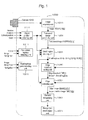
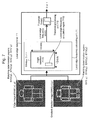
- Figure 1 is a block diagram of a vehicle-mounted object detection device 1000 in the first embodiment.
- the vehicle-mounted object detection device 1000 which is an obstacle detection device, is incorporated in a camera 1010, which is an image pick-up device, mounted on an automobile, an integrated controller, or the like and used for detecting an obstacle such as a pedestrian set in advance from the inside of an image of the outside of an own vehicle picked up by the camera 1010.
- the vehicle-mounted object detection device 1000 is configured to detect a pedestrian from the inside of an image obtained by picking up an image in front of the own vehicle.
- the vehicle-mounted object detection device 1000 includes a computer including a CPU, a memory, and an I/O.
- the vehicle-mounted object detection device 1000 is programmed with predetermined processing and repeatedly executes the processing at a period set in advance.
- the vehicle-mounted object detection device 1000 includes, as shown in Figure 1 , an image acquiring unit 1011, a processed image generating unit 1021, a small region dividing unit 1031, an edge threshold setting unit 1041, an edge extracting unit 1051, an obstacle recognizing unit 1061, and a recognition result output unit 1071 and further includes, depending on an embodiment, an object position detecting unit 1111, an own vehicle lighting detecting unit 1211, and a road surface paint detecting unit 1311.
- the image acquiring unit 1011 captures an image obtained by photographing the outside of the own vehicle from the camera 1010 attached to a position where the camera 1010 can pick up an image of the outside of the own vehicle including the front of the own vehicle and writes the image on a RAM as an image IMGSRC[x][y].
- the image IMGSRC[x][y] is a two-dimensional array and x and y respectively indicate coordinates of the image.
- the processed image generating unit 1021 generates a processed image IMGPROC[x][y] for detecting a pedestrian, who is an obstacle, from the inside of the image IMGSRC[x][y].
- the processed image IMGPROC[x][y] is an image obtained by enlarging or reducing a part of the image IMGSRC[x][y] with a predetermined coefficient. Details of the processing are explained later.
- the small region dividing unit 1031 divides the processed image IMGPROC[x][y] into plural small regions (SXR[r], SYR[r], EXR[r], EYR[r]).
- r represents an ID number of the small region.
- the edge threshold setting unit 1041 determines an edge threshold THR[r] for each of the small regions from pixel values of the processed image IMGPROC[x][y] in the small regions (SXR[r], SYR[r], EXR[r], EYR[r]). Details of setting of the threshold are explained later.
- the edge extracting unit 1051 calculates gray gradient values in the small regions of the processed image IMGPROC[x][y] and generates a binary edge image EDGE[x][y] and a gradient direction image DIRC[x][y] having information concerning the direction of an edge using the edge threshold THR[r] of a small region corresponding thereto. Details of the processing are explained later.
- the obstacle recognizing unit 1061 sets, in the edge image EDGE[x][y], matching determination regions (SXG[g], SYG[g], EXG[g], EYG[g]) for performing obstacle determination (e.g., pedestrian determination) and determines, using the edge image EDGE[x][y] in the matching determination regions and the gradient direction image DIRC[x][y] in a region of a position corresponding thereto.
- g represents an ID number given when plural regions are set. Details of the recognition processing are explained later.
- the recognition result output unit 1071 performs, on the basis of a determination result of the obstacle recognizing unit 1061, output for changing a function of a vehicle according to obstacle information including at least a relative distance PYO[b] between an obstacle such as a recognized pedestrian and the vehicle.
- the recognition result output unit 1071 outputs a position (the relative distance PYO[b], a lateral position PXO[b], and lateral width WDO[b]) of the recognized pedestrian.
- b represents an ID number given when plural objects are detected.
- the object position detecting unit 1111 acquires a detection signal from a radar, which is an obstacle detecting unit that detects an object around the own vehicle, such as a millimeter wave radar or a laser radar mounted on the own vehicle and detects the position of an obstacle present in front of the own vehicle. For example, as shown in Figure 3 , the object position detecting unit 1111 acquires a position (a relative distance PY[b], a lateral position PX[b], and lateral width WD[b]) of an obstacle such as a pedestrian 32 around the vehicle from the radar.
- b represents an ID number given when plural objects are detected.
- Position information of these objects may be acquired by directly inputting a signal of the radar to the vehicle-mounted object detection device 1000 or may be acquired by performing communication using the radar and the LAN (Local Area Network).
- the object position detected by the object position detecting unit 1111 is used by the processed image generating unit 1021 and the small region dividing unit 1031.
- the own vehicle lighting detecting unit 1211 determines whether the own vehicle has its lamps on and, if the own vehicle has its lamps on, outputs "1" and, otherwise, outputs "0". As the lighting determination, whether the lamps are on may be determined by directly inputting a signal of a light switch or a signal of the light switch may be acquired by performing communication using the LAN (Local Area Network) to determine whether the lamps are on. Whether the lamps are on may be determined using light and shade of an image acquired by the image acquiring unit 1011. For example, when the lamps are on, the inside of a lighted range appears bright and the outside of the range appears dark.
- the road surface paint detecting unit 1311 detects a road surface paint on a pedestrian crossing or the like present in front of the own vehicle.
- a road surface paint there is a method of acquiring information concerning navigation through communication using the LAN (Local Area Network), acquiring, for example, information concerning a crossing with a traffic light, and acquiring a distance from the own vehicle to the pedestrian crossing.
- the road surface paint detecting unit 1311 may determine the road paint using light and shade of an image acquired by the image acquiring unit 1011. For example, since the road paint on the pedestrian crossing or the like is white, an image of the road surface paint is picked up bright on the image. Therefore, the road surface paint can be detected by means explained below.
- the road surface paint detecting unit 1311 calculates, using a camera image and a camera geometric model, a road surface region of the image on the image and extracts pixels in which luminance values of the road surface region is equal to or larger than a threshold TH_GBright. Subsequently, the road surface paint detecting unit 1311 groups the extracted pixels into groups of the pixels adjacent to one another and acquires, from a region where an area is a threshold TH_GArea among the grouped regions, a y coordinate Y_Gmin at the upper end on the image of a region present at the highest position on the image. Further, the road surface paint detecting unit 1311 calculates a distance from the own vehicle to the position of Y_Gmin using a camera geometry. According to the processing explained above, it is possible to calculate a distance from the own vehicle to the road surface paint. An output of the road surface paint detecting unit 1311 is used by the small region dividing unit 1031.
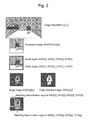
- FIG. 2 is a diagram showing, using an example, the images and the regions used in the above explanation.
- the processed image IMGPROC[x][y] is generated from the image IMGSRC[x][y].
- the edge image EDGE[x][y] and the gradient direction image DIRC[x][y] are generated from the processed image IMGPROC[x][y].
- the small regions (SXR[r], SYR[r], EXR[r], EYR[r]) are set to divide the processed image IMGPROC[x][y].
- the matching determination regions (SXG[g], SYG[g], EXG[g], EYG[g]) are regions having a determined size in the edge image EDGE[x][y] and the gradient direction image DIRC[x][y].
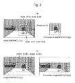
- Figure 3 shows an example of the processing by the processed image generating unit.
- the processed image generating unit 1021 selects a region where pedestrian detection processing is performed in the image IMGSRC[x][y], calculates a range of coordinates of the region, a start point SXP and an end point EXP on an x coordinate (the lateral direction) and a start point SYP and an end point EYP on a y coordinate (the longitudinal direction), and generates the processed image IMGPROC[x][y] from the region.
- the processed image generating unit 1021 may use or may not use the object position detecting unit 1111. First, processing performed when the object position detecting unit 1111 is used in the processed image generating unit 1021 is explained.
- Figure 3(a) is an example of the processing by the processed image generating unit performed when the object position detecting unit 1111 is used.
- the processed image generating unit 1021 calculates, from the relative distance PY[b], the lateral position PX[b], and the lateral width WD[b] of an obstacle detected by the object position detecting unit 1111, a position on an image of the detected obstacle (a start point SXB and an end point EXB on the x coordinate (the lateral direction) and a start point SYB and an end point EYB on the y coordinate (the longitudinal direction)). If camera geometric parameters that associate coordinates on a camera image and a positional relation in the real world are calculated in advance by a method such as camera calibration and the height of an object is assumed as, for example, 180 [cm] in advance, a position on the image is uniquely determined.
- an object position (SXP, EXP, SYP, EYP) obtained by correcting an object position (SXB, EXB, SYB, EYB) on the image is calculated.
- the correction expands a region by a predetermined amount or moves the region. For example, SXB, EXB, SYB, and EYB are expanded up and down and to the left and right by a predetermined number of pixels.
- the processed image generating unit 1021 slices out the image IMGSRC[x][y] surrounded by the corrected object position (SXP, EXP, SYP, EYP) and enlarges or reduces the size of the object in the image to a predetermined size to thereby generate the processed image IMGPROC[x][y].
- the processed image generating unit 1021 enlarges or reduces the image using the camera geometry such that all objects having height of 180 [cm] and width of 60 [cm] have a size of 16 dots x 12 dots in the processed image IMGPROC[x][y].
- the processed image generating unit 1021 when the object position detecting unit 1111 is used, the processed image generating unit 1021 generates the processed image IMGPROC[x][y] on the basis of the image IMGSRC[x][y] acquired from the image acquiring unit 1011 and the position of the obstacle detected by the object position detecting unit 1111.
- the processed image generating unit 1021 When the processing is applied to plural regions, the processed image generating unit 1021 generates processed images IMGPROC[x][y] of the regions and separately carries out, for the respective processed images, processing by a division boundary setting unit to processing by an obstacle recognizing unit explained below.
- a method of selecting a region when the object position detecting unit 1111 is not used for example, there are a method of setting a region to search through an entire image while changing the size of a region and a method of setting a region while limiting the region to a specific position and a specific size.
- a method of limiting using, for example, own vehicle speed, the region to a position to where the own vehicle advances after T seconds.
- Figure 3(b) is an example of a search for a position to where the own vehicle advances after 2.3 seconds.
- the processed image generating unit 1021 calculates a range (SYP2, EYP2) in the y direction on the image IMGSRC[x][y] using the camera geometric parameters from road surface height (0 cm) at a relative distance to the position to where the own vehicle advances after 2.3 seconds and assumed height of a pedestrian (in this embodiment, 180 cm).
- a range (SXP2, EXP2) in the x direction may not be limited or may be limited according to, for example, a predicted route of the own vehicle.
- the processed image generating unit 1021 slices out the image IMGSRC[x][y] surrounded by the corrected object position (SXP, EXP, SYP, EYP) and enlarges or reduces the size of the object in the image to a predetermined size to thereby generate the processed image IMGPROC[x][y].
- the processed image generating unit 1021 enlarges or reduces the image using the camera geometry such that all objects having height of 180 [cm] and width of 60 [cm] have a size of 16 dots x 12 dots in the processed image IMGPROC[x][y].
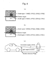
- Figure 4 is a division example of the small region dividing unit 1031.
- Figure 5 is a flowchart in this embodiment of the small region dividing unit 1031.
- a system for division into small regions three kinds of dividing methods are explained: a system using the object position detecting unit 1111 and the own vehicle lighting detecting unit 1211, a system using the road surface paint detecting unit 1311, and a system not using any of the object position detecting unit 1111, the own vehicle lighting detecting unit 1211, and the road surface paint detecting unit 1311.
- a method of selecting the three systems according to an illumination state on the outside of the vehicle is explained.
- the small region 1 and the small region 2 may be set without a gap as shown in Figure 4(a) .
- hysteresis of about five pixels may be provided with division height VPY on the image as a boundary to prevent an edge due to a difference in an illumination state from occurring.
- all edges in the portion of the hysteresis are set to zero.
- the small region dividing unit 1031 calculates light illumination height LZ for an object according to Equation (1) below from the relative distance PY[b] of the obstacle detected by the object position detecting unit 1111, an illumination angle LANGL of the light of the own vehicle, and light height LHEIGHT of the own vehicle.
- LZ LHEIGHT - PY b ⁇ tan LANGL
- the illumination angle LANGL of the light of the own vehicle and the light height LHEIGHT of the own vehicle are values set in advance according to a type of a vehicle.
- the small region 1 and the small region 2 may be set without a gap as shown in Figure 4(a) .
- hysteresis of about five pixels may be provided with division height LZY on the image as a boundary to prevent an edge due to light from occurring.
- all edges in the portion of the hysteresis are set to zero.
- the small region dividing unit 1031 divides the processed image IMGPROC[x][y] into upper and lower images with the position of detected road surface paint as a boundary.
- the small region 1 and the small region 2 may be set without a gap as shown in Figure 4(a) .
- hysteresis of about five pixels may be provided with division height PZY on the image as a boundary to prevent an edge due to a difference in an illumination state from occurring.
- all edges in the portion of the hysteresis are set to zero.
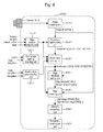
- Figure 5 is a flowchart describing switching conditions for the three division systems.
- step 51 the small region dividing unit 1031 determines, using an output of the own vehicle lighting detecting unit 1211, whether the own vehicle has its lamps on. When it is determined that the own vehicle has its lamps on, the small region dividing unit 1031 selects the second dividing means. When the own vehicle does not have its lamps on, the small region dividing unit 1031 shifts to the next step.
- the small region dividing unit 1031 determines, using an output of the road surface paint detecting unit 1311, whether road surface paint is present in front of the own vehicle. When it is determined that road surface paint is present in front of the own vehicle, the small region dividing unit 1031 selects the third dividing means. When it is determined that road surface paint is absent, the small region dividing unit 1031 selects the first dividing means.
- the small region dividing unit 1031 determines that a part of a pedestrian is lit up by the headlamp of the own vehicle, selects the second dividing means, and can divide a processed image into a region where the headlamps are emitting light and a dark region.
- the small region dividing unit 1031 determines that the lower half body of a pedestrian standing on the road surface paint appears bright, selects the third dividing means, and can divide a processed image into a bright region including the road surface paint and a region without the road surface paint.
- the small region dividing unit 1031 selects the first dividing means. Even when the road surface is reflected by backlight and appears bright, the first dividing means can divide the processed image into a region bright with backlight and a region where the road surface does not appear.
- the road surface paint detecting unit 1311 only has to include at least the first dividing means and does not need to include all the three dividing means.
- the conditional branch shown in Figure 5 follows the route of NO.
- the edge threshold setting unit 1041 determines the edge threshold THR[r] according to an average AVE[r] and a variance VAR[r] of gray values in the small regions SXR[r], SYR[r], EXR[r], and EYR[r] of the processed image IMGPROC[x][y].
- r is an ID number of the small region.
- the edge threshold is determined by, for example, a method of using a table having the average AVE[r] of gray values as an argument or a method of using a two-dimensional map having the average AVE[r] and the variance [r] of gray values as arguments.
- a threshold of an optimum edge in images having various kinds of brightness is manually determined in advance and averages and variances at that point formed as a map are used. Consequently, it is possible to determine an optimum threshold from the average AVE[r] and the variance VAR[r] of gray values in the small regions.
- an average and a variance of pixel values of an image obtained as a result of applying, for example, a Sobel filter for the processed image IMGPROC[x][y] may be used rather than gray values.
- An arithmetic operation of the Soble filter is explained later.
- the edge extracting unit 1051 applies a differential filter such as a Sobel filter to the processed image IMGPROC[x][y] to calculate the intensity and the direction of the gradient of an image and subjects the intensity of the gradient to threshold processing to thereby extract an edge.
- a differential filter such as a Sobel filter
- the Sobel filter is applied as the differential filter.
- the Sobel filter has a size of 3x3 as shown in Figure 6 .
- Two kinds of filters are present: an x direction filter 61 that calculates a gradient in the x direction and a y direction filter 62 that calculates a gradient in the y direction.
- the edge extracting unit 1051 performs, for each pixel of the processed image IMGPROC[x][y], a product-sum operation of pixel values of nine pixels in total including the pixel and eight pixels around the pixel and weight of the x direction filter 61 in a position corresponding to the pixel.
- a result of the product-sum operation is a gradient in the x direction in the pixel.
- Calculation of a gradient in the y direction is the same.
- a gradient intensity image DMAG[x][y] and a gradient direction image DIRC[x][y] are calculated by Equations (2) and (3) below.
- DMAG[x][y] and DIRC[x][y] are two-dimensional arrays having the same size as the processed image IMGPROC[x][y].
- a coordinate x, y of the DRAM[x][y] and DIRC[x][y] corresponds to a coordinate of IMGPROC[x][y].
- the edge extracting unit 1051 calculates, concerning all pixels in the small regions SXR[r], SYR[r], EXR[r], and EYR[r] in the processed image IMGPROC[x][y], the gradient intensity image DMAG[x][y] and the gradient direction image DIRC[x][y]. Subsequently, the edge extracting unit 1051 compares the edge threshold THR[r] and DMAG[x][y] according to the small regions SXR[r], SYR[r], EXR[r], and EYR[r] to which the calculated DMAG[x][y] belongs.
- the edge extracting unit 1051 stores 1 in the edge image EDGE[x][y]. Otherwise, the edge extracting unit 1051 stores 0 in the edge image EDGE[x][y].
- the edge image EDGE[x][y] is a two-dimensional array having the same size as the image IMGSRC[x][y].
- the coordinate x, y of EDGE[x][y] corresponds to the coordinate of IMGSRC[x][y].
- the small region dividing unit 1031 divides the processed image IMGPROC[x][y] including the object into the small regions (SXR[r], SYR[r], EXR[r], and EYR[r]) according to an illumination state on the outside of the vehicle.
- the edge threshold setting unit 1041 sets the edge threshold THR[r] for each of the small regions and extracts an edge using the edge threshold THR[r] for each of the small regions. Consequently, even in a scene in which a part of a pedestrian appears bright, it is possible to correctly extract edges of a contour of the pedestrian in a bright region and a dark region.
- the obstacle recognizing unit 1061 sets the matching determination regions (SXG[g], SYG[g], EXG[g], EYG[g]) for performing pedestrian determination in the edge image EDGE[x][y].
- SXG[g], SYG[g], EXG[g], EYG[g] the matching determination regions for performing pedestrian determination in the edge image EDGE[x][y].
- an image is enlarged or reduced using the camera geometry such that all objects having height of 180 [cm] and width of 60 [cm] have a size of 16 dots x 12 dots in the processed image IMGPROC[x][y].
- the obstacle recognizing unit 1061 sets plural matching determination regions to be laid at a fixed interval in the edge image EDGE[x][y]. Concerning each of the matching determination regions (SXG[g], SYG[g], EXG[g], EYG[g]), the obstacle recognizing unit 1061 performs determination using a discriminator 81 explained in detail below and, if there is a place where an output of the discriminator 81 is 1, determines that a pedestrian is present in the position.
- Examples of a method of detecting a pedestrian through image processing include a method by template matching for preparing plural representative templates of pedestrian patterns and performing a differential cumulative operation or a normalization correlation operation to calculate a degree of coincidence and a method of performing pattern recognition using a discriminator such as a neural network. Irrespective of which of the methods is adopted, a database of sources serving as indexes for determining whether an obstacle is a pedestrian in advance is necessary. Patterns of various pedestrians are stored as a database and a representative template is created and a discriminator is generated from the database. In an actual environment, pedestrians in various clothes, postures, and body shapes are present and conditions such as illumination and weather are different. Therefore, it is necessary to prepare a large number of databases and reduce misdeterminations. In detecting a pedestrian, the former method by the template matching is not realistic because the number of templates is enormous if determination omission is prevented.
- the latter method of determining a pattern using the discriminator is adopted.
- the size of the discriminator does not depend on the size of a database of sources.
- a database for generating the discriminator is referred to as teacher data.
- the discriminator 81 used in this embodiment determines whether an obstacle is a pedestrian on the basis of plural local edge determiners.
- the local edge determiner is explained using an example shown in Figure 7 .
- a local edge determiner 71 is a determiner that receives input of the edge image EDGE[x][y], the gradient direction image DIRC[x][y], and the matching determination regions (SXG[g], SYG[g], EXG[g], EYG[g]) and outputs a binary value 0 or 1.
- the local edge determiner 71 includes a local edge frequency calculating unit 711 and a threshold processing unit 712.
- the local edge frequency calculating unit 711 has a local edge frequency calculation region 7112 in a window 7111 having the same size as the matching determination region (SXG[g], SYG[g], EXG[g], EYG[g]).
- the local edge frequency calculating unit 711 sets, from a positional relation between the matching determination region (SXG[g], SYG[g], EXG[g], EYG[g]) and the window 7111, positions where a local edge frequency is calculated in the edge image EDGE[x][y] and the gradient direction image DIRC[x][y] and calculates a local edge frequency MWC.
- the local edge frequency MWC is a total number of pixels in which an angle value of the gradient direction image DIRC[x][y] satisfies an angle condition 7113 and the edge image EDGE[x][y] in a position corresponding thereto is 1.
- the angle condition 7113 is a condition that the angle value is between 67.5 degrees to 112.5 degrees or between 267.5 degrees and 292.5 degrees and is a condition for determining whether a value of the gradient direction image DIRC[x][y] is in a fixed range.
- the threshold processing unit 712 has a threshold THWC set in advance. If the local edge frequency MWC calculated by the local edge frequency calculating unit 711 is equal to or higher than the threshold THWC, the threshold processing unit 712 outputs 1. Otherwise, the threshold processing unit 712 outputs 0. If the local edge frequency MWC calculated by the local edge frequency calculating unit 711 is equal to or lower than the threshold THWC, the threshold processing unit 712 may output 1. Otherwise, the threshold processing unit 712 may output 0.
- the discriminator 81 receives input of the edge image EDGE[x][y], the gradient direction image DIRC[x][y], and the matching determination regions (SXG[g], SYG[g], EXG[g], EYG[g]). If a pedestrian is present in the regions, the discriminator 81 outputs 1. If a pedestrian is absent in the regions, the discriminator 81 outputs 0.
- the discriminator 81 includes forty local edge frequency determiners 8101 to 8140, a totaling unit 812, and a threshold processing unit 813.
- Each kind of processing by the local edge frequency determiners 8101 to 8140 is the same as the processing by the local edge determiner 71.
- the local edge frequency calculation region 7112, the angle condition 7113, and the threshold THWC are respectively different from those of the local edge determiner 71.
- the totaling unit 812 multiplies outputs from the local edge frequency determiners 8101 to 8140 with weights WWC1 to WWC40 corresponding thereto and outputs a total of the outputs multiplied with the weights WWC1 to WWC40.
- the threshold processing unit 813 has a threshold THSC. If an output of the totaling unit 812 is larger than the threshold THSC, the threshold processing unit 813 outputs 1. Otherwise, the threshold processing unit 813 outputs 0.
- the local edge frequency calculation region 7112, the angle condition 7113, the threshold THWC, the weights WWC1 to WWC40, and the final threshold THSC, which are parameters of the local edge frequency determiners of the discriminator 81, are adjusted using the teacher data such that 1 is output when an input image to the discriminator is a pedestrian and 0 is output when the input image is not a pedestrian.
- Means for machine learning such as AdaBoost may be used for the adjustment or the adjustment may be performed manually.
- the local edge frequency determiner is represented as cWC[m].
- m is an ID number of the local edge frequency determiner.
- Each of the local edge frequency determiners cWC[m] calculates values of the local edge frequency MWC from all teacher data and determines the threshold THWC for each of the values.
- the threshold THWC a value that can best classify teacher data of pedestrians and teacher data of non-pedestrians is selected.
- nPD is an ID number of the teacher data of the pedestrians
- nBG is an ID number of the teacher data of the non-pedestrians.
- the discriminator 81 With k set to 1, thereafter, the discriminator 81 repeatedly performs processing. First, the discriminator 81 normalizes weight such that a total of the weights of the teacher data of all the pedestrians and non-pedestrians is 1. Subsequently, the discriminator 81 calculates error detection ratios cER[m] of the local edge frequency determiners.
- the error detection ratio cER[m] is, in the local edge frequency determiner cWC[m], a total of weights of the teacher data of the pedestrians, outputs of which are 0 when the teacher data of the pedestrians is input to the local edge frequency determiner cWC[m], or the teacher data of the non-pedestrians, outputs of which are 1 when the teacher data of the non-pedestrians is input to the local edge frequency determiner cWC[m], i.e., teacher data, outputs of which are wrong.
- the discriminator 81 After calculating the error detection ratios cER[m] of all the local edge frequency determiners, the discriminator 81 selects ID mMin of the local edge frequency determiner having a minimum error detection ratio and sets a final local edge frequency determiner WC[k] equal to cWC[mMin].
- the discriminator 81 repeats the processing until k reaches a value set in advance (e.g., 40).
- the final local edge frequency determiner WC obtained after the end of the repeated processing is the discriminator 81 automatically adjusted by AdaBoost.
- the weights WWC1 to WWC40 are calculated from 1/BT[k] and the threshold THSC is set to 0.5.
- the obstacle recognizing unit 1061 can detect a pedestrian using edges of a contour of the pedestrian extracted by the edge extracting unit 1051.
- the discriminator 81 used for detection of a pedestrian is not limited to the method explained in this embodiment. Template matching using normalized correlation, a neural network discriminator, a support vector machine discriminator, a Bayes discriminator, and the like may be used.
- the dividing means of the small region dividing unit 1031 are not limited to the three dividing means in this embodiment and may be two or less or four or more dividing means.
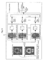
- FIG. 9 is a block diagram representing the embodiment of the vehicle-mounted object detection device 2000.
- the same components are denoted by the same reference numerals and signs and explanation of the components is omitted.
- the vehicle-mounted object detection device 2000 is incorporated in a camera mounted on an automobile, an integrated controller, or the like and used for detecting an obstacle from the inside of an image picked up by the camera.
- the vehicle-mounted object detection device 2000 is configured to detect a pedestrian from the inside of an image obtained by picking up an image around an own vehicle.
- the vehicle-mounted object detection device 2000 includes a computer including a CPU, a memory, and an I/O.
- the vehicle-mounted object detection device 2000 is programmed with predetermined processing and repeatedly executes processing at a period set in advance.
- the vehicle-mounted object detection device 2000 includes, as shown in Figure 9 , the image acquiring unit 1011, a processed region setting unit 2021, a small region dividing unit 2031, an edge threshold setting unit 2041, an edge extracting unit 2051, an obstacle recognizing unit 2061, and the recognition result output unit 1071 and further includes, depending on an embodiment, the object position detecting unit 1111, the own vehicle lighting detecting unit 1211, and the road surface paint detecting unit 1311.
- the processed region setting unit 2021 sets a processed region (SXP, SYP, EXP, EYP) where a pedestrian, who is an obstacle, is detected from the inside of the image IMGSRC[x][y]. Details of the setting are explained later.
- the small region dividing unit 2031 divides the processed region (SXP, SYP, EXP, EYP) of the image IMGSRC[x][y] into plural small regions (SXR[r], SYR[r], EXR[r], EYR[r]).
- r is an ID number of the small region.
- the edge threshold setting unit 2041 determines the edge threshold THR[r] from pixel values of the image IMGSRC[x][y] in the small regions (SXR[r], SYR[r], EXR[r], EYR[r]). Details of setting of the threshold are explained later.
- the edge extracting unit 2051 calculates gray gradient values in the small regions of the image IMGSRC[x][y] and generates, using the edge threshold THR[r] of a small region corresponding thereto, the binary edge image EDGE[x][y] and the gradient direction image DIRC[x][y] having information concerning the direction of an edge. Details of the processing are explained later.
- the obstacle recognizing unit 2061 sets, in the edge image EDGE[x][y], the matching determination regions (SXG[g], SYG[g], EXG[g], EYG[g]) for performing pedestrian determination and determines presence or absence of a pedestrian using the edge image EDGE[x][y] in the matching determination regions and the gradient direction image DIRC[x][y] in a region of a position corresponding thereto.
- g represents an ID number given when plural regions are set. Details of the recognition processing are explained later.
- the processed region setting unit 2021 selects a region where pedestrian detection processing is performed in the image IMGSRC[x][y] and calculates a range of coordinates of the region, the start point SXP and the end point EXP on the x coordinate (the lateral direction) and the start point SYP and the end point EYP on the y coordinate (the longitudinal direction).
- the processed region setting unit 2021 may use or may not use the object position detecting unit 1111. First, processing performed when the object position detecting unit 1111 is used in the processed region setting unit 2021 is explained.
- the processed region setting unit 2021 calculates, from the relative distance PY[b], the lateral position PX[b], and the lateral width WD[b] of an object detected by the object position detecting unit 1111, a position on an image of the detected object (the start point SXB and the end point EXB on the x coordinate (the lateral direction) and the start point SYB and the end point EYB on the y coordinate (the longitudinal direction)). If camera geometric parameters that associate coordinates on a camera image and a positional relation in the real world are calculated in advance by a method such as camera calibration and the height of an object is assumed as, for example, 180 [cm] in advance, a position on the image is uniquely determined.
- the object position (SXP, EXP, SYP, EYP) obtained by correcting the object position (SXB, EXB, SYB, EYB) on the image is calculated.
- the correction expands a region by a predetermined amount or moves the region. For example, SXB, EXB, SYB, and EYB are expanded up and down and to the left and right by a predetermined number of pixels. An object position obtained as a result of this correction is set as the processed region (SXP, EXP, SYP, EYP).
- the processed region (SXP, EXP, SYP, EYP) is set for each of the regions.
- the processing by the small region dividing unit to the processing by the obstacle recognizing unit are individually carried out on respective processed images.
- a method of selecting a region when the object position detecting unit 1111 is not used for example, there are a method of setting a region to search through an entire image while changing the size of a region and a method of setting a region while limiting the region to a specific position and a specific size.
- a method of limiting using, for example, own vehicle speed, the region to a position to where the own vehicle advances after T seconds.
- Figure 3(b) is an example of searching for, using own vehicle speed, a position to where the own vehicle advances after 2.3 seconds.
- the processed region setting unit 2021 calculates the range (SYP2, EYP2) in the y direction on the image IMGSRC[x][y] using the camera geometric parameters from road surface height (0 cm) at a relative distance to the position to where the own vehicle advances after 2.3 seconds and assumed height of a pedestrian (in this embodiment, 180 cm).
- the range (SXP2, EXP2) in the x direction may not be limited or may be limited according to, for example, a predicted route of the own vehicle.
- a region (SXP2, SYP2, EXP2, EYP2) obtained as a result of this processing is set as the processed region (SXP, EXP, SYP, EYP).
- a system for division into small regions three kinds of dividing methods are explained: a system using the object position detecting unit 1111 and the own vehicle lighting detecting unit 1211, a system using the road surface paint detecting unit 1311, and a system not using all of the object position detecting unit 1111, the own vehicle lighting detecting unit 1211, and the road surface paint detecting unit 1311.
- a method of selecting the three systems according to an illumination state on the outside of the vehicle is explained.
- the small region 1 and the small region 2 may be set without a gap as shown in Figure 4(a) .
- hysteresis of about five pixels may be provided with the division height VPY on the image as a boundary to prevent an edge due to a difference in an illumination state from occurring.
- all edges in the portion of the hysteresis are set to zero.
- the small region dividing unit 2031 calculates the light illumination height LZ for an object according to Equation (1) above from the relative distance PY[b] of the object detected by the object position detecting unit 1111, the illumination angle LANGL of the light of the own vehicle, and light height LHEIGHT of the own vehicle.
- the illumination angle LANGL of the light of the own vehicle and the light height LHEIGHT of the own vehicle are values set in advance according to a type of a vehicle.
- the small region 1 and the small region 2 may be set without a gap as shown in Figure 4(a) .
- hysteresis of about five pixels may be provided with division height LZY on the image as a boundary to prevent an edge due to light from occurring.
- all edges in the portion of the hysteresis are set to zero.
- the small region dividing unit 2031 divides the processed region (SXP, EXP, SYP, EYP) in the image IMGSRC[xx][y] into upper and lower images with the position of detected road surface paint as a boundary.
- the small region 1 and the small region 2 may be set without a gap as shown in Figure 4(a) .
- hysteresis of about five pixels may be provided with the division height PZY on the image as a boundary to prevent an edge due to a difference in an illumination state from occurring.
- all edges in the portion of the hysteresis are set to zero.
- Figure 5 is a flowchart describing switching conditions for the three division systems.
- step 51 the small region dividing unit 2031 determines, using an output of the own vehicle lighting detecting unit 1211, whether the own vehicle has its lamps on. When it is determined that the own vehicle has its lamps on, the small region dividing unit 2031 selects the second dividing means. When the own vehicle does not have its lamps on, the small region dividing unit 2031 shifts to the next step.
- the small region dividing unit 2031 determines, using an output of the road surface paint detecting unit 1311, whether road surface paint is present in front of the own vehicle. When it is determined that road surface paint is present in front of the own vehicle, the small region dividing unit 2031 selects the third dividing means. When it is determined that road surface paint is absent, the small region dividing unit 2031 selects the first dividing means.
- the small region dividing unit 2031 determines that a part of a pedestrian is lit up by the headlamp of the own vehicle and selects the second dividing means.
- the second dividing means can divide a processed image into a region which the headlamps are illuminating and a dark region.
- the small region dividing unit 2031 determines that the lower half body of a pedestrian standing on the road surface paint appears bright and selects the third dividing means.
- the third dividing means can divide the processed image into a bright region including the road surface paint and a region without the road surface paint.
- the small region dividing unit 2031 selects the first dividing means. Even when the road surface is reflected by backlight and appears bright, the first dividing means can divide the processed image into a region bright with backlight and a region where the road surface does not appear.
- the road surface paint detecting unit 1311 only has to include at least the first dividing means and does not need to include all the three dividing means.
- the conditional branch shown in Figure 5 follows the route of NO.
- the edge threshold setting unit 2041 determines the edge threshold THR[r] according to the average AVE[r] and the variance VAR[r] of gray values in the small regions SXR[r], SYR[r], EXR[r], and EYR[r] of the image IMGSRC[x][y] acquired by the image acquiring unit 1011.
- r is an ID number of the small region.
- the edge threshold is determined by, for example, a method of using a table having the average AVE[r] of gray values as an argument or a method of using a two-dimensional map having the average AVE[r] and the variance VAR[r] of gray values as arguments.
- a threshold of an optimum edge in images having various kinds of brightness is manually determined in advance and averages and variances at that point converted into a map are used. Consequently, it is possible to determine an optimum threshold from the average AVE[r] and the variance VAR[r] of gray values in the small regions.
- an average and a variance of pixel values of an image obtained as a result of applying, for example, a Sobel filter for the image IMGSRC[x][y] may be used rather than gray values.
- An arithmetic operation of the Soble filter is explained later.
- the edge extracting unit 2051 applies a differential filter such as a Sobel filter to the image IMGSRC[x][y] acquired by the image acquiring unit 1011 to calculate the intensity and the direction of the gradient of an image and subjects the intensity of the gradient to threshold processing to thereby extract an edge.
- a differential filter such as a Sobel filter
- the Sobel filter is applied as the differential filter.
- the Sobel filter has a size of 3x3 as shown in Figure 6 .
- Two kinds of filters are present: the x direction filter 61 that calculates a gradient in the x direction and the y direction filter 62 that calculates a gradient in the y direction.
- the edge extracting unit 2051 performs, for each pixel of the image IMGSRC[x][y], a product-sum operation of pixel values of nine pixels in total including the pixel and eight pixels around the pixel and weight of the x direction filter 61 in a position corresponding to the pixel.
- a result of the product-sum operation is a gradient in the x direction in the pixel.
- DMAG[x][y] and DIRC[x][y] are two-dimensional arrays having the same size as the image IMGSRC[x][y].
- a coordinate x, y of the DMAG[x][y] and DIRC[x][y] corresponds to a coordinate of the image IMGSRC[x][y].
- the edge extracting unit 2051 calculates, concerning all pixels in the small regions SXR[r], SYR[r], EXR[r], and EYR[r] in the image IMGSRC[x][y], the gradient intensity image DMAG[x][y] and the gradient direction image DIRC[x][y]. Subsequently, the edge extracting unit 2051 compares the edge threshold THR[r] and DMAG[x][y] according to the small regions SXR[r], SYR[r], EXR[r], and EYR[r] to which the calculated DMAG[x] [y] belongs.
- the edge extracting unit 2051 stores 1 in the edge image EDGE[x][y]. Otherwise, the edge extracting unit 2051 stores 0 in the edge image EDGE[x][y].
- the edge image EDGE[x][y] is a two-dimensional array having the same size as the image IMGSRC[x][y].
- the coordinate x, y of EDGE[x][y] corresponds to the coordinate of the image IMGSRC[x][y].
- the small region dividing unit 2031 divides the processed region (SXP, SYP, EXP, EYP) in the image IMGSRC[x][y] including an object into the small regions (SXR[r], SYR[r], EXR[r], and EYR[r]) according to an illumination state on the outside of the vehicle.
- the edge threshold setting unit 2041 sets the edge threshold THR[r] for each of the small regions and the edge extracting unit 2051 extracts an edge using the edge threshold THR[r] for each of the small regions. Consequently, even in a scene in which a part of a pedestrian appears bright, it is possible to correctly extract edges of a contour of the pedestrian in a bright region and a dark region.
- the obstacle recognizing unit 2061 sets the matching determination regions (SXG[g], SYG[g], EXG[g], EYG[g]) for performing pedestrian determination in the edge image EDGE[x][y].
- a method of determining the width WG and the height HG can be uniquely determined according to the camera geometry using a distance to the object and vanishing point when the vehicle-mounted object detection device 2000 includes the object position detecting unit 1111 or when the distance to the object is provisionally determined.
- the obstacle recognizing unit 2061 fixes an aspect ratio of the matching determination region and sets the size of the matching determination region while changing the size.
- the processed region SXP, SYP, EXP, EYP
- the matching determination regions SXG[g], SYG[g], EXG[g], EYG[g]
- the obstacle recognizing unit 2061 sets plural matching determination regions to be laid at a fixed interval in the edge image EDGE[x][y].
- the obstacle recognizing unit 2061 performs determination using a discriminator 82 concerning the respective matching determination regions (SXG[g], SYG[g], EXG[g], EYG[g]). If there is a place where an output of the discriminator 82 is 1, the obstacle recognizing unit 2061 determines that a pedestrian is present in the position.
- the discriminator 82 used in this embodiment determines whether an obstacle is a pedestrian on the basis of plural local edge determiners.
- the discriminator 82 in this embodiment has the same configuration as the discriminator 81. However, whereas, in the discriminator 81, the size of the window 7111 in the local edge frequency determiners 8101 to 8140 is the width of 12 dots and the height of 16 dots, the discriminator 82 enlarges or reduces the size of the window 7111 to be the same as the width WG and the height HG of the matching determination region. According to the enlargement or the reduction of the window 7111, the discriminator 82 enlarges or reduces the local edge frequency calculation region 7112 in the window 7111 at the same ratio. Processing after this is the same as that of the discriminator 81. Detailed explanation of the processing is omitted.
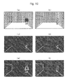
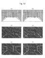
- Figures 10(a) and 10(b) are examples of objects, on parts of which light from the headlamp of the own vehicle is incident.
- (a) is a pedestrian and
- (b) is a signboard.
- edges shown in Figures 10(c) and 10(d) are respectively obtained and cannot be distinguished.
- edges are extracted as shown in Figures 10(e) and 10(f) . Edges of a contour of the pedestrian are correctly extracted.
- the pedestrian shown in Figure 10(a) can be recognized.
- the obstacle recognizing unit 1061 (2061) in the vehicle-mounted object detection device 1000 (or the vehicle-mounted object detection device 2000) does not have to adopt the form including the discriminator 81 (82).
- the discriminator 81 812.
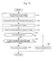
- another embodiment of an obstacle recognizing unit that determines an obstacle according to the length of a continuous vertical edge is explained using Figure 11 .
- Figure 11 is a flowchart representing a flow of processing in the other embodiment of the obstacle recognizing unit.
- the obstacle recognizing unit sets the matching determination regions (SXG[g], SYG[g], EXG[g], EYG[g]).
- the obstacle recognizing unit extracts an edge in the longitudinal direction in edge images EDGE[x][y] in the matching determination regions (SXG[g], SYG[g], EXG[g], EYG[g]).
- the obstacle recognizing unit determines presence or absence of an edge using a value of the edge image EDGE[x][y].
- the edge image EDGE[x][y] is a binary image.
- the edge image EDGE[x][y] indicates that an edge, i.e., a contour of an object is present in the coordinate (x, y) of the image IMGSRC[x][y] corresponding thereto.
- the obstacle recognizing unit determines the direction of the edge using the gradient direction image DIRC[x][y].
- the gradient direction image DIRC[x][y] has a value of 0 to 359 and represents an angle of a light and shade change. Therefore, when a value of the coordinate (x, y) of the edge image EDGE[x][y] is 1, it is possible to learn a direction on an image of a contour of an object by referring to a value of the gradient direction image DIRC[x][y] of the coordinate (x, y) corresponding thereto.
- step 102 can be realized by extracting, for example, a portion where the edge image EDGE[x][y] is 1 and a value of the gradient direction image DIRC[x][y] of the coordinate (x, y) corresponding thereto is in a range of 90 ⁇ 22.5[°] or 270 ⁇ 22.5[°].
- the obstacle recognizing unit stores a result of the extraction in, for example, a vertical edge image VEDGE[x][y].
- the vertical edge image VEDGE[x][y] is a two-dimensional array having the same size as the edge image EDGE[x][y].
- the coordinate x, y of VEDGE[x][y] corresponds to the coordinate of EDGE[x][y].
- "1" is substituted in a pixel in a coordinate that satisfies the above conditions and "0" is substituted in a coordinate that does not satisfy the conditions.
- the obstacle recognizing unit performs grouping of portions where a pixel value is "1" in the vertical edge image VEDGE[x][y]. For the grouping, for example, labeling processing is used.
- the obstacle recognizing unit searches for a place where a pixel value is 1 in the vertical edge image VEDGE[x] [y] and gives a label number 1 to a pixel in the place. Subsequently, if a pixel value of a pixel adjacent to the pixel is 1, the obstacle recognizing unit gives the label number 1 to the pixel as well. The obstacle recognizing unit repeats this processing until all pixels adjacent to the pixels having the label number 1 have a pixel value 0.
- the obstacle recognizing unit gives a label number 2 to one of the pixels and performs processing same as the processing in the case of the label number 1.
- the obstacle recognizing unit repeats the above processing until no pixel having the pixel value 1 to which a label number is not given remains.
- step 104 the obstacle recognizing unit extracts two vertical edges long in the y direction on the image out of the grouped edges.
- the obstacle recognizing unit determines whether the extracted edges are a pair.
- the vertical edge image VEDGE[x][y] and the gradient direction image DIRC[x][y] are used.
- Figure 12 is an example of the pair determination for edges.
- the obstacle recognizing unit calculates an overlapping range (SY_PAIR, EY_PAIR) in the y direction on the image of the two edges extracted in the vertical edge image.
- the obstacle recognizing unit calculates, concerning each of the extracted two edges, averages DIR_PAIR1 and DIR_PAIR2 in a gradient direction from the gradient direction image DIRC[x][y] in a position corresponding thereto within the range of SY_PAIR,
- the obstacle recognizing unit determines the directions of DIR_PAIR1 and DIR_PAIR2 are a pair. The determination is performed according to whether
- step 106 the obstacle recognizing unit determines whether the length of the overlapping range (SY_PAIR, EY_PAIR) in the y direction on the image is equal to or larger than a predetermined value TH_LENGTHPAIR. When it is determined that the length is equal to or larger than the predetermined value, the obstacle recognizing unit proceeds to step 107. Otherwise, i.e., when it is determined that the length is smaller than the predetermined value, the obstacle recognizing unit proceeds to step 108.
- the obstacle recognizing unit recognizes that an obstacle is present in the matching determination regions (SXG[g], SYG[g], EXG[g], EYG[g]) and conveys information to the obstacle recognizing unit 1061 (2061).
- the obstacle recognizing unit recognizes that an obstacle is absent in the matching determination regions (SXG[g], SYG[g], EXG[g], EYG[g]) and does not convey information to the obstacle recognizing unit 1061 (2061).
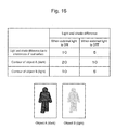
- Figures 13(a) and 13(b) are examples of objects, on parts of which light from the headlamp of the own vehicle is incident. (a) is a high obstacle and (b) is a low obstacle. In such a case, if edges are extracted without dividing images above and below the height of the headlamp illumination of the own vehicle, edges shown in Figures 13(c) and 13(d) are respectively obtained and cannot be distinguished.
- Figure 14 is a flowchart for explaining the operation method of the pre-crash safety system.
- the pre-crash safety system reads the obstacle information (the relative distance PYO[b], the lateral position PXO[b], and the lateral width WDO[b]) output by the recognition result output unit of any one of the obstacle detection devices explained above.
- the pre-crash safety system calculates collision predicted time TTC[i] of detected objects using Equation (4).
- Relative speed VYO[b] is calculated by subjecting the relative distance PYO[b] of the objects to pseudo-differential.
- TTC b PY b ⁇ VY b
- the pre-crash safety system calculates a risk DRECI[b] for obstacles.
- a method of estimating a predicted route is explained.
- a predicted route can be approximated by an arc having a turning radius R that passes the origin O.
- the turning radius R is represented by Equation (5) using a steering angle ⁇ , speed Vsp, a stability factor A, a wheel base L, and a steering gear ratio Gs of the own vehicle.
- the stability factor is an important factor serving as an index indicating the magnitude of a change that depends on speed of a steady turning circle of the vehicle.
- the turning radius R changes, with the stability factor A set as a coefficient, in proportion to a square of the speed Vsp of the own vehicle.
- the turning radius R can be represented by Equation (6) using the vehicle speed Vsp and a yaw rate y.
- the pre-crash safety system draws a perpendicular from the object X[b] to the center of the predicted route approximated by the arc having the turning radius R and calculates a distance L[b].
- the pre-crash safety system subtracts the distance L[b] from the vehicle width H. When a difference is a negative value, the pre-crash safety system sets the risk DRECI[b] to 0. When the difference is a positive value, the pre-crash safety system calculates the risk DRECI[b] according to Equation (7) below.
- DRECI b H - L b / H
- the pre-crash safety system is configured to perform, as the processing in steps 141 to 143, loop processing according to the number of detected objects.
- the pre-crash safety system selects, according to the risk DRECI[b] calculated in step 143, objects that satisfy the condition of Equation (8) and selects an object bMin having minimum collision predicted time TTC[b] among the selected objects.
- a predetermined value cDRECI# is a threshold for determining whether an object collides with the own vehicle.
- step 145 the pre-crash safety system determines, according to the collision predicted time TTC[bMin] of a selected object k, whether the own vehicle is in a range in which a brake is automatically controlled.
- the pre-crash safety system proceeds to step 146, executes the brake control, and ends the processing.
- the pre-crash safety system proceeds to step 147.
- step 147 the pre-crash safety system determines, according to the collision predicted time TTC[bMin] of the selected object bMin, whether the own vehicle is in a range in which an alarm is output. When Equation (10) holds, the pre-crash safety system proceeds to step 148, outputs an alarm, and ends the processing. When Equation (10) does not hold, the pre-crash safety system executes neither the brake control nor the alarm and ends the processing.
- TTC bMin ⁇ cTTCALM# As explained above, by using the vehicle-mounted object detection device 1000 or 2000 according to the present invention, in the scene shown in Figure 10 , even when light is incident only on the pedestrian's feet and it cannot be determined, only with the feet, whether the object is a pedestrian, edges in a region on which light is not incident can be extracted. Therefore, it is possible to recognize a pedestrian in front of the own vehicle and actuate the alarm and the brake control.
- a light and shade difference of a road surface caused by unevenness of the road surface in a state in which an external light that emits light of the same degree as the headlamp of the own vehicle is on is represented as DIF1_R.
- a light-colored object B having the same degree of light and shade difference when the external light is on is prepared.
- DIF1_B a light and shade difference on the inside and the outside of a contour of the object B in the ON state of the external light
- DIF1_B a light and shade difference on the inside and the outside of the contour of the object B in an OFF state of the external light
- An object A having completely the same shape as the object B but having a light and shade difference larger than that of the object B is prepared.
- a light and shade difference on the inside and the outside of a contour of the object A in the ON state of the external light is DIF1_A
- a light and shade difference on the inside and the outside of the contour of the object A in the OFF state of the external light is DIF0_A
- the edge threshold is changed according to an illumination state, irrespective of whether the external light is on or off, the object A is recognized and the object B is not recognized. Further, in the present invention, since an image region including an object is divided into small regions and the edge threshold is set according to illumination states of the small regions, even when the headlamps are emitting light when the external light is off, the object A is recognized and the object B is not recognized.
Landscapes
- Engineering & Computer Science (AREA)
- Physics & Mathematics (AREA)
- General Physics & Mathematics (AREA)
- Multimedia (AREA)
- Theoretical Computer Science (AREA)
- Remote Sensing (AREA)
- Radar, Positioning & Navigation (AREA)
- Computer Networks & Wireless Communication (AREA)
- Electromagnetism (AREA)
- Mechanical Engineering (AREA)
- Human Computer Interaction (AREA)
- Traffic Control Systems (AREA)
- Image Analysis (AREA)
- Radar Systems Or Details Thereof (AREA)
- Length Measuring Devices By Optical Means (AREA)
- Image Processing (AREA)
Abstract
Description
- The present invention relates to an obstacle detection device that detects an obstacle in front of an own vehicle.
- To reduce the number of casualties due to traffic accidents, the development of a preventive safety system that prevents accidents is underway. The preventive safety system is a system that operates under a situation in which accidents are highly likely to occur. For example, a pre-crash safety system or the like is put to practical use that calls the attention of a driver with an alarm when a collision with an obstacle in front of the driver's own vehicle is likely to occur and reduces damage to passengers with an automatic brake when a situation in which a collision is unavoidable occurs.
- In the system, as a method of detecting obstacles such as a vehicle or a pedestrian, there is a method of picking up an image of the front of the own vehicle with a camera and detecting an obstacle from the picked-up image. In this case, in order to make the detection less easily affected by colors of the obstacle and the background, the system uses a method of calculating an amount of change in a gray value from the picked-up image, generating an edge image obtained by extracting only portions where the amount of change is equal to or larger than a predetermined threshold, and calculating a degree of similarity between a contour of the obstacle on the edge image and templates of contours of obstacles stored in advance to thereby detect the obstacle.
- For example,
Patent Document 1 describes a method of detecting an object in front of an own vehicle with a laser radar, improving a contrast of a gray value of an image region including the object detected by the laser radar, and extracting an edge. With this method, even when an obstacle is present in a dark place such as the inside of a tunnel or the shade and a change in a gray value between the obstacle and the background is small, since a contrast of an image region including the object is improved, the change in the gray value increases and an edge can be extracted. - Patent Document 1: JP Patent Publication (Kokai) No. 2007-96510
- However, when a continuous contour of an obstacle is present across a bright section and a dark section, for example, when a headlamp of the own vehicle is on and light strikes a part of an obstacle such as a pedestrian or when the road surface is reflected and only the pedestrian's feet are lit up during backlight, even if a contrast is improved in an image region including the obstacle, a contrast of the dark section is not improved and an edge cannot be extracted. As a result, a contour present in the dark section among contours of the obstacle cannot be extracted and the obstacle is not recognized.
- When a threshold for an edge is tuned to make it possible to extract a contour in the dark section where a change in a gray value is small, the laser radar reacts to a slight change in the bright section and misdetections frequently occur. In particular, if this phenomenon occurs in a place where nothing is present in front of the own vehicle, an alarm or an automatic brake is actuated in the place and the safety of the own vehicle is spoiled.
- The present invention has been devised in view of the problems and it is an object of the present invention to provide an obstacle detection device that enables stable obstacle detection with less misdetections even when a bright section and a dark section are present in an obstacle and a continuous contour of the obstacle is present across the bright section and the dark section.
- In order to solve the problems, an obstacle detection device according to the present invention includes: an image acquiring unit that captures an image obtained by picking up an image of the outside of an own vehicle; a processed image generating unit that generates a processed image for detecting an obstacle from the captured image; a small region dividing unit that divides the processed image into plural small regions; an edge threshold setting unit that sets an edge threshold for each of the small regions from pixel values of the plural small regions and the processed image; an edge extracting unit that calculates a gray gradient value of each of the small regions from the plural small regions and the processed image and generates, using the edge threshold for the small region corresponding to the calculated gray gradient value, a binary edge image and a gradient direction image having information concerning the direction of an edge; an obstacle recognizing unit that sets a matching determination region for detecting an obstacle in the edge image and determines presence or absence of an obstacle from the edge image in the matching determination region and the gradient direction image corresponding to the edge image; and a recognition result output unit that outputs a result of the determination of presence or absence of an obstacle. The small region dividing unit is configured to divide the processed image into the plural small regions on the basis of an illumination state on the outside the own vehicle.
- An obstacle detection device according to the present invention includes: an image acquiring unit that captures an image obtained by picking up an image of the outside of an own vehicle; a processed region setting unit that sets a processed region for detecting an obstacle from the captured image; a small region dividing unit that divides the processed region into plural small regions; an edge threshold setting unit that sets an edge threshold for each of the small regions from pixel values of the plural small regions and the image captured by the image acquiring unit; an edge extracting unit that calculates a gray gradient value of each of the small regions from the plural small regions and the image captured by the image acquiring unit and generates, using the edge threshold for the small region corresponding to the calculated gray gradient value, a binary edge image and a gradient direction image having information concerning the direction of an edge; an obstacle recognizing unit that sets a matching determination region for detecting an obstacle in the edge image and determines presence or absence of an obstacle from the edge image in the matching determination region and the gradient direction image corresponding to the edge image; and a recognition result output unit that outputs a result of the determination of presence or absence of an obstacle. The small region dividing unit is configured to divide the processed region into the plural small regions on the basis of an illumination state on the outside the own vehicle.
- It is possible to provide an obstacle detection device that enables stable obstacle detection with less misdetections even when a bright section and a dark section are present in an obstacle and a continuous contour of the obstacle is present across the bright section and the dark section.
- This specification incorporates contents described in the specification and/or the drawings of Japanese Patent Application No.
2009-218405 -
- [
Figure 1] Figure 1 is a diagram showing a first embodiment of an obstacle detection device according to the present invention. - [
Figure 2] Figure 2 is a schematic diagram representing images and parameters used in the obstacle detection device according to the present invention. - [
Figure 3] Figure 3 is a diagram showing an example of processing in a processed image generating unit of the present invention. - [
Figure 4] Figure 4 is a diagram showing a division example of a small region dividing unit of the present invention. - [
Figure 5] Figure 5 is a diagram showing a flowchart of the small region dividing unit of the present invention. - [
Figure 6] Figure 6 is a diagram showing the weight of a Sobel filter used in an edge extracting unit of the present invention. - [
Figure 7] Figure 7 is a diagram showing an example of a local edge determiner in the obstacle recognizing unit of the present invention. - [
Figure 8] Figure 8 is a diagram showing an example of pedestrian determination using a discriminator in the obstacle recognizing unit of the present invention. - [
Figure 9] Figure 9 is a diagram showing a second embodiment of the obstacle detection device according to the present invention. - [
Figure 10] Figure 10 is a schematic diagram for explaining an obstacle recognition result of the present invention. - [
Figure 11] Figure 11 is a diagram showing a flowchart of another embodiment of the obstacle recognizing unit of the present invention. - [
Figure 12] Figure 12 is a diagram for explaining pair determination for edges in the obstacle recognizing unit of the present invention. - [
Figure 13] Figure 13 is a schematic diagram for explaining an obstacle recognition result of the present invention. - [
Figure 14] Figure 14 is a diagram showing an operation flowchart of a pre-crash safety system to which the obstacle detection device of the present invention is applied. - [
Figure 15] Figure 15 is a diagram showing a risk calculating method of the pre-crash safety system of the present invention. - [
Figure 16] Figure 16 is a diagram for explaining an example to which the obstacle detection device of the present invention is applied. -
- 71
- local edge determiner
- 81
- discriminator
- 711
- local edge frequency calculating unit
- 712
- threshold processing unit
- 812
- totaling unit
- 813
- threshold processing unit
- 1000, 2000
- vehicle-mounted object detection devices
- 1010
- camera
- 1011
- image acquiring unit
- 1021
- processed image generating unit
- 1031, 2031
- small region dividing units
- 1041, 2041
- edge threshold setting units
- 1051, 2051
- edge extracting units
- 1061, 2061
- obstacle recognizing units
- 1071
- recognition result output unit
- 1111
- object position detecting unit
- 1211
- own vehicle lighting detecting unit
- 1311
- road surface paint detecting unit
- 2021
- processed region setting unit
- 7111
- window
- 7112
- local edge frequency calculation region
- 7113
- angle condition
- 8101 to 8140
- local edge frequency determiners
- A first embodiment of an obstacle detection device according to the present invention is explained in detail below using the drawings.
Figure 1 is a block diagram of a vehicle-mountedobject detection device 1000 in the first embodiment. - The vehicle-mounted
object detection device 1000, which is an obstacle detection device, is incorporated in acamera 1010, which is an image pick-up device, mounted on an automobile, an integrated controller, or the like and used for detecting an obstacle such as a pedestrian set in advance from the inside of an image of the outside of an own vehicle picked up by thecamera 1010. In this embodiment, the vehicle-mountedobject detection device 1000 is configured to detect a pedestrian from the inside of an image obtained by picking up an image in front of the own vehicle. - The vehicle-mounted
object detection device 1000 includes a computer including a CPU, a memory, and an I/O. The vehicle-mountedobject detection device 1000 is programmed with predetermined processing and repeatedly executes the processing at a period set in advance. - The vehicle-mounted
object detection device 1000 includes, as shown inFigure 1 , animage acquiring unit 1011, a processedimage generating unit 1021, a smallregion dividing unit 1031, an edgethreshold setting unit 1041, anedge extracting unit 1051, anobstacle recognizing unit 1061, and a recognitionresult output unit 1071 and further includes, depending on an embodiment, an objectposition detecting unit 1111, an own vehiclelighting detecting unit 1211, and a road surfacepaint detecting unit 1311. - The
image acquiring unit 1011 captures an image obtained by photographing the outside of the own vehicle from thecamera 1010 attached to a position where thecamera 1010 can pick up an image of the outside of the own vehicle including the front of the own vehicle and writes the image on a RAM as an image IMGSRC[x][y]. The image IMGSRC[x][y] is a two-dimensional array and x and y respectively indicate coordinates of the image. - The processed
image generating unit 1021 generates a processed image IMGPROC[x][y] for detecting a pedestrian, who is an obstacle, from the inside of the image IMGSRC[x][y]. The processed image IMGPROC[x][y] is an image obtained by enlarging or reducing a part of the image IMGSRC[x][y] with a predetermined coefficient. Details of the processing are explained later. - The small
region dividing unit 1031 divides the processed image IMGPROC[x][y] into plural small regions (SXR[r], SYR[r], EXR[r], EYR[r]). Here, r represents an ID number of the small region. Although details of the division are explained later, the processed image is divided into plural small regions on the basis of an illumination state on the outside of the own vehicle. - The edge
threshold setting unit 1041 determines an edge threshold THR[r] for each of the small regions from pixel values of the processed image IMGPROC[x][y] in the small regions (SXR[r], SYR[r], EXR[r], EYR[r]). Details of setting of the threshold are explained later. - The
edge extracting unit 1051 calculates gray gradient values in the small regions of the processed image IMGPROC[x][y] and generates a binary edge image EDGE[x][y] and a gradient direction image DIRC[x][y] having information concerning the direction of an edge using the edge threshold THR[r] of a small region corresponding thereto. Details of the processing are explained later. - The
obstacle recognizing unit 1061 sets, in the edge image EDGE[x][y], matching determination regions (SXG[g], SYG[g], EXG[g], EYG[g]) for performing obstacle determination (e.g., pedestrian determination) and determines, using the edge image EDGE[x][y] in the matching determination regions and the gradient direction image DIRC[x][y] in a region of a position corresponding thereto. Here, g represents an ID number given when plural regions are set. Details of the recognition processing are explained later. - The recognition
result output unit 1071 performs, on the basis of a determination result of theobstacle recognizing unit 1061, output for changing a function of a vehicle according to obstacle information including at least a relative distance PYO[b] between an obstacle such as a recognized pedestrian and the vehicle. For example, the recognitionresult output unit 1071 outputs a position (the relative distance PYO[b], a lateral position PXO[b], and lateral width WDO[b]) of the recognized pedestrian. Here, b represents an ID number given when plural objects are detected. These outputs may be directly output from the vehicle-mountedobject detection device 1000 or communication using a LAN (Local Area Network) may be performed. - The object
position detecting unit 1111 acquires a detection signal from a radar, which is an obstacle detecting unit that detects an object around the own vehicle, such as a millimeter wave radar or a laser radar mounted on the own vehicle and detects the position of an obstacle present in front of the own vehicle. For example, as shown inFigure 3 , the objectposition detecting unit 1111 acquires a position (a relative distance PY[b], a lateral position PX[b], and lateral width WD[b]) of an obstacle such as apedestrian 32 around the vehicle from the radar. Here, b represents an ID number given when plural objects are detected. Position information of these objects may be acquired by directly inputting a signal of the radar to the vehicle-mountedobject detection device 1000 or may be acquired by performing communication using the radar and the LAN (Local Area Network). The object position detected by the objectposition detecting unit 1111 is used by the processedimage generating unit 1021 and the smallregion dividing unit 1031. - The own vehicle
lighting detecting unit 1211 determines whether the own vehicle has its lamps on and, if the own vehicle has its lamps on, outputs "1" and, otherwise, outputs "0". As the lighting determination, whether the lamps are on may be determined by directly inputting a signal of a light switch or a signal of the light switch may be acquired by performing communication using the LAN (Local Area Network) to determine whether the lamps are on. Whether the lamps are on may be determined using light and shade of an image acquired by theimage acquiring unit 1011. For example, when the lamps are on, the inside of a lighted range appears bright and the outside of the range appears dark. Therefore, for example, it is possible to calculate, using a camera image and a camera geometric model, a light illuminated range on the road surface on an image and determine whether the lamps are on according to whether a difference between an average luminance value in the light illuminated range and an average luminance value outside the light illuminated range is equal to or larger than a fixed threshold. An output of the own vehiclelighting detecting unit 1211 is used by the smallregion dividing unit 1031. - The road surface
paint detecting unit 1311 detects a road surface paint on a pedestrian crossing or the like present in front of the own vehicle. For the detection of the road surface paint, there is a method of acquiring information concerning navigation through communication using the LAN (Local Area Network), acquiring, for example, information concerning a crossing with a traffic light, and acquiring a distance from the own vehicle to the pedestrian crossing. The road surfacepaint detecting unit 1311 may determine the road paint using light and shade of an image acquired by theimage acquiring unit 1011. For example, since the road paint on the pedestrian crossing or the like is white, an image of the road surface paint is picked up bright on the image. Therefore, the road surface paint can be detected by means explained below. First, the road surfacepaint detecting unit 1311 calculates, using a camera image and a camera geometric model, a road surface region of the image on the image and extracts pixels in which luminance values of the road surface region is equal to or larger than a threshold TH_GBright. Subsequently, the road surfacepaint detecting unit 1311 groups the extracted pixels into groups of the pixels adjacent to one another and acquires, from a region where an area is a threshold TH_GArea among the grouped regions, a y coordinate Y_Gmin at the upper end on the image of a region present at the highest position on the image. Further, the road surfacepaint detecting unit 1311 calculates a distance from the own vehicle to the position of Y_Gmin using a camera geometry. According to the processing explained above, it is possible to calculate a distance from the own vehicle to the road surface paint. An output of the road surfacepaint detecting unit 1311 is used by the smallregion dividing unit 1031. -
Figure 2 is a diagram showing, using an example, the images and the regions used in the above explanation. As shown in the figure, the processed image IMGPROC[x][y] is generated from the image IMGSRC[x][y]. The edge image EDGE[x][y] and the gradient direction image DIRC[x][y] are generated from the processed image IMGPROC[x][y]. The small regions (SXR[r], SYR[r], EXR[r], EYR[r]) are set to divide the processed image IMGPROC[x][y]. The matching determination regions (SXG[g], SYG[g], EXG[g], EYG[g]) are regions having a determined size in the edge image EDGE[x][y] and the gradient direction image DIRC[x][y]. - Next, content of the processing in the processed
image generating unit 1021 is explained usingFigure 3. Figure 3 shows an example of the processing by the processed image generating unit. - The processed
image generating unit 1021 selects a region where pedestrian detection processing is performed in the image IMGSRC[x][y], calculates a range of coordinates of the region, a start point SXP and an end point EXP on an x coordinate (the lateral direction) and a start point SYP and an end point EYP on a y coordinate (the longitudinal direction), and generates the processed image IMGPROC[x][y] from the region. - The processed
image generating unit 1021 may use or may not use the objectposition detecting unit 1111. First, processing performed when the objectposition detecting unit 1111 is used in the processedimage generating unit 1021 is explained.Figure 3(a) is an example of the processing by the processed image generating unit performed when the objectposition detecting unit 1111 is used. - The processed
image generating unit 1021 calculates, from the relative distance PY[b], the lateral position PX[b], and the lateral width WD[b] of an obstacle detected by the objectposition detecting unit 1111, a position on an image of the detected obstacle (a start point SXB and an end point EXB on the x coordinate (the lateral direction) and a start point SYB and an end point EYB on the y coordinate (the longitudinal direction)). If camera geometric parameters that associate coordinates on a camera image and a positional relation in the real world are calculated in advance by a method such as camera calibration and the height of an object is assumed as, for example, 180 [cm] in advance, a position on the image is uniquely determined. - In some cases, a difference between a position on an image of an object detected by the object
position detecting unit 1111 and a position on an image of the same object appearing in a camera image occurs because of reasons such as an error of attachment of thecamera 1010 and a delay in communication with a radar. Therefore, an object position (SXP, EXP, SYP, EYP) obtained by correcting an object position (SXB, EXB, SYB, EYB) on the image is calculated. The correction expands a region by a predetermined amount or moves the region. For example, SXB, EXB, SYB, and EYB are expanded up and down and to the left and right by a predetermined number of pixels. - Further, the processed
image generating unit 1021 slices out the image IMGSRC[x][y] surrounded by the corrected object position (SXP, EXP, SYP, EYP) and enlarges or reduces the size of the object in the image to a predetermined size to thereby generate the processed image IMGPROC[x][y]. In this embodiment, the processedimage generating unit 1021 enlarges or reduces the image using the camera geometry such that all objects having height of 180 [cm] and width of 60 [cm] have a size of 16 dots x 12 dots in the processed image IMGPROC[x][y]. - In other words, when the object
position detecting unit 1111 is used, the processedimage generating unit 1021 generates the processed image IMGPROC[x][y] on the basis of the image IMGSRC[x][y] acquired from theimage acquiring unit 1011 and the position of the obstacle detected by the objectposition detecting unit 1111. - When the processing is applied to plural regions, the processed
image generating unit 1021 generates processed images IMGPROC[x][y] of the regions and separately carries out, for the respective processed images, processing by a division boundary setting unit to processing by an obstacle recognizing unit explained below. - Next, processing for generating the processed image IMGPROC[x][y] without using the object
position detecting unit 1111 in the processedimage generating unit 1021 is explained. - As a method of selecting a region when the object
position detecting unit 1111 is not used, for example, there are a method of setting a region to search through an entire image while changing the size of a region and a method of setting a region while limiting the region to a specific position and a specific size. When the region is limited to the specific position, there is a method of limiting, using, for example, own vehicle speed, the region to a position to where the own vehicle advances after T seconds. -
Figure 3(b) is an example of a search for a position to where the own vehicle advances after 2.3 seconds. As the position and the size of a processed region, the processedimage generating unit 1021 calculates a range (SYP2, EYP2) in the y direction on the image IMGSRC[x][y] using the camera geometric parameters from road surface height (0 cm) at a relative distance to the position to where the own vehicle advances after 2.3 seconds and assumed height of a pedestrian (in this embodiment, 180 cm). A range (SXP2, EXP2) in the x direction may not be limited or may be limited according to, for example, a predicted route of the own vehicle. - Further, the processed
image generating unit 1021 slices out the image IMGSRC[x][y] surrounded by the corrected object position (SXP, EXP, SYP, EYP) and enlarges or reduces the size of the object in the image to a predetermined size to thereby generate the processed image IMGPROC[x][y]. In this embodiment, the processedimage generating unit 1021 enlarges or reduces the image using the camera geometry such that all objects having height of 180 [cm] and width of 60 [cm] have a size of 16 dots x 12 dots in the processed image IMGPROC[x][y]. - Next, content of the processing in the small
region dividing unit 1031 is explained usingFigures 4 and5 .Figure 4 is a division example of the smallregion dividing unit 1031.Figure 5 is a flowchart in this embodiment of the smallregion dividing unit 1031. - In this embodiment, as a system for division into small regions, three kinds of dividing methods are explained: a system using the object
position detecting unit 1111 and the own vehiclelighting detecting unit 1211, a system using the road surfacepaint detecting unit 1311, and a system not using any of the objectposition detecting unit 1111, the own vehiclelighting detecting unit 1211, and the road surfacepaint detecting unit 1311. Next, a method of selecting the three systems according to an illumination state on the outside of the vehicle is explained. - First, a first division system not using any of the object
position detecting unit 1111, the own vehiclelighting detecting unit 1211, and the road surfacepaint detecting unit 1311 is explained. In this case, the smallregion dividing unit 1031 divides the processed image IMGPROC[x][y] into upper and lower regions with a y coordinate VPY at a vanishing point of an image as a boundary: a small region 1 (SXR[0], SYR[0], EXR[0], EYR[0]=VPY) and a small region 2 (SXR[1], SYR[1]=VPY, EXR[1], EYR[1]). Thesmall region 1 and thesmall region 2 may be set without a gap as shown inFigure 4(a) . As shown inFigure 4(b) , for example, hysteresis of about five pixels may be provided with division height VPY on the image as a boundary to prevent an edge due to a difference in an illumination state from occurring. In the case of an example shown inFigure 4(b) , all edges in the portion of the hysteresis are set to zero. - Next, a second division system using the object
position detecting unit 1111 and the own vehiclelighting detecting unit 1211 is explained. As shown inFigure 4(c) , when an image including an obstacle detected by the objectposition detecting unit 1111 is generated by the processedimage generating unit 1021 and it is determined by the own vehiclelighting detecting unit 1211 that the own vehicle is emitting light, the smallregion dividing unit 1031 calculates light illumination height LZ for an object according to Equation (1) below from the relative distance PY[b] of the obstacle detected by the objectposition detecting unit 1111, an illumination angle LANGL of the light of the own vehicle, and light height LHEIGHT of the own vehicle. -

- The small
region dividing unit 1031 converts LZ into a coordinate LZY on the image using the camera geometry and divides the processed image IMGPROC[x][y] into a small region 1 (SXR[0], SYR[0], EXR[0], EYR[0]=LZY) and a small region 2 (SXR[1], SYR[1]=LZY, EXR[1], EYR[1]) with LZY as a boundary. Thesmall region 1 and thesmall region 2 may be set without a gap as shown inFigure 4(a) . As shown inFigure 4(b) , for example, hysteresis of about five pixels may be provided with division height LZY on the image as a boundary to prevent an edge due to light from occurring. In the case of the example shown inFigure 4(b) , all edges in the portion of the hysteresis are set to zero. - Further, a third division system using the road surface
paint detecting unit 1311 is explained. In this case, the smallregion dividing unit 1031 divides the processed image IMGPROC[x][y] into upper and lower images with the position of detected road surface paint as a boundary. When a distance to the road surface paint is represented as PZ, the smallregion dividing unit 1031 converts, using a camera geometry model, the distance PZ into a y coordinate position PZY of the road surface paint on the image and divides, with PZY as a boundary, the processed image IMGPROC[x][y] into a small region 1 (SXR[0], SYR[0], EXR[0], EYR[0]=PZY) and a small region 2 (SXR[1], SYR[1]=PZY, EXR[1], EYR[1]). Thesmall region 1 and thesmall region 2 may be set without a gap as shown inFigure 4(a) . As shown inFigure 4(b) , for example, hysteresis of about five pixels may be provided with division height PZY on the image as a boundary to prevent an edge due to a difference in an illumination state from occurring. In the case of the example shown inFigure 4(b) , all edges in the portion of the hysteresis are set to zero. - Next, a method of selecting the three division systems according to an illumination state on the outside of the vehicle is explained using
Figure 5. Figure 5 is a flowchart describing switching conditions for the three division systems. - First, in
step 51, the smallregion dividing unit 1031 determines, using an output of the own vehiclelighting detecting unit 1211, whether the own vehicle has its lamps on. When it is determined that the own vehicle has its lamps on, the smallregion dividing unit 1031 selects the second dividing means. When the own vehicle does not have its lamps on, the smallregion dividing unit 1031 shifts to the next step. - Subsequently, at
step 52, the smallregion dividing unit 1031 determines, using an output of the road surfacepaint detecting unit 1311, whether road surface paint is present in front of the own vehicle. When it is determined that road surface paint is present in front of the own vehicle, the smallregion dividing unit 1031 selects the third dividing means. When it is determined that road surface paint is absent, the smallregion dividing unit 1031 selects the first dividing means. - As explained above, when it is determined by the own vehicle
lighting detecting unit 1211 that the headlamp of the own vehicle is emitting light, the smallregion dividing unit 1031 determines that a part of a pedestrian is lit up by the headlamp of the own vehicle, selects the second dividing means, and can divide a processed image into a region where the headlamps are emitting light and a dark region. When road surface paint is detected in front of the own vehicle by the road surfacepaint detecting unit 1311, the smallregion dividing unit 1031 determines that the lower half body of a pedestrian standing on the road surface paint appears bright, selects the third dividing means, and can divide a processed image into a bright region including the road surface paint and a region without the road surface paint. Further, when the headlamp of the own vehicle is not on and road surface paint is not detected, the smallregion dividing unit 1031 selects the first dividing means. Even when the road surface is reflected by backlight and appears bright, the first dividing means can divide the processed image into a region bright with backlight and a region where the road surface does not appear. - In this embodiment, as the three dividing means, the road surface
paint detecting unit 1311 only has to include at least the first dividing means and does not need to include all the three dividing means. When the road surfacepaint detecting unit 1311 does not include any one of the dividing means, the conditional branch shown inFigure 5 follows the route of NO. - Next, content of the processing by the edge
threshold setting unit 1041 is explained.
The edgethreshold setting unit 1041 determines the edge threshold THR[r] according to an average AVE[r] and a variance VAR[r] of gray values in the small regions SXR[r], SYR[r], EXR[r], and EYR[r] of the processed image IMGPROC[x][y]. Here, r is an ID number of the small region. - The edge threshold is determined by, for example, a method of using a table having the average AVE[r] of gray values as an argument or a method of using a two-dimensional map having the average AVE[r] and the variance [r] of gray values as arguments.
- In the method of using the map having the average AVE[r] and the variance VAR[r] as arguments, a threshold of an optimum edge in images having various kinds of brightness is manually determined in advance and averages and variances at that point formed as a map are used. Consequently, it is possible to determine an optimum threshold from the average AVE[r] and the variance VAR[r] of gray values in the small regions.
- For determination of the edge threshold THR[r], an average and a variance of pixel values of an image obtained as a result of applying, for example, a Sobel filter for the processed image IMGPROC[x][y] may be used rather than gray values. An arithmetic operation of the Soble filter is explained later.
- Next, content of the processing by the
edge extracting unit 1051 is explained.
Theedge extracting unit 1051 applies a differential filter such as a Sobel filter to the processed image IMGPROC[x][y] to calculate the intensity and the direction of the gradient of an image and subjects the intensity of the gradient to threshold processing to thereby extract an edge. In the following explanation, the Sobel filter is applied as the differential filter. - The Sobel filter has a size of 3x3 as shown in
Figure 6 . Two kinds of filters are present: anx direction filter 61 that calculates a gradient in the x direction and a y direction filter 62 that calculates a gradient in the y direction. In calculating a gradient in the x direction from the processed image IMGPROC[x][y], theedge extracting unit 1051 performs, for each pixel of the processed image IMGPROC[x][y], a product-sum operation of pixel values of nine pixels in total including the pixel and eight pixels around the pixel and weight of thex direction filter 61 in a position corresponding to the pixel. A result of the product-sum operation is a gradient in the x direction in the pixel. Calculation of a gradient in the y direction is the same. When a calculation result of a gradient in the x direction in a certain position (x, y) of the processed image IMGPROC[x][y] is represented as dx and a calculation result of a gradient in the y direction is represented as dy, a gradient intensity image DMAG[x][y] and a gradient direction image DIRC[x][y] are calculated by Equations (2) and (3) below. -


- The
edge extracting unit 1051 calculates, concerning all pixels in the small regions SXR[r], SYR[r], EXR[r], and EYR[r] in the processed image IMGPROC[x][y], the gradient intensity image DMAG[x][y] and the gradient direction image DIRC[x][y]. Subsequently, theedge extracting unit 1051 compares the edge threshold THR[r] and DMAG[x][y] according to the small regions SXR[r], SYR[r], EXR[r], and EYR[r] to which the calculated DMAG[x][y] belongs. If DMAG[x][y] > THR[r], theedge extracting unit 1051stores 1 in the edge image EDGE[x][y]. Otherwise, theedge extracting unit 1051stores 0 in the edge image EDGE[x][y]. The edge image EDGE[x][y] is a two-dimensional array having the same size as the image IMGSRC[x][y]. The coordinate x, y of EDGE[x][y] corresponds to the coordinate of IMGSRC[x][y]. - As explained above, the small
region dividing unit 1031 divides the processed image IMGPROC[x][y] including the object into the small regions (SXR[r], SYR[r], EXR[r], and EYR[r]) according to an illumination state on the outside of the vehicle. The edgethreshold setting unit 1041 sets the edge threshold THR[r] for each of the small regions and extracts an edge using the edge threshold THR[r] for each of the small regions. Consequently, even in a scene in which a part of a pedestrian appears bright, it is possible to correctly extract edges of a contour of the pedestrian in a bright region and a dark region. - Next, content of the processing by the
obstacle recognizing unit 1061 is explained with reference to detection of a pedestrian as an example. - First, the
obstacle recognizing unit 1061 sets the matching determination regions (SXG[g], SYG[g], EXG[g], EYG[g]) for performing pedestrian determination in the edge image EDGE[x][y]. As explained concerning the processedimage generating unit 1021, in this embodiment, an image is enlarged or reduced using the camera geometry such that all objects having height of 180 [cm] and width of 60 [cm] have a size of 16 dots x 12 dots in the processed image IMGPROC[x][y]. Therefore, when the size of a matching determination region is set as 16 dots x 12 dots and the edge image EDGE[x][y] is larger than 16 dots x 12 dots, theobstacle recognizing unit 1061 sets plural matching determination regions to be laid at a fixed interval in the edge image EDGE[x][y]. Concerning each of the matching determination regions (SXG[g], SYG[g], EXG[g], EYG[g]), theobstacle recognizing unit 1061 performs determination using adiscriminator 81 explained in detail below and, if there is a place where an output of thediscriminator 81 is 1, determines that a pedestrian is present in the position. - Next, a method of determining whether an obstacle is a pedestrian using the
discriminator 81 is explained.
Examples of a method of detecting a pedestrian through image processing include a method by template matching for preparing plural representative templates of pedestrian patterns and performing a differential cumulative operation or a normalization correlation operation to calculate a degree of coincidence and a method of performing pattern recognition using a discriminator such as a neural network. Irrespective of which of the methods is adopted, a database of sources serving as indexes for determining whether an obstacle is a pedestrian in advance is necessary. Patterns of various pedestrians are stored as a database and a representative template is created and a discriminator is generated from the database. In an actual environment, pedestrians in various clothes, postures, and body shapes are present and conditions such as illumination and weather are different. Therefore, it is necessary to prepare a large number of databases and reduce misdeterminations. In detecting a pedestrian, the former method by the template matching is not realistic because the number of templates is enormous if determination omission is prevented. - Therefore, in this embodiment, the latter method of determining a pattern using the discriminator is adopted. The size of the discriminator does not depend on the size of a database of sources. A database for generating the discriminator is referred to as teacher data.
- The
discriminator 81 used in this embodiment determines whether an obstacle is a pedestrian on the basis of plural local edge determiners. First, the local edge determiner is explained using an example shown inFigure 7 . Alocal edge determiner 71 is a determiner that receives input of the edge image EDGE[x][y], the gradient direction image DIRC[x][y], and the matching determination regions (SXG[g], SYG[g], EXG[g], EYG[g]) and outputs abinary value local edge determiner 71 includes a local edgefrequency calculating unit 711 and athreshold processing unit 712. - The local edge
frequency calculating unit 711 has a local edgefrequency calculation region 7112 in awindow 7111 having the same size as the matching determination region (SXG[g], SYG[g], EXG[g], EYG[g]). The local edgefrequency calculating unit 711 sets, from a positional relation between the matching determination region (SXG[g], SYG[g], EXG[g], EYG[g]) and thewindow 7111, positions where a local edge frequency is calculated in the edge image EDGE[x][y] and the gradient direction image DIRC[x][y] and calculates a local edge frequency MWC. The local edge frequency MWC is a total number of pixels in which an angle value of the gradient direction image DIRC[x][y] satisfies anangle condition 7113 and the edge image EDGE[x][y] in a position corresponding thereto is 1. - In the case of the example shown in
Figure 6 , theangle condition 7113 is a condition that the angle value is between 67.5 degrees to 112.5 degrees or between 267.5 degrees and 292.5 degrees and is a condition for determining whether a value of the gradient direction image DIRC[x][y] is in a fixed range. - The
threshold processing unit 712 has a threshold THWC set in advance. If the local edge frequency MWC calculated by the local edgefrequency calculating unit 711 is equal to or higher than the threshold THWC, thethreshold processing unit 712 outputs 1. Otherwise, thethreshold processing unit 712 outputs 0. If the local edge frequency MWC calculated by the local edgefrequency calculating unit 711 is equal to or lower than the threshold THWC, thethreshold processing unit 712 mayoutput 1. Otherwise, thethreshold processing unit 712 mayoutput 0. - Next, the discriminator is explained using
Figure 8 . Thediscriminator 81 receives input of the edge image EDGE[x][y], the gradient direction image DIRC[x][y], and the matching determination regions (SXG[g], SYG[g], EXG[g], EYG[g]). If a pedestrian is present in the regions, thediscriminator 81outputs 1. If a pedestrian is absent in the regions, thediscriminator 81outputs 0. Thediscriminator 81 includes forty localedge frequency determiners 8101 to 8140, a totalingunit 812, and athreshold processing unit 813. - Each kind of processing by the local
edge frequency determiners 8101 to 8140 is the same as the processing by thelocal edge determiner 71. However, the local edgefrequency calculation region 7112, theangle condition 7113, and the threshold THWC are respectively different from those of thelocal edge determiner 71. - The totaling
unit 812 multiplies outputs from the localedge frequency determiners 8101 to 8140 with weights WWC1 to WWC40 corresponding thereto and outputs a total of the outputs multiplied with the weights WWC1 to WWC40. - The
threshold processing unit 813 has a threshold THSC. If an output of the totalingunit 812 is larger than the threshold THSC, thethreshold processing unit 813 outputs 1. Otherwise, thethreshold processing unit 813 outputs 0. - The local edge
frequency calculation region 7112, theangle condition 7113, the threshold THWC, the weights WWC1 to WWC40, and the final threshold THSC, which are parameters of the local edge frequency determiners of thediscriminator 81, are adjusted using the teacher data such that 1 is output when an input image to the discriminator is a pedestrian and 0 is output when the input image is not a pedestrian. Means for machine learning such as AdaBoost may be used for the adjustment or the adjustment may be performed manually. - For example, a procedure for determining parameters using AdaBoost from NPD pieces of teacher data of pedestrians and NBG pieces of teacher data of non-pedestrians is as explained below. In the following explanation, the local edge frequency determiner is represented as cWC[m]. Here, m is an ID number of the local edge frequency determiner.
- First, plural (e.g., one million) local edge frequency determiners cWC[m] having different local edge
frequency calculation regions 7112 andangle conditions 7113 are prepared. Each of the local edge frequency determiners cWC[m] calculates values of the local edge frequency MWC from all teacher data and determines the threshold THWC for each of the values. As the threshold THWC, a value that can best classify teacher data of pedestrians and teacher data of non-pedestrians is selected. - Next, the
discriminator 81 gives weight of wPD[nPD]=1/2NPD to each of the teacher data of the pedestrians. Similarly, thediscriminator 81 gives weight of wBG[nBG]=1/2NBG to each of the teacher data of the non-pedestrians. Here, nPD is an ID number of the teacher data of the pedestrians and nBG is an ID number of the teacher data of the non-pedestrians. - With k set to 1, thereafter, the
discriminator 81 repeatedly performs processing.
First, thediscriminator 81 normalizes weight such that a total of the weights of the teacher data of all the pedestrians and non-pedestrians is 1. Subsequently, thediscriminator 81 calculates error detection ratios cER[m] of the local edge frequency determiners. The error detection ratio cER[m] is, in the local edge frequency determiner cWC[m], a total of weights of the teacher data of the pedestrians, outputs of which are 0 when the teacher data of the pedestrians is input to the local edge frequency determiner cWC[m], or the teacher data of the non-pedestrians, outputs of which are 1 when the teacher data of the non-pedestrians is input to the local edge frequency determiner cWC[m], i.e., teacher data, outputs of which are wrong. - After calculating the error detection ratios cER[m] of all the local edge frequency determiners, the
discriminator 81 selects ID mMin of the local edge frequency determiner having a minimum error detection ratio and sets a final local edge frequency determiner WC[k] equal to cWC[mMin]. - Subsequently, the
discriminator 81 updates the weights of the teacher data. For the update, thediscriminator 81 multiplies the weights of the teacher data of the pedestrians, results of which obtained by applying the final local edge frequency determiner WC[k] are 1, among the teacher data of the pedestrians and the teacher data of the non-pedestrians, results of which obtained by applying the final local edge frequency determiner WC[k] are 0, among the teacher data of the non-pedestrians, i.e., the weights of the teacher data having correct outputs with a coefficient BT[k]=cER[mMin]/(1-cER[mMin]). - With k set to k+1, the
discriminator 81 repeats the processing until k reaches a value set in advance (e.g., 40). The final local edge frequency determiner WC obtained after the end of the repeated processing is thediscriminator 81 automatically adjusted by AdaBoost. The weights WWC1 to WWC40 are calculated from 1/BT[k] and the threshold THSC is set to 0.5. - As explained above, the
obstacle recognizing unit 1061 can detect a pedestrian using edges of a contour of the pedestrian extracted by theedge extracting unit 1051. - The
discriminator 81 used for detection of a pedestrian is not limited to the method explained in this embodiment. Template matching using normalized correlation, a neural network discriminator, a support vector machine discriminator, a Bayes discriminator, and the like may be used. - The dividing means of the small
region dividing unit 1031 are not limited to the three dividing means in this embodiment and may be two or less or four or more dividing means. - Next, a second embodiment of a vehicle-mounted
object detection device 2000, which is the obstacle detection device according to the present invention, is explained below using the drawings. -
Figure 9 is a block diagram representing the embodiment of the vehicle-mountedobject detection device 2000. In the following explanation, only components different from those of the vehicle-mountedobject detection device 1000 explained above are explained in detail. The same components are denoted by the same reference numerals and signs and explanation of the components is omitted. - The vehicle-mounted
object detection device 2000 is incorporated in a camera mounted on an automobile, an integrated controller, or the like and used for detecting an obstacle from the inside of an image picked up by the camera. In this embodiment, the vehicle-mountedobject detection device 2000 is configured to detect a pedestrian from the inside of an image obtained by picking up an image around an own vehicle. - The vehicle-mounted
object detection device 2000 includes a computer including a CPU, a memory, and an I/O. The vehicle-mountedobject detection device 2000 is programmed with predetermined processing and repeatedly executes processing at a period set in advance. The vehicle-mountedobject detection device 2000 includes, as shown inFigure 9 , theimage acquiring unit 1011, a processedregion setting unit 2021, a smallregion dividing unit 2031, an edgethreshold setting unit 2041, anedge extracting unit 2051, anobstacle recognizing unit 2061, and the recognitionresult output unit 1071 and further includes, depending on an embodiment, the objectposition detecting unit 1111, the own vehiclelighting detecting unit 1211, and the road surfacepaint detecting unit 1311. - The processed
region setting unit 2021 sets a processed region (SXP, SYP, EXP, EYP) where a pedestrian, who is an obstacle, is detected from the inside of the image IMGSRC[x][y]. Details of the setting are explained later. - The small
region dividing unit 2031 divides the processed region (SXP, SYP, EXP, EYP) of the image IMGSRC[x][y] into plural small regions (SXR[r], SYR[r], EXR[r], EYR[r]). Here, r is an ID number of the small region. Although details of the division are explained later, the processed image is divided into plural small regions on the basis of an illumination state on the outside of the own vehicle. - The edge
threshold setting unit 2041 determines the edge threshold THR[r] from pixel values of the image IMGSRC[x][y] in the small regions (SXR[r], SYR[r], EXR[r], EYR[r]). Details of setting of the threshold are explained later. - The
edge extracting unit 2051 calculates gray gradient values in the small regions of the image IMGSRC[x][y] and generates, using the edge threshold THR[r] of a small region corresponding thereto, the binary edge image EDGE[x][y] and the gradient direction image DIRC[x][y] having information concerning the direction of an edge. Details of the processing are explained later. - The
obstacle recognizing unit 2061 sets, in the edge image EDGE[x][y], the matching determination regions (SXG[g], SYG[g], EXG[g], EYG[g]) for performing pedestrian determination and determines presence or absence of a pedestrian using the edge image EDGE[x][y] in the matching determination regions and the gradient direction image DIRC[x][y] in a region of a position corresponding thereto. Here, g represents an ID number given when plural regions are set. Details of the recognition processing are explained later. - Next, content of the processing in the processed
region setting unit 2021 is explained usingFigure 3 .
The processedregion setting unit 2021 selects a region where pedestrian detection processing is performed in the image IMGSRC[x][y] and calculates a range of coordinates of the region, the start point SXP and the end point EXP on the x coordinate (the lateral direction) and the start point SYP and the end point EYP on the y coordinate (the longitudinal direction). - The processed
region setting unit 2021 may use or may not use the objectposition detecting unit 1111. First, processing performed when the objectposition detecting unit 1111 is used in the processedregion setting unit 2021 is explained. - The processed
region setting unit 2021 calculates, from the relative distance PY[b], the lateral position PX[b], and the lateral width WD[b] of an object detected by the objectposition detecting unit 1111, a position on an image of the detected object (the start point SXB and the end point EXB on the x coordinate (the lateral direction) and the start point SYB and the end point EYB on the y coordinate (the longitudinal direction)). If camera geometric parameters that associate coordinates on a camera image and a positional relation in the real world are calculated in advance by a method such as camera calibration and the height of an object is assumed as, for example, 180 [cm] in advance, a position on the image is uniquely determined. - In some case, a difference between a position on an image of an object detected by the object
position detecting unit 1111 and a position on an image of the same object appearing in a camera image occurs because of reasons such as an error of attachment of thecamera 1010 and a delay in communication with a radar. Therefore, the object position (SXP, EXP, SYP, EYP) obtained by correcting the object position (SXB, EXB, SYB, EYB) on the image is calculated. The correction expands a region by a predetermined amount or moves the region. For example, SXB, EXB, SYB, and EYB are expanded up and down and to the left and right by a predetermined number of pixels. An object position obtained as a result of this correction is set as the processed region (SXP, EXP, SYP, EYP). - When the processing is performed for plural regions, the processed region (SXP, EXP, SYP, EYP) is set for each of the regions. The processing by the small region dividing unit to the processing by the obstacle recognizing unit are individually carried out on respective processed images.
- Next, processing for setting the processed region (SXP, EXP, SYP, EYP) without using the object
position detecting unit 1111 in the processedregion setting unit 2021 is explained. - As a method of selecting a region when the object
position detecting unit 1111 is not used, for example, there are a method of setting a region to search through an entire image while changing the size of a region and a method of setting a region while limiting the region to a specific position and a specific size. When the region is limited to the specific position, there is a method of limiting, using, for example, own vehicle speed, the region to a position to where the own vehicle advances after T seconds. -
Figure 3(b) is an example of searching for, using own vehicle speed, a position to where the own vehicle advances after 2.3 seconds. As the position and the size of a processed region, the processedregion setting unit 2021 calculates the range (SYP2, EYP2) in the y direction on the image IMGSRC[x][y] using the camera geometric parameters from road surface height (0 cm) at a relative distance to the position to where the own vehicle advances after 2.3 seconds and assumed height of a pedestrian (in this embodiment, 180 cm). The range (SXP2, EXP2) in the x direction may not be limited or may be limited according to, for example, a predicted route of the own vehicle. A region (SXP2, SYP2, EXP2, EYP2) obtained as a result of this processing is set as the processed region (SXP, EXP, SYP, EYP). - Next, content of the processing in the small
region dividing unit 2031 is explained usingFigures 4 and5 . - In this embodiment, as a system for division into small regions, three kinds of dividing methods are explained: a system using the object
position detecting unit 1111 and the own vehiclelighting detecting unit 1211, a system using the road surfacepaint detecting unit 1311, and a system not using all of the objectposition detecting unit 1111, the own vehiclelighting detecting unit 1211, and the road surfacepaint detecting unit 1311. Next, a method of selecting the three systems according to an illumination state on the outside of the vehicle is explained. - First, a first division system not using all of the object
position detecting unit 1111, the own vehiclelighting detecting unit 1211, and the road surfacepaint detecting unit 1311 is explained. In this case, the smallregion dividing unit 2031 divides the processed region (SXP, EXP, SYP, EYP) in the image IMGSRC[x][y] into upper and lower regions with the y coordinate VPY at a vanishing point of an image as a boundary: the small region 1 (SXR[0], SYR[0], EXR[0], EYR[0]=VPY) and the small region 2 (SXR[1], SYR[1]=VPY, EXR[1], EYR[1]). Thesmall region 1 and thesmall region 2 may be set without a gap as shown inFigure 4(a) . As shown inFigure 4(b) , for example, hysteresis of about five pixels may be provided with the division height VPY on the image as a boundary to prevent an edge due to a difference in an illumination state from occurring. In the case of the example shown inFigure 4(b) , all edges in the portion of the hysteresis are set to zero. - Next, a second division system using the object
position detecting unit 1111 and the own vehiclelighting detecting unit 1211 is explained. As shown inFigure 4(c) , when an image including an object detected by the objectposition detecting unit 1111 is set by the processedregion setting unit 2021 and it is determined by the own vehiclelighting detecting unit 1211 that the own vehicle is emitting light, the smallregion dividing unit 2031 calculates the light illumination height LZ for an object according to Equation (1) above from the relative distance PY[b] of the object detected by the objectposition detecting unit 1111, the illumination angle LANGL of the light of the own vehicle, and light height LHEIGHT of the own vehicle. The illumination angle LANGL of the light of the own vehicle and the light height LHEIGHT of the own vehicle are values set in advance according to a type of a vehicle. - The small
region dividing unit 2031 converts LZ into a coordinate LZY on the image using the camera geometry and divides the processed region (SXP, EXP, SYP, EYP) in the image IMGSRC[x][y] into the small region 1 (SXR[0], SYR[0], EXR[0], EYR[0]=LZY) and the small region 2 (SXR[1], SYR[1]=LZY, EXR[1], EYR[1]) with LZY as a boundary. Thesmall region 1 and thesmall region 2 may be set without a gap as shown inFigure 4(a) . As shown inFigure 4(b) , for example, hysteresis of about five pixels may be provided with division height LZY on the image as a boundary to prevent an edge due to light from occurring. In the case of the example shown inFigure 4(b) , all edges in the portion of the hysteresis are set to zero. - Further, a third division system using the road surface
paint detecting unit 1311 is explained. In this case, the smallregion dividing unit 2031 divides the processed region (SXP, EXP, SYP, EYP) in the image IMGSRC[xx][y] into upper and lower images with the position of detected road surface paint as a boundary. When a distance to the road surface paint is represented as PZ, the smallregion dividing unit 2031 converts, using a camera geometry model, the distance PZ into the y coordinate position PZY of the road surface paint on the image and divides, with PZY as a boundary, the image IMGSRC[x][y] into the small region 1 (SXR[0], SYR[0], EXR[0], EYR[0]=PZY) and the small region 2 (SXR[1], SYR[1]=PZY, EXR[1], EYR[1]). Thesmall region 1 and thesmall region 2 may be set without a gap as shown inFigure 4(a) . As shown inFigure 4(b) , for example, hysteresis of about five pixels may be provided with the division height PZY on the image as a boundary to prevent an edge due to a difference in an illumination state from occurring. In the case of the example shown inFigure 4(b) , all edges in the portion of the hysteresis are set to zero. - Next, a method of selecting the three division systems according to an illumination state on the outside of the vehicle is explained using
Figure 5. Figure 5 is a flowchart describing switching conditions for the three division systems. - First, in
step 51, the smallregion dividing unit 2031 determines, using an output of the own vehiclelighting detecting unit 1211, whether the own vehicle has its lamps on. When it is determined that the own vehicle has its lamps on, the smallregion dividing unit 2031 selects the second dividing means. When the own vehicle does not have its lamps on, the smallregion dividing unit 2031 shifts to the next step. - Subsequently, in
step 52, the smallregion dividing unit 2031 determines, using an output of the road surfacepaint detecting unit 1311, whether road surface paint is present in front of the own vehicle. When it is determined that road surface paint is present in front of the own vehicle, the smallregion dividing unit 2031 selects the third dividing means. When it is determined that road surface paint is absent, the smallregion dividing unit 2031 selects the first dividing means. - As explained above, when it is determined by the own vehicle
lighting detecting unit 1211 that the headlamp of the own vehicle is emitting light, the smallregion dividing unit 2031 determines that a part of a pedestrian is lit up by the headlamp of the own vehicle and selects the second dividing means. The second dividing means can divide a processed image into a region which the headlamps are illuminating and a dark region. When road surface paint is detected in front of the own vehicle by the road surfacepaint detecting unit 1311, the smallregion dividing unit 2031 determines that the lower half body of a pedestrian standing on the road surface paint appears bright and selects the third dividing means. The third dividing means can divide the processed image into a bright region including the road surface paint and a region without the road surface paint. Further, when the headlamp of the own vehicle is not on and road surface paint is not detected, the smallregion dividing unit 2031 selects the first dividing means. Even when the road surface is reflected by backlight and appears bright, the first dividing means can divide the processed image into a region bright with backlight and a region where the road surface does not appear. - As the three dividing means, the road surface
paint detecting unit 1311 only has to include at least the first dividing means and does not need to include all the three dividing means. When the road surfacepaint detecting unit 1311 does not include any one of the dividing means, the conditional branch shown inFigure 5 follows the route of NO. - Next, content of the processing by the edge
threshold setting unit 2041 is explained.
The edgethreshold setting unit 2041 determines the edge threshold THR[r] according to the average AVE[r] and the variance VAR[r] of gray values in the small regions SXR[r], SYR[r], EXR[r], and EYR[r] of the image IMGSRC[x][y] acquired by theimage acquiring unit 1011. Here, r is an ID number of the small region. - The edge threshold is determined by, for example, a method of using a table having the average AVE[r] of gray values as an argument or a method of using a two-dimensional map having the average AVE[r] and the variance VAR[r] of gray values as arguments.
- In the method of using the map having the average AVE[r] and the variance VAR[r] as arguments, a threshold of an optimum edge in images having various kinds of brightness is manually determined in advance and averages and variances at that point converted into a map are used. Consequently, it is possible to determine an optimum threshold from the average AVE[r] and the variance VAR[r] of gray values in the small regions.
- For determination of the edge threshold THR[r], an average and a variance of pixel values of an image obtained as a result of applying, for example, a Sobel filter for the image IMGSRC[x][y] may be used rather than gray values. An arithmetic operation of the Soble filter is explained later.
- Next, content of the processing by the
edge extracting unit 2051 is explained.
Theedge extracting unit 2051 applies a differential filter such as a Sobel filter to the image IMGSRC[x][y] acquired by theimage acquiring unit 1011 to calculate the intensity and the direction of the gradient of an image and subjects the intensity of the gradient to threshold processing to thereby extract an edge. In the following explanation, the Sobel filter is applied as the differential filter. - The Sobel filter has a size of 3x3 as shown in
Figure 6 . Two kinds of filters are present: thex direction filter 61 that calculates a gradient in the x direction and the y direction filter 62 that calculates a gradient in the y direction. In calculating a gradient in the x direction from the image IMGSRC[x][y], theedge extracting unit 2051 performs, for each pixel of the image IMGSRC[x][y], a product-sum operation of pixel values of nine pixels in total including the pixel and eight pixels around the pixel and weight of thex direction filter 61 in a position corresponding to the pixel. A result of the product-sum operation is a gradient in the x direction in the pixel. Calculation of a gradient in the y direction is the same. When a calculation result of a gradient in the x direction in a certain position (x, y) of the image IMGSRC[x][y] is represented as dx and a calculation result of a gradient in the y direction is represented as dy, the gradient intensity image DMAG[x][y] and the gradient direction image DIRC[x][y] are calculated by Equations (2) and (3) above. - DMAG[x][y] and DIRC[x][y] are two-dimensional arrays having the same size as the image IMGSRC[x][y]. A coordinate x, y of the DMAG[x][y] and DIRC[x][y] corresponds to a coordinate of the image IMGSRC[x][y].
- The
edge extracting unit 2051 calculates, concerning all pixels in the small regions SXR[r], SYR[r], EXR[r], and EYR[r] in the image IMGSRC[x][y], the gradient intensity image DMAG[x][y] and the gradient direction image DIRC[x][y]. Subsequently, theedge extracting unit 2051 compares the edge threshold THR[r] and DMAG[x][y] according to the small regions SXR[r], SYR[r], EXR[r], and EYR[r] to which the calculated DMAG[x] [y] belongs. If DMAG[x][y] > THR[r], theedge extracting unit 2051stores 1 in the edge image EDGE[x][y]. Otherwise, theedge extracting unit 2051stores 0 in the edge image EDGE[x][y]. The edge image EDGE[x][y] is a two-dimensional array having the same size as the image IMGSRC[x][y]. The coordinate x, y of EDGE[x][y] corresponds to the coordinate of the image IMGSRC[x][y]. - As explained above, the small
region dividing unit 2031 divides the processed region (SXP, SYP, EXP, EYP) in the image IMGSRC[x][y] including an object into the small regions (SXR[r], SYR[r], EXR[r], and EYR[r]) according to an illumination state on the outside of the vehicle. The edgethreshold setting unit 2041 sets the edge threshold THR[r] for each of the small regions and theedge extracting unit 2051 extracts an edge using the edge threshold THR[r] for each of the small regions. Consequently, even in a scene in which a part of a pedestrian appears bright, it is possible to correctly extract edges of a contour of the pedestrian in a bright region and a dark region. - Next, content of the processing by the
obstacle recognizing unit 2061 is explained with reference to detection of a pedestrian as an example.
First, theobstacle recognizing unit 2061 sets the matching determination regions (SXG[g], SYG[g], EXG[g], EYG[g]) for performing pedestrian determination in the edge image EDGE[x][y]. - The
obstacle recognizing unit 2061 determines width WG=EXG[g]-SXG[g] and height HG=EYG[g]-SYG[g] of the matching determination regions (SXG[g], SYG[g], EXG[g], EYG[g]) from the size on an image of an object having height of 180 [cm] and width of 60 [cm] in the image IMGSRC[x][y]. A method of determining the width WG and the height HG can be uniquely determined according to the camera geometry using a distance to the object and vanishing point when the vehicle-mountedobject detection device 2000 includes the objectposition detecting unit 1111 or when the distance to the object is provisionally determined. - When a distance is unknown, for example, when a pedestrian is detected while changing the size of a matching determination region in a processed region, the
obstacle recognizing unit 2061 fixes an aspect ratio of the matching determination region and sets the size of the matching determination region while changing the size. When the processed region (SXP, SYP, EXP, EYP) is larger than the matching determination regions (SXG[g], SYG[g], EXG[g], EYG[g]), theobstacle recognizing unit 2061 sets plural matching determination regions to be laid at a fixed interval in the edge image EDGE[x][y]. - The
obstacle recognizing unit 2061 performs determination using a discriminator 82 concerning the respective matching determination regions (SXG[g], SYG[g], EXG[g], EYG[g]). If there is a place where an output of the discriminator 82 is 1, theobstacle recognizing unit 2061 determines that a pedestrian is present in the position. - Next, a method of determining whether an obstacle is a pedestrian using the discriminator 82 is explained. The discriminator 82 used in this embodiment determines whether an obstacle is a pedestrian on the basis of plural local edge determiners.
- The discriminator 82 in this embodiment has the same configuration as the
discriminator 81. However, whereas, in thediscriminator 81, the size of thewindow 7111 in the localedge frequency determiners 8101 to 8140 is the width of 12 dots and the height of 16 dots, the discriminator 82 enlarges or reduces the size of thewindow 7111 to be the same as the width WG and the height HG of the matching determination region. According to the enlargement or the reduction of thewindow 7111, the discriminator 82 enlarges or reduces the local edgefrequency calculation region 7112 in thewindow 7111 at the same ratio. Processing after this is the same as that of thediscriminator 81. Detailed explanation of the processing is omitted. - As explained above, it is possible to accurately determine presence or absence of a pedestrian, for example, in a scene shown in
Figure 10 by using the vehicle-mounted object detection device 1000 (or the vehicle-mounted object detection device 2000). -
Figures 10(a) and 10(b) are examples of objects, on parts of which light from the headlamp of the own vehicle is incident. (a) is a pedestrian and (b) is a signboard. In such a case, if edges are extracted without dividing images above and below the height of the headlamp illumination of the own vehicle, edges shown inFigures 10(c) and 10(d) are respectively obtained and cannot be distinguished. However, by using the present invention, edges are extracted as shown inFigures 10(e) and 10(f) . Edges of a contour of the pedestrian are correctly extracted. The pedestrian shown inFigure 10(a) can be recognized. - The obstacle recognizing unit 1061 (2061) in the vehicle-mounted object detection device 1000 (or the vehicle-mounted object detection device 2000) does not have to adopt the form including the discriminator 81 (82). As an example, another embodiment of an obstacle recognizing unit that determines an obstacle according to the length of a continuous vertical edge is explained using
Figure 11 . -
Figure 11 is a flowchart representing a flow of processing in the other embodiment of the obstacle recognizing unit. - First, in
step 101, like theobstacle recognizing units - Subsequently, in
step 102, the obstacle recognizing unit extracts an edge in the longitudinal direction in edge images EDGE[x][y] in the matching determination regions (SXG[g], SYG[g], EXG[g], EYG[g]). - First, the obstacle recognizing unit determines presence or absence of an edge using a value of the edge image EDGE[x][y]. The edge image EDGE[x][y] is a binary image. When a value of the coordinate (x, y) of the edge image EDGE[x] [y] is 1, the edge image EDGE[x][y] indicates that an edge, i.e., a contour of an object is present in the coordinate (x, y) of the image IMGSRC[x][y] corresponding thereto.
- The obstacle recognizing unit determines the direction of the edge using the gradient direction image DIRC[x][y]. The gradient direction image DIRC[x][y] has a value of 0 to 359 and represents an angle of a light and shade change. Therefore, when a value of the coordinate (x, y) of the edge image EDGE[x][y] is 1, it is possible to learn a direction on an image of a contour of an object by referring to a value of the gradient direction image DIRC[x][y] of the coordinate (x, y) corresponding thereto.
- Therefore, step 102 can be realized by extracting, for example, a portion where the edge image EDGE[x][y] is 1 and a value of the gradient direction image DIRC[x][y] of the coordinate (x, y) corresponding thereto is in a range of 90±22.5[°] or 270±22.5[°].
- The obstacle recognizing unit stores a result of the extraction in, for example, a vertical edge image VEDGE[x][y]. The vertical edge image VEDGE[x][y] is a two-dimensional array having the same size as the edge image EDGE[x][y]. The coordinate x, y of VEDGE[x][y] corresponds to the coordinate of EDGE[x][y]. In the vertical edge image VEDGE[x][y], "1" is substituted in a pixel in a coordinate that satisfies the above conditions and "0" is substituted in a coordinate that does not satisfy the conditions.
- Further, in
step 103, the obstacle recognizing unit performs grouping of portions where a pixel value is "1" in the vertical edge image VEDGE[x][y]. For the grouping, for example, labeling processing is used. - In the labeling processing, first, the obstacle recognizing unit searches for a place where a pixel value is 1 in the vertical edge image VEDGE[x] [y] and gives a
label number 1 to a pixel in the place. Subsequently, if a pixel value of a pixel adjacent to the pixel is 1, the obstacle recognizing unit gives thelabel number 1 to the pixel as well. The obstacle recognizing unit repeats this processing until all pixels adjacent to the pixels having thelabel number 1 have apixel value 0. - Subsequently, if pixels to which label numbers are not given yet are present, the obstacle recognizing unit gives a
label number 2 to one of the pixels and performs processing same as the processing in the case of thelabel number 1. The obstacle recognizing unit repeats the above processing until no pixel having thepixel value 1 to which a label number is not given remains. - As a result of the labeling processing, some label numbers are given to edges of the vertical edge image VEDGE[x][y] and grouped.
- Subsequently, in
step 104, the obstacle recognizing unit extracts two vertical edges long in the y direction on the image out of the grouped edges. - Further, in
step 105, the obstacle recognizing unit determines whether the extracted edges are a pair. For the determination whether the edges are a pair, the vertical edge image VEDGE[x][y] and the gradient direction image DIRC[x][y] are used.Figure 12 is an example of the pair determination for edges. - First, the obstacle recognizing unit calculates an overlapping range (SY_PAIR, EY_PAIR) in the y direction on the image of the two edges extracted in the vertical edge image.
- Subsequently, the obstacle recognizing unit calculates, concerning each of the extracted two edges, averages DIR_PAIR1 and DIR_PAIR2 in a gradient direction from the gradient direction image DIRC[x][y] in a position corresponding thereto within the range of SY_PAIR,
- The obstacle recognizing unit determines the directions of DIR_PAIR1 and DIR_PAIR2 are a pair. The determination is performed according to whether
- (1) in the case of DIR_PAIR1 > DIR_PAIR2,
ABS(DIR_PAIR1-DIR_PAIR2-180) < TH_PAIR holds, and - (2) otherwise
ABS(DIR_PAIR2-DIR_PAIR1-180) < TH_PAIR holds.
TH_PAIR is a tolerance of an angle for determining whether edges are a pair. In this embodiment, TH_PAIR is set to 22.5. ABS() is an absolute value. As a result of the determination, when it is determined that the directions are a pair, the obstacle recognizing unit proceeds to step 106. Otherwise, the obstacle recognizing unit proceeds to step 108. - In
step 106, the obstacle recognizing unit determines whether the length of the overlapping range (SY_PAIR, EY_PAIR) in the y direction on the image is equal to or larger than a predetermined value TH_LENGTHPAIR. When it is determined that the length is equal to or larger than the predetermined value, the obstacle recognizing unit proceeds to step 107. Otherwise, i.e., when it is determined that the length is smaller than the predetermined value, the obstacle recognizing unit proceeds to step 108. - In
step 107, the obstacle recognizing unit recognizes that an obstacle is present in the matching determination regions (SXG[g], SYG[g], EXG[g], EYG[g]) and conveys information to the obstacle recognizing unit 1061 (2061). - In
step 108, the obstacle recognizing unit recognizes that an obstacle is absent in the matching determination regions (SXG[g], SYG[g], EXG[g], EYG[g]) and does not convey information to the obstacle recognizing unit 1061 (2061). - As explained above, it is possible to correctly determine presence or absence of an obstacle in, for example, a scene shown in
Figure 13 by using this embodiment. -
Figures 13(a) and 13(b) are examples of objects, on parts of which light from the headlamp of the own vehicle is incident. (a) is a high obstacle and (b) is a low obstacle. In such a case, if edges are extracted without dividing images above and below the height of the headlamp illumination of the own vehicle, edges shown inFigures 13(c) and 13(d) are respectively obtained and cannot be distinguished. - However, by using the present invention, extracted edges are as shown in
Figures 13(e) and 13(f) . Edges in a dark region are correctly extracted. It can be recognized that (a) is an obstacle with which there is a risk of collision because the obstacle is tall and (b) is an obstacle with which there is no risk of collision because the obstacle is short. - Next, with reference to the pre-crash safety system as an example, an operation method of the system for outputting an alarm or automatically controlling a brake according to obstacle information (the relative distance PYO[b], the lateral position PXO[b], and the lateral width WDO[b]) output by the recognition result output unit of the vehicle-mounted object detection device as in the embodiment explained above is explained using
Figure 14 . -
Figure 14 is a flowchart for explaining the operation method of the pre-crash safety system. - First, in
step 141, the pre-crash safety system reads the obstacle information (the relative distance PYO[b], the lateral position PXO[b], and the lateral width WDO[b]) output by the recognition result output unit of any one of the obstacle detection devices explained above. - Subsequently, in
step 142, the pre-crash safety system calculates collision predicted time TTC[i] of detected objects using Equation (4). Relative speed VYO[b] is calculated by subjecting the relative distance PYO[b] of the objects to pseudo-differential. -

step 143, the pre-crash safety system calculates a risk DRECI[b] for obstacles. - An example of a method of calculating the risk DRECI[b] for an object X[b] detected by the vehicle-mounted object detection device 1000 (or the vehicle-mounted object detection device 2000) is explained below using
Figure 15 . - First, a method of estimating a predicted route is explained. As shown in
Figure 15 , when an own vehicle position is set as the origin O, a predicted route can be approximated by an arc having a turning radius R that passes the origin O. The turning radius R is represented by Equation (5) using a steering angle α, speed Vsp, a stability factor A, a wheel base L, and a steering gear ratio Gs of the own vehicle. -

-

- Further, the pre-crash safety system subtracts the distance L[b] from the vehicle width H. When a difference is a negative value, the pre-crash safety system sets the risk DRECI[b] to 0. When the difference is a positive value, the pre-crash safety system calculates the risk DRECI[b] according to Equation (7) below.
-

steps 141 to 143, loop processing according to the number of detected objects. - In
step 144, the pre-crash safety system selects, according to the risk DRECI[b] calculated instep 143, objects that satisfy the condition of Equation (8) and selects an object bMin having minimum collision predicted time TTC[b] among the selected objects. -

- Subsequently, in
step 145, the pre-crash safety system determines, according to the collision predicted time TTC[bMin] of a selected object k, whether the own vehicle is in a range in which a brake is automatically controlled. When Equation (9) holds, the pre-crash safety system proceeds to step 146, executes the brake control, and ends the processing. When Equation (9) does not hold, the pre-crash safety system proceeds to step 147. -

step 147, the pre-crash safety system determines, according to the collision predicted time TTC[bMin] of the selected object bMin, whether the own vehicle is in a range in which an alarm is output. When Equation (10) holds, the pre-crash safety system proceeds to step 148, outputs an alarm, and ends the processing. When Equation (10) does not hold, the pre-crash safety system executes neither the brake control nor the alarm and ends the processing. -

object detection device Figure 10 , even when light is incident only on the pedestrian's feet and it cannot be determined, only with the feet, whether the object is a pedestrian, edges in a region on which light is not incident can be extracted. Therefore, it is possible to recognize a pedestrian in front of the own vehicle and actuate the alarm and the brake control. - In the scene shown in
Figure 13 , even when light is incident on only a part of the object and it cannot be determined, with the part, whether the object is an object having a risk of collision with the own vehicle, edges of a region on which light is not incident can be extracted. Therefore, it is possible to actuate the alarm and the brake control only for an object having a risk of collision with the own vehicle. - The application of the present invention to an example shown in
Figure 16 is explained.
First, a light and shade difference of a road surface caused by unevenness of the road surface in a state in which an external light that emits light of the same degree as the headlamp of the own vehicle is on is represented as DIF1_R. A light-colored object B having the same degree of light and shade difference when the external light is on is prepared. When a light and shade difference on the inside and the outside of a contour of the object B in the ON state of the external light is represented as DIF1_B and a light and shade difference on the inside and the outside of the contour of the object B in an OFF state of the external light is represented as DIF0_B, DIF1_B=DIF1_R. In the example shown inFigure 16 , DIF1_B=10 and DIF0_B=5. - An object A having completely the same shape as the object B but having a light and shade difference larger than that of the object B is prepared. A light and shade difference on the inside and the outside of a contour of the object A in the ON state of the external light is DIF1_A, a light and shade difference on the inside and the outside of the contour of the object A in the OFF state of the external light is DIF0_A, and DIF0_A=DIF1_B. In the example shown in
Figure 16 , DIF1_A=20 and DIF0_A=10. - Since the light and shade difference of the contour of the object B is the same as the light and shade difference caused by the unevenness of the road surface, to prevent a misdetection due to the unevenness of the road surface from occurring, it is necessary to recognize the object A and not recognize the object B. However, since DIF0_A=DIF1_B, to recognize the object A when the external light is off, it is necessary to change the edge threshold according to an illumination state.
- In the present invention, since the edge threshold is changed according to an illumination state, irrespective of whether the external light is on or off, the object A is recognized and the object B is not recognized. Further, in the present invention, since an image region including an object is divided into small regions and the edge threshold is set according to illumination states of the small regions, even when the headlamps are emitting light when the external light is off, the object A is recognized and the object B is not recognized.
- The present invention is not limited to the embodiments explained above. Various modifications of the embodiments are possible without departing from the spirit of the present invention.
Claims (16)
- An obstacle detection device comprising:an image acquiring unit that captures an image obtained by picking up an image of an outside of an own vehicle;a processed image generating unit that generates a processed image for detecting an obstacle from the captured image;a small region dividing unit that divides the processed image into plural small regions;an edge threshold setting unit that sets an edge threshold for each of the small regions from pixel values of the plural small regions and the processed image;an edge extracting unit that calculates a gray gradient value of each of the small regions from the plural small regions and the processed image and generates, using the edge threshold for the small region corresponding to the calculated gray gradient value, a binary edge image and a gradient direction image having information concerning a direction of an edge;an obstacle recognizing unit that sets a matching determination region for detecting an obstacle in the edge image and determines presence or absence of an obstacle from the edge image in the matching determination region and the gradient direction image corresponding to the edge image; anda recognition result output unit that outputs a result of the determination of presence or absence of an obstacle, whereinthe small region dividing unit divides the processed image into the plural small regions on the basis of an illumination state on the outside of the own vehicle.
- The obstacle detection device according to claim 1, further comprising an object position detecting unit that detects a position of an obstacle on the outside of the own vehicle on the basis of a detection signal from an obstacle detecting unit, wherein
the processed image generating unit generates the processed image on the basis of the image and the position of the obstacle. - The obstacle detection device according to claim 1, further comprising:an object position detecting unit that detects a position of an obstacle on the outside of the own vehicle on the basis of a detection signal from an obstacle detecting unit; andan own vehicle lighting detecting unit that detects whether the lamps of the own vehicle are on, whereinthe small region dividing unit calculates, when the own vehicle lighting detecting unit detects that the lamps are on, height of illumination on the obstacle on the basis of the position of the obstacle from the object position detecting unit, an illumination angle of the own vehicle lamp set in advance, and height of the own vehicle lamp from a road surface and divides the processed image into the plural small regions with a coordinate on the image with respect to the calculated height of illumination on the obstacle as a boundary.
- The obstacle detection device according to claim 1, further comprising a road surface paint detecting unit that detects paint on a traveling road surface of the own vehicle and calculates a distance from the own vehicle to the road surface paint, wherein
the small region dividing unit calculates a position of the road surface paint from the distance of the road surface paint detected by the road surface paint detecting unit and divides the processed image into the plural small regions with the position of the road surface paint as a boundary. - The obstacle detection device according to claim 1, further comprising:an object position detecting unit that detects a position of an obstacle on the outside of the own vehicle on the basis of a detection signal from an obstacle detecting unit;an own vehicle lighting detecting unit that detects whether the lamps of the own vehicle are on; anda road surface paint detecting unit that detects paint on a traveling road surface of the own vehicle and calculates a distance from the own vehicle to the road surface paint, whereinthe small region dividing unit divides, when the own vehicle lighting detecting unit detects that the own vehicle has its lamps on, the processed image into the plural small regions with a position obtained from a detection result of the object position detecting unit and a detection result of the own vehicle lighting detecting unit as a boundary, divides, when the own vehicle lighting detecting unit detects that the own vehicle does not have its lamps on and when the road surface paint detecting unit detects the road surface paint, the processed image into the plural small regions with a position of the detected road surface paint as a boundary, and divides, when the own vehicle lighting detecting unit detects that the own vehicle does not have its lamps on and when the road surface paint detecting unit does not detect the road surface paint, the processed image into the plural small regions with a vanishing point of the image as a boundary.
- The obstacle detection device according to claim 1, wherein the obstacle recognizing unit generates plural vertical edge images from the edge image and the gradient direction image, groups vertical edge images satisfying a condition set in advance out of the plural vertical edge images, extracts two vertical edges out of the grouped vertical edge images, determines whether the two vertical edges are a pair on the basis of the vertical edge image and the gradient direction image, determines, when the two vertical edges are not a pair as a result of the determination, that an obstacle is absent in the edge image, determines, when the two vertical edges are a pair and when a length of the two vertical edges is equal to or larger than a length set in advance, that an obstacle is present in the edge image, and determines, when the two vertical edges are a pair and when the length of the two vertical edges is smaller than the length set in advance, that an obstacle is absent in the edge image.
- The obstacle detection device according to claim 1, wherein the recognition result output unit actuates at least one of an alarm of the vehicle and brake control according to a position of the obstacle recognized by the obstacle recognizing unit.
- The obstacle detection device according to claim 1, wherein the obstacle detection device has hysteresis in a boundary portion of the small regions divided by the small region dividing means.
- An obstacle detection device comprising:an image acquiring unit that captures an image obtained by picking up an image of an outside of an own vehicle;a processed region setting unit that sets a processed region for detecting an obstacle from the captured image;a small region dividing unit that divides the processed region into plural small regions;an edge threshold setting unit that sets an edge threshold for each of the small regions from pixel values of the plural small regions and the image captured by the image acquiring unit;an edge extracting unit that calculates a gray gradient value of each of the small regions from the plural small regions and the image captured by the image acquiring unit and generates, using the edge threshold for the small region corresponding to the calculated gray gradient value, a binary edge image and a gradient direction image having information concerning a direction of an edge;an obstacle recognizing unit that sets a matching determination region for detecting an obstacle in the edge image and determines presence or absence of an obstacle from the edge image in the matching determination region and the gradient direction image corresponding to the edge image; anda recognition result output unit that outputs a result of the determination of presence or absence of an obstacle, whereinthe small region dividing unit divides the processed region into the plural small regions on the basis of an illumination state on the outside of the own vehicle.
- The obstacle detection device according to claim 9, further comprising an object position detecting unit that detects a position of an obstacle on the outside of the own vehicle on the basis of a detection signal from an obstacle detecting unit, wherein
the processed region setting unit sets the processed region on the basis of the image and the position of the obstacle. - The obstacle detection device according to claim 9, further comprising:an object position detecting unit that detects a position of an obstacle on the outside of the own vehicle on the basis of a detection signal from an obstacle detecting unit; andan own vehicle lighting detecting unit that detects whether the lamps of the own vehicle are on, whereinthe small region dividing unit calculates, when the own vehicle lighting detecting unit detects that the lamps are on, height of illumination on the obstacle on the basis of the position of the obstacle from the object position detecting unit, an illumination angle of the own vehicle lamp set in advance, and height of the own vehicle lamp from a road surface and divides the processed region into the plural small regions with a coordinate on the image with respect to the calculated height of illumination on the obstacle as a boundary.
- The obstacle detection device according to claim 9, further comprising a road surface paint detecting unit that detects paint on a traveling road surface of the own vehicle and calculates a distance from the own vehicle to the road surface paint, wherein
the small region dividing unit calculates a position of the road surface paint from the distance of the road surface paint detected by the road surface paint detecting unit and divides the processed region into the plural small regions with the position of the road surface paint as a boundary. - The obstacle detection device according to claim 9, further comprising:an object position detecting unit that detects a position of an obstacle on the outside of the own vehicle on the basis of a detection signal from an obstacle detecting unit;an own vehicle lighting detecting unit that detects whether the lamps of the own vehicle are on; anda road surface paint detecting unit that detects paint on a traveling road surface of the own vehicle and calculates a distance from the own vehicle to the road surface paint, whereinthe small region dividing unit divides, when the own vehicle lighting detecting unit detects that the own vehicle has its lamps on, the processed region into the plural small regions with a position obtained from a detection result of the object position detecting unit and a detection result of the own vehicle lighting detecting unit as a boundary, divides, when the own vehicle lighting detecting unit detects that the own vehicle does not have its lamps on and when the road surface paint detecting unit detects the road surface paint, the processed region into the plural small regions with a position of the detected road surface paint as a boundary, and divides, when the own vehicle lighting detecting unit detects that the own vehicle does not have its lamps on and when the road surface paint detecting unit does not detect the road surface paint, the processed region into the plural small regions with a vanishing point of the image as a boundary.
- The obstacle detection device according to claim 9, wherein the obstacle recognizing unit generates plural vertical edge images from the edge image and the gradient direction image, groups vertical edge images satisfying a condition set in advance out of the plural vertical edge images, extracts two vertical edges out of the grouped vertical edge images, determines whether the two vertical edges are a pair on the basis of the vertical edge image and the gradient direction image, determines, when the two vertical edges are not a pair as a result of the determination, that an obstacle is absent in the edge image, determines, when the two vertical edges are a pair and when a length of the two vertical edges is equal to or larger than a length set in advance, that an obstacle is present in the edge image, and determines, when the two vertical edges are a pair and when the length of the two vertical edges is smaller than the length set in advance, that an obstacle is absent in the edge image.
- The obstacle detection device according to claim 9, wherein the recognition result output unit actuates at least one of an alarm of the vehicle and brake control according to a position of the obstacle recognized by the obstacle recognizing unit.
- The obstacle detection device according to claim 9, wherein the obstacle detection device has hysteresis in a boundary portion of the small regions divided by the small region dividing means.
Applications Claiming Priority (2)
| Application Number | Priority Date | Filing Date | Title |
|---|---|---|---|
| JP2009218405A JP5372680B2 (en) | 2009-09-24 | 2009-09-24 | Obstacle detection device |
| PCT/JP2010/062347 WO2011036936A1 (en) | 2009-09-24 | 2010-07-22 | Obstacle detection device |
Publications (3)
| Publication Number | Publication Date |
|---|---|
| EP2482030A1 true EP2482030A1 (en) | 2012-08-01 |
| EP2482030A4 EP2482030A4 (en) | 2017-07-12 |
| EP2482030B1 EP2482030B1 (en) | 2019-11-20 |
Family
ID=43795698
Family Applications (1)
| Application Number | Title | Priority Date | Filing Date |
|---|---|---|---|
| EP10818613.1A Active EP2482030B1 (en) | 2009-09-24 | 2010-07-22 | Obstacle detection device |
Country Status (4)
| Country | Link |
|---|---|
| US (1) | US8705796B2 (en) |
| EP (1) | EP2482030B1 (en) |
| JP (1) | JP5372680B2 (en) |
| WO (1) | WO2011036936A1 (en) |
Cited By (5)
| Publication number | Priority date | Publication date | Assignee | Title |
|---|---|---|---|---|
| EP2741234A3 (en) * | 2012-12-07 | 2016-12-21 | Analog Devices, Inc. | Object localization using vertical symmetry |
| CN111157996A (en) * | 2020-01-06 | 2020-05-15 | 珠海丽亭智能科技有限公司 | Parking robot driving safety detection method |
| CN112107257A (en) * | 2020-09-30 | 2020-12-22 | 小狗电器互联网科技(北京)股份有限公司 | Intelligent cleaning equipment and obstacle avoidance path planning method and device thereof |
| EP3690802A4 (en) * | 2017-09-29 | 2021-05-19 | Clarion Co., Ltd. | DEVICE FOR DETECTING THE EXTERIOR OF THE VEHICLE |
| CN113110460A (en) * | 2021-04-20 | 2021-07-13 | 哈尔滨工程大学 | Method for acquiring heading feasible interval of unmanned surface vehicle in dynamic environment |
Families Citing this family (47)
| Publication number | Priority date | Publication date | Assignee | Title |
|---|---|---|---|---|
| JP5592308B2 (en) * | 2011-05-19 | 2014-09-17 | 富士重工業株式会社 | Environment recognition device |
| JP5911165B2 (en) * | 2011-08-05 | 2016-04-27 | 株式会社メガチップス | Image recognition device |
| DE102011084762A1 (en) * | 2011-10-19 | 2013-04-25 | Robert Bosch Gmbh | Method and device for determining a position of an object in an environment of a vehicle |
| JP2013097675A (en) * | 2011-11-02 | 2013-05-20 | Honda Elesys Co Ltd | Gradient estimation device, gradient estimation method, and gradient estimation program |
| JP2013097676A (en) * | 2011-11-02 | 2013-05-20 | Honda Elesys Co Ltd | Arrival time estimation device, arrival time estimation method, arrival time estimation program and information presentation device |
| US9297641B2 (en) * | 2011-12-12 | 2016-03-29 | Mobileye Vision Technologies Ltd. | Detection of obstacles at night by analysis of shadows |
| KR101361663B1 (en) * | 2012-03-21 | 2014-02-12 | 주식회사 코아로직 | Image processing apparatus and metnod of vehicle |
| US9064317B2 (en) * | 2012-05-15 | 2015-06-23 | Palo Alto Research Center Incorporated | Detection of near-field camera obstruction |
| KR20140006462A (en) * | 2012-07-05 | 2014-01-16 | 현대모비스 주식회사 | Apparatus and method for assisting safe driving |
| TW201421423A (en) * | 2012-11-26 | 2014-06-01 | Pixart Imaging Inc | Image sensor and operating method thereof |
| EP2927863B1 (en) * | 2012-11-27 | 2020-03-04 | Clarion Co., Ltd. | Vehicle-mounted image processing device |
| JP5708689B2 (en) * | 2013-03-13 | 2015-04-30 | 株式会社デンソー | Object detection device |
| US20150042799A1 (en) * | 2013-08-07 | 2015-02-12 | GM Global Technology Operations LLC | Object highlighting and sensing in vehicle image display systems |
| US9903719B2 (en) * | 2013-09-03 | 2018-02-27 | Litel Instruments | System and method for advanced navigation |
| US20150123992A1 (en) * | 2013-11-04 | 2015-05-07 | Qualcomm Incorporated | Method and apparatus for heads-down display |
| JP6272347B2 (en) | 2013-11-08 | 2018-01-31 | 株式会社日立製作所 | Autonomous traveling vehicle and autonomous traveling system |
| WO2015097824A1 (en) | 2013-12-26 | 2015-07-02 | 株式会社日立製作所 | Object recognition device |
| KR101593483B1 (en) * | 2014-02-28 | 2016-02-12 | 경북대학교 산학협력단 | Image processing apparatus and method for detecting object using equi-height mosaicking image, and system for assisting vehicle driving employing the same |
| US9342747B2 (en) * | 2014-04-14 | 2016-05-17 | Bendix Commercial Vehicle Systems Llc | Vehicle driver assistance apparatus for assisting a vehicle driver in maneuvering the vehicle relative to an object |
| BR112016026372B1 (en) * | 2014-05-20 | 2022-03-03 | Nissan Motor Co. Ltd | TARGET DETECTION APPARATUS AND TARGET DETECTION METHOD |
| JP6292097B2 (en) * | 2014-10-22 | 2018-03-14 | 株式会社デンソー | Lateral ranging sensor diagnostic device |
| US10255687B2 (en) * | 2015-02-05 | 2019-04-09 | Pixart Imaging Inc. | Distance measurement system applicable to different reflecting surfaces and operating method thereof |
| WO2016203282A1 (en) * | 2015-06-18 | 2016-12-22 | The Nielsen Company (Us), Llc | Methods and apparatus to capture photographs using mobile devices |
| JP6466811B2 (en) * | 2015-09-30 | 2019-02-06 | 株式会社Soken | Traveling line recognition device |
| WO2017077680A1 (en) * | 2015-11-05 | 2017-05-11 | 日本電気株式会社 | Image processing system, image processing method, and image processing program recording medium |
| US10407047B2 (en) | 2015-12-07 | 2019-09-10 | Magna Electronics Inc. | Vehicle control system with target vehicle trajectory tracking |
| US10582401B2 (en) * | 2016-03-08 | 2020-03-03 | Aurora Insight Inc. | Large scale radio frequency signal information processing and analysis system |
| JP6547785B2 (en) * | 2016-07-29 | 2019-07-24 | 株式会社デンソー | Target detection device |
| JP6468568B2 (en) * | 2016-09-06 | 2019-02-13 | 本田技研工業株式会社 | Object recognition device, model information generation device, object recognition method, and object recognition program |
| KR101851155B1 (en) * | 2016-10-12 | 2018-06-04 | 현대자동차주식회사 | Autonomous driving control apparatus, vehicle having the same and method for controlling the same |
| JP6710426B2 (en) * | 2016-12-19 | 2020-06-17 | 深▲せん▼前海達闥云端智能科技有限公司Cloudminds (Shenzhen) Robotics Systems Co.,Ltd. | Obstacle detection method and device |
| US11188783B2 (en) * | 2017-10-19 | 2021-11-30 | Nokia Technologies Oy | Reverse neural network for object re-identification |
| US11173785B2 (en) | 2017-12-01 | 2021-11-16 | Caterpillar Inc. | Operator assistance vision system |
| US10752218B2 (en) * | 2018-02-22 | 2020-08-25 | Ford Global Technologies, Llc | Camera with cleaning system |
| JP7100998B2 (en) * | 2018-03-08 | 2022-07-14 | 本田技研工業株式会社 | Vehicle controls, vehicle control methods, and programs |
| JP7192420B2 (en) * | 2018-11-14 | 2022-12-20 | 株式会社デンソー | Laser radar device |
| US10664997B1 (en) * | 2018-12-04 | 2020-05-26 | Almotive Kft. | Method, camera system, computer program product and computer-readable medium for camera misalignment detection |
| CN111353339A (en) * | 2018-12-21 | 2020-06-30 | 厦门歌乐电子企业有限公司 | Object recognition device and method |
| JP6947316B2 (en) * | 2019-01-30 | 2021-10-13 | 日本電気株式会社 | Deterioration diagnosis device, deterioration diagnosis system, deterioration diagnosis method, program |
| CN110134111A (en) * | 2019-05-16 | 2019-08-16 | 哈尔滨理工大学 | Device and method for fault detection of computer room equipment based on signal light recognition |
| CN112767723B (en) * | 2019-11-05 | 2022-04-22 | 深圳市大富科技股份有限公司 | Road condition detection method, computer storage device, vehicle-mounted terminal and vehicle |
| CN111079575B (en) * | 2019-11-29 | 2023-06-23 | 拉货宝网络科技有限责任公司 | Material identification method and system based on package image characteristics |
| CN113296117B (en) * | 2020-04-22 | 2023-08-08 | 追觅创新科技(苏州)有限公司 | Obstacle recognition method, device and storage medium |
| CN114445440B (en) * | 2020-11-03 | 2025-05-13 | 苏州科瓴精密机械科技有限公司 | Obstacle recognition method for self-propelled equipment and self-propelled equipment |
| JP7587992B2 (en) * | 2021-01-19 | 2024-11-21 | フォルシアクラリオン・エレクトロニクス株式会社 | Obstacle detection device and obstacle detection method |
| CN115164766B (en) * | 2022-06-14 | 2024-04-26 | 南通黄海药械有限公司 | Intelligent measuring device and measuring method for irregular patterns in gardens |
| JP2024037587A (en) * | 2022-09-07 | 2024-03-19 | 株式会社Subaru | Vehicle driving support device |
Family Cites Families (10)
| Publication number | Priority date | Publication date | Assignee | Title |
|---|---|---|---|---|
| JP3288566B2 (en) * | 1994-11-10 | 2002-06-04 | 株式会社豊田中央研究所 | Travel lane recognition device |
| JPH0935059A (en) * | 1995-07-14 | 1997-02-07 | Aisin Seiki Co Ltd | Illumination identification device on moving body |
| JP3822515B2 (en) * | 2002-03-29 | 2006-09-20 | 株式会社東芝 | Obstacle detection device and method |
| US6901152B2 (en) * | 2003-04-02 | 2005-05-31 | Lockheed Martin Corporation | Visual profile classification |
| JP3925488B2 (en) * | 2003-11-11 | 2007-06-06 | 日産自動車株式会社 | Image processing apparatus for vehicle |
| JP2005318408A (en) * | 2004-04-30 | 2005-11-10 | Nissan Motor Co Ltd | Vehicle surrounding monitoring apparatus and method |
| JP4414369B2 (en) * | 2005-06-03 | 2010-02-10 | 本田技研工業株式会社 | Vehicle and road marking recognition device |
| JP4218670B2 (en) | 2005-09-27 | 2009-02-04 | オムロン株式会社 | Front shooting device |
| JP5115792B2 (en) * | 2007-07-04 | 2013-01-09 | オムロン株式会社 | Image processing apparatus and method, and program |
| JP5173500B2 (en) | 2008-03-11 | 2013-04-03 | 大日本スクリーン製造株式会社 | Processing liquid supply apparatus and substrate processing apparatus including the same |
-
2009
- 2009-09-24 JP JP2009218405A patent/JP5372680B2/en active Active
-
2010
- 2010-07-22 EP EP10818613.1A patent/EP2482030B1/en active Active
- 2010-07-22 WO PCT/JP2010/062347 patent/WO2011036936A1/en not_active Ceased
- 2010-07-22 US US13/391,929 patent/US8705796B2/en not_active Expired - Fee Related
Non-Patent Citations (1)
| Title |
|---|
| See references of WO2011036936A1 * |
Cited By (7)
| Publication number | Priority date | Publication date | Assignee | Title |
|---|---|---|---|---|
| EP2741234A3 (en) * | 2012-12-07 | 2016-12-21 | Analog Devices, Inc. | Object localization using vertical symmetry |
| EP3690802A4 (en) * | 2017-09-29 | 2021-05-19 | Clarion Co., Ltd. | DEVICE FOR DETECTING THE EXTERIOR OF THE VEHICLE |
| US11514683B2 (en) | 2017-09-29 | 2022-11-29 | Faurecia Clarion Electronics Co., Ltd. | Outside recognition apparatus for vehicle |
| CN111157996A (en) * | 2020-01-06 | 2020-05-15 | 珠海丽亭智能科技有限公司 | Parking robot driving safety detection method |
| CN111157996B (en) * | 2020-01-06 | 2022-06-14 | 珠海丽亭智能科技有限公司 | A kind of parking robot driving safety detection method |
| CN112107257A (en) * | 2020-09-30 | 2020-12-22 | 小狗电器互联网科技(北京)股份有限公司 | Intelligent cleaning equipment and obstacle avoidance path planning method and device thereof |
| CN113110460A (en) * | 2021-04-20 | 2021-07-13 | 哈尔滨工程大学 | Method for acquiring heading feasible interval of unmanned surface vehicle in dynamic environment |
Also Published As
| Publication number | Publication date |
|---|---|
| JP2011069626A (en) | 2011-04-07 |
| US20120170808A1 (en) | 2012-07-05 |
| EP2482030A4 (en) | 2017-07-12 |
| EP2482030B1 (en) | 2019-11-20 |
| JP5372680B2 (en) | 2013-12-18 |
| US8705796B2 (en) | 2014-04-22 |
| WO2011036936A1 (en) | 2011-03-31 |
Similar Documents
| Publication | Publication Date | Title |
|---|---|---|
| US8705796B2 (en) | Obstacle detection device | |
| US8903603B2 (en) | Environment recognizing device for a vehicle and vehicle control system using the same | |
| JP5401344B2 (en) | Vehicle external recognition device | |
| EP2600329B1 (en) | External environment recognition device for vehicle, and light distribution control system using same | |
| US9607400B2 (en) | Moving object recognizer | |
| JP5090321B2 (en) | Object detection device | |
| EP2830926B1 (en) | Vehicular imaging system and method | |
| US8810653B2 (en) | Vehicle surroundings monitoring apparatus | |
| US10535264B2 (en) | Object detection apparatus and object detection method | |
| Alcantarilla et al. | Night time vehicle detection for driving assistance lightbeam controller | |
| US9563807B2 (en) | Method for analyzing an image recorded by a camera of a vehicle and image processing device | |
| EP1760632B1 (en) | Image processing equipment | |
| EP2639742A2 (en) | Vehicle periphery monitoring apparatus | |
| Alcantarilla et al. | Automatic LightBeam Controller for driver assistance | |
| WO2005036371A2 (en) | Moving object detection using low illumination depth capable computer vision | |
| KR20130051681A (en) | System and method for recognizing road sign | |
| JP5593217B2 (en) | Vehicle external recognition device and vehicle system using the same | |
| US20060126899A1 (en) | Vehicle surroundings monitoring apparatus | |
| JP2021136597A (en) | External environment recognition device for vehicle | |
| KR20140103441A (en) | Vehicle lane recognition method and system using vision guidance device | |
| Lin et al. | Adaptive IPM-based lane filtering for night forward vehicle detection | |
| JP2022161700A (en) | Traffic light recognition device | |
| Yaşar et al. | A new approach for camera supported machine learning algorithms based dynamic headlight model's design |
Legal Events
| Date | Code | Title | Description |
|---|---|---|---|
| PUAI | Public reference made under article 153(3) epc to a published international application that has entered the european phase |
Free format text: ORIGINAL CODE: 0009012 |
|
| 17P | Request for examination filed |
Effective date: 20120323 |
|
| AK | Designated contracting states |
Kind code of ref document: A1 Designated state(s): AL AT BE BG CH CY CZ DE DK EE ES FI FR GB GR HR HU IE IS IT LI LT LU LV MC MK MT NL NO PL PT RO SE SI SK SM TR |
|
| DAX | Request for extension of the european patent (deleted) | ||
| RA4 | Supplementary search report drawn up and despatched (corrected) |
Effective date: 20170614 |
|
| RIC1 | Information provided on ipc code assigned before grant |
Ipc: B60R 21/0134 20060101ALI20170608BHEP Ipc: G06K 9/00 20060101ALI20170608BHEP Ipc: B60R 21/00 20060101ALI20170608BHEP Ipc: G08G 1/16 20060101ALI20170608BHEP Ipc: G01B 11/00 20060101AFI20170608BHEP Ipc: G01S 17/93 20060101ALI20170608BHEP Ipc: G01S 13/93 20060101ALI20170608BHEP Ipc: G06K 9/46 20060101ALI20170608BHEP |
|
| STAA | Information on the status of an ep patent application or granted ep patent |
Free format text: STATUS: EXAMINATION IS IN PROGRESS |
|
| 17Q | First examination report despatched |
Effective date: 20171120 |
|
| GRAP | Despatch of communication of intention to grant a patent |
Free format text: ORIGINAL CODE: EPIDOSNIGR1 |
|
| STAA | Information on the status of an ep patent application or granted ep patent |
Free format text: STATUS: GRANT OF PATENT IS INTENDED |
|
| INTG | Intention to grant announced |
Effective date: 20190701 |
|
| GRAS | Grant fee paid |
Free format text: ORIGINAL CODE: EPIDOSNIGR3 |
|
| GRAA | (expected) grant |
Free format text: ORIGINAL CODE: 0009210 |
|
| STAA | Information on the status of an ep patent application or granted ep patent |
Free format text: STATUS: THE PATENT HAS BEEN GRANTED |
|
| AK | Designated contracting states |
Kind code of ref document: B1 Designated state(s): AL AT BE BG CH CY CZ DE DK EE ES FI FR GB GR HR HU IE IS IT LI LT LU LV MC MK MT NL NO PL PT RO SE SI SK SM TR |
|
| REG | Reference to a national code |
Ref country code: GB Ref legal event code: FG4D |
|
| RIN1 | Information on inventor provided before grant (corrected) |
Inventor name: TSUCHIYA KAZUTOSHI Inventor name: SAKAMOTO HIROSHI Inventor name: OGATA TAKEHITO |
|
| REG | Reference to a national code |
Ref country code: CH Ref legal event code: EP |
|
| REG | Reference to a national code |
Ref country code: IE Ref legal event code: FG4D |
|
| REG | Reference to a national code |
Ref country code: DE Ref legal event code: R096 Ref document number: 602010062064 Country of ref document: DE |
|
| REG | Reference to a national code |
Ref country code: AT Ref legal event code: REF Ref document number: 1204671 Country of ref document: AT Kind code of ref document: T Effective date: 20191215 |
|
| REG | Reference to a national code |
Ref country code: NL Ref legal event code: MP Effective date: 20191120 |
|
| REG | Reference to a national code |
Ref country code: LT Ref legal event code: MG4D |
|
| PG25 | Lapsed in a contracting state [announced via postgrant information from national office to epo] |
Ref country code: FI Free format text: LAPSE BECAUSE OF FAILURE TO SUBMIT A TRANSLATION OF THE DESCRIPTION OR TO PAY THE FEE WITHIN THE PRESCRIBED TIME-LIMIT Effective date: 20191120 Ref country code: BG Free format text: LAPSE BECAUSE OF FAILURE TO SUBMIT A TRANSLATION OF THE DESCRIPTION OR TO PAY THE FEE WITHIN THE PRESCRIBED TIME-LIMIT Effective date: 20200220 Ref country code: GR Free format text: LAPSE BECAUSE OF FAILURE TO SUBMIT A TRANSLATION OF THE DESCRIPTION OR TO PAY THE FEE WITHIN THE PRESCRIBED TIME-LIMIT Effective date: 20200221 Ref country code: NO Free format text: LAPSE BECAUSE OF FAILURE TO SUBMIT A TRANSLATION OF THE DESCRIPTION OR TO PAY THE FEE WITHIN THE PRESCRIBED TIME-LIMIT Effective date: 20200220 Ref country code: SE Free format text: LAPSE BECAUSE OF FAILURE TO SUBMIT A TRANSLATION OF THE DESCRIPTION OR TO PAY THE FEE WITHIN THE PRESCRIBED TIME-LIMIT Effective date: 20191120 Ref country code: LV Free format text: LAPSE BECAUSE OF FAILURE TO SUBMIT A TRANSLATION OF THE DESCRIPTION OR TO PAY THE FEE WITHIN THE PRESCRIBED TIME-LIMIT Effective date: 20191120 Ref country code: NL Free format text: LAPSE BECAUSE OF FAILURE TO SUBMIT A TRANSLATION OF THE DESCRIPTION OR TO PAY THE FEE WITHIN THE PRESCRIBED TIME-LIMIT Effective date: 20191120 Ref country code: ES Free format text: LAPSE BECAUSE OF FAILURE TO SUBMIT A TRANSLATION OF THE DESCRIPTION OR TO PAY THE FEE WITHIN THE PRESCRIBED TIME-LIMIT Effective date: 20191120 Ref country code: LT Free format text: LAPSE BECAUSE OF FAILURE TO SUBMIT A TRANSLATION OF THE DESCRIPTION OR TO PAY THE FEE WITHIN THE PRESCRIBED TIME-LIMIT Effective date: 20191120 |
|
| PG25 | Lapsed in a contracting state [announced via postgrant information from national office to epo] |
Ref country code: IS Free format text: LAPSE BECAUSE OF FAILURE TO SUBMIT A TRANSLATION OF THE DESCRIPTION OR TO PAY THE FEE WITHIN THE PRESCRIBED TIME-LIMIT Effective date: 20200320 Ref country code: HR Free format text: LAPSE BECAUSE OF FAILURE TO SUBMIT A TRANSLATION OF THE DESCRIPTION OR TO PAY THE FEE WITHIN THE PRESCRIBED TIME-LIMIT Effective date: 20191120 |
|
| PG25 | Lapsed in a contracting state [announced via postgrant information from national office to epo] |
Ref country code: AL Free format text: LAPSE BECAUSE OF FAILURE TO SUBMIT A TRANSLATION OF THE DESCRIPTION OR TO PAY THE FEE WITHIN THE PRESCRIBED TIME-LIMIT Effective date: 20191120 |
|
| PG25 | Lapsed in a contracting state [announced via postgrant information from national office to epo] |
Ref country code: DK Free format text: LAPSE BECAUSE OF FAILURE TO SUBMIT A TRANSLATION OF THE DESCRIPTION OR TO PAY THE FEE WITHIN THE PRESCRIBED TIME-LIMIT Effective date: 20191120 Ref country code: PT Free format text: LAPSE BECAUSE OF FAILURE TO SUBMIT A TRANSLATION OF THE DESCRIPTION OR TO PAY THE FEE WITHIN THE PRESCRIBED TIME-LIMIT Effective date: 20200412 Ref country code: EE Free format text: LAPSE BECAUSE OF FAILURE TO SUBMIT A TRANSLATION OF THE DESCRIPTION OR TO PAY THE FEE WITHIN THE PRESCRIBED TIME-LIMIT Effective date: 20191120 Ref country code: RO Free format text: LAPSE BECAUSE OF FAILURE TO SUBMIT A TRANSLATION OF THE DESCRIPTION OR TO PAY THE FEE WITHIN THE PRESCRIBED TIME-LIMIT Effective date: 20191120 Ref country code: CZ Free format text: LAPSE BECAUSE OF FAILURE TO SUBMIT A TRANSLATION OF THE DESCRIPTION OR TO PAY THE FEE WITHIN THE PRESCRIBED TIME-LIMIT Effective date: 20191120 |
|
| REG | Reference to a national code |
Ref country code: AT Ref legal event code: MK05 Ref document number: 1204671 Country of ref document: AT Kind code of ref document: T Effective date: 20191120 |
|
| REG | Reference to a national code |
Ref country code: DE Ref legal event code: R097 Ref document number: 602010062064 Country of ref document: DE |
|
| PG25 | Lapsed in a contracting state [announced via postgrant information from national office to epo] |
Ref country code: SM Free format text: LAPSE BECAUSE OF FAILURE TO SUBMIT A TRANSLATION OF THE DESCRIPTION OR TO PAY THE FEE WITHIN THE PRESCRIBED TIME-LIMIT Effective date: 20191120 Ref country code: SK Free format text: LAPSE BECAUSE OF FAILURE TO SUBMIT A TRANSLATION OF THE DESCRIPTION OR TO PAY THE FEE WITHIN THE PRESCRIBED TIME-LIMIT Effective date: 20191120 |
|
| PLBE | No opposition filed within time limit |
Free format text: ORIGINAL CODE: 0009261 |
|
| STAA | Information on the status of an ep patent application or granted ep patent |
Free format text: STATUS: NO OPPOSITION FILED WITHIN TIME LIMIT |
|
| 26N | No opposition filed |
Effective date: 20200821 |
|
| PG25 | Lapsed in a contracting state [announced via postgrant information from national office to epo] |
Ref country code: PL Free format text: LAPSE BECAUSE OF FAILURE TO SUBMIT A TRANSLATION OF THE DESCRIPTION OR TO PAY THE FEE WITHIN THE PRESCRIBED TIME-LIMIT Effective date: 20191120 Ref country code: AT Free format text: LAPSE BECAUSE OF FAILURE TO SUBMIT A TRANSLATION OF THE DESCRIPTION OR TO PAY THE FEE WITHIN THE PRESCRIBED TIME-LIMIT Effective date: 20191120 Ref country code: SI Free format text: LAPSE BECAUSE OF FAILURE TO SUBMIT A TRANSLATION OF THE DESCRIPTION OR TO PAY THE FEE WITHIN THE PRESCRIBED TIME-LIMIT Effective date: 20191120 |
|
| PG25 | Lapsed in a contracting state [announced via postgrant information from national office to epo] |
Ref country code: IT Free format text: LAPSE BECAUSE OF FAILURE TO SUBMIT A TRANSLATION OF THE DESCRIPTION OR TO PAY THE FEE WITHIN THE PRESCRIBED TIME-LIMIT Effective date: 20191120 |
|
| PG25 | Lapsed in a contracting state [announced via postgrant information from national office to epo] |
Ref country code: MC Free format text: LAPSE BECAUSE OF FAILURE TO SUBMIT A TRANSLATION OF THE DESCRIPTION OR TO PAY THE FEE WITHIN THE PRESCRIBED TIME-LIMIT Effective date: 20191120 |
|
| REG | Reference to a national code |
Ref country code: CH Ref legal event code: PL |
|
| REG | Reference to a national code |
Ref country code: DE Ref legal event code: R082 Ref document number: 602010062064 Country of ref document: DE Representative=s name: MERH-IP MATIAS ERNY REICHL HOFFMANN PATENTANWA, DE Ref country code: DE Ref legal event code: R081 Ref document number: 602010062064 Country of ref document: DE Owner name: HITACHI ASTEMO, LTD., HITACHINAKA-SHI, JP Free format text: FORMER OWNER: HITACHI AUTOMOTIVE SYSTEMS, LTD., HITACHINAKA-SHI, IBARAKI, JP |
|
| GBPC | Gb: european patent ceased through non-payment of renewal fee |
Effective date: 20200722 |
|
| REG | Reference to a national code |
Ref country code: BE Ref legal event code: MM Effective date: 20200731 |
|
| PG25 | Lapsed in a contracting state [announced via postgrant information from national office to epo] |
Ref country code: GB Free format text: LAPSE BECAUSE OF NON-PAYMENT OF DUE FEES Effective date: 20200722 Ref country code: LU Free format text: LAPSE BECAUSE OF NON-PAYMENT OF DUE FEES Effective date: 20200722 Ref country code: LI Free format text: LAPSE BECAUSE OF NON-PAYMENT OF DUE FEES Effective date: 20200731 Ref country code: CH Free format text: LAPSE BECAUSE OF NON-PAYMENT OF DUE FEES Effective date: 20200731 |
|
| PG25 | Lapsed in a contracting state [announced via postgrant information from national office to epo] |
Ref country code: BE Free format text: LAPSE BECAUSE OF NON-PAYMENT OF DUE FEES Effective date: 20200731 |
|
| PG25 | Lapsed in a contracting state [announced via postgrant information from national office to epo] |
Ref country code: IE Free format text: LAPSE BECAUSE OF NON-PAYMENT OF DUE FEES Effective date: 20200722 |
|
| PG25 | Lapsed in a contracting state [announced via postgrant information from national office to epo] |
Ref country code: TR Free format text: LAPSE BECAUSE OF FAILURE TO SUBMIT A TRANSLATION OF THE DESCRIPTION OR TO PAY THE FEE WITHIN THE PRESCRIBED TIME-LIMIT Effective date: 20191120 Ref country code: MT Free format text: LAPSE BECAUSE OF FAILURE TO SUBMIT A TRANSLATION OF THE DESCRIPTION OR TO PAY THE FEE WITHIN THE PRESCRIBED TIME-LIMIT Effective date: 20191120 Ref country code: CY Free format text: LAPSE BECAUSE OF FAILURE TO SUBMIT A TRANSLATION OF THE DESCRIPTION OR TO PAY THE FEE WITHIN THE PRESCRIBED TIME-LIMIT Effective date: 20191120 |
|
| PG25 | Lapsed in a contracting state [announced via postgrant information from national office to epo] |
Ref country code: MK Free format text: LAPSE BECAUSE OF FAILURE TO SUBMIT A TRANSLATION OF THE DESCRIPTION OR TO PAY THE FEE WITHIN THE PRESCRIBED TIME-LIMIT Effective date: 20191120 |
|
| PGFP | Annual fee paid to national office [announced via postgrant information from national office to epo] |
Ref country code: FR Payment date: 20240611 Year of fee payment: 15 |
|
| PGFP | Annual fee paid to national office [announced via postgrant information from national office to epo] |
Ref country code: DE Payment date: 20240529 Year of fee payment: 15 |
|
| REG | Reference to a national code |
Ref country code: DE Ref legal event code: R119 Ref document number: 602010062064 Country of ref document: DE |
|
| PG25 | Lapsed in a contracting state [announced via postgrant information from national office to epo] |
Ref country code: DE Free format text: LAPSE BECAUSE OF NON-PAYMENT OF DUE FEES Effective date: 20260203 |
|
| PG25 | Lapsed in a contracting state [announced via postgrant information from national office to epo] |
Ref country code: FR Free format text: LAPSE BECAUSE OF NON-PAYMENT OF DUE FEES Effective date: 20250731 |