EP2481978A1 - Hollow light guide for automotive lighting - Google Patents
Hollow light guide for automotive lighting Download PDFInfo
- Publication number
- EP2481978A1 EP2481978A1 EP11152473A EP11152473A EP2481978A1 EP 2481978 A1 EP2481978 A1 EP 2481978A1 EP 11152473 A EP11152473 A EP 11152473A EP 11152473 A EP11152473 A EP 11152473A EP 2481978 A1 EP2481978 A1 EP 2481978A1
- Authority
- EP
- European Patent Office
- Prior art keywords
- light
- light guide
- wall
- lighting element
- element according
- Prior art date
- Legal status (The legal status is an assumption and is not a legal conclusion. Google has not performed a legal analysis and makes no representation as to the accuracy of the status listed.)
- Granted
Links
Images
Classifications
-
- G—PHYSICS
- G02—OPTICS
- G02B—OPTICAL ELEMENTS, SYSTEMS OR APPARATUS
- G02B6/00—Light guides; Structural details of arrangements comprising light guides and other optical elements, e.g. couplings
- G02B6/0001—Light guides; Structural details of arrangements comprising light guides and other optical elements, e.g. couplings specially adapted for lighting devices or systems
- G02B6/0096—Light guides; Structural details of arrangements comprising light guides and other optical elements, e.g. couplings specially adapted for lighting devices or systems the lights guides being of the hollow type
-
- F—MECHANICAL ENGINEERING; LIGHTING; HEATING; WEAPONS; BLASTING
- F21—LIGHTING
- F21S—NON-PORTABLE LIGHTING DEVICES; SYSTEMS THEREOF; VEHICLE LIGHTING DEVICES SPECIALLY ADAPTED FOR VEHICLE EXTERIORS
- F21S43/00—Signalling devices specially adapted for vehicle exteriors, e.g. brake lamps, direction indicator lights or reversing lights
- F21S43/20—Signalling devices specially adapted for vehicle exteriors, e.g. brake lamps, direction indicator lights or reversing lights characterised by refractors, transparent cover plates, light guides or filters
- F21S43/235—Light guides
- F21S43/236—Light guides characterised by the shape of the light guide
- F21S43/237—Light guides characterised by the shape of the light guide rod-shaped
-
- F—MECHANICAL ENGINEERING; LIGHTING; HEATING; WEAPONS; BLASTING
- F21—LIGHTING
- F21S—NON-PORTABLE LIGHTING DEVICES; SYSTEMS THEREOF; VEHICLE LIGHTING DEVICES SPECIALLY ADAPTED FOR VEHICLE EXTERIORS
- F21S43/00—Signalling devices specially adapted for vehicle exteriors, e.g. brake lamps, direction indicator lights or reversing lights
- F21S43/20—Signalling devices specially adapted for vehicle exteriors, e.g. brake lamps, direction indicator lights or reversing lights characterised by refractors, transparent cover plates, light guides or filters
- F21S43/235—Light guides
- F21S43/236—Light guides characterised by the shape of the light guide
- F21S43/239—Light guides characterised by the shape of the light guide plate-shaped
-
- F—MECHANICAL ENGINEERING; LIGHTING; HEATING; WEAPONS; BLASTING
- F21—LIGHTING
- F21S—NON-PORTABLE LIGHTING DEVICES; SYSTEMS THEREOF; VEHICLE LIGHTING DEVICES SPECIALLY ADAPTED FOR VEHICLE EXTERIORS
- F21S43/00—Signalling devices specially adapted for vehicle exteriors, e.g. brake lamps, direction indicator lights or reversing lights
- F21S43/20—Signalling devices specially adapted for vehicle exteriors, e.g. brake lamps, direction indicator lights or reversing lights characterised by refractors, transparent cover plates, light guides or filters
- F21S43/235—Light guides
- F21S43/236—Light guides characterised by the shape of the light guide
- F21S43/241—Light guides characterised by the shape of the light guide of complex shape
-
- F—MECHANICAL ENGINEERING; LIGHTING; HEATING; WEAPONS; BLASTING
- F21—LIGHTING
- F21S—NON-PORTABLE LIGHTING DEVICES; SYSTEMS THEREOF; VEHICLE LIGHTING DEVICES SPECIALLY ADAPTED FOR VEHICLE EXTERIORS
- F21S43/00—Signalling devices specially adapted for vehicle exteriors, e.g. brake lamps, direction indicator lights or reversing lights
- F21S43/20—Signalling devices specially adapted for vehicle exteriors, e.g. brake lamps, direction indicator lights or reversing lights characterised by refractors, transparent cover plates, light guides or filters
- F21S43/235—Light guides
- F21S43/242—Light guides characterised by the emission area
- F21S43/245—Light guides characterised by the emission area emitting light from one or more of its major surfaces
-
- F—MECHANICAL ENGINEERING; LIGHTING; HEATING; WEAPONS; BLASTING
- F21—LIGHTING
- F21S—NON-PORTABLE LIGHTING DEVICES; SYSTEMS THEREOF; VEHICLE LIGHTING DEVICES SPECIALLY ADAPTED FOR VEHICLE EXTERIORS
- F21S43/00—Signalling devices specially adapted for vehicle exteriors, e.g. brake lamps, direction indicator lights or reversing lights
- F21S43/20—Signalling devices specially adapted for vehicle exteriors, e.g. brake lamps, direction indicator lights or reversing lights characterised by refractors, transparent cover plates, light guides or filters
- F21S43/235—Light guides
- F21S43/251—Light guides the light guides being used to transmit light from remote light sources
-
- B—PERFORMING OPERATIONS; TRANSPORTING
- B60—VEHICLES IN GENERAL
- B60R—VEHICLES, VEHICLE FITTINGS, OR VEHICLE PARTS, NOT OTHERWISE PROVIDED FOR
- B60R1/00—Optical viewing arrangements; Real-time viewing arrangements for drivers or passengers using optical image capturing systems, e.g. cameras or video systems specially adapted for use in or on vehicles
- B60R1/12—Mirror assemblies combined with other articles, e.g. clocks
- B60R1/1207—Mirror assemblies combined with other articles, e.g. clocks with lamps; with turn indicators
-
- G—PHYSICS
- G02—OPTICS
- G02B—OPTICAL ELEMENTS, SYSTEMS OR APPARATUS
- G02B5/00—Optical elements other than lenses
- G02B5/04—Prisms
- G02B5/045—Prism arrays
-
- G—PHYSICS
- G02—OPTICS
- G02B—OPTICAL ELEMENTS, SYSTEMS OR APPARATUS
- G02B5/00—Optical elements other than lenses
- G02B5/12—Reflex reflectors
- G02B5/122—Reflex reflectors cube corner, trihedral or triple reflector type
- G02B5/124—Reflex reflectors cube corner, trihedral or triple reflector type plural reflecting elements forming part of a unitary plate or sheet
Definitions
- the invention is related to a hollow light guide for use in automotive environment to illuminate lighting modules at different positions of the vehicle.
- EP0789854 of University of British Columbia discloses that prismatic materials could be used to create a "prism light guide," a hollow structure that can efficiently transport large quantities of light.
- This solution is a pipe whose transparent walls are formed on the outside into precise prismatic facets.
- the facets are efficient total internal reflection mirrors which prevent light traveling down the guide from escaping. Very little light is absorbed by the pipe because light travels primarily in the air space within the hollow guide. And, because the guide is hollow, weight and cost factors are much more favorable than would be the case with very large solid fibers or rods.
- the first guides were constructed as disclosed in US 4787708 as rectangular rigid acrylic pipes with molded-in prisms, and each side of the rigid panel is flat.
- the disclosed lighting element can be used in head or tail lights; in turn signal indicators positioned in front or rear or in the exterior rear view mirrors, or in lamps in the interior of the vehicle, as illumination source for dash boards or displays.
- the hollow light guide is quite interesting for it saves material, lowers the relative injection molding cycle time, allows for a remote light location in relation to the mirror bezel and allows a better light guiding function as it is realized in bulky light guides that absorbs much more of the input light energy.
- Figure 1 shows an example of a prismatic optical film 1 with is commercially available with a normal thickness of 0.5 mm, having an internal side 2 facing to the core c of the hollow light guide and an external side 3.
- the light path a) explains the total reflection of light at the prism structures 4.
- a light beam enters into the prismatic optical film and is deflected according the difference in the diffraction index of the material versus air.
- the prismatic faces 4 form an angle of 90 degrees. If the incident light beam is entering the prismatic structure with an angle lower than the total reflection angle of the special material set, the beam is totally reflected and travels back into the air gap core c.
- Path b) shows a light beam emitted out of the core c of the light guiding tube that have walls like the prismatic optical film 1.
- the beam's incident angle is higher than the total reflection angel the beam is diffracted and leaves the light guide tube.
- the degree to which the film's prisms shown in Figure 1 deviate from perfect prisms also affects the efficiency of the total internal reflection process, and, therefore, the effectiveness of the film in transporting and distributing light.
- the prisms will not be absolutely perfect, so reflectance of the film will not be 100%. Absorption and transmission will occur.
- Absorption is due in part to bulk absorptivity of the resin used to produce the film, and is an irretrievable loss from the optical system, as the light beams travels in the core c of the light tube and since the projected light only uses the thickness to be reflected, the loss is much lower than in conventional light guides.
- Transmission results from imperfections in the form of the surfaces. Examples of these imperfections include 90° corners which are not precise, surfaces which are not optically flat or which deviate from the correct angle, optical inhomogeneities in the material, etc. Transmission, while generally undesirable if not controlled, can be used to advantage if one goal of the application is light distribution. With the typical losses due to absorption and transmission, the reflectance efficiency of prismatic films has been calculated as approaching 99%. Circular hollow light guides can be produced in a variety of sizes which may be required for specific applications.
- Hollow prismatic light pipes act as either a nearly perfect mirror or transparent window depending upon the angle that light strikes the material.
- the path of a light ray in a flat hollow prism light guide is shown in Figure 2 .
- the ray spends relatively little time in the film plastic bulk, especially if the film is thin, and benefits from the low absorption of propagation through air. Since the reflectivity of the film depends directly upon the angle at which the light rays strike the prism surface, it is obvious that the characteristics of the light source and reflector used to collimate the light are critical to the performance of a prism light guide. For the plastic materials, light must enter the guide at an angle of 27.6° or less from the axis of the guide. In other words, the cone of light from the source should form a 55.2° angle, as shown in Fig. 2
- a "perfect" prism light guide would reflect all rays that entered within that 55.2° cone. However, as discussed above, imperfections in the film cause some of the light to be transmitted through the film and escape from the guide, making it glow and illuminating the space around the guide. Generally, in the case of hollow light guides, one attempts to "manage” the rate at which light leaks from the tube, and create uniformity of light escaping along the entire length.
- One of the most efficient ways to get light out of the tube is to place an additional film (referred to as an "extractor” film) inside the tube to "interrupt" light ray propagation and create uniform light escape from the tube as disclosed in USRE37594. Another method is to simply cut holes in the prismatic film.
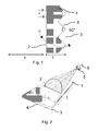
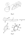
- Figure 3 shows a perfect circular shaped hollow light guide for optimized transport of light.
- This hollow light guide 20 allows transport of light over the distance I, being illuminated in a smooth way.
- the hollow light guide 20 emits light all around the surface. In several special embodiments only a part of the surface of the hollow light guide is visible and therefore only this part must emit light.
- FIG 4 is a first example of a typical turn signal indicator light guide as mounted in vehicle lamps or vehicle's rear view mirrors.
- a typical turn signal indicator light guide as mounted in vehicle lamps or vehicle's rear view mirrors.
- Such a lamp consists of a housing 9 and a lens 10 covering the housing and protecting the interior of the housing from invasive humidity and dust.
- the housing contains all electrical and lighting elements and also light guides at separate parts or integrated into the lens.
- a bulky light guide 7 has a form that follows smoothly the outer contour of the vehicle or the rear view mirror.
- the bulky light guide 7 has the function of a lens 10 too.
- Bulky light guide 7 is shown in a cross section on the left side of the figure. The cross section shows a trapezoid form filled with light guiding material.
- the hollow light guide 20 is formed with an inner wall 12, the side which faces to the housing interior, and an outer wall 11, the side that covers the device to the outer side of the lighting element.
- the two walls are fixed together at surfaces 13, so that they can be easily produced as two molded parts.
- the connecting parts 8 are integrally formed with the wall 12.
- a prismatic structure can be integrated molded producing the walls of the hollow light guide 20.
- Integrated prismatic structures are not easy to realize in conventional molded products, but due to the fact that the light travelling lengths are not high in automotive use the loss of energy by imperfect structures would be acceptable. If better performance is required a prismatic film is preferably used to cover the plan surfaces of the walls 11,12 at the walls outside faces. In Fig. 4 both walls 11 and 12 are covered by the film, in another embodiment the film only covers the inner wall 12 and the visible side of wall 11 is only a smooth surface.
- the prismatic film 1 is fixed by a special optical transparent glue foil or by any welding techniques, as ultrasonic or laser welding.
- the welding points that connect prismatic foil 1 to the walls 11, 12 of the light tube 20 disturb the prismatic structure and are used to couple light out of the light tube.
- the hollow light guide allows a point light source to appear as an area source. Light can also be distributed uniformly to avoid "hot spots" which are often associated with point light sources. In addition, light can be transported from the location of the light source to a remote location where - as an example for a turn signal in a rear view mirror- light must be emitted in a defined angle and power level to follow regulations. So light emitted at the internal end 40 of the lighting element is transported to the end face 41 where the light is projected out to fulfill regulation requirements.
- the lightweight construction of the hollow light guide with reduced wall thickness requires less structural support in the lamp housing.
- the light source is placed apart from the light tube and the prismatic foils so that there is no heat dissipation that could damage the prismatic structure.
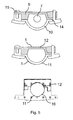
- Fig 5 shows three cross sections of different light guide types.
- a conventional bulky light guide 7 is hosted in a lighting device housing 9.
- the housing is covered by a lens 10, that closes the housing and protects the bulky light guide 7.
- Housing 9 and the lens 10 are connected by connection means as screws 15 or by any other connection 14 such as gluing, or welding or snap-fits, etc.
- a similar structure with the inventional solution is shown in the middle of the figure 5 .
- the bulky light guide is extracted and housing 9 and lens 10 forms in result a hollow light guide 20.
- the light travels in the core area c and is total reflected by walls 12 and 11 of the light tube structure.
- rear side of the wall 12 is covered by a prismatic optical film 1.
- outer side of wall 11 can be also covered at least in part by a prismatic optical film.
- a prismatic optical film At the bottom of fig 5 another example of a hollow light guide is shown.
- the hollow core c is covered by a two part wall structure that forms the circle hollow air gap.
- the inner sides of the wall are coated at least partly with a reflective layer.
- With a metallic layer 16 as an Aluminum layer transport of light in the air gap is possible but with higher energy loss than using prismatic optical films. If the light tube must be visible from outside, only a part of the inner walls will be coated with metal, so that a portion of the light travelling along can be emitted through the wall 11.
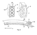
- Figure 6 shows a further embodiment wherein the conventional three bulky light guides are extracted and a hollow light tube is installed.
- the top right part of the figure shows a housing 9 covered by a lens (10. In the housing three parallel bulky light guides are mounted.
- a version of a hollow light guide wherein the bulky light guides are replaces by the hollow tubes is shown.
- the hollow light guides are mounted in the same way as the bulky light guides.
- a cross section of this embodiment along the axis x is shown.
- the hollow light tube 20 is mounted in a housing 9 with posts 17.
- the light source 5 is installed on a printed circuit board 18, that fits into a groove of the housing 9.
- the light of the source 5 is directed into the light tube 20.
- a prismatic optical film 1 is used a protective lens makes sense to optimize the light guiding effect the prismatic optical film is attached to all outer sides of the tube 20.
- the light tube 20 forms the outer lens of the lighting device integrally.
- the use of reflective coatings at the inner walls is a possibility to guide light in the tube.
- the prismatic structures are modified to couple light out in defined directions.
- the decoupling optics can be molded directly to form the hollow light guide.
- prismatic film materials for redirecting light.
- the structure of this film has prism angles at 70° instead of 90°.
- the way in which this film interacts with incident light is quite different.
- the film When the film is positioned so that the groove direction is perpendicular to the direction that the light is traveling within a hollow light guide, light which strikes the groove side of the film at a grazing angle (less than about 20° will be bent 90°.
- This film has found use in helping to achieve uniform light extraction from our internally illuminated signs, as well as in redirecting light in a preferred direction from other hollow light guides.
Landscapes
- Engineering & Computer Science (AREA)
- General Engineering & Computer Science (AREA)
- Physics & Mathematics (AREA)
- General Physics & Mathematics (AREA)
- Optics & Photonics (AREA)
- Lighting Device Outwards From Vehicle And Optical Signal (AREA)
- Non-Portable Lighting Devices Or Systems Thereof (AREA)
Abstract
Description
- The invention is related to a hollow light guide for use in automotive environment to illuminate lighting modules at different positions of the vehicle.
- Several different solutions are known from prior art showing lighted elements at vehicle using light guides molded from plastic materials. The advantage of using a light guide is that the light source and the electrical elements to drive the light source together with the heating issues of a light source can be placed apart from the lighted areas and away from the mirror inner components such as glass backing plate swing arc, etc.
This results in a higher level of design freedom to arrange electrical and lighted elements.
Examples of different designs using light guides are disclosed inUS7255464 . The light guides for turn signal indicators or security lights are bulky elements using PMMA as a preferred material. The thickness of the light guides can be high forming large areas for coupling light in the light guide.
It is also known in industry to use hollow light guides for illumination purposes in such applications as tunnel lights or street lights. But a simple hollow light guide may not totally guide light for reflection conditions and the desired lighting requirements may not be fulfilled. -
EP0789854 of University of British Columbia discloses that prismatic materials could be used to create a "prism light guide," a hollow structure that can efficiently transport large quantities of light. This solution is a pipe whose transparent walls are formed on the outside into precise prismatic facets. The facets are efficient total internal reflection mirrors which prevent light traveling down the guide from escaping. Very little light is absorbed by the pipe because light travels primarily in the air space within the hollow guide. And, because the guide is hollow, weight and cost factors are much more favorable than would be the case with very large solid fibers or rods. The first guides were constructed as disclosed inUS 4787708 as rectangular rigid acrylic pipes with molded-in prisms, and each side of the rigid panel is flat. While the original concept was born from the early dream of piping sunlight to the interiors of artificially lit buildings, it quickly became clear that prism light guides had applicability in a variety of diverse applications and markets.
US 53339382 Figure 1 . The geometry of this film is known as 3M Brand Optical Lighting Film. The material is made from either acrylic or polycarbonate polymer resins which have been especially selected for their physical and optical properties. The acrylic film is more stable in certain adverse environments. Polycarbonate films, on the other hand, are tougher, can operate at higher temperatures, and have better handling properties. Very low light absorption in both materials is the critical feature which allows the film to transport and distribute light efficiently. - It is the intention of the invention to create a lighting device for automotive use with an improved light guiding function and high freedom of design. The disclosed lighting element can be used in head or tail lights; in turn signal indicators positioned in front or rear or in the exterior rear view mirrors, or in lamps in the interior of the vehicle, as illumination source for dash boards or displays.
- The following figures and the description show embodiments of the invention.
-
Figure 1 shows the total reflection in a prismatic film -
Fig. 2 shows the preferred angle of incident light -
Fig. 3 shows a cylindrical light tube -
Fig. 4 shows an example of a turn signal indicator light -
Fig. 5 shows further examples of the hollow light guide -
Fig. 6 shows further examples of the hollow light guide - For automotive use the hollow light guide is quite interesting for it saves material, lowers the relative injection molding cycle time, allows for a remote light location in relation to the mirror bezel and allows a better light guiding function as it is realized in bulky light guides that absorbs much more of the input light energy.
-
Figure 1 shows an example of a prismaticoptical film 1 with is commercially available with a normal thickness of 0.5 mm, having aninternal side 2 facing to the core c of the hollow light guide and anexternal side 3. The light path a) explains the total reflection of light at theprism structures 4. A light beam enters into the prismatic optical film and is deflected according the difference in the diffraction index of the material versus air. The prismatic faces 4 form an angle of 90 degrees. If the incident light beam is entering the prismatic structure with an angle lower than the total reflection angle of the special material set, the beam is totally reflected and travels back into the air gap core c. Path b) shows a light beam emitted out of the core c of the light guiding tube that have walls like the prismaticoptical film 1. For the beam's incident angle is higher than the total reflection angel the beam is diffracted and leaves the light guide tube.
The degree to which the film's prisms shown inFigure 1 deviate from perfect prisms also affects the efficiency of the total internal reflection process, and, therefore, the effectiveness of the film in transporting and distributing light. Of course, the prisms will not be absolutely perfect, so reflectance of the film will not be 100%. Absorption and transmission will occur. Absorption, as was mentioned above, is due in part to bulk absorptivity of the resin used to produce the film, and is an irretrievable loss from the optical system, as the light beams travels in the core c of the light tube and since the projected light only uses the thickness to be reflected, the loss is much lower than in conventional light guides. - Transmission results from imperfections in the form of the surfaces. Examples of these imperfections include 90° corners which are not precise, surfaces which are not optically flat or which deviate from the correct angle, optical inhomogeneities in the material, etc. Transmission, while generally undesirable if not controlled, can be used to advantage if one goal of the application is light distribution. With the typical losses due to absorption and transmission, the reflectance efficiency of prismatic films has been calculated as approaching 99%. Circular hollow light guides can be produced in a variety of sizes which may be required for specific applications.
- Hollow prismatic light pipes act as either a nearly perfect mirror or transparent window depending upon the angle that light strikes the material. For example, the path of a light ray in a flat hollow prism light guide is shown in
Figure 2 . Light enters the device from anexternal light source 5, shown as a lamp inFigure 2 with accompanyingreflector 6. It first strikes the smooth, unstructured side of the film, is refracted according to Snell's law, and passes through the smooth side to strike one of the prism surfaces. If the ray strikes the surface at an angle greater than the critical angle as shown in light path a) ofFig. 1 , it reflects by total internal reflection, and heads for the other prism face. If it reflects again, it returns to the interior of the tube for further propagation. The ray spends relatively little time in the film plastic bulk, especially if the film is thin, and benefits from the low absorption of propagation through air.
Since the reflectivity of the film depends directly upon the angle at which the light rays strike the prism surface, it is obvious that the characteristics of the light source and reflector used to collimate the light are critical to the performance of a prism light guide. For the plastic materials, light must enter the guide at an angle of 27.6° or less from the axis of the guide. In other words, the cone of light from the source should form a 55.2° angle, as shown inFig. 2 - A "perfect" prism light guide would reflect all rays that entered within that 55.2° cone. However, as discussed above, imperfections in the film cause some of the light to be transmitted through the film and escape from the guide, making it glow and illuminating the space around the guide. Generally, in the case of hollow light guides, one attempts to "manage" the rate at which light leaks from the tube, and create uniformity of light escaping along the entire length. One of the most efficient ways to get light out of the tube is to place an additional film (referred to as an "extractor" film) inside the tube to "interrupt" light ray propagation and create uniform light escape from the tube as disclosed in USRE37594. Another method is to simply cut holes in the prismatic film.
-
Figure 3 shows a perfect circular shaped hollow light guide for optimized transport of light. This hollowlight guide 20 allows transport of light over the distance I, being illuminated in a smooth way. For automotive use it is not necessary for all purposes that thehollow light guide 20 emits light all around the surface. In several special embodiments only a part of the surface of the hollow light guide is visible and therefore only this part must emit light. -
Figure 4 is a first example of a typical turn signal indicator light guide as mounted in vehicle lamps or vehicle's rear view mirrors.
Such a lamp consists of ahousing 9 and alens 10 covering the housing and protecting the interior of the housing from invasive humidity and dust. The housing contains all electrical and lighting elements and also light guides at separate parts or integrated into the lens. In the embodiment ofFig.1 a bulkylight guide 7 has a form that follows smoothly the outer contour of the vehicle or the rear view mirror. The bulkylight guide 7 has the function of alens 10 too. Bulkylight guide 7 is shown in a cross section on the left side of the figure. The cross section shows a trapezoid form filled with light guiding material. On top and at the bottom of the light guide core twoarms 8 of the same material forms a connection part to the housing. On the right lower side offigure 4 the disclosed solution is shown in a cross section. Thehollow light guide 20 is formed with aninner wall 12, the side which faces to the housing interior, and anouter wall 11, the side that covers the device to the outer side of the lighting element. The two walls are fixed together atsurfaces 13, so that they can be easily produced as two molded parts. The connectingparts 8 are integrally formed with thewall 12. To improve light travelling along light guide axis x at least a part of the surfaces of the walls are covered by a prismatic structure. The prismatic structure can be integrated molded producing the walls of thehollow light guide 20.
Integrated prismatic structures are not easy to realize in conventional molded products, but due to the fact that the light travelling lengths are not high in automotive use the loss of energy by imperfect structures would be acceptable.
If better performance is required a prismatic film is preferably used to cover the plan surfaces of thewalls Fig. 4 bothwalls inner wall 12 and the visible side ofwall 11 is only a smooth surface. - The
prismatic film 1 is fixed by a special optical transparent glue foil or by any welding techniques, as ultrasonic or laser welding. The welding points that connectprismatic foil 1 to thewalls light tube 20 disturb the prismatic structure and are used to couple light out of the light tube. - The hollow light guide allows a point light source to appear as an area source. Light can also be distributed uniformly to avoid "hot spots" which are often associated with point light sources. In addition, light can be transported from the location of the light source to a remote location where - as an example for a turn signal in a rear view mirror- light must be emitted in a defined angle and power level to follow regulations. So light emitted at the internal end 40 of the lighting element is transported to the end face 41 where the light is projected out to fulfill regulation requirements.
- The lightweight construction of the hollow light guide with reduced wall thickness requires less structural support in the lamp housing. The light source (5 is placed apart from the light tube and the prismatic foils so that there is no heat dissipation that could damage the prismatic structure.
-
Fig 5 shows three cross sections of different light guide types. On the top a conventional bulkylight guide 7 is hosted in alighting device housing 9. The housing is covered by alens 10, that closes the housing and protects the bulkylight guide 7.Housing 9 and thelens 10 are connected by connection means asscrews 15 or by anyother connection 14 such as gluing, or welding or snap-fits, etc.
A similar structure with the inventional solution is shown in the middle of thefigure 5 . The bulky light guide is extracted andhousing 9 andlens 10 forms in result ahollow light guide 20. The light travels in the core area c and is total reflected bywalls wall 12 is covered by a prismaticoptical film 1. And outer side ofwall 11 can be also covered at least in part by a prismatic optical film.
At the bottom offig 5 another example of a hollow light guide is shown. The hollow core c is covered by a two part wall structure that forms the circle hollow air gap. The inner sides of the wall are coated at least partly with a reflective layer. With ametallic layer 16 as an Aluminum layer transport of light in the air gap is possible but with higher energy loss than using prismatic optical films.
If the light tube must be visible from outside, only a part of the inner walls will be coated with metal, so that a portion of the light travelling along can be emitted through thewall 11.
For the length of light tubes in automotive use are short, it is not necessary to design a perfect light guiding tube. Open parts not coated and not covers by prismatic foils can be used to led light shine through. -
Figure 6 shows a further embodiment wherein the conventional three bulky light guides are extracted and a hollow light tube is installed.
The top right part of the figure shows ahousing 9 covered by a lens (10. In the housing three parallel bulky light guides are mounted. - At the left a version of a hollow light guide wherein the bulky light guides are replaces by the hollow tubes is shown. The hollow light guides are mounted in the same way as the bulky light guides.
At the bottom a cross section of this embodiment along the axis x is shown. - The
hollow light tube 20 is mounted in ahousing 9 withposts 17. Thelight source 5 is installed on a printedcircuit board 18, that fits into a groove of thehousing 9. The light of thesource 5 is directed into thelight tube 20. It is possible to have an additional cover lens to protect housing and light guide against environmental influences. Especially if a prismaticoptical film 1 is used a protective lens makes sense to optimize the light guiding effect the prismatic optical film is attached to all outer sides of thetube 20.
In another embodiment thelight tube 20 forms the outer lens of the lighting device integrally.
Alternatively the use of reflective coatings at the inner walls is a possibility to guide light in the tube. - For an optimal appearance the emitted light should be directed. For this purpose the prismatic structures are modified to couple light out in defined directions. The decoupling optics can be molded directly to form the hollow light guide.
Alternatively there are prismatic film materials for redirecting light. The structure of this film has prism angles at 70° instead of 90°. The way in which this film interacts with incident light is quite different. When the film is positioned so that the groove direction is perpendicular to the direction that the light is traveling within a hollow light guide, light which strikes the groove side of the film at a grazing angle (less than about 20° will be bent 90°. This film has found use in helping to achieve uniform light extraction from our internally illuminated signs, as well as in redirecting light in a preferred direction from other hollow light guides.
Claims (11)
- Lighting element for use in automotive environment with a light guiding device mounted to direct light from at least one a light source (5) to at least one decoupling area (41) of the light guide wherein the light guide is made of plastic material , characterized in that the light guide is a hollow light guide (20) with an air gap core (c) limited by at least one wall (11,12), where the light is mainly guided in the air gap core (c ) and the light is at least partly reflected by total reflection effects by the at least one wall (11,12).
- Lighting element according claim 1 characterized in that at least one wall (11, 12) forms a tube (20) with circular or ellipsoid cross section.
- Lighting element according claim 1 characterized in that at least one wall (11,12) forms a cuboid tube (20) with square or trapezoidal cross section.
- Lighting element according claim 1 characterized in that at least one wall (11,12) is at least partly covered by a total reflective prismatic film (1) at the outer sides of the at least one wall.
- Lighting element according claim 1 characterized in that at least one wall (11,12) are at least partly coated by a reflective metallic layer (1).
- Lighting element according claim 1 characterized in that at least one wall (11,12) has a prismatic outer surface molded with the wall as one piece.
- Lighting element according claim 1 characterized in that at least one wall (11,12) of the hollow light guide (20) follows the outer contour of the device in that the lighting element is inserted.
- Lighting element according claim 6 characterized in that the hollow light guide (20) forms a turn signal indicator at a vehicle.
- Lighting element according claim 6 characterized in that the hollow light guide (20) forms a turn signal indicator in a rear view mirror.
- Lighting element according claim 6 characterized in that the hollow light guide (20) forms a part of a lamp in interior of a vehicle.
- Lighting element according claim 1 characterized in that the hollow light guide (20) is formed by two separate pieces of plastic material.
Priority Applications (1)
| Application Number | Priority Date | Filing Date | Title |
|---|---|---|---|
| EP11152473.2A EP2481978B1 (en) | 2011-01-28 | 2011-01-28 | Rear view mirror comprising a hollow light guide |
Applications Claiming Priority (1)
| Application Number | Priority Date | Filing Date | Title |
|---|---|---|---|
| EP11152473.2A EP2481978B1 (en) | 2011-01-28 | 2011-01-28 | Rear view mirror comprising a hollow light guide |
Publications (2)
| Publication Number | Publication Date |
|---|---|
| EP2481978A1 true EP2481978A1 (en) | 2012-08-01 |
| EP2481978B1 EP2481978B1 (en) | 2015-04-08 |
Family
ID=44063455
Family Applications (1)
| Application Number | Title | Priority Date | Filing Date |
|---|---|---|---|
| EP11152473.2A Not-in-force EP2481978B1 (en) | 2011-01-28 | 2011-01-28 | Rear view mirror comprising a hollow light guide |
Country Status (1)
| Country | Link |
|---|---|
| EP (1) | EP2481978B1 (en) |
Cited By (6)
| Publication number | Priority date | Publication date | Assignee | Title |
|---|---|---|---|---|
| EP3336416A1 (en) * | 2016-12-15 | 2018-06-20 | Magna Mirrors Holding GmbH | Illumination unit |
| US10125943B2 (en) | 2014-03-12 | 2018-11-13 | Volkswagen Aktiengesellschaft | Motor vehicle and motor vehicle headlamp with a front housing |
| US10274155B2 (en) | 2013-09-26 | 2019-04-30 | Fico Mirrors, S.A. | Mirror device for motor vehicles and method for assembling thereof |
| DE102018105567A1 (en) * | 2018-03-12 | 2019-09-12 | HELLA GmbH & Co. KGaA | Lighting device for a motor vehicle and method for its production |
| CN114684015A (en) * | 2022-05-10 | 2022-07-01 | 小米汽车科技有限公司 | Blind area alarm system, vehicle and alarm method |
| US11603976B2 (en) | 2021-02-08 | 2023-03-14 | Volkswagen Aktiengesellschaft | Motor vehicle headlamp and method for operating a motor vehicle headlamp |
Citations (7)
| Publication number | Priority date | Publication date | Assignee | Title |
|---|---|---|---|---|
| US4787708A (en) | 1987-05-08 | 1988-11-29 | Tir Systems Ltd. | Apparatus for continuously controlled emission of light from prism light guide |
| US4805984A (en) * | 1985-11-21 | 1989-02-21 | Minnesota Mining And Manufacturing Company | Totally internally reflecting light conduit |
| US5339382A (en) | 1993-02-23 | 1994-08-16 | Minnesota Mining And Manufacturing Company | Prism light guide luminaire with efficient directional output |
| EP0789854A1 (en) | 1994-11-02 | 1997-08-20 | The University Of British Columbia | Hollow light guide for diffuse light |
| DE19740316A1 (en) * | 1997-09-13 | 1999-03-18 | Bosch Gmbh Robert | Automobile lamp unit |
| EP1304260A1 (en) * | 2000-07-12 | 2003-04-23 | Alejandro Rodriguez Barros | Rear-view mirror with multiple interchangeable signals for vehicles with two, three, four or more wheels |
| DE102007033221A1 (en) * | 2007-07-17 | 2008-03-06 | Daimler Ag | Lighting device e.g. brake light, for use in motor vehicle, has multiple LEDs integrated within transparent carrier unit along linear dimension for providing lighting function, and reflectors assigned to LEDs |
Family Cites Families (1)
| Publication number | Priority date | Publication date | Assignee | Title |
|---|---|---|---|---|
| US4260220A (en) * | 1979-06-15 | 1981-04-07 | Canadian Patents And Development Limited | Prism light guide having surfaces which are in octature |
-
2011
- 2011-01-28 EP EP11152473.2A patent/EP2481978B1/en not_active Not-in-force
Patent Citations (8)
| Publication number | Priority date | Publication date | Assignee | Title |
|---|---|---|---|---|
| US4805984A (en) * | 1985-11-21 | 1989-02-21 | Minnesota Mining And Manufacturing Company | Totally internally reflecting light conduit |
| US4787708A (en) | 1987-05-08 | 1988-11-29 | Tir Systems Ltd. | Apparatus for continuously controlled emission of light from prism light guide |
| US5339382A (en) | 1993-02-23 | 1994-08-16 | Minnesota Mining And Manufacturing Company | Prism light guide luminaire with efficient directional output |
| EP0789854A1 (en) | 1994-11-02 | 1997-08-20 | The University Of British Columbia | Hollow light guide for diffuse light |
| DE19740316A1 (en) * | 1997-09-13 | 1999-03-18 | Bosch Gmbh Robert | Automobile lamp unit |
| EP1304260A1 (en) * | 2000-07-12 | 2003-04-23 | Alejandro Rodriguez Barros | Rear-view mirror with multiple interchangeable signals for vehicles with two, three, four or more wheels |
| US7255464B2 (en) | 2000-07-12 | 2007-08-14 | Alejandro Rodriguez Barros | Rear view side mirror with signals emitter device |
| DE102007033221A1 (en) * | 2007-07-17 | 2008-03-06 | Daimler Ag | Lighting device e.g. brake light, for use in motor vehicle, has multiple LEDs integrated within transparent carrier unit along linear dimension for providing lighting function, and reflectors assigned to LEDs |
Cited By (9)
| Publication number | Priority date | Publication date | Assignee | Title |
|---|---|---|---|---|
| US10274155B2 (en) | 2013-09-26 | 2019-04-30 | Fico Mirrors, S.A. | Mirror device for motor vehicles and method for assembling thereof |
| US10125943B2 (en) | 2014-03-12 | 2018-11-13 | Volkswagen Aktiengesellschaft | Motor vehicle and motor vehicle headlamp with a front housing |
| EP3336416A1 (en) * | 2016-12-15 | 2018-06-20 | Magna Mirrors Holding GmbH | Illumination unit |
| US10391932B2 (en) | 2016-12-15 | 2019-08-27 | Magna Mirrors Holding Gmbh | Illumination unit |
| DE102018105567A1 (en) * | 2018-03-12 | 2019-09-12 | HELLA GmbH & Co. KGaA | Lighting device for a motor vehicle and method for its production |
| US11060683B2 (en) | 2018-03-12 | 2021-07-13 | HELLA GmbH & Co. KGaA | Lighting device for a motor vehicle, and method for producing same |
| US11603976B2 (en) | 2021-02-08 | 2023-03-14 | Volkswagen Aktiengesellschaft | Motor vehicle headlamp and method for operating a motor vehicle headlamp |
| CN114684015A (en) * | 2022-05-10 | 2022-07-01 | 小米汽车科技有限公司 | Blind area alarm system, vehicle and alarm method |
| CN114684015B (en) * | 2022-05-10 | 2024-01-02 | 小米汽车科技有限公司 | Blind spot alarm system, vehicle and alarm method |
Also Published As
| Publication number | Publication date |
|---|---|
| EP2481978B1 (en) | 2015-04-08 |
Similar Documents
| Publication | Publication Date | Title |
|---|---|---|
| EP2481978B1 (en) | Rear view mirror comprising a hollow light guide | |
| US7695179B2 (en) | Illuminating device | |
| CN104428586B (en) | Lighting unit for a headlight | |
| US9574734B2 (en) | Lightguide module | |
| US4805984A (en) | Totally internally reflecting light conduit | |
| CN104566110B (en) | Lighting apparatus with light directing device | |
| CN100468101C (en) | Light guiding device and method of guiding light | |
| US5369554A (en) | Illuminator utilizing multiple light guides | |
| JP2011198537A (en) | Lamp tool for vehicle | |
| US7357548B2 (en) | Light-guiding system comprising a number of light transmission rods | |
| EP1664866B1 (en) | A light-guiding system comprising a plate-like light-emitting element | |
| CN215174803U (en) | A lens that emits light from three sides | |
| US20060285808A1 (en) | Light-guiding system comprising a plate-like triangular guiding member | |
| KR100794350B1 (en) | Lighting system with light guide | |
| KR20200079862A (en) | lamp for vehicle | |
| CN209928053U (en) | Light emitting structure and lighting system | |
| CN213656654U (en) | Light guide column structure for laser illumination | |
| CN218954704U (en) | Light guide device, car lamp assembly and vehicle | |
| CN224080024U (en) | Optical modules, lighting devices and motor vehicles | |
| KR101000061B1 (en) | Light pipe and lighting device having same | |
| JP2874886B2 (en) | Beam splitter | |
| CN120176055A (en) | Light guide element, lighting device and vehicle | |
| JP2025068531A (en) | Light guide, and vehicular lighting tool | |
| JP2000138002A (en) | Light guides for vehicle lighting | |
| KR20120109164A (en) | Pof for lighting and its method of processing, lighting apparatus using for pof and its method of manufacturing |
Legal Events
| Date | Code | Title | Description |
|---|---|---|---|
| PUAI | Public reference made under article 153(3) epc to a published international application that has entered the european phase |
Free format text: ORIGINAL CODE: 0009012 |
|
| 17P | Request for examination filed |
Effective date: 20110720 |
|
| AK | Designated contracting states |
Kind code of ref document: A1 Designated state(s): AL AT BE BG CH CY CZ DE DK EE ES FI FR GB GR HR HU IE IS IT LI LT LU LV MC MK MT NL NO PL PT RO RS SE SI SK SM TR |
|
| AX | Request for extension of the european patent |
Extension state: BA ME |
|
| 17Q | First examination report despatched |
Effective date: 20131007 |
|
| GRAP | Despatch of communication of intention to grant a patent |
Free format text: ORIGINAL CODE: EPIDOSNIGR1 |
|
| INTG | Intention to grant announced |
Effective date: 20141120 |
|
| GRAS | Grant fee paid |
Free format text: ORIGINAL CODE: EPIDOSNIGR3 |
|
| GRAA | (expected) grant |
Free format text: ORIGINAL CODE: 0009210 |
|
| AK | Designated contracting states |
Kind code of ref document: B1 Designated state(s): AL AT BE BG CH CY CZ DE DK EE ES FI FR GB GR HR HU IE IS IT LI LT LU LV MC MK MT NL NO PL PT RO RS SE SI SK SM TR |
|
| REG | Reference to a national code |
Ref country code: GB Ref legal event code: FG4D |
|
| REG | Reference to a national code |
Ref country code: CH Ref legal event code: EP |
|
| REG | Reference to a national code |
Ref country code: IE Ref legal event code: FG4D |
|
| REG | Reference to a national code |
Ref country code: AT Ref legal event code: REF Ref document number: 720868 Country of ref document: AT Kind code of ref document: T Effective date: 20150515 |
|
| REG | Reference to a national code |
Ref country code: DE Ref legal event code: R096 Ref document number: 602011015363 Country of ref document: DE Effective date: 20150521 |
|
| REG | Reference to a national code |
Ref country code: AT Ref legal event code: MK05 Ref document number: 720868 Country of ref document: AT Kind code of ref document: T Effective date: 20150408 |
|
| REG | Reference to a national code |
Ref country code: NL Ref legal event code: VDEP Effective date: 20150408 |
|
| REG | Reference to a national code |
Ref country code: LT Ref legal event code: MG4D |
|
| PG25 | Lapsed in a contracting state [announced via postgrant information from national office to epo] |
Ref country code: NL Free format text: LAPSE BECAUSE OF FAILURE TO SUBMIT A TRANSLATION OF THE DESCRIPTION OR TO PAY THE FEE WITHIN THE PRESCRIBED TIME-LIMIT Effective date: 20150408 |
|
| PG25 | Lapsed in a contracting state [announced via postgrant information from national office to epo] |
Ref country code: NO Free format text: LAPSE BECAUSE OF FAILURE TO SUBMIT A TRANSLATION OF THE DESCRIPTION OR TO PAY THE FEE WITHIN THE PRESCRIBED TIME-LIMIT Effective date: 20150708 Ref country code: HR Free format text: LAPSE BECAUSE OF FAILURE TO SUBMIT A TRANSLATION OF THE DESCRIPTION OR TO PAY THE FEE WITHIN THE PRESCRIBED TIME-LIMIT Effective date: 20150408 Ref country code: PT Free format text: LAPSE BECAUSE OF FAILURE TO SUBMIT A TRANSLATION OF THE DESCRIPTION OR TO PAY THE FEE WITHIN THE PRESCRIBED TIME-LIMIT Effective date: 20150810 Ref country code: LT Free format text: LAPSE BECAUSE OF FAILURE TO SUBMIT A TRANSLATION OF THE DESCRIPTION OR TO PAY THE FEE WITHIN THE PRESCRIBED TIME-LIMIT Effective date: 20150408 Ref country code: ES Free format text: LAPSE BECAUSE OF FAILURE TO SUBMIT A TRANSLATION OF THE DESCRIPTION OR TO PAY THE FEE WITHIN THE PRESCRIBED TIME-LIMIT Effective date: 20150408 Ref country code: FI Free format text: LAPSE BECAUSE OF FAILURE TO SUBMIT A TRANSLATION OF THE DESCRIPTION OR TO PAY THE FEE WITHIN THE PRESCRIBED TIME-LIMIT Effective date: 20150408 |
|
| PG25 | Lapsed in a contracting state [announced via postgrant information from national office to epo] |
Ref country code: AT Free format text: LAPSE BECAUSE OF FAILURE TO SUBMIT A TRANSLATION OF THE DESCRIPTION OR TO PAY THE FEE WITHIN THE PRESCRIBED TIME-LIMIT Effective date: 20150408 Ref country code: RS Free format text: LAPSE BECAUSE OF FAILURE TO SUBMIT A TRANSLATION OF THE DESCRIPTION OR TO PAY THE FEE WITHIN THE PRESCRIBED TIME-LIMIT Effective date: 20150408 Ref country code: IS Free format text: LAPSE BECAUSE OF FAILURE TO SUBMIT A TRANSLATION OF THE DESCRIPTION OR TO PAY THE FEE WITHIN THE PRESCRIBED TIME-LIMIT Effective date: 20150808 Ref country code: GR Free format text: LAPSE BECAUSE OF FAILURE TO SUBMIT A TRANSLATION OF THE DESCRIPTION OR TO PAY THE FEE WITHIN THE PRESCRIBED TIME-LIMIT Effective date: 20150709 Ref country code: LV Free format text: LAPSE BECAUSE OF FAILURE TO SUBMIT A TRANSLATION OF THE DESCRIPTION OR TO PAY THE FEE WITHIN THE PRESCRIBED TIME-LIMIT Effective date: 20150408 |
|
| REG | Reference to a national code |
Ref country code: DE Ref legal event code: R097 Ref document number: 602011015363 Country of ref document: DE |
|
| REG | Reference to a national code |
Ref country code: FR Ref legal event code: PLFP Year of fee payment: 6 |
|
| PG25 | Lapsed in a contracting state [announced via postgrant information from national office to epo] |
Ref country code: EE Free format text: LAPSE BECAUSE OF FAILURE TO SUBMIT A TRANSLATION OF THE DESCRIPTION OR TO PAY THE FEE WITHIN THE PRESCRIBED TIME-LIMIT Effective date: 20150408 Ref country code: DK Free format text: LAPSE BECAUSE OF FAILURE TO SUBMIT A TRANSLATION OF THE DESCRIPTION OR TO PAY THE FEE WITHIN THE PRESCRIBED TIME-LIMIT Effective date: 20150408 |
|
| PLBE | No opposition filed within time limit |
Free format text: ORIGINAL CODE: 0009261 |
|
| STAA | Information on the status of an ep patent application or granted ep patent |
Free format text: STATUS: NO OPPOSITION FILED WITHIN TIME LIMIT |
|
| PG25 | Lapsed in a contracting state [announced via postgrant information from national office to epo] |
Ref country code: SK Free format text: LAPSE BECAUSE OF FAILURE TO SUBMIT A TRANSLATION OF THE DESCRIPTION OR TO PAY THE FEE WITHIN THE PRESCRIBED TIME-LIMIT Effective date: 20150408 Ref country code: RO Free format text: LAPSE BECAUSE OF NON-PAYMENT OF DUE FEES Effective date: 20150408 Ref country code: CZ Free format text: LAPSE BECAUSE OF FAILURE TO SUBMIT A TRANSLATION OF THE DESCRIPTION OR TO PAY THE FEE WITHIN THE PRESCRIBED TIME-LIMIT Effective date: 20150408 Ref country code: PL Free format text: LAPSE BECAUSE OF FAILURE TO SUBMIT A TRANSLATION OF THE DESCRIPTION OR TO PAY THE FEE WITHIN THE PRESCRIBED TIME-LIMIT Effective date: 20150408 |
|
| 26N | No opposition filed |
Effective date: 20160111 |
|
| PG25 | Lapsed in a contracting state [announced via postgrant information from national office to epo] |
Ref country code: IT Free format text: LAPSE BECAUSE OF FAILURE TO SUBMIT A TRANSLATION OF THE DESCRIPTION OR TO PAY THE FEE WITHIN THE PRESCRIBED TIME-LIMIT Effective date: 20150408 |
|
| PG25 | Lapsed in a contracting state [announced via postgrant information from national office to epo] |
Ref country code: BE Free format text: LAPSE BECAUSE OF NON-PAYMENT OF DUE FEES Effective date: 20160131 Ref country code: SI Free format text: LAPSE BECAUSE OF FAILURE TO SUBMIT A TRANSLATION OF THE DESCRIPTION OR TO PAY THE FEE WITHIN THE PRESCRIBED TIME-LIMIT Effective date: 20150408 |
|
| PG25 | Lapsed in a contracting state [announced via postgrant information from national office to epo] |
Ref country code: LU Free format text: LAPSE BECAUSE OF FAILURE TO SUBMIT A TRANSLATION OF THE DESCRIPTION OR TO PAY THE FEE WITHIN THE PRESCRIBED TIME-LIMIT Effective date: 20160128 Ref country code: BE Free format text: LAPSE BECAUSE OF FAILURE TO SUBMIT A TRANSLATION OF THE DESCRIPTION OR TO PAY THE FEE WITHIN THE PRESCRIBED TIME-LIMIT Effective date: 20150408 |
|
| REG | Reference to a national code |
Ref country code: CH Ref legal event code: PL |
|
| PG25 | Lapsed in a contracting state [announced via postgrant information from national office to epo] |
Ref country code: MC Free format text: LAPSE BECAUSE OF FAILURE TO SUBMIT A TRANSLATION OF THE DESCRIPTION OR TO PAY THE FEE WITHIN THE PRESCRIBED TIME-LIMIT Effective date: 20150408 |
|
| PG25 | Lapsed in a contracting state [announced via postgrant information from national office to epo] |
Ref country code: LI Free format text: LAPSE BECAUSE OF NON-PAYMENT OF DUE FEES Effective date: 20160131 Ref country code: CH Free format text: LAPSE BECAUSE OF NON-PAYMENT OF DUE FEES Effective date: 20160131 |
|
| REG | Reference to a national code |
Ref country code: IE Ref legal event code: MM4A |
|
| REG | Reference to a national code |
Ref country code: FR Ref legal event code: PLFP Year of fee payment: 7 |
|
| PG25 | Lapsed in a contracting state [announced via postgrant information from national office to epo] |
Ref country code: IE Free format text: LAPSE BECAUSE OF NON-PAYMENT OF DUE FEES Effective date: 20160128 |
|
| PG25 | Lapsed in a contracting state [announced via postgrant information from national office to epo] |
Ref country code: SE Free format text: LAPSE BECAUSE OF FAILURE TO SUBMIT A TRANSLATION OF THE DESCRIPTION OR TO PAY THE FEE WITHIN THE PRESCRIBED TIME-LIMIT Effective date: 20150408 |
|
| PG25 | Lapsed in a contracting state [announced via postgrant information from national office to epo] |
Ref country code: MT Free format text: LAPSE BECAUSE OF FAILURE TO SUBMIT A TRANSLATION OF THE DESCRIPTION OR TO PAY THE FEE WITHIN THE PRESCRIBED TIME-LIMIT Effective date: 20150408 |
|
| REG | Reference to a national code |
Ref country code: FR Ref legal event code: PLFP Year of fee payment: 8 |
|
| PG25 | Lapsed in a contracting state [announced via postgrant information from national office to epo] |
Ref country code: CY Free format text: LAPSE BECAUSE OF FAILURE TO SUBMIT A TRANSLATION OF THE DESCRIPTION OR TO PAY THE FEE WITHIN THE PRESCRIBED TIME-LIMIT Effective date: 20150408 Ref country code: HU Free format text: LAPSE BECAUSE OF FAILURE TO SUBMIT A TRANSLATION OF THE DESCRIPTION OR TO PAY THE FEE WITHIN THE PRESCRIBED TIME-LIMIT; INVALID AB INITIO Effective date: 20110128 Ref country code: SM Free format text: LAPSE BECAUSE OF FAILURE TO SUBMIT A TRANSLATION OF THE DESCRIPTION OR TO PAY THE FEE WITHIN THE PRESCRIBED TIME-LIMIT Effective date: 20150408 |
|
| PG25 | Lapsed in a contracting state [announced via postgrant information from national office to epo] |
Ref country code: MT Free format text: LAPSE BECAUSE OF FAILURE TO SUBMIT A TRANSLATION OF THE DESCRIPTION OR TO PAY THE FEE WITHIN THE PRESCRIBED TIME-LIMIT Effective date: 20160131 Ref country code: MK Free format text: LAPSE BECAUSE OF FAILURE TO SUBMIT A TRANSLATION OF THE DESCRIPTION OR TO PAY THE FEE WITHIN THE PRESCRIBED TIME-LIMIT Effective date: 20150408 Ref country code: TR Free format text: LAPSE BECAUSE OF FAILURE TO SUBMIT A TRANSLATION OF THE DESCRIPTION OR TO PAY THE FEE WITHIN THE PRESCRIBED TIME-LIMIT Effective date: 20150408 |
|
| PG25 | Lapsed in a contracting state [announced via postgrant information from national office to epo] |
Ref country code: BG Free format text: LAPSE BECAUSE OF FAILURE TO SUBMIT A TRANSLATION OF THE DESCRIPTION OR TO PAY THE FEE WITHIN THE PRESCRIBED TIME-LIMIT Effective date: 20150408 |
|
| PG25 | Lapsed in a contracting state [announced via postgrant information from national office to epo] |
Ref country code: AL Free format text: LAPSE BECAUSE OF FAILURE TO SUBMIT A TRANSLATION OF THE DESCRIPTION OR TO PAY THE FEE WITHIN THE PRESCRIBED TIME-LIMIT Effective date: 20150408 |
|
| REG | Reference to a national code |
Ref country code: DE Ref legal event code: R084 Ref document number: 602011015363 Country of ref document: DE |
|
| PGFP | Annual fee paid to national office [announced via postgrant information from national office to epo] |
Ref country code: FR Payment date: 20230124 Year of fee payment: 13 |
|
| PGFP | Annual fee paid to national office [announced via postgrant information from national office to epo] |
Ref country code: GB Payment date: 20230119 Year of fee payment: 13 |
|
| P01 | Opt-out of the competence of the unified patent court (upc) registered |
Effective date: 20230616 |
|
| PGFP | Annual fee paid to national office [announced via postgrant information from national office to epo] |
Ref country code: DE Payment date: 20240119 Year of fee payment: 14 |
|
| GBPC | Gb: european patent ceased through non-payment of renewal fee |
Effective date: 20240128 |
|
| PG25 | Lapsed in a contracting state [announced via postgrant information from national office to epo] |
Ref country code: GB Free format text: LAPSE BECAUSE OF NON-PAYMENT OF DUE FEES Effective date: 20240128 |
|
| PG25 | Lapsed in a contracting state [announced via postgrant information from national office to epo] |
Ref country code: FR Free format text: LAPSE BECAUSE OF NON-PAYMENT OF DUE FEES Effective date: 20240131 |
|
| PG25 | Lapsed in a contracting state [announced via postgrant information from national office to epo] |
Ref country code: GB Free format text: LAPSE BECAUSE OF NON-PAYMENT OF DUE FEES Effective date: 20240128 Ref country code: FR Free format text: LAPSE BECAUSE OF NON-PAYMENT OF DUE FEES Effective date: 20240131 |
|
| REG | Reference to a national code |
Ref country code: DE Ref legal event code: R119 Ref document number: 602011015363 Country of ref document: DE |
|
| PG25 | Lapsed in a contracting state [announced via postgrant information from national office to epo] |
Ref country code: DE Free format text: LAPSE BECAUSE OF NON-PAYMENT OF DUE FEES Effective date: 20250801 |