EP2481904A1 - Anti-idling device and anti-idling function disabling method - Google Patents
Anti-idling device and anti-idling function disabling method Download PDFInfo
- Publication number
- EP2481904A1 EP2481904A1 EP10818754A EP10818754A EP2481904A1 EP 2481904 A1 EP2481904 A1 EP 2481904A1 EP 10818754 A EP10818754 A EP 10818754A EP 10818754 A EP10818754 A EP 10818754A EP 2481904 A1 EP2481904 A1 EP 2481904A1
- Authority
- EP
- European Patent Office
- Prior art keywords
- microcomputer
- reset
- voltage
- idling stop
- established
- Prior art date
- Legal status (The legal status is an assumption and is not a legal conclusion. Google has not performed a legal analysis and makes no representation as to the accuracy of the status listed.)
- Granted
Links
Images




Classifications
-
- F—MECHANICAL ENGINEERING; LIGHTING; HEATING; WEAPONS; BLASTING
- F02—COMBUSTION ENGINES; HOT-GAS OR COMBUSTION-PRODUCT ENGINE PLANTS
- F02D—CONTROLLING COMBUSTION ENGINES
- F02D29/00—Controlling engines, such controlling being peculiar to the devices driven thereby, the devices being other than parts or accessories essential to engine operation, e.g. controlling of engines by signals external thereto
- F02D29/02—Controlling engines, such controlling being peculiar to the devices driven thereby, the devices being other than parts or accessories essential to engine operation, e.g. controlling of engines by signals external thereto peculiar to engines driving vehicles; peculiar to engines driving variable pitch propellers
-
- F—MECHANICAL ENGINEERING; LIGHTING; HEATING; WEAPONS; BLASTING
- F02—COMBUSTION ENGINES; HOT-GAS OR COMBUSTION-PRODUCT ENGINE PLANTS
- F02N—STARTING OF COMBUSTION ENGINES; STARTING AIDS FOR SUCH ENGINES, NOT OTHERWISE PROVIDED FOR
- F02N11/00—Starting of engines by means of electric motors
- F02N11/08—Circuits specially adapted for starting of engines
- F02N11/0814—Circuits specially adapted for starting of engines comprising means for controlling automatic idle-start-stop
- F02N11/0818—Conditions for starting or stopping the engine or for deactivating the idle-start-stop mode
- F02N11/0825—Conditions for starting or stopping the engine or for deactivating the idle-start-stop mode related to prevention of engine restart failure, e.g. disabling automatic stop at low battery state
-
- F—MECHANICAL ENGINEERING; LIGHTING; HEATING; WEAPONS; BLASTING
- F02—COMBUSTION ENGINES; HOT-GAS OR COMBUSTION-PRODUCT ENGINE PLANTS
- F02N—STARTING OF COMBUSTION ENGINES; STARTING AIDS FOR SUCH ENGINES, NOT OTHERWISE PROVIDED FOR
- F02N11/00—Starting of engines by means of electric motors
- F02N11/08—Circuits specially adapted for starting of engines
- F02N11/0862—Circuits specially adapted for starting of engines characterised by the electrical power supply means, e.g. battery
-
- F—MECHANICAL ENGINEERING; LIGHTING; HEATING; WEAPONS; BLASTING
- F02—COMBUSTION ENGINES; HOT-GAS OR COMBUSTION-PRODUCT ENGINE PLANTS
- F02N—STARTING OF COMBUSTION ENGINES; STARTING AIDS FOR SUCH ENGINES, NOT OTHERWISE PROVIDED FOR
- F02N2250/00—Problems related to engine starting or engine's starting apparatus
- F02N2250/02—Battery voltage drop at start, e.g. drops causing ECU reset
-
- F—MECHANICAL ENGINEERING; LIGHTING; HEATING; WEAPONS; BLASTING
- F02—COMBUSTION ENGINES; HOT-GAS OR COMBUSTION-PRODUCT ENGINE PLANTS
- F02N—STARTING OF COMBUSTION ENGINES; STARTING AIDS FOR SUCH ENGINES, NOT OTHERWISE PROVIDED FOR
- F02N2300/00—Control related aspects of engine starting
- F02N2300/30—Control related aspects of engine starting characterised by the use of digital means
-
- Y—GENERAL TAGGING OF NEW TECHNOLOGICAL DEVELOPMENTS; GENERAL TAGGING OF CROSS-SECTIONAL TECHNOLOGIES SPANNING OVER SEVERAL SECTIONS OF THE IPC; TECHNICAL SUBJECTS COVERED BY FORMER USPC CROSS-REFERENCE ART COLLECTIONS [XRACs] AND DIGESTS
- Y02—TECHNOLOGIES OR APPLICATIONS FOR MITIGATION OR ADAPTATION AGAINST CLIMATE CHANGE
- Y02T—CLIMATE CHANGE MITIGATION TECHNOLOGIES RELATED TO TRANSPORTATION
- Y02T10/00—Road transport of goods or passengers
- Y02T10/10—Internal combustion engine [ICE] based vehicles
- Y02T10/40—Engine management systems
Definitions
- the invention relates to an idling stop technology of automatically stopping/starting an engine of a vehicle.
- an idling stop apparatus In recent years, in order to save the fuel or to reduce the exhaust gas, an idling stop apparatus has been put to practical use which automatically stops/starts an engine of a vehicle while the vehicle is stopped for relatively short time such as waiting at stoplights.
- a stop condition for example when the vehicle is shifted from a traveling state to a stopped state as the brake is stepped, the engine is automatically stopped, and when a start condition is established, for example when the brake is released while the engine is stopped, the engine is enabled to automatically start (for example, refer to Patent Document 1).
- Patent Document 1 Japanese Patent Application Publication No. 2009-13953
- the power of respective units of the vehicle is fed from a battery that is provided to the vehicle.
- the battery is charged by using rotating force of the engine.
- a voltage of the battery is lowered, it may be difficult to feed the power to the respective units of the vehicle. Therefore, in order not to lower the voltage of the battery, it is preferable not to stop the vehicle to the extent possible.
- the voltage of the battery is lowered somewhat, it is preferable to disable the idling stop function of automatically stopping the engine.
- the idling stop function is realized by a microcomputer that is provided to the idling stop apparatus. Accordingly, a configuration is considered in which the microcomputer monitors the voltage of the battery and disables the idling stop function when the voltage of the battery is lowered below a predetermined threshold.
- the power that drives a starter motor for starting the engine is fed from the battery.
- the power for operating the microcomputer of the idling stop apparatus is also fed from the battery via a decreasing regulator.
- the microcomputer of the idling stop apparatus disables the idling stop function.
- the microcomputer when the voltage of the battery is remarkably lowered below a minimum operating voltage of the microcomputer, the microcomputer cannot be operated and is reset. Thereby, since the microcomputer having restarted after the reset cannot figure out the voltage of the battery before the reset, the microcomputer enables the idling stop function. As a result, even though the voltage of the battery has been considerably lowered, the automatic stop of the engine is executed, so that the voltage of the battery may be further lowered.
- An object of the invention is to provide a technology capable of preventing a voltage of a battery from being lowered even after a microcomputer of an idling stop apparatus is reset.
- the object of the invention is realized by following configurations.
- the storage includes only one logic circuit capable of storing information of 1 bit.
- the storage deletes the reset information when detecting an ignition switch of the vehicle is turned off.
- the storage starts operating in a state of storing the reset information when a voltage applied to the storage transits from a state below a minimum operating voltage of the storage to a state above the minimum operating voltage of the storage, and the minimum operating voltage of the storage is higher than a reference voltage which is used for detecting the ignition switch is turned on.
- a minimum operating voltage of the microcomputer is higher than a minimum operating voltage of the storage.
- the detector detects that the reset condition is established on the basis of a power-supply voltage of the microcomputer, which is obtained by decreasing a voltage of a battery of the vehicle.
- the detector detects that the reset condition is established on the basis of both the power-supply voltage of the microcomputer and the voltage of the battery.
- the power-supply voltage of the microcomputer is obtained by decreasing the voltage of the battery by a plurality of decreasing units, and the detector detects that that the reset condition is established on the basis of both the power-supply voltage of the microcomputer and a voltage between the decreasing units.
- An idling stop apparatus to be mounted on a vehicle including a microcomputer having an idling stop function of automatically stopping an engine of the vehicle when a predetermined stop condition is established and of automatically starting the engine when a predetermined start condition is established while the engine is stopped, a detector that detects that a power-supply voltage of the microcomputer becomes below a minimum operating voltage of the microcomputer, and a prohibiting unit that prohibits the microcomputer from executing the idling stop function after the microcomputer is reset when the detector detects that the power-supply voltage of the microcomputer becomes below the minimum operating voltage of the microcomputer.
- the microcomputer when the reset condition is established, the reset information indicating that the reset condition is established is stored, and when the reset information is stored, the microcomputer disables the idling stop function. Since the reset information is stored even when the microcomputer is being reset, the microcomputer can disable the idling stop function after the reset. As a result, it is possible to prevent the voltage of the battery from being lowered due to the idling stop function.
- the reset information is deleted. Therefore, it is possible to enable the idling stop function when a user gets in the vehicle next time.
- the storage starts operating in a state of storing the reset information and the minimum operating voltage of the storage is higher than a reference voltage that is used for detecting the ignition switch is turned on. Accordingly, even when an operating power-supply voltage of the storage is lowered below the minimum operating voltage, it is possible to disable the idling stop function.
- a minimum operating voltage of the microcomputer is higher than a minimum operating voltage of the storage. Therefore, even when an operating power-supply voltage of the storage is lowered below the minimum operating voltage, since the storage securely operates when the microcomputer restarts, it is possible to perform a stable operation.
- the reset condition when the reset condition is established due to a cause except for the voltage drop of the battery, such as ground fault of a power-supply voltage of the microcomputer, it is possible to prevent the idling stop function from being disabled. Also, since the voltage between the plurality of decreasing units, rather than the voltage of the battery, is detected, it is possible to stably detect that the reset condition is established, without the influence of the noise, compared to a configuration of directly detecting the voltage of the battery.
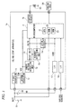
- FIG. 1 is a block diagram showing a configuration of an idling stop apparatus 1a of a first illustrative embodiment and peripheral elements thereof.
- the idling stop apparatus 1a is mounted on a vehicle such as automobile and has a function of automatically stopping/starting an engine of the vehicle while the vehicle is stopped for relatively short time such as waiting at stoplights.
- the vehicle on which the idling stop apparatus 1a is mounted has a battery 51, and power is fed from the battery 51 to respective units of the vehicle such as starter motor of the engine, idling stop apparatus 1a and the like.
- the idling stop apparatus 1a consists of an ECU (Electronic Control Unit) and has a microcomputer 2 as a main constitutional element.
- the microcomputer 2 has a CPU 21, a RAM 22 and a ROM 23.
- a variety of functions of the microcomputer 2 are implemented as the CPU 21 performs calculation processing in response to programs pre-stored in the ROM 23.
- the functions of the microcomputer 2 include the idling stop function and a function of disabling the idling stop function.
- the idling stop function is a function of automatically stopping/starting an engine of the vehicle in response to a traveling state of the vehicle.
- Signals indicating the traveling state of the vehicle are input to the microcomputer 2 from various sensors mounted on the vehicle through an interface 18. Specifically, vehicle speed from a vehicle speed sensor, a position of a shift lever from a shift sensor, an operation content of an accelerator from an accelerator sensor and an operation content of a brake from a brake sensor are respectively input as signals.
- the engine is stopped by the idling stop function. For example, when a variety of conditions such as 'vehicle speed is zero (0)', 'shift lever is positioned at D', 'there is no accelerator operation' and 'there is a brake operation' are satisfied, it is determined that the stop condition is established.
- the microcomputer 2 transmits a predetermined stop signal to an engine ECU 54 that controls the engine. The engine ECU 54 stops the engine in response to the stop signal.
- the engine automatically starts by the idling stop function. For example, when a variety of conditions such as 'shift lever is positioned at D', 'there is an accelerator operation' and 'there is no brake operation' are satisfied, it is determined that the start condition is established.
- the microcomputer 2 transmits a predetermined start signal to a starter control circuit 16 of the idling stop apparatus 1a.
- the starter control circuit 16 energizes a coil 53 in response to the signal. When the coil 53 is energized, a relay switch is closed and the power is thus fed from the battery 51 to the starter motor, so that the engine starts.
- the disabling function of the microcomputer 2 is a function of disabling the idling stop function.
- the idling stop function is disabled by the disabling function of the microcomputer 2.
- the voltage of the battery 51 of the vehicle is input, as a digital value, to the microcomputer 2.
- the microcomputer 2 stores a minimum value of the voltages of the battery 51, which are input in real time, in the RAM 22. Then, when the voltage of the battery 51 stored in the RAM 22 is lowered below a predetermined threshold, the microcomputer 2 disables the idling stop function thereafter. For example, a usual voltage of the battery 51 is 12V. However, when the voltage of the battery 51 becomes below 5V, the idling stop function is disabled. Since the minimum value of the voltage of the battery 51 is stored in the RAM 22 that is a volatile memory, when the microcomputer 2 is reset, the minimum value is deleted.
- the idling stop function is disabled by the disabling function of the microcomputer 2, which will be specifically described later.
- the idling stop apparatus 1a has, as a power-supply circuit of the microcomputer 2, two regulators (first regulator 11 and second regulator 12) that decrease an input voltage to a constant voltage.
- the first regulator 11 is configured by a switching regulator that can decrease a voltage relatively largely.
- the second regulator 12 is configured by a series regulator that can decrease a voltage to a desired voltage in high precision.
- the power of the microcomputer 2 is fed from the battery 51 of the vehicle. While an ideal value of the power-supply voltage of the microcomputer 2 is 5V, a usual voltage of the battery 51 is 12V. Therefore, in the idling stop apparatus 1a, a voltage BATT (ideal value: 12V) of the battery 51 is decreased to a predetermined voltage VIN (ideal value: 6V) in the first regulator 11, which is then further decreased in the second regulator 12 and thus the power-supply voltage VCC (ideal value: 5V) of the microcomputer 2 is obtained in high precision.
- VIN ideal value: 6V
- the regulators 11, 12 regulate an output voltage within a range in which an input voltage is an upper limit.
- the output voltage is also lowered below a desired voltage. That is, when the voltage BATT of the battery is lowered, the voltage VIN that is obtained by the decreasing in the first regulator 11 and the voltage VCC (the power-supply voltage of the microcomputer 2) that is obtained by the decreasing in the second regulator 11 are also lowered.
- the idling stop apparatus 1a has, as a circuit for resetting the microcomputer 2, an under voltage detection unit 13, a reset unit 14 and a runaway detection unit 15.
- the under voltage detection unit 13 is connected to a power feed line from the second regulator 12 to the microcomputer 2 and monitors the power-supply voltage VCC of the microcomputer 2.
- the under voltage detection unit When the power-supply voltage VCC of the microcomputer 2 becomes below a minimum operating voltage with which the microcomputer 2 can operate, the under voltage detection unit outputs an instruction signal to the rest unit 14, which signal indicates that a reset should be made.
- the minimum operating voltage of the microcomputer 2 is indicated with a symbol Vt and is 3.9V, for example.
- the under voltage detection unit 13 has a comparator 131.
- a non-inverting input terminal (+) of the comparator 131 is applied with a predetermined reference voltage Vr1.
- an inverting input terminal (-) of the comparator 131 is applied with a voltage that is obtained by dividing the power-supply voltage VCC of the microcomputer 2 by two resistances 132, 133.
- an "H" signal is output, as the instruction signal, from an output terminal of the comparator 131.
- the power-supply voltage VCC of the microcomputer 2 becomes below the minimum operating voltage Vt of the microcomputer 2.
- the runaway detection unit 15 detects whether the microcomputer 2 is in a runaway state such as freeze.
- the runaway detection unit 15 monitors an operation signal of a watch dog timer of the microcomputer 2, for example. When a regular signal is not detected, the runaway detection unit determines that the microcomputer 2 is in a runaway state. In this case, the microcomputer 2 cannot restore the function thereof unless it is reset. Accordingly, the runaway detection unit 15 determines that a reset condition for resetting the microcomputer 2 is established and outputs an instruction signal to the reset unit 14, which signal indicates that the reset should be made.
- the reset unit 14 outputs a reset signal INITB, which instructs the microcomputer 2 on the reset.
- the reset signal INITB is usually "H”.
- the reset signal becomes "L” the microcomputer 2 is instructed for the reset.
- the reset unit 14 sets the reset signal INITB to be "L.”
- the microcomputer 2 monitors the reset signal INITB all the time and is reset when the reset signal INITB becomes “L.” That is, the microcomputer 2 stops the operation once and then restarts.
- the idling stop apparatus 1a has a latch circuit 3a that, when the reset condition is established, for example when the power-supply voltage VCC of the microcomputer 2 becomes below the minimum operating voltage Vt, stores information indicating that reset condition is established. Irrespective of the states of the microcomputer 2, the latch circuit 3a stores the information indicating that the reset condition is established even when the microcomputer 2 is being reset. Thereby, it is possible to inform the microcomputer 2 having restarted after the reset that the power-supply voltage VCC of the microcomputer 2 becomes below the minimum operating voltage Vt before the reset.
- the latch circuit 3a is input with the reset signal INITB from the reset unit 14. Together this, the latch circuit 3a is input with an ignition signal IGSW from an ignition line downstream from an ignition switch 52 through an interface 17.
- the ignition signal IGSW indicates on/off states of the ignition switch 52 that is operated by a user so as to travel the vehicle. When the ignition switch 52 is ON, the ignition signal becomes "H” and when the ignition switch 52 is OFF, the ignition signal becomes "L.”
- FIG. 2 shows a configuration of the latch circuit 3a together with the peripheral constitutional elements thereof.
- the latch circuit 3a has an RS type flip-flop 4 that is a logic circuit capable of storing information of 1 bit, a NOT circuit 31 and a comparator 32.
- FIG. 3 shows an example of a configuration of the flip-flop 4.
- the flip-flop 4 has four NPN-type transistors 41 to 44, and emitters thereof are grounded.
- a base of the first transistor 41 is a set input terminal S and a base of the fourth transistor 44 is a reset input terminal R.
- Collectors of the first transistor 41 and the second transistor 42 are connected to each other and are connected to a power-supply line 48 through a diode 47 and a resistance 45. Also, the collectors of the first transistor 41 and the second transistor 42 and a base of the third transistor 43 are connected to each other.
- collectors of the third transistor 43 and the fourth transistor 44 are also connected to each other and are connected to the power-supply line 48 through a resistance 46. Also, the collectors of the third transistor 43 and the fourth transistor 44 and a base of the second transistor 42 are connected to each other. Voltages of the collectors of the third transistor 43 and the fourth transistor 44 become a voltage of an output terminal Q of the flip-flop 4.
- the power-supply voltage VCC of the microcomputer 2 is applied.
- the flip-flop 4 stops the operation thereof when the operating power-supply voltage becomes below a predetermined minimum operating voltage.
- the minimum operating voltage of the flip-flop 4 is indicated by a symbol Vu and is 1.6V, for example.
- the flip-flop 4 when operating power-supply voltage of the flip-flop 4 transits from a state below the minimum operating voltage Vu to a state above the minimum operating voltage, the flip-flop 4 starts the operation thereof.
- the flip-flop 4 is configured to output "H" from the output terminal Q at the start time of the operation.
- a current path from the power-supply line 48 to the ground includes a first path passing to the diode 47, the resistance 45 and between the base and emitter of the third transistor 43 and a second path passing to the resistance 46 and between the base and emitter of the second transistor 42.
- the set input terminal S of the flip-flop 4 is connected with an output terminal of the NOT circuit 31.
- An input terminal of the NOT circuit 31 is input with the reset signal INITB that is output from the reset unit 14. Therefore, the set input terminal S of the flip-flop 4 is input with an inverted signal of the reset signal INITB.
- the reset signal INITB becomes "L.” Therefore, when the reset condition is established, "H” is input to the set input terminal S of the flip-flop 4 and a latch signal SG from the output terminal Q of the flip-flop 4 becomes “H.” Like this, the state in which the latch signal SG from the output terminal Q becomes "H” indicates a state in which information (hereinafter, also referred to as 'reset information') indicating that reset condition is established is stored in the flip-flop 4.
- 'reset information' information
- the reset input terminal R of the flip-flop 4 is connected with an output terminal of the comparator 32.
- the non-inverting input terminal (+) of the comparator 32 is applied with a predetermined reference voltage Vre and the inverting terminal (-) is input with the ignition signal IGSW.
- the reference voltage Vre is lower than the "H” voltage of the ignition signal IGSW and is 1.25V, for example.
- the reset input terminal R of the flip-flop 4 is input with “L” when the ignition switch 52 is turned on and is input with “H” when the ignition switch is turned off. Therefore, when the ignition switch 52 is turned off, the latch signal SG from the output terminal Q of the flip-flop 4 becomes “L.” That is, when the ignition switch 52 is turned off, the reset information is deleted from the flip-flop 4.
- the reset information is stored in the flip-flop 4 and the latch signal SG from the output terminal Q becomes "H.” Since the flip-flop 4 is not influenced by the operation of the microcomputer 2, the reset information is stored in the flip-flop 4 even when the microcomputer 2 is being reset or even after the reset. While the reset information is stored in the flip-flop 4, the latch signal SG from the output terminal Q becomes "H.” Then, when the ignition switch 52 is turned off, the reset information is deleted from the flip-flop 4 and the latch signal SG from the output terminal Q becomes "L.”
- the "H" latch signal SG that is output from the flip-flop 4 is input to the microcomputer 2. Thereby, it is possible to inform the microcomputer 2 having restarted after the reset that the reset condition has been established before the reset. More specifically, it is possible to inform the microcomputer 2 after the reset that the power-supply voltage VCC of the microcomputer 2 becomes below the minimum operating voltage Vt.
- the microcomputer 2 monitors the latch signal SG from the flip-flop 4 of the latch circuit 3a.
- the latch signal SG is "L”
- the microcomputer 2 enables the idling stop function.
- the latch signal SG is "H”
- the microcomputer 2 disables the idling stop function by the disabling function.
- the power-supply voltage VCC of the microcomputer 2 becomes below the minimum operating voltage Vt
- the microcomputer 2 disables the idling stop function after the microcomputer 2 is reset.
- the "H" latch signal SG that is output from the flip-flop 4 of the latch circuit 3a is a prohibiting signal that prohibits the microcomputer 2 from executing the idling stop function after the microcomputer 2 is reset.
- a disabling condition is any one of a first condition that the voltage of the battery 51 is lowered below a predetermined threshold and a second condition that a prohibiting signal is output from the latch circuit 3a.
- the case where a prohibiting signal is output from the latch circuit 3a indicates a case where the reset information is stored in the flip-flop 4 of the latch circuit 3a.
- the first condition is applied, so that the idling stop function of the microcomputer 2 is disabled.
- the power-supply voltage of the microcomputer 2 also becomes below the minimum operating voltage Vt (for example, 3.9V) of the microcomputer 2 and the microcomputer 2 is thus reset.
- the microcomputer 2 When the microcomputer 2 is reset as described above, the content (minimum value of the voltage of the battery 51) of the RAM 22 of the microcomputer 2 is deleted. Hence, the first condition is not applied. In the meantime, the reset information is stored in the flip-flop 4, so that a prohibiting signal is output from the latch circuit 3a. Therefore, the second condition is applied, so that the idling stop function of the microcomputer 2 is disabled even after the reset.
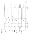
- FIG. 4 is a timing chart showing changes of various signals when the voltage of the battery 51 is lowered at the start time of the engine and the microcomputer 2 is thus reset.
- the ignition switch 52 is turned off and the engine is not started.
- the ignition signal IGSW becomes "L”
- a signal FF_RESET that is applied to the reset input terminal R of the flip-flop 4 of the latch circuit 3a becomes "H.” Therefore, the stored content of the flip-flop 4 is deleted.
- the ignition switch 52 is turned on by a user's operation. Thereby, the voltage VB of the ignition line downstream from the ignition switch 52 is increased and the ignition switch IGSW becomes "H.” Also, the under voltage detection unit 13 having the ignition line as a power-supply line starts up and the reset signal INITB of "H" is output from the reset unit 14. Also, as the ignition signal IGSW becomes "H”, the signal FF_RESET that is applied to the reset input terminal R of the flip-flop 4 becomes “L.”
- the start switch is turned on by the user's operation and the power is fed to the starter motor, so that the engine starts.
- the voltage BATT of the battery 51 is lowered.
- all the power lines to which the power is fed from the battery 51 are influenced. Accordingly, the voltage VB of the ignition line and the power-supply voltage VCC of the microcomputer 2 are also lowered.
- the under voltage detection unit 13 detects the corresponding state and outputs an instruction signal to the reset unit 14. Thereby, the reset unit 14 sets the reset signal INITB to be "L.” Thereby, the microcomputer 2 stops the operation thereof for reset.
- the reset unit 14 sets the reset signal INITB to be "H" and the microcomputer 2 restarts.
- the reset information indicating that the reset condition is established is stored in the latch circuit 3a and the microcomputer 2 disables the idling stop function while the reset information is stored. Since the reset information is stored in the latch circuit 3a even when the microcomputer 2 is being reset and even after the reset, the microcomputer 2 after the reset can disable the idling stop function. As a result, it is possible to prevent the voltage of the battery 51 from being lowered due to the idling stop function.
- the latch circuit 3a deletes the reset information of the flip-flop 4. Accordingly, it is possible to enable the idling stop function when getting in the vehicle next time.
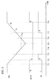
- FIG. 5 is a timing chart showing changes of the reset signal INITB and the latch signal SG from the flip-flop 4 when the operating power-supply voltage VCC of the flip-flop 4 is lowered below the minimum operating voltage Vu.
- the ignition switch 52 is turned on but the engine is not started (a state between time T1 and time T2).
- the engine starts by the user's operation.
- the voltage of the battery 51 is lowered and the power-supply voltage VCC of the microcomputer 2 is also lowered from time T11. Up to time T18, the voltage of the battery 51 and the power-supply voltage VCC of the microcomputer 2 are the substantially same.
- the reset unit 14 sets the reset signal INITB to be "L". Thereby, the microcomputer 2 stops the operation thereof for reset.
- the "H" signal FF_SET is input to the set input terminal S of the flip-flop 4 of the latch circuit 3a, so that the reset information is stored in the flip-flop 4.
- the latch signal SG that is output from the flip-flop 4 becomes "H.”
- Vre for example, 1.25V
- the engine starts, so that the voltage of the battery 51 or power-supply voltage VCC of the microcomputer 2 starts to increase at time T15.
- the on state of the ignition switch 52 is detected.
- the signal FF_RESET that is applied to the reset input terminal R of the flip-flop 4 becomes "L.”
- the flip-flop 4 starts the operation thereof.
- the flip-flop 4 is configured to output the "H" latch signal SG at the start time of the operation. Therefore, the flip-flop 4 starts the operation with the reset information being stored therein.
- the reset information is not deleted.
- the microcomputer 2 restarts. Since the minimum operating voltage Vt of the microcomputer 2 is higher than the minimum operating voltage Vu of the flip-flop 4, the flip-flop 4 starts the operation thereof at the restarting time at a state in which the flip-flop has already output the "H" latch signal SG (prohibiting signal). Therefore, it is possible to securely output the prohibiting signal to the microcomputer 2 having restarted, so that the idling stop apparatus 1a can perform the stable operation. Thereby, the idling stop function is disabled in the microcomputer 2 having restarted.
- the flip-flop 4 of the latch circuit 3a starts the operation thereof with the reset information being stored therein.
- the minimum operating voltage Vu of the flip-flop 4 is higher than the reference voltage Vre that is compared so as to detect the on/off states of the ignition switch, the reset information is not deleted at the start time T17 of the operation of the flip-flop 4. Therefore, even when the operating power-supply voltage VCC of the flip-flop 4 is lowered below the minimum operating voltage Vu and thus the flip-flop 4 stops the operation thereof, the reset information is not deleted, so that it is possible to disable the idling stop function without any problem.
- the latch circuit 3a monitors the reset signal INITB, thereby indirectly detecting that the power-supply voltage VCC of the microcomputer 2 becomes below the minimum operating voltage Vt.
- the idling stop function may be disabled even when the reset condition is established due to the runaway of the microcomputer 2 and the like, rather than the voltage lowering of the battery 51.
- the idling stop function may be disabled even when the power-supply voltage VCC of the microcomputer 2 is lowered due to a cause except for the voltage lowering of the battery 51, for example a ground fault that occurs in a power-supply line that feeds the power from the second regulator 12 to the microcomputer 2, the idling stop function may be disabled.
- the second illustrative embodiment is configured to cope with the above situations.
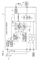
- FIG. 6 is a block diagram showing a configuration of an idling stop apparatus 1b of the second illustrative embodiment and peripheral elements thereof.
- the configuration of the idling stop apparatus 1b is the substantially same as the idling stop apparatus 1a of the first illustrative embodiment but has two under voltage detection units 13, 19.
- the first under voltage detection unit 13 is the same as the under voltage detection unit 13 of the first illustrative embodiment and monitors the power-supply voltage VCC of the microcomputer 2.
- the second under voltage detection unit 19 is adapted to monitor the voltage BATT of the battery 51.
- a latch circuit 3b of this illustrative embodiment is input with an output signal from the first under voltage detection unit 13 and an output signal from the second under voltage detection unit 19, instead of the reset signal INITB.
- the configuration in which the ignition signal IGSW is input to the latch circuit 3b is the same as the first illustrative embodiment.
- FIG. 7 shows a configuration of the latch circuit 3b of the second illustrative embodiment together with the peripheral constitutional elements thereof.
- the second under voltage detection unit 19 has the substantially same configuration as the first under voltage detection unit 13 and includes a comparator 191.
- a non-inverting input terminal (+) of the comparator 191 is applied with a predetermined reference voltage Vr2.
- an inverting input terminal (-) of the comparator 191 is applied with a voltage that is obtained by dividing the voltage BATT of the battery 51 by two resistances 192, 193.
- the latch circuit 3b has the flip-flop 4, an AND circuit 33 and the comparator 32.
- the flip-flop 4 and the comparator 32 are the same as those of the first illustrative embodiment.
- the set input terminal S of the flip-flop 4 is connected with an output terminal of the comparator 33.
- the AND circuit 33 is input with both an output signal from the first under voltage detection unit 13 and an output signal from the second under voltage detection unit 19.
- the power-supply voltage VCC of the microcomputer 2 is directly monitored, rather than the reset signal INITB, so that it is detected that the reset condition is established. Therefore, when the reset condition is established due to a cause except for the voltage drop, such as runaway of the microcomputer 2, it is possible to prevent the idling stop function from being disabled.
- the reset condition is established by monitoring both the power-supply voltage VCC of the microcomputer 2 and the voltage BATT of the battery 51. Therefore, when the power-supply voltage VCC of the microcomputer 2 is lowered due to a cause except for the voltage drop of the battery 51, for example a ground fault that occurs in the power-supply line that feeds the power to the microcomputer 2, it is possible to prevent the idling stop function from being disabled.
- FIG. 8 is a block diagram showing a configuration of an idling stop apparatus 1c of the third illustrative embodiment and peripheral elements thereof. Also, FIG. 9 shows a configuration of the latch circuit 3b of the third illustrative embodiment together with the peripheral constitutional elements thereof.
- the configuration and operation of the idling stop apparatus 1c of the third illustrative embodiment are the substantially same as those of the idling stop apparatus 1b of the second illustrative embodiment.
- the second under voltage detection unit 19 is adapted to monitor the voltage BATT of the battery 51.
- the second under voltage detection unit 19 monitors the voltage VIN that is obtained by lowering the voltage BATT of the battery 51 in the first regulator 11. That is, the voltage VIN between the first regulator 11 and the second regulator 12 is monitored. Since a distance between the first regulator 11 and the second regulator 12 is relatively close, there is a very low possibility that a ground fault will occur at the corresponding position.
- the voltage VIN is also lowered. Accordingly, it is possible to detect the voltage lowering of the battery 51 by monitoring the voltage VIN.
- the power-supply voltage VCC of the microcomputer 2 is lowered due to a cause except for the voltage drop of the battery 51, it is possible to prevent the idling stop function from being disabled.
- the voltage BATT of the battery 51 is susceptible to the other parts mounted on the vehicle, so that there is a high possibility that a noise will be caused therein. Therefore, by monitoring the voltage VIN that is obtained by decreasing the voltage BATT of the battery 51 in the first regulator 11, it is possible to reduce the influence of the noise. Hence, compared to the configuration in which the voltage BATT of the battery 51 is directly monitored, it is possible to stably detect that the reset condition is established.
- the flip-flop 4 is configured to output the "H" latch signal SG at the start time of the operation. Compared to this, the flip-flop 4 may be configured to output the "L" latch signal SG at the start time of the operation.
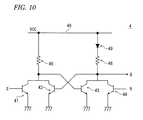
- FIG. 10 shows an example of the configuration of the flip-flop 4.
- the flip-flop 4 is the substantially same as the flip-flop 4 shown in FIG. 3 .
- the diode 47 is not provided between the collectors of the first transistor 41 and second transistor 42 and the power-supply line 48.
- a diode 49 is provided between the collectors of the third transistor 43 and fourth transistor 44 and the power-supply line 48.
- a current path from the power-supply line 48 to the ground includes a first path passing to the resistance 45 and between the base and emitter of the third transistor 43 and a second path passing to the diode 49, the resistance 46 and between the base and emitter of the second transistor 42.
- the reset unit 14 sets the reset signal INITB to be "L.” Thereby, the microcomputer 2 stops the operation thereof for reset.
- the "H” signal FF_SET is input to the set input terminal S of the flip-flop 4 of the latch circuit 3a and the reset information is stored in the flip-flop 4. Then, the latch signal SG that is output from the flip-flop 4 becomes "H.”
- the flip-flop 4 stops the operation thereof.
- the flip-flop 4 starts the operation thereof.
- the flip-flop 4 is configured to output the "L" latch signal SG. Therefore, the flip-flop 4 starts the operation with the reset information not being stored.
- the microcomputer 2 restarts.
- the minimum operating voltage Vt of the microcomputer 2 is higher than the minimum operating voltage Vu of the flip-flop 4 and the flip-flop 4 outputs the "H" latch signal SG (prohibiting signal) at the restart time. Therefore, it is possible to securely output the prohibiting signal to the microcomputer 2, so that the idling stop apparatus can perform the stable operation.
- both the power-supply voltage VCC of the microcomputer 2 and the voltage BATT of the battery 51 are monitored. However, only one voltage may be monitored.
- both the power-supply voltage VCC of the microcomputer 2 and the voltage VIN between the first regulator 11 and the second regulator 12 are monitored. However, only one voltage may be monitored.
- the third illustrative embodiment there are provided two regulators that decrease the voltage of the battery 51. However, when three or more regulators are provided, a voltage between any two regulators may be monitored.
- a memory having a relatively large storage capacity may be adopted.
- the various functions are software-implemented by the calculation processing of the CPU in response to the programs.
- parts of the functions may be implemented by an electrical hardware circuit.
- a part of functions that are implemented by the hardware circuit may be software-implemented.
Landscapes
- Engineering & Computer Science (AREA)
- Chemical & Material Sciences (AREA)
- Combustion & Propulsion (AREA)
- Mechanical Engineering (AREA)
- General Engineering & Computer Science (AREA)
- Control Of Vehicle Engines Or Engines For Specific Uses (AREA)
- Combined Controls Of Internal Combustion Engines (AREA)
- Power Sources (AREA)
Abstract
Description
- The invention relates to an idling stop technology of automatically stopping/starting an engine of a vehicle.
- In recent years, in order to save the fuel or to reduce the exhaust gas, an idling stop apparatus has been put to practical use which automatically stops/starts an engine of a vehicle while the vehicle is stopped for relatively short time such as waiting at stoplights. For a vehicle having the idling stop apparatus, when a stop condition is established, for example when the vehicle is shifted from a traveling state to a stopped state as the brake is stepped, the engine is automatically stopped, and when a start condition is established, for example when the brake is released while the engine is stopped, the engine is enabled to automatically start (for example, refer to Patent Document 1).
- Patent Document 1: Japanese Patent Application Publication No.
2009-13953 - The power of respective units of the vehicle is fed from a battery that is provided to the vehicle. However, the battery is charged by using rotating force of the engine. When a voltage of the battery is lowered, it may be difficult to feed the power to the respective units of the vehicle. Therefore, in order not to lower the voltage of the battery, it is preferable not to stop the vehicle to the extent possible. Hence, when the voltage of the battery is lowered somewhat, it is preferable to disable the idling stop function of automatically stopping the engine.
- The idling stop function is realized by a microcomputer that is provided to the idling stop apparatus. Accordingly, a configuration is considered in which the microcomputer monitors the voltage of the battery and disables the idling stop function when the voltage of the battery is lowered below a predetermined threshold.
- Meanwhile, the power that drives a starter motor for starting the engine is fed from the battery. Likewise, the power for operating the microcomputer of the idling stop apparatus is also fed from the battery via a decreasing regulator.
- Since the power that the starter motor requires for the engine start is very high, the voltage of the battery is remarkably lowered at the start time of the engine. When the lowered voltage of the battery is lowered below a predetermined threshold, it is preferable that the microcomputer of the idling stop apparatus disables the idling stop function.
- However, when the voltage of the battery is remarkably lowered below a minimum operating voltage of the microcomputer, the microcomputer cannot be operated and is reset. Thereby, since the microcomputer having restarted after the reset cannot figure out the voltage of the battery before the reset, the microcomputer enables the idling stop function. As a result, even though the voltage of the battery has been considerably lowered, the automatic stop of the engine is executed, so that the voltage of the battery may be further lowered.
- The invention has been made to solve the above problems. An object of the invention is to provide a technology capable of preventing a voltage of a battery from being lowered even after a microcomputer of an idling stop apparatus is reset.
- The object of the invention is realized by following configurations.
- (1) An idling stop apparatus to be mounted on a vehicle, including a microcomputer having an idling stop function of automatically stopping an engine of the vehicle when a predetermined stop condition is established and of automatically starting the engine when a predetermined start condition is established while the engine is stopped, a detector that detects that a reset condition for resetting the microcomputer is established, and a storage that stores reset information which indicates that the reset condition is established when the detector detects that the reset condition is established even when the microcomputer is being reset, wherein the microcomputer disables the idling stop function when the storage stores the reset information.
- (2) In the idling stop apparatus described in the above (1), the storage includes only one logic circuit capable of storing information of 1 bit.
- (3) In the idling stop apparatus described in the above (1) or (2), the storage deletes the reset information when detecting an ignition switch of the vehicle is turned off.
- (4) In the idling stop apparatus described in the above (3), the storage starts operating in a state of storing the reset information when a voltage applied to the storage transits from a state below a minimum operating voltage of the storage to a state above the minimum operating voltage of the storage, and the minimum operating voltage of the storage is higher than a reference voltage which is used for detecting the ignition switch is turned on.
- (5) In the idling stop apparatus described in one of the above (1) to (4), a minimum operating voltage of the microcomputer is higher than a minimum operating voltage of the storage.
- (6) In the idling stop apparatus described in one of the above (1) to (5), the detector detects that the reset condition is established on the basis of a power-supply voltage of the microcomputer, which is obtained by decreasing a voltage of a battery of the vehicle.
- (7) In the idling stop apparatus described in the above (6), the detector detects that the reset condition is established on the basis of both the power-supply voltage of the microcomputer and the voltage of the battery.
- (8) In the idling stop apparatus described in the above (6), the power-supply voltage of the microcomputer is obtained by decreasing the voltage of the battery by a plurality of decreasing units, and the detector detects that that the reset condition is established on the basis of both the power-supply voltage of the microcomputer and a voltage between the decreasing units.
- (9) An idling stop apparatus to be mounted on a vehicle, including a microcomputer having an idling stop function of automatically stopping an engine of the vehicle when a predetermined stop condition is established and of automatically starting the engine when a predetermined start condition is established while the engine is stopped, a detector that detects that a power-supply voltage of the microcomputer becomes below a minimum operating voltage of the microcomputer, and a prohibiting unit that prohibits the microcomputer from executing the idling stop function after the microcomputer is reset when the detector detects that the power-supply voltage of the microcomputer becomes below the minimum operating voltage of the microcomputer.
- (10) A method for disabling an idling stop function of automatically stopping an engine of a vehicle when a predetermined stop condition is established and of automatically starting the engine when a predetermined start condition is established while the engine is stopped, detecting that a reset condition for resetting a microcomputer having the idling stop function is established, storing reset information which indicates that the reset condition is established when detecting that the reset condition is established even when the microcomputer is being reset, and disabling the idling stop function of the microcomputer when the reset information is stored.
- (11) A method for disabling an idling stop function of automatically stopping an engine of a vehicle when a predetermined stop condition is established and of automatically starting the engine when a predetermined start condition is established while the engine is stopped, detecting that a power-supply voltage of a microcomputer having the idling stop function becomes below a minimum operating voltage of the microcomputer, prohibiting the microcomputer from executing the idling stop function after the microcomputer is reset when detecting that the power-supply voltage of the microcomputer becomes below the minimum operating voltage of the microcomputer.
- According to the configurations of the above (1) to (8) and (10), when the reset condition is established, the reset information indicating that the reset condition is established is stored, and when the reset information is stored, the microcomputer disables the idling stop function. Since the reset information is stored even when the microcomputer is being reset, the microcomputer can disable the idling stop function after the reset. As a result, it is possible to prevent the voltage of the battery from being lowered due to the idling stop function.
- Also, in particular, according to the configuration of the above (2), it is possible to realize the idling stop apparatus at low cost.
- Also, in particular, according to the configuration of the above (3), when the ignition switch is turned off, the reset information is deleted. Therefore, it is possible to enable the idling stop function when a user gets in the vehicle next time.
- Also, in particular, according to the configuration of the above (4), the storage starts operating in a state of storing the reset information and the minimum operating voltage of the storage is higher than a reference voltage that is used for detecting the ignition switch is turned on. Accordingly, even when an operating power-supply voltage of the storage is lowered below the minimum operating voltage, it is possible to disable the idling stop function.
- Also, in particular, according to the configuration of the above (5), a minimum operating voltage of the microcomputer is higher than a minimum operating voltage of the storage. Therefore, even when an operating power-supply voltage of the storage is lowered below the minimum operating voltage, since the storage securely operates when the microcomputer restarts, it is possible to perform a stable operation.
- Also, in particular, according to the configuration of the above (6), when the reset condition is established due to a cause except for the voltage drop of the battery, such as runaway of the microcomputer, it is possible to prevent the idling stop function from being disabled.
- Also, in particular, according to the configuration of the above (7), when the reset condition is established due to a cause except for the voltage drop of the battery, such as ground fault of a power-supply line of the microcomputer, it is possible to prevent the idling stop function from being disabled.
- Also, in particular, according to the configuration of the above (8), when the reset condition is established due to a cause except for the voltage drop of the battery, such as ground fault of a power-supply voltage of the microcomputer, it is possible to prevent the idling stop function from being disabled. Also, since the voltage between the plurality of decreasing units, rather than the voltage of the battery, is detected, it is possible to stably detect that the reset condition is established, without the influence of the noise, compared to a configuration of directly detecting the voltage of the battery.
- Also, in particular, according to the configurations of the above (9) and (11), when a power-supply voltage of the microcomputer becomes below a minimum operating voltage of the microcomputer, the execution of the idling stop function is prohibited after the microcomputer is reset. Accordingly, it is possible to prevent the voltage of the battery from being lowered due to the idling stop function.
-
-
FIG. 1 shows a configuration of an idling stop apparatus according to a first illustrative embodiment. -
FIG. 2 shows a configuration of a latch circuit of the first illustrative embodiment. -
FIG. 3 shows an example of a configuration of a flip-flop of the first illustrative embodiment. -
FIG. 4 shows changes of various signals when a voltage of a battery is lowered. -
FIG. 5 shows changes of various signals when a voltage of a battery is lowered. -
FIG. 6 shows a configuration of an idling stop apparatus according to a second illustrative embodiment. -
FIG. 7 shows a configuration of a latch circuit of the second illustrative embodiment. -
FIG. 8 shows a configuration of an idling stop apparatus according to a third illustrative embodiment. -
FIG. 9 shows a configuration of a latch circuit of the third illustrative embodiment. -
FIG. 10 shows a configuration of a flip-flop of a fourth illustrative embodiment. - Hereinafter, illustrative embodiments of the invention will be described with reference to the drawings.
-
FIG. 1 is a block diagram showing a configuration of an idlingstop apparatus 1a of a first illustrative embodiment and peripheral elements thereof. The idlingstop apparatus 1a is mounted on a vehicle such as automobile and has a function of automatically stopping/starting an engine of the vehicle while the vehicle is stopped for relatively short time such as waiting at stoplights. The vehicle on which the idlingstop apparatus 1a is mounted has abattery 51, and power is fed from thebattery 51 to respective units of the vehicle such as starter motor of the engine, idlingstop apparatus 1a and the like. - The idling
stop apparatus 1a consists of an ECU (Electronic Control Unit) and has amicrocomputer 2 as a main constitutional element. Themicrocomputer 2 has aCPU 21, aRAM 22 and aROM 23. A variety of functions of themicrocomputer 2 are implemented as theCPU 21 performs calculation processing in response to programs pre-stored in theROM 23. The functions of themicrocomputer 2 include the idling stop function and a function of disabling the idling stop function. - The idling stop function is a function of automatically stopping/starting an engine of the vehicle in response to a traveling state of the vehicle. Signals indicating the traveling state of the vehicle are input to the
microcomputer 2 from various sensors mounted on the vehicle through aninterface 18. Specifically, vehicle speed from a vehicle speed sensor, a position of a shift lever from a shift sensor, an operation content of an accelerator from an accelerator sensor and an operation content of a brake from a brake sensor are respectively input as signals. - When a predetermined stop condition is established on the basis of the signals indicating the traveling state, the engine is stopped by the idling stop function. For example, when a variety of conditions such as 'vehicle speed is zero (0)', 'shift lever is positioned at D', 'there is no accelerator operation' and 'there is a brake operation' are satisfied, it is determined that the stop condition is established. When stopping the engine, the
microcomputer 2 transmits a predetermined stop signal to anengine ECU 54 that controls the engine. Theengine ECU 54 stops the engine in response to the stop signal. - Also, when a predetermined start condition is established on the basis of the signals indicating the traveling state while the engine is stopped by the idling stop function, the engine automatically starts by the idling stop function. For example, when a variety of conditions such as 'shift lever is positioned at D', 'there is an accelerator operation' and 'there is no brake operation' are satisfied, it is determined that the start condition is established. When starting the engine, the
microcomputer 2 transmits a predetermined start signal to astarter control circuit 16 of the idlingstop apparatus 1a. Thestarter control circuit 16 energizes acoil 53 in response to the signal. When thecoil 53 is energized, a relay switch is closed and the power is thus fed from thebattery 51 to the starter motor, so that the engine starts. - The disabling function of the
microcomputer 2 is a function of disabling the idling stop function. When the voltage of thebattery 51 is lowered, it may hinder the power feeding to the respective units of the vehicle. Therefore, it is preferable not to stop the engine to the extent possible so that the voltage of thebattery 51 is not lowered. Thus, when it is determined that the voltage of thebattery 51 is lowered below a predetermined threshold, the idling stop function is disabled by the disabling function of themicrocomputer 2. - The voltage of the
battery 51 of the vehicle is input, as a digital value, to themicrocomputer 2. Themicrocomputer 2 stores a minimum value of the voltages of thebattery 51, which are input in real time, in theRAM 22. Then, when the voltage of thebattery 51 stored in theRAM 22 is lowered below a predetermined threshold, themicrocomputer 2 disables the idling stop function thereafter. For example, a usual voltage of thebattery 51 is 12V. However, when the voltage of thebattery 51 becomes below 5V, the idling stop function is disabled. Since the minimum value of the voltage of thebattery 51 is stored in theRAM 22 that is a volatile memory, when themicrocomputer 2 is reset, the minimum value is deleted. - Also, when a predetermined signal is input from a
latch circuit 3a that will be described later, the idling stop function is disabled by the disabling function of themicrocomputer 2, which will be specifically described later. - The idling
stop apparatus 1a has, as a power-supply circuit of themicrocomputer 2, two regulators (first regulator 11 and second regulator 12) that decrease an input voltage to a constant voltage. Thefirst regulator 11 is configured by a switching regulator that can decrease a voltage relatively largely. In the meantime, thesecond regulator 12 is configured by a series regulator that can decrease a voltage to a desired voltage in high precision. - The power of the
microcomputer 2 is fed from thebattery 51 of the vehicle. While an ideal value of the power-supply voltage of themicrocomputer 2 is 5V, a usual voltage of thebattery 51 is 12V. Therefore, in the idlingstop apparatus 1a, a voltage BATT (ideal value: 12V) of thebattery 51 is decreased to a predetermined voltage VIN (ideal value: 6V) in thefirst regulator 11, which is then further decreased in thesecond regulator 12 and thus the power-supply voltage VCC (ideal value: 5V) of themicrocomputer 2 is obtained in high precision. - In the meantime, the
regulators first regulator 11 and the voltage VCC (the power-supply voltage of the microcomputer 2) that is obtained by the decreasing in thesecond regulator 11 are also lowered. - Also, the idling
stop apparatus 1a has, as a circuit for resetting themicrocomputer 2, an undervoltage detection unit 13, areset unit 14 and arunaway detection unit 15. - The under
voltage detection unit 13 is connected to a power feed line from thesecond regulator 12 to themicrocomputer 2 and monitors the power-supply voltage VCC of themicrocomputer 2. When the power-supply voltage VCC of themicrocomputer 2 becomes below a minimum operating voltage with which themicrocomputer 2 can operate, the under voltage detection unit outputs an instruction signal to therest unit 14, which signal indicates that a reset should be made. In the descriptions, the minimum operating voltage of themicrocomputer 2 is indicated with a symbol Vt and is 3.9V, for example. - As shown in
FIG. 2 , the undervoltage detection unit 13 has acomparator 131. A non-inverting input terminal (+) of thecomparator 131 is applied with a predetermined reference voltage Vr1. In the meantime, an inverting input terminal (-) of thecomparator 131 is applied with a voltage that is obtained by dividing the power-supply voltage VCC of themicrocomputer 2 by tworesistances comparator 131. At this time, the power-supply voltage VCC of themicrocomputer 2 becomes below the minimum operating voltage Vt of themicrocomputer 2. - When the power-supply voltage VCC of the
microcomputer 2 becomes below the minimum operating voltage Vt, themicrocomputer 2 cannot operate. Therefore, it can be said that the case where the power-supply voltage VCC of themicrocomputer 2 becomes below the minimum operating voltage Vt indicates that a reset condition for resetting themicrocomputer 2 is established. - Returning to
FIG. 1 , therunaway detection unit 15 detects whether themicrocomputer 2 is in a runaway state such as freeze. Therunaway detection unit 15 monitors an operation signal of a watch dog timer of themicrocomputer 2, for example. When a regular signal is not detected, the runaway detection unit determines that themicrocomputer 2 is in a runaway state. In this case, themicrocomputer 2 cannot restore the function thereof unless it is reset. Accordingly, therunaway detection unit 15 determines that a reset condition for resetting themicrocomputer 2 is established and outputs an instruction signal to thereset unit 14, which signal indicates that the reset should be made. - The
reset unit 14 outputs a reset signal INITB, which instructs themicrocomputer 2 on the reset. The reset signal INITB is usually "H". When the reset signal becomes "L", themicrocomputer 2 is instructed for the reset. When the reset condition is established and thus an instruction signal indicating that a reset should be made is input from any one of the undervoltage detection unit 13 and therunaway detection unit 15, thereset unit 14 sets the reset signal INITB to be "L." Themicrocomputer 2 monitors the reset signal INITB all the time and is reset when the reset signal INITB becomes "L." That is, themicrocomputer 2 stops the operation once and then restarts. - Also, the idling
stop apparatus 1a has alatch circuit 3a that, when the reset condition is established, for example when the power-supply voltage VCC of themicrocomputer 2 becomes below the minimum operating voltage Vt, stores information indicating that reset condition is established. Irrespective of the states of themicrocomputer 2, thelatch circuit 3a stores the information indicating that the reset condition is established even when themicrocomputer 2 is being reset. Thereby, it is possible to inform themicrocomputer 2 having restarted after the reset that the power-supply voltage VCC of themicrocomputer 2 becomes below the minimum operating voltage Vt before the reset. - The
latch circuit 3a is input with the reset signal INITB from thereset unit 14. Together this, thelatch circuit 3a is input with an ignition signal IGSW from an ignition line downstream from anignition switch 52 through aninterface 17. The ignition signal IGSW indicates on/off states of theignition switch 52 that is operated by a user so as to travel the vehicle. When theignition switch 52 is ON, the ignition signal becomes "H" and when theignition switch 52 is OFF, the ignition signal becomes "L." -
FIG. 2 shows a configuration of thelatch circuit 3a together with the peripheral constitutional elements thereof. Thelatch circuit 3a has an RS type flip-flop 4 that is a logic circuit capable of storing information of 1 bit, aNOT circuit 31 and acomparator 32. -
FIG. 3 shows an example of a configuration of the flip-flop 4. The flip-flop 4 has four NPN-type transistors 41 to 44, and emitters thereof are grounded. In the flip-flop 4, a base of thefirst transistor 41 is a set input terminal S and a base of thefourth transistor 44 is a reset input terminal R. - Collectors of the
first transistor 41 and thesecond transistor 42 are connected to each other and are connected to a power-supply line 48 through a diode 47 and aresistance 45. Also, the collectors of thefirst transistor 41 and thesecond transistor 42 and a base of thethird transistor 43 are connected to each other. - In the meantime, collectors of the
third transistor 43 and thefourth transistor 44 are also connected to each other and are connected to the power-supply line 48 through aresistance 46. Also, the collectors of thethird transistor 43 and thefourth transistor 44 and a base of thesecond transistor 42 are connected to each other. Voltages of the collectors of thethird transistor 43 and thefourth transistor 44 become a voltage of an output terminal Q of the flip-flop 4. - A case is assumed in which "H" is applied to the set input terminal S of the flip-
flop 4 and "L" is applied to the reset input terminal R. In this case, since current flows between the collector and emitter of thefirst transistor 41, the collector of thefirst transistor 41 becomes "L." Thereby, the base of thethird transistor 43 having the same potential as the collector of thefirst transistor 41 also becomes "L" and the current between the collector and emitter of thethird transistor 43 is cut off, so that the collector of thethird transistor 43 becomes "H." Thereby, the base of thesecond transistor 42 having the same potential as the collector of thethird transistor 43 also becomes "H" and the collectors of thefirst transistor 41 and thesecond transistor 42 are defined as "L." Also, "H" is output from the output terminal "Q" of the flip-flop 4 having the same potential as the collector of thethird transistor 43. - A case is assumed in which "L" is applied to the set input terminal S of the flip-
flop 4 and "L" is applied to the reset input terminal R at this state. In this case, the current between the collector and emitter of thefirst transistor 41 is cut off but the current flows between the collector and emitter of thesecond transistor 42. Hence, the collector of thesecond transistor 42 keeps the state "L." Accordingly, the base of thethird transistor 43 also becomes "L" and the collector of thethird transistor 43 becomes "H." As a result, the signal from the output terminal Q of the flip-flop 4 becomes "H." That is, even after "L" is applied to the set input terminal S, the state that "H" is applied to the set input terminal S is stored. - Also, a case is assumed in which "L" is applied to the set input terminal S of the flip-
flop 4 and "H" is applied to the reset input terminal R. In this case, since current flows between the collector and emitter of thefourth transistor 44, the collector of thefourth transistor 44 becomes "L." Thereby, the base of thesecond transistor 42 also becomes "L" and the current between the collector and emitter of thesecond transistor 42 is cut off, so that the collector of thesecond transistor 42 becomes "H." Thereby, the base of thethird transistor 43 also becomes "H", the collectors of thethird transistor 43 and thefourth transistor 44 are defined as "L" and the signal that is output from the output terminal Q of the flip-flop 4 becomes "L.". That is, the stored content ("H" is applied to the set input terminal S) is deleted. - As the operating power-supply voltage of the flip-
flop 4, the power-supply voltage VCC of themicrocomputer 2 is applied. The flip-flop 4 stops the operation thereof when the operating power-supply voltage becomes below a predetermined minimum operating voltage. In the descriptions, the minimum operating voltage of the flip-flop 4 is indicated by a symbol Vu and is 1.6V, for example. - Also, when operating power-supply voltage of the flip-
flop 4 transits from a state below the minimum operating voltage Vu to a state above the minimum operating voltage, the flip-flop 4 starts the operation thereof. The flip-flop 4 is configured to output "H" from the output terminal Q at the start time of the operation. - When the operating power-supply voltage of the flip-
flop 4 is below the minimum operating voltage Vu, the operation of the flip-flop 4 is stabilized as one of the bases of thesecond transistor 42 andthird transistor 43 becomes "H" and the other becomes "L." A current path from the power-supply line 48 to the ground includes a first path passing to the diode 47, theresistance 45 and between the base and emitter of thethird transistor 43 and a second path passing to theresistance 46 and between the base and emitter of thesecond transistor 42. - Here, a case is assumed in which the operating power-supply voltage of the flip-
flop 4 is gradually increased. Since the diode 47 exists on the first path, the first path is influenced by a voltage drop as much as that. Therefore, the base of thesecond transistor 42 on the second path becomes "H" faster than the base of thethird transistor 43 on the first path. Hence, the operation of the flip-flop 4 is stabilized at a state in which the base of thesecond transistor 42 is "H" and the base of thethird transistor 43 is "L." Thereby, the flip-flop 4 outputs "H" from the output terminal Q at the start time of the operation. - Returning to
FIG. 2 , the set input terminal S of the flip-flop 4 is connected with an output terminal of theNOT circuit 31. An input terminal of theNOT circuit 31 is input with the reset signal INITB that is output from thereset unit 14. Therefore, the set input terminal S of the flip-flop 4 is input with an inverted signal of the reset signal INITB. - As described above, when the reset condition is established, the reset signal INITB becomes "L." Therefore, when the reset condition is established, "H" is input to the set input terminal S of the flip-
flop 4 and a latch signal SG from the output terminal Q of the flip-flop 4 becomes "H." Like this, the state in which the latch signal SG from the output terminal Q becomes "H" indicates a state in which information (hereinafter, also referred to as 'reset information') indicating that reset condition is established is stored in the flip-flop 4. - In the meantime, the reset input terminal R of the flip-
flop 4 is connected with an output terminal of thecomparator 32. The non-inverting input terminal (+) of thecomparator 32 is applied with a predetermined reference voltage Vre and the inverting terminal (-) is input with the ignition signal IGSW. The reference voltage Vre is lower than the "H" voltage of the ignition signal IGSW and is 1.25V, for example. By this configuration, the on/off states of theignition switch 52 are detected in thecomparator 32, and "L" is output when theignition switch 52 is turned on and "H" is output when the ignition switch is turned off. In the meantime, the voltage BATT of thebattery 51 is directly applied, as the operating power-supply of thecomparator 32. Therefore, even when theignition switch 52 is turned off, thecomparator 32 operates. - Thereby, the reset input terminal R of the flip-
flop 4 is input with "L" when theignition switch 52 is turned on and is input with "H" when the ignition switch is turned off. Therefore, when theignition switch 52 is turned off, the latch signal SG from the output terminal Q of the flip-flop 4 becomes "L." That is, when theignition switch 52 is turned off, the reset information is deleted from the flip-flop 4. - Like this, when the reset condition is established, the reset information is stored in the flip-
flop 4 and the latch signal SG from the output terminal Q becomes "H." Since the flip-flop 4 is not influenced by the operation of themicrocomputer 2, the reset information is stored in the flip-flop 4 even when themicrocomputer 2 is being reset or even after the reset. While the reset information is stored in the flip-flop 4, the latch signal SG from the output terminal Q becomes "H." Then, when theignition switch 52 is turned off, the reset information is deleted from the flip-flop 4 and the latch signal SG from the output terminal Q becomes "L." - The "H" latch signal SG that is output from the flip-
flop 4 is input to themicrocomputer 2. Thereby, it is possible to inform themicrocomputer 2 having restarted after the reset that the reset condition has been established before the reset. More specifically, it is possible to inform themicrocomputer 2 after the reset that the power-supply voltage VCC of themicrocomputer 2 becomes below the minimum operating voltage Vt. - The
microcomputer 2 monitors the latch signal SG from the flip-flop 4 of thelatch circuit 3a. When the latch signal SG is "L", themicrocomputer 2 enables the idling stop function. However, when the latch signal SG is "H", themicrocomputer 2 disables the idling stop function by the disabling function. Thereby, when the power-supply voltage VCC of themicrocomputer 2 becomes below the minimum operating voltage Vt, themicrocomputer 2 disables the idling stop function after themicrocomputer 2 is reset. Hence, it can be said that the "H" latch signal SG that is output from the flip-flop 4 of thelatch circuit 3a is a prohibiting signal that prohibits themicrocomputer 2 from executing the idling stop function after themicrocomputer 2 is reset. - In the below, the operation of disabling the idling stop function of the
microcomputer 2 is described more specifically. As described above, the idling stop function is disabled by the disabling function of themicrocomputer 2. A disabling condition is any one of a first condition that the voltage of thebattery 51 is lowered below a predetermined threshold and a second condition that a prohibiting signal is output from thelatch circuit 3a. The case where a prohibiting signal is output from thelatch circuit 3a indicates a case where the reset information is stored in the flip-flop 4 of thelatch circuit 3a. - When the voltage of the
battery 51 is lowered and thus becomes below 5V, for example, due to the engine start and the like, the first condition is applied, so that the idling stop function of themicrocomputer 2 is disabled. However, when the voltage of thebattery 51 is further lowered and thus becomes below the minimum operating voltage Vt (for example, 3.9V) of themicrocomputer 2, the power-supply voltage of themicrocomputer 2 also becomes below the minimum operating voltage Vt (for example, 3.9V) of themicrocomputer 2 and themicrocomputer 2 is thus reset. - When the
microcomputer 2 is reset as described above, the content (minimum value of the voltage of the battery 51) of theRAM 22 of themicrocomputer 2 is deleted. Hence, the first condition is not applied. In the meantime, the reset information is stored in the flip-flop 4, so that a prohibiting signal is output from thelatch circuit 3a. Therefore, the second condition is applied, so that the idling stop function of themicrocomputer 2 is disabled even after the reset. -
FIG. 4 is a timing chart showing changes of various signals when the voltage of thebattery 51 is lowered at the start time of the engine and themicrocomputer 2 is thus reset. At the start time of the chart, theignition switch 52 is turned off and the engine is not started. Also, at the start time, since theignition switch 52 is turned off, the ignition signal IGSW becomes "L" and a signal FF_RESET that is applied to the reset input terminal R of the flip-flop 4 of thelatch circuit 3a becomes "H." Therefore, the stored content of the flip-flop 4 is deleted. - First, at time T1, the
ignition switch 52 is turned on by a user's operation. Thereby, the voltage VB of the ignition line downstream from theignition switch 52 is increased and the ignition switch IGSW becomes "H." Also, the undervoltage detection unit 13 having the ignition line as a power-supply line starts up and the reset signal INITB of "H" is output from thereset unit 14. Also, as the ignition signal IGSW becomes "H", the signal FF_RESET that is applied to the reset input terminal R of the flip-flop 4 becomes "L." - Then, at time T2, the start switch is turned on by the user's operation and the power is fed to the starter motor, so that the engine starts. As the engine starts, the voltage BATT of the
battery 51 is lowered. When the voltage BATT of thebattery 51 is lowered, all the power lines to which the power is fed from thebattery 51 are influenced. Accordingly, the voltage VB of the ignition line and the power-supply voltage VCC of themicrocomputer 2 are also lowered. - When the power-supply voltage VCC of the
microcomputer 2 is lowered and thus becomes below the minimum operating voltage Vt of themicrocomputer 2 at time T3, the undervoltage detection unit 13 detects the corresponding state and outputs an instruction signal to thereset unit 14. Thereby, thereset unit 14 sets the reset signal INITB to be "L." Thereby, themicrocomputer 2 stops the operation thereof for reset. - Also, since the reset signal INITB becomes "L", an inverted "H" signal FF_SET thereof is input to the set input terminal S of the flip-
flop 4 of thelatch circuit 3a. Thereby, the rest information is stored in the flip-flop 4. Then, the latch signal SG that is output from the flip-flop 4 becomes "H." That is, a prohibiting signal that prohibits themicrocomputer 2 from executing the idling stop function is output from the flip-flop 4 of thelatch circuit 3a. - After that, when the engine starts, the voltage BATT of the
battery 51 is gradually increased. Therefore, the voltage VB of the ignition line and the power-supply voltage VCC of themicrocomputer 2 are also increased. Then, when the power-supply voltage VCC of themicrocomputer 2 is increased and thus becomes above the minimum operating voltage Vt of themicrocomputer 2 at time T4, thereset unit 14 sets the reset signal INITB to be "H" and themicrocomputer 2 restarts. - Since the reset signal INITB becomes "H", an inverted "L" signal FF_SET thereof is input to the set input terminal S of the flip-
flop 4 of thelatch circuit 3a. Even when the signal is input, the stored state of the reset information is kept in the flip-flop 4 and the state in which the prohibiting signal is output from the flip-flop 4 continues. Accordingly, thereafter, the idling stop function is disabled in themicrocomputer 2 having restarted. Hence, from time T4 to time T5, the engine is not automatically stopped even when a predetermined stop condition is established on the basis of the signals indicating the traveling state. Thereby, it is possible to prevent the voltage of thebattery 51 from being lowered. - At time T5, when the
ignition witch 52 is turned off by the user's operation, the voltage VB of the ignition line becomes zero (0) and the ignition signal IGSW becomes "L." Also, the operation of the undervoltage detection unit 13 and the like is stopped and the reset signal INITB from thereset unit 14 becomes "L." Also, as the ignition signal IGSW becomes "L", the signal FF_RESET that is applied to the reset input terminal R of the flip-flop 4 becomes "H." Thereby, the reset information is deleted from the flip-flop 4 of thelatch circuit 3a and the latch signal SG that is output from the flip-flop 4 becomes "L." Therefore, it does not influence the idling stop function when getting in the vehicle next time. - Like this, according to the idling
stop apparatus 1a of this illustrative embodiment, when the reset condition is established, the reset information indicating that the reset condition is established is stored in thelatch circuit 3a and themicrocomputer 2 disables the idling stop function while the reset information is stored. Since the reset information is stored in thelatch circuit 3a even when themicrocomputer 2 is being reset and even after the reset, themicrocomputer 2 after the reset can disable the idling stop function. As a result, it is possible to prevent the voltage of thebattery 51 from being lowered due to the idling stop function. - Also, when it is detected that the
ignition switch 52 is turned off, thelatch circuit 3a deletes the reset information of the flip-flop 4. Accordingly, it is possible to enable the idling stop function when getting in the vehicle next time. - In the operation described with reference to
FIG. 4 , it has been described that the operation of the flip-flop 4 of thelatch circuit 3a is not stopped. However, there is a possibility that the voltage of thebattery 51 will be further remarkably lowered and thus the operating power-supply voltage VCC of the flip-flop 4 will be lowered below the minimum operating voltage Vu. In this case, the operation of the flip-flop 4 is stopped with the reset information being stored therein. In the idlingstop apparatus 1a, even when the voltage of thebattery 51 is considerably lowered and thus the operation of the flip-flop 4 is stopped, it is possible to disable the idling stop function without any problem. -
FIG. 5 is a timing chart showing changes of the reset signal INITB and the latch signal SG from the flip-flop 4 when the operating power-supply voltage VCC of the flip-flop 4 is lowered below the minimum operating voltage Vu. At the start time of this chart, theignition switch 52 is turned on but the engine is not started (a state between time T1 and time T2). - First, the engine starts by the user's operation. As the engine starts, the voltage of the
battery 51 is lowered and the power-supply voltage VCC of themicrocomputer 2 is also lowered from time T11. Up to time T18, the voltage of thebattery 51 and the power-supply voltage VCC of themicrocomputer 2 are the substantially same. - At time T12, when the power-supply voltage VCC of the
microcomputer 2 becomes below the minimum operating voltage Vt (for example, 3.9V) of themicrocomputer 2, thereset unit 14 sets the reset signal INITB to be "L". Thereby, themicrocomputer 2 stops the operation thereof for reset. In the meantime, the "H" signal FF_SET is input to the set input terminal S of the flip-flop 4 of thelatch circuit 3a, so that the reset information is stored in the flip-flop 4. Then, the latch signal SG that is output from the flip-flop 4 becomes "H." - Also, at time T13, when the power-supply voltage VCC of the
microcomputer 2 becomes below the minimum operating voltage Vu (for example, 1.6V) of the flip-flop 4, the operation of the flip-flop 4 is stopped. - When the voltage of the
battery 51 is further lowered and thus becomes below the reference voltage Vre (for example, 1.25V), which is applied to the comparator 32 (refer toFIG. 2 ) for detecting on/off states of theignition switch 52, at time T14, it is not possible to detect the on/off states of theignition switch 52. - After that, the engine starts, so that the voltage of the
battery 51 or power-supply voltage VCC of themicrocomputer 2 starts to increase at time T15. At time T16 at which the voltage of thebattery 51 exceeds the reference voltage Vre for detecting on/off states of theignition switch 52, the on state of theignition switch 52 is detected. Thereby, the signal FF_RESET that is applied to the reset input terminal R of the flip-flop 4 becomes "L." - Also, at time T17, when the power-supply voltage VCC of the
microcomputer 2 exceeds the minimum operating voltage Vu of the flip-flop 4, the flip-flop 4 starts the operation thereof. As described above, the flip-flop 4 is configured to output the "H" latch signal SG at the start time of the operation. Therefore, the flip-flop 4 starts the operation with the reset information being stored therein. At this point of time, since the on state of theignition switch 52 is being detected already and "L" is applied to the reset input terminal R, the reset information is not deleted. - Then, at time T18, when the power-supply voltage VCC of the
microcomputer 2 is increased and thus becomes above the minimum operating voltage Vt of themicrocomputer 2, themicrocomputer 2 restarts. Since the minimum operating voltage Vt of themicrocomputer 2 is higher than the minimum operating voltage Vu of the flip-flop 4, the flip-flop 4 starts the operation thereof at the restarting time at a state in which the flip-flop has already output the "H" latch signal SG (prohibiting signal). Therefore, it is possible to securely output the prohibiting signal to themicrocomputer 2 having restarted, so that the idlingstop apparatus 1a can perform the stable operation. Thereby, the idling stop function is disabled in themicrocomputer 2 having restarted. - As described above, the flip-
flop 4 of thelatch circuit 3a starts the operation thereof with the reset information being stored therein. Together this, since the minimum operating voltage Vu of the flip-flop 4 is higher than the reference voltage Vre that is compared so as to detect the on/off states of the ignition switch, the reset information is not deleted at the start time T17 of the operation of the flip-flop 4. Therefore, even when the operating power-supply voltage VCC of the flip-flop 4 is lowered below the minimum operating voltage Vu and thus the flip-flop 4 stops the operation thereof, the reset information is not deleted, so that it is possible to disable the idling stop function without any problem. - In the below, a second illustrative embodiment is described. In the first illustrative embodiment, the
latch circuit 3a monitors the reset signal INITB, thereby indirectly detecting that the power-supply voltage VCC of themicrocomputer 2 becomes below the minimum operating voltage Vt. By such a configuration, it is possible to simplify the configuration of thelatch circuit 3a. However, the idling stop function may be disabled even when the reset condition is established due to the runaway of themicrocomputer 2 and the like, rather than the voltage lowering of thebattery 51. Also, even when the power-supply voltage VCC of themicrocomputer 2 is lowered due to a cause except for the voltage lowering of thebattery 51, for example a ground fault that occurs in a power-supply line that feeds the power from thesecond regulator 12 to themicrocomputer 2, the idling stop function may be disabled. The second illustrative embodiment is configured to cope with the above situations. -
FIG. 6 is a block diagram showing a configuration of an idlingstop apparatus 1b of the second illustrative embodiment and peripheral elements thereof. The configuration of the idlingstop apparatus 1b is the substantially same as the idlingstop apparatus 1a of the first illustrative embodiment but has two undervoltage detection units voltage detection unit 13 is the same as the undervoltage detection unit 13 of the first illustrative embodiment and monitors the power-supply voltage VCC of themicrocomputer 2. In the meantime, the second undervoltage detection unit 19 is adapted to monitor the voltage BATT of thebattery 51. - Also, a
latch circuit 3b of this illustrative embodiment is input with an output signal from the first undervoltage detection unit 13 and an output signal from the second undervoltage detection unit 19, instead of the reset signal INITB. The configuration in which the ignition signal IGSW is input to thelatch circuit 3b is the same as the first illustrative embodiment. -
FIG. 7 shows a configuration of thelatch circuit 3b of the second illustrative embodiment together with the peripheral constitutional elements thereof. As shown inFIG. 7 , the second undervoltage detection unit 19 has the substantially same configuration as the first undervoltage detection unit 13 and includes acomparator 191. A non-inverting input terminal (+) of thecomparator 191 is applied with a predetermined reference voltage Vr2. In the meantime, an inverting input terminal (-) of thecomparator 191 is applied with a voltage that is obtained by dividing the voltage BATT of thebattery 51 by tworesistances battery 51 becomes below the minimum operating voltage Vt of themicrocomputer 2, an "H" signal is output from an output terminal of thecomparator 191. - Also, the
latch circuit 3b has the flip-flop 4, an ANDcircuit 33 and thecomparator 32. The flip-flop 4 and thecomparator 32 are the same as those of the first illustrative embodiment. The set input terminal S of the flip-flop 4 is connected with an output terminal of thecomparator 33. The ANDcircuit 33 is input with both an output signal from the first undervoltage detection unit 13 and an output signal from the second undervoltage detection unit 19. - Accordingly, when both the output signal from the first under
voltage detection unit 13 and the output signal from the second undervoltage detection unit 19 are "H", "H" is input to the set input terminal S of the flip-flop 4. That is, in this case, thelatch circuit 3b detects that the reset condition for resetting themicrocomputer 2 is established, and the reset information is thus stored in the flip-flop 4. - The case where the output signal from the first under
voltage detection unit 13 is "H" indicates that the power-supply voltage VCC of themicrocomputer 2 becomes below the minimum operating voltage Vt of themicrocomputer 2. In the meantime, the case where the output signal from the second undervoltage detection unit 13 is "H" indicates that the voltage BATT of thebattery 51 becomes below the minimum operating voltage Vt of themicrocomputer 2. Accordingly, when both the power-supply voltage VCC of themicrocomputer 2 and the voltage BATT of thebattery 51 become below the minimum operating voltage Vt, it is determined that the reset condition is established. The other operations are the same as the first illustrative embodiment. - Like this, according to the second illustrative embodiment, the power-supply voltage VCC of the
microcomputer 2 is directly monitored, rather than the reset signal INITB, so that it is detected that the reset condition is established. Therefore, when the reset condition is established due to a cause except for the voltage drop, such as runaway of themicrocomputer 2, it is possible to prevent the idling stop function from being disabled. - Also, it is detected that the reset condition is established by monitoring both the power-supply voltage VCC of the
microcomputer 2 and the voltage BATT of thebattery 51. Therefore, when the power-supply voltage VCC of themicrocomputer 2 is lowered due to a cause except for the voltage drop of thebattery 51, for example a ground fault that occurs in the power-supply line that feeds the power to themicrocomputer 2, it is possible to prevent the idling stop function from being disabled. - In the below, a third illustrative embodiment is described.
FIG. 8 is a block diagram showing a configuration of an idlingstop apparatus 1c of the third illustrative embodiment and peripheral elements thereof. Also,FIG. 9 shows a configuration of thelatch circuit 3b of the third illustrative embodiment together with the peripheral constitutional elements thereof. - The configuration and operation of the idling
stop apparatus 1c of the third illustrative embodiment are the substantially same as those of the idlingstop apparatus 1b of the second illustrative embodiment. In the second illustrative embodiment, the second undervoltage detection unit 19 is adapted to monitor the voltage BATT of thebattery 51. Compared to this, in the third illustrative embodiment, the second undervoltage detection unit 19 monitors the voltage VIN that is obtained by lowering the voltage BATT of thebattery 51 in thefirst regulator 11. That is, the voltage VIN between thefirst regulator 11 and thesecond regulator 12 is monitored. Since a distance between thefirst regulator 11 and thesecond regulator 12 is relatively close, there is a very low possibility that a ground fault will occur at the corresponding position. - When the
battery 51 is lowered, the voltage VIN is also lowered. Accordingly, it is possible to detect the voltage lowering of thebattery 51 by monitoring the voltage VIN. Hence, likewise the second illustrative embodiment, when the power-supply voltage VCC of themicrocomputer 2 is lowered due to a cause except for the voltage drop of thebattery 51, it is possible to prevent the idling stop function from being disabled. - Also, the voltage BATT of the
battery 51 is susceptible to the other parts mounted on the vehicle, so that there is a high possibility that a noise will be caused therein. Therefore, by monitoring the voltage VIN that is obtained by decreasing the voltage BATT of thebattery 51 in thefirst regulator 11, it is possible to reduce the influence of the noise. Hence, compared to the configuration in which the voltage BATT of thebattery 51 is directly monitored, it is possible to stably detect that the reset condition is established. - In the below, a fourth illustrative embodiment is described. In the first illustrative embodiment, the flip-
flop 4 is configured to output the "H" latch signal SG at the start time of the operation. Compared to this, the flip-flop 4 may be configured to output the "L" latch signal SG at the start time of the operation. -
FIG. 10 shows an example of the configuration of the flip-flop 4. The flip-flop 4 is the substantially same as the flip-flop 4 shown inFIG. 3 . However, the diode 47 is not provided between the collectors of thefirst transistor 41 andsecond transistor 42 and the power-supply line 48. In the meantime, adiode 49 is provided between the collectors of thethird transistor 43 andfourth transistor 44 and the power-supply line 48. - In the flip-
flop 4 ofFIG. 10 , a current path from the power-supply line 48 to the ground includes a first path passing to theresistance 45 and between the base and emitter of thethird transistor 43 and a second path passing to thediode 49, theresistance 46 and between the base and emitter of thesecond transistor 42. - A case is assumed in which the operating power-supply voltage of the
flip flop 4 is gradually increased. Since thediode 49 exists on the second path, the second path is influenced by a voltage drop as much as that. Therefore, the base of thethird transistor 43 on the first path becomes "H" faster than the base of thesecond transistor 42 on the second path. Hence, the operation of the flip-flop 4 is stabilized at a state in which the base of thesecond transistor 42 is "L" and the base of thethird transistor 43 is "H." Thereby, the flip-flop 4 ofFIG. 10 outputs "L" from the output terminal Q at the start time of the operation. - A case is described in which when the flip-
flop 4 is used, the operating power-supply voltage VCC of the flip-flop 4 is lowered below the minimum operating voltage Vu, as shown inFIG. 5 . - At time T12, when the power-supply voltage VCC becomes below the minimum operating voltage Vt (for example, 3.9V) of the
microcomputer 2, thereset unit 14 sets the reset signal INITB to be "L." Thereby, themicrocomputer 2 stops the operation thereof for reset. In the meantime, the "H" signal FF_SET is input to the set input terminal S of the flip-flop 4 of thelatch circuit 3a and the reset information is stored in the flip-flop 4. Then, the latch signal SG that is output from the flip-flop 4 becomes "H." - Also, at time T13, when the power-supply voltage VCC becomes below the minimum operating voltage Vu (for example, 1.6V) of the flip-
flop 4, the flip-flop 4 stops the operation thereof. - After that, when the engine starts and the power-supply voltage VCC exceeds the minimum operating voltage Vu of the flip-
flop 4 at time T17, the flip-flop 4 starts the operation thereof. At this start time of the operation, the flip-flop 4 is configured to output the "L" latch signal SG. Therefore, the flip-flop 4 starts the operation with the reset information not being stored. - However, at this point of time, since the reset signal INITB keeps the state "L", the "H" signal FF_SET is input to the set input terminal S of the flip-
flop 4 of thelatch circuit 3a. Accordingly, the reset information is again stored in the flip-flop 4 and the latch signal SG that is output from the flip-flop 4 becomes "H" instantaneously. - At time T18, when the power-supply voltage VCC of the
microcomputer 2 in increased and thus becomes above the minimum operating voltage Vt of themicrocomputer 2, themicrocomputer 2 restarts. The minimum operating voltage Vt of themicrocomputer 2 is higher than the minimum operating voltage Vu of the flip-flop 4 and the flip-flop 4 outputs the "H" latch signal SG (prohibiting signal) at the restart time. Therefore, it is possible to securely output the prohibiting signal to themicrocomputer 2, so that the idling stop apparatus can perform the stable operation. - Like this, even when the flip-
flop 4 is configured to output the "L" latch signal SG at the start time of the operation, it is possible to normally disable the idling stop function of themicrocomputer 2 even after the power-supply voltage VCC is lowered below the minimum operating voltage Vu of the flip-flop 4. - Although the illustrative embodiments have been described, the invention is not limited to the above illustrative embodiments and various modifications can be made. In the below, the modified embodiments are described. The above illustrative embodiments and below embodiments can be appropriately combined.
- In the second illustrative embodiment, both the power-supply voltage VCC of the
microcomputer 2 and the voltage BATT of thebattery 51 are monitored. However, only one voltage may be monitored. Also, in the third illustrative embodiment, both the power-supply voltage VCC of themicrocomputer 2 and the voltage VIN between thefirst regulator 11 and thesecond regulator 12 are monitored. However, only one voltage may be monitored. - Also, in the third illustrative embodiment, there are provided two regulators that decrease the voltage of the
battery 51. However, when three or more regulators are provided, a voltage between any two regulators may be monitored. - Also, regarding the storage that stores the reset information, a memory having a relatively large storage capacity may be adopted. However, like the above illustrative embodiments, it is possible to realize the idling stop apparatus at very low cost by configuring the storage with only one logic circuit capable of storing information of 1 bit, compared to a configuration in which a memory having a relatively large storage capacity and the like is used.
- Also, in the above illustrative embodiments, the various functions are software-implemented by the calculation processing of the CPU in response to the programs. However, parts of the functions may be implemented by an electrical hardware circuit. Also, to the contrary, a part of functions that are implemented by the hardware circuit may be software-implemented.
- This application is based on Japanese Patent Application (Patent Application No.
2009-220747 -
- 2:
- microcomputer
- 4:
- flip-flop
- 11:
- first regulator
- 12:
- second regulator
- 13:
- under voltage detection unit
- 3a:
- latch circuit
- 3b:
- latch circuit
- 51:
- battery
- 52:
- ignition switch
Claims (11)
- An idling stop apparatus to be mounted on a vehicle, comprising:a microcomputer, having an idling stop function of automatically stopping an engine of the vehicle when a predetermined stop condition is established and of automatically starting the engine when a predetermined start condition is established during the engine is stopped;a detector, that detects that a reset condition for resetting the microcomputer is established; anda storage, that stores reset information which indicates that the reset condition is established when the detector detects that the reset condition is established even when the microcomputer is being reset,wherein the microcomputer disables the idling stop function when the storage stores the reset information.
- The idling stop apparatus as set forth in claim 1, wherein the storage includes only one logic circuit capable of storing information of 1 bit.
- The idling stop apparatus as set forth in claim 1 or 2, wherein the storage deletes the reset information when detecting an ignition switch of the vehicle is turned off.
- The idling stop apparatus as set forth in claim 3,
wherein the storage starts operating in a state of storing the reset information when a voltage applied to the storage transits from a state below a minimum operating voltage of the storage to a state above the minimum operating voltage of the storage,
wherein the minimum operating voltage of the storage is higher than a reference voltage which is used for detecting the ignition switch is turned on. - The idling stop apparatus as set forth in any one of claims 1 to 4, wherein a minimum operating voltage of the microcomputer is higher than a minimum operating voltage of the storage.
- The idling stop apparatus as set forth in any one of claims 1 to 5, wherein the detector detects that the reset condition is established on the basis of a power-supply voltage of the microcomputer, which is obtained by decreasing a voltage of a battery of the vehicle.
- The idling stop apparatus as set forth in claim 6, wherein the detector detects that the reset condition is established on the basis of both the power-supply voltage of the microcomputer and the voltage of the battery.
- The idling stop apparatus as set forth in claim 6,
wherein the power-supply voltage of the microcomputer is obtained by decreasing the voltage of the battery by a plurality of decreasing units,
wherein the detector detects that that the reset condition is established on the basis of both the power-supply voltage of the microcomputer and a voltage between the decreasing units. - An idling stop apparatus to be mounted on a vehicle, comprising:a microcomputer, having an idling stop function of automatically stopping an engine of the vehicle when a predetermined stop condition is established and of automatically starting the engine when a predetermined start condition is established during the engine is stopped;a detector, that detects that a power-supply voltage of the microcomputer becomes below a minimum operating voltage of the microcomputer; anda prohibiting unit, that prohibits the microcomputer from executing the idling stop function after the microcomputer is reset when the detector detects that the power-supply voltage of the microcomputer becomes below the minimum operating voltage of the microcomputer.
- A method for disabling an idling stop function of automatically stopping an engine of a vehicle when a predetermined stop condition is established and of automatically starting the engine when a predetermined start condition is established during the engine is stopped,
detecting that a reset condition for resetting a microcomputer having the idling stop function is established;
storing reset information which indicates that the reset condition is established when detecting that the reset condition is established even when the microcomputer is being reset; and
disabling the idling stop function of the microcomputer when the reset information is stored. - A method for disabling an idling stop function of automatically stopping an engine of a vehicle when a predetermined stop condition is established and of automatically starting the engine when a predetermined start condition is established during the engine is stopped,
detecting that a power-supply voltage of a microcomputer having the idling stop function becomes below a minimum operating voltage of the microcomputer;
prohibiting the microcomputer from executing the idling stop function after the microcomputer is reset when detecting that the power-supply voltage of the microcomputer becomes below the minimum operating voltage of the microcomputer.
Applications Claiming Priority (2)
| Application Number | Priority Date | Filing Date | Title |
|---|---|---|---|
| JP2009220747A JP5236608B2 (en) | 2009-09-25 | 2009-09-25 | Idling stop device and disabling method of idling stop function |
| PCT/JP2010/066159 WO2011037081A1 (en) | 2009-09-25 | 2010-09-17 | Anti-idling device and anti-idling function disabling method |
Publications (3)
| Publication Number | Publication Date |
|---|---|
| EP2481904A1 true EP2481904A1 (en) | 2012-08-01 |
| EP2481904A4 EP2481904A4 (en) | 2018-07-11 |
| EP2481904B1 EP2481904B1 (en) | 2023-09-06 |
Family
ID=43795829
Family Applications (1)
| Application Number | Title | Priority Date | Filing Date |
|---|---|---|---|
| EP10818754.3A Active EP2481904B1 (en) | 2009-09-25 | 2010-09-17 | Method for inhibiting the idling stop in case of reset and apparatus thereof |
Country Status (4)
| Country | Link |
|---|---|
| US (1) | US8887684B2 (en) |
| EP (1) | EP2481904B1 (en) |
| JP (1) | JP5236608B2 (en) |
| WO (1) | WO2011037081A1 (en) |
Families Citing this family (10)
| Publication number | Priority date | Publication date | Assignee | Title |
|---|---|---|---|---|
| EP2110921B1 (en) | 2008-04-14 | 2013-06-19 | Stanley Black & Decker, Inc. | Battery management system for a cordless tool |
| JP5284943B2 (en) * | 2009-12-24 | 2013-09-11 | 富士通テン株式会社 | Control apparatus and control method |
| GB201105830D0 (en) * | 2011-04-06 | 2011-05-18 | Lysanda Ltd | Mass estimation model |
| JP5891619B2 (en) * | 2011-06-30 | 2016-03-23 | アイシン精機株式会社 | Control device, control method and program |
| WO2013038665A1 (en) * | 2011-09-16 | 2013-03-21 | 富士電機株式会社 | Ignition device for internal combustion engine |
| JP6011162B2 (en) * | 2012-08-29 | 2016-10-19 | 株式会社デンソー | Electronic control unit |
| CN105164392B (en) * | 2013-04-30 | 2018-01-19 | 三菱电机株式会社 | Battery condition detection device and battery condition detection method |
| GB2515774A (en) * | 2013-07-01 | 2015-01-07 | Gm Global Tech Operations Inc | Method of inhibiting an automatic engine stop during steering maneuver |
| JP6575238B2 (en) * | 2015-08-31 | 2019-09-18 | いすゞ自動車株式会社 | Control device |
| JP2017166434A (en) * | 2016-03-17 | 2017-09-21 | 株式会社オートネットワーク技術研究所 | Stop control circuit |
Family Cites Families (18)
| Publication number | Priority date | Publication date | Assignee | Title |
|---|---|---|---|---|
| JPH05282079A (en) * | 1992-04-01 | 1993-10-29 | Nec Corp | Momentary break processing method |
| JPH08177693A (en) * | 1994-12-21 | 1996-07-12 | Nippondenso Co Ltd | Ignition control mode switching device for internal combustion engine |
| JP3518262B2 (en) * | 1997-07-18 | 2004-04-12 | トヨタ自動車株式会社 | Abnormality handling method for vehicle control computer |
| JP3649031B2 (en) * | 1999-03-19 | 2005-05-18 | 日産自動車株式会社 | Automatic engine stop / restart device for vehicle |
| JP3687414B2 (en) * | 1999-05-27 | 2005-08-24 | トヨタ自動車株式会社 | Automatic stop / start device for internal combustion engine |
| JP3562432B2 (en) * | 2000-04-12 | 2004-09-08 | 日産自動車株式会社 | Automatic restart / restart system for vehicle engines |
| JP3760840B2 (en) * | 2001-11-09 | 2006-03-29 | 日産自動車株式会社 | Automatic engine stop / restart system for vehicles |
| DE10156389A1 (en) * | 2001-11-16 | 2003-05-28 | Bosch Gmbh Robert | Starting device for internal combustion engines |
| JP2003330580A (en) * | 2002-05-10 | 2003-11-21 | Hcx:Kk | In-vehicle equipment |
| DE10343059A1 (en) * | 2003-09-16 | 2005-04-07 | Robert Bosch Gmbh | Control circuit for a motor starter relay |
| JP4100343B2 (en) * | 2004-01-05 | 2008-06-11 | トヨタ自動車株式会社 | Control device for internal combustion engine |
| DE102004048808A1 (en) * | 2004-10-07 | 2006-04-13 | Adam Opel Ag | Method for controlling a starter relay |
| JP4412222B2 (en) * | 2005-04-20 | 2010-02-10 | 株式会社デンソー | VEHICLE CONTROL METHOD AND ELECTRONIC CONTROL DEVICE |
| JP4457969B2 (en) * | 2005-05-23 | 2010-04-28 | 株式会社デンソー | VEHICLE CONTROL METHOD AND ELECTRONIC CONTROL DEVICE |
| JP4368902B2 (en) * | 2007-04-20 | 2009-11-18 | 富士通テン株式会社 | Eco-run control device and control method |
| JP2009013953A (en) * | 2007-07-09 | 2009-01-22 | Toyota Motor Corp | Engine automatic stop / start control device |
| JP5172406B2 (en) | 2008-03-18 | 2013-03-27 | 本田技研工業株式会社 | Engine suspension structure for saddle-ride type vehicles |
| JP2010270747A (en) * | 2009-04-23 | 2010-12-02 | Denso Corp | Engine automatic control device |
-
2009
- 2009-09-25 JP JP2009220747A patent/JP5236608B2/en not_active Expired - Fee Related
-
2010
- 2010-09-17 US US13/498,022 patent/US8887684B2/en active Active
- 2010-09-17 WO PCT/JP2010/066159 patent/WO2011037081A1/en not_active Ceased
- 2010-09-17 EP EP10818754.3A patent/EP2481904B1/en active Active
Non-Patent Citations (1)
| Title |
|---|
| See references of WO2011037081A1 * |
Also Published As
| Publication number | Publication date |
|---|---|
| US20120221229A1 (en) | 2012-08-30 |
| US8887684B2 (en) | 2014-11-18 |
| JP2011069289A (en) | 2011-04-07 |
| EP2481904B1 (en) | 2023-09-06 |
| EP2481904A4 (en) | 2018-07-11 |
| WO2011037081A1 (en) | 2011-03-31 |
| JP5236608B2 (en) | 2013-07-17 |
Similar Documents
| Publication | Publication Date | Title |
|---|---|---|
| US8887684B2 (en) | Idling stop apparatus and method for disabling idling stop function | |
| JP4345845B2 (en) | Power supply | |
| US9644562B2 (en) | Injector driving apparatus | |
| US8655574B2 (en) | Idling stop device, engine start system, and engine start method | |
| US20110208410A1 (en) | Idling stop device, power control method, deterioration notification method and battery charging method | |
| JP2009013953A (en) | Engine automatic stop / start control device | |
| JP2013133089A (en) | Microcomputer monitoring device, electronic control device for controlling electric load of vehicle, and method for monitoring microcomputer | |
| JP2011173512A (en) | Idling stop device and electric power control method | |
| JP6597456B2 (en) | Electronic control unit | |
| US20050283304A1 (en) | Engine control circuit | |
| JP2013064385A (en) | Starter control device | |
| JP2012082693A (en) | Engine control device | |
| JP5335594B2 (en) | Automatic stop and start device for internal combustion engine | |
| JP5406666B2 (en) | Voltage control apparatus and idling stop function invalidating method | |
| JP2013220705A (en) | In-vehicle control system | |
| JP2009023421A (en) | Power supply control device and power supply control method | |
| US20130141108A1 (en) | Method for recognizing a critical battery condition after a reset of a battery monitoring device | |
| JP2011174415A (en) | Idling stop device and method of charging battery | |
| JP2019215628A (en) | On-vehicle device, on-vehicle system and control method | |
| JP2012162139A (en) | Vehicle power source control device | |
| JP2012036869A (en) | Control apparatus and control method | |
| JPH0772185A (en) | Power supply voltage monitoring circuit | |
| JP2004048353A (en) | In-vehicle wireless system and power supply control unit for in-vehicle wireless system | |
| US12506352B2 (en) | Power supply control apparatus and power supply control method | |
| CN117005971A (en) | Idle speed control method, device and motorcycle |
Legal Events
| Date | Code | Title | Description |
|---|---|---|---|
| PUAI | Public reference made under article 153(3) epc to a published international application that has entered the european phase |
Free format text: ORIGINAL CODE: 0009012 |
|
| 17P | Request for examination filed |
Effective date: 20120330 |
|
| AK | Designated contracting states |
Kind code of ref document: A1 Designated state(s): AL AT BE BG CH CY CZ DE DK EE ES FI FR GB GR HR HU IE IS IT LI LT LU LV MC MK MT NL NO PL PT RO SE SI SK SM TR |
|
| RIN1 | Information on inventor provided before grant (corrected) |
Inventor name: SHIBACHI YOSHINORI Inventor name: KOMIYA MOTOKI Inventor name: SHIMIZU YUUICHIROH Inventor name: IZUMOTO RYOH |
|
| DAX | Request for extension of the european patent (deleted) | ||
| RIC1 | Information provided on ipc code assigned before grant |
Ipc: F02N 11/08 20060101AFI20180531BHEP Ipc: F02D 29/02 20060101ALI20180531BHEP |
|
| RA4 | Supplementary search report drawn up and despatched (corrected) |
Effective date: 20180608 |
|
| STAA | Information on the status of an ep patent application or granted ep patent |
Free format text: STATUS: EXAMINATION IS IN PROGRESS |
|
| 17Q | First examination report despatched |
Effective date: 20210118 |
|
| GRAP | Despatch of communication of intention to grant a patent |
Free format text: ORIGINAL CODE: EPIDOSNIGR1 |
|
| STAA | Information on the status of an ep patent application or granted ep patent |
Free format text: STATUS: GRANT OF PATENT IS INTENDED |
|
| INTG | Intention to grant announced |
Effective date: 20230405 |
|
| GRAS | Grant fee paid |
Free format text: ORIGINAL CODE: EPIDOSNIGR3 |
|
| GRAA | (expected) grant |
Free format text: ORIGINAL CODE: 0009210 |
|
| STAA | Information on the status of an ep patent application or granted ep patent |
Free format text: STATUS: THE PATENT HAS BEEN GRANTED |
|
| AK | Designated contracting states |
Kind code of ref document: B1 Designated state(s): AL AT BE BG CH CY CZ DE DK EE ES FI FR GB GR HR HU IE IS IT LI LT LU LV MC MK MT NL NO PL PT RO SE SI SK SM TR |
|
| REG | Reference to a national code |
Ref country code: GB Ref legal event code: FG4D |
|
| REG | Reference to a national code |
Ref country code: CH Ref legal event code: EP |
|
| REG | Reference to a national code |
Ref country code: IE Ref legal event code: FG4D |
|
| REG | Reference to a national code |
Ref country code: DE Ref legal event code: R096 Ref document number: 602010069016 Country of ref document: DE |
|
| REG | Reference to a national code |
Ref country code: LT Ref legal event code: MG9D |
|
| REG | Reference to a national code |
Ref country code: NL Ref legal event code: MP Effective date: 20230906 |
|
| PG25 | Lapsed in a contracting state [announced via postgrant information from national office to epo] |
Ref country code: GR Free format text: LAPSE BECAUSE OF FAILURE TO SUBMIT A TRANSLATION OF THE DESCRIPTION OR TO PAY THE FEE WITHIN THE PRESCRIBED TIME-LIMIT Effective date: 20231207 |
|
| PG25 | Lapsed in a contracting state [announced via postgrant information from national office to epo] |
Ref country code: SE Free format text: LAPSE BECAUSE OF FAILURE TO SUBMIT A TRANSLATION OF THE DESCRIPTION OR TO PAY THE FEE WITHIN THE PRESCRIBED TIME-LIMIT Effective date: 20230906 Ref country code: NO Free format text: LAPSE BECAUSE OF FAILURE TO SUBMIT A TRANSLATION OF THE DESCRIPTION OR TO PAY THE FEE WITHIN THE PRESCRIBED TIME-LIMIT Effective date: 20231206 Ref country code: LV Free format text: LAPSE BECAUSE OF FAILURE TO SUBMIT A TRANSLATION OF THE DESCRIPTION OR TO PAY THE FEE WITHIN THE PRESCRIBED TIME-LIMIT Effective date: 20230906 Ref country code: LT Free format text: LAPSE BECAUSE OF FAILURE TO SUBMIT A TRANSLATION OF THE DESCRIPTION OR TO PAY THE FEE WITHIN THE PRESCRIBED TIME-LIMIT Effective date: 20230906 Ref country code: HR Free format text: LAPSE BECAUSE OF FAILURE TO SUBMIT A TRANSLATION OF THE DESCRIPTION OR TO PAY THE FEE WITHIN THE PRESCRIBED TIME-LIMIT Effective date: 20230906 Ref country code: GR Free format text: LAPSE BECAUSE OF FAILURE TO SUBMIT A TRANSLATION OF THE DESCRIPTION OR TO PAY THE FEE WITHIN THE PRESCRIBED TIME-LIMIT Effective date: 20231207 Ref country code: FI Free format text: LAPSE BECAUSE OF FAILURE TO SUBMIT A TRANSLATION OF THE DESCRIPTION OR TO PAY THE FEE WITHIN THE PRESCRIBED TIME-LIMIT Effective date: 20230906 |
|
| PGFP | Annual fee paid to national office [announced via postgrant information from national office to epo] |
Ref country code: DE Payment date: 20231107 Year of fee payment: 14 |
|
| REG | Reference to a national code |
Ref country code: AT Ref legal event code: MK05 Ref document number: 1608850 Country of ref document: AT Kind code of ref document: T Effective date: 20230906 |
|
| PG25 | Lapsed in a contracting state [announced via postgrant information from national office to epo] |
Ref country code: NL Free format text: LAPSE BECAUSE OF FAILURE TO SUBMIT A TRANSLATION OF THE DESCRIPTION OR TO PAY THE FEE WITHIN THE PRESCRIBED TIME-LIMIT Effective date: 20230906 |
|
| PG25 | Lapsed in a contracting state [announced via postgrant information from national office to epo] |
Ref country code: IS Free format text: LAPSE BECAUSE OF FAILURE TO SUBMIT A TRANSLATION OF THE DESCRIPTION OR TO PAY THE FEE WITHIN THE PRESCRIBED TIME-LIMIT Effective date: 20240106 |
|
| PG25 | Lapsed in a contracting state [announced via postgrant information from national office to epo] |
Ref country code: AT Free format text: LAPSE BECAUSE OF FAILURE TO SUBMIT A TRANSLATION OF THE DESCRIPTION OR TO PAY THE FEE WITHIN THE PRESCRIBED TIME-LIMIT Effective date: 20230906 |
|
| PG25 | Lapsed in a contracting state [announced via postgrant information from national office to epo] |
Ref country code: ES Free format text: LAPSE BECAUSE OF FAILURE TO SUBMIT A TRANSLATION OF THE DESCRIPTION OR TO PAY THE FEE WITHIN THE PRESCRIBED TIME-LIMIT Effective date: 20230906 |
|
| PG25 | Lapsed in a contracting state [announced via postgrant information from national office to epo] |
Ref country code: SM Free format text: LAPSE BECAUSE OF FAILURE TO SUBMIT A TRANSLATION OF THE DESCRIPTION OR TO PAY THE FEE WITHIN THE PRESCRIBED TIME-LIMIT Effective date: 20230906 Ref country code: RO Free format text: LAPSE BECAUSE OF FAILURE TO SUBMIT A TRANSLATION OF THE DESCRIPTION OR TO PAY THE FEE WITHIN THE PRESCRIBED TIME-LIMIT Effective date: 20230906 Ref country code: IS Free format text: LAPSE BECAUSE OF FAILURE TO SUBMIT A TRANSLATION OF THE DESCRIPTION OR TO PAY THE FEE WITHIN THE PRESCRIBED TIME-LIMIT Effective date: 20240106 Ref country code: ES Free format text: LAPSE BECAUSE OF FAILURE TO SUBMIT A TRANSLATION OF THE DESCRIPTION OR TO PAY THE FEE WITHIN THE PRESCRIBED TIME-LIMIT Effective date: 20230906 Ref country code: EE Free format text: LAPSE BECAUSE OF FAILURE TO SUBMIT A TRANSLATION OF THE DESCRIPTION OR TO PAY THE FEE WITHIN THE PRESCRIBED TIME-LIMIT Effective date: 20230906 Ref country code: CZ Free format text: LAPSE BECAUSE OF FAILURE TO SUBMIT A TRANSLATION OF THE DESCRIPTION OR TO PAY THE FEE WITHIN THE PRESCRIBED TIME-LIMIT Effective date: 20230906 Ref country code: AT Free format text: LAPSE BECAUSE OF FAILURE TO SUBMIT A TRANSLATION OF THE DESCRIPTION OR TO PAY THE FEE WITHIN THE PRESCRIBED TIME-LIMIT Effective date: 20230906 Ref country code: SK Free format text: LAPSE BECAUSE OF FAILURE TO SUBMIT A TRANSLATION OF THE DESCRIPTION OR TO PAY THE FEE WITHIN THE PRESCRIBED TIME-LIMIT Effective date: 20230906 Ref country code: PT Free format text: LAPSE BECAUSE OF FAILURE TO SUBMIT A TRANSLATION OF THE DESCRIPTION OR TO PAY THE FEE WITHIN THE PRESCRIBED TIME-LIMIT Effective date: 20240108 |
|
| REG | Reference to a national code |
Ref country code: CH Ref legal event code: PL |
|
| PG25 | Lapsed in a contracting state [announced via postgrant information from national office to epo] |
Ref country code: LU Free format text: LAPSE BECAUSE OF NON-PAYMENT OF DUE FEES Effective date: 20230917 |
|
| REG | Reference to a national code |
Ref country code: BE Ref legal event code: MM Effective date: 20230930 |
|
| PG25 | Lapsed in a contracting state [announced via postgrant information from national office to epo] |
Ref country code: PL Free format text: LAPSE BECAUSE OF FAILURE TO SUBMIT A TRANSLATION OF THE DESCRIPTION OR TO PAY THE FEE WITHIN THE PRESCRIBED TIME-LIMIT Effective date: 20230906 Ref country code: LU Free format text: LAPSE BECAUSE OF NON-PAYMENT OF DUE FEES Effective date: 20230917 Ref country code: IT Free format text: LAPSE BECAUSE OF FAILURE TO SUBMIT A TRANSLATION OF THE DESCRIPTION OR TO PAY THE FEE WITHIN THE PRESCRIBED TIME-LIMIT Effective date: 20230906 |
|
| REG | Reference to a national code |
Ref country code: DE Ref legal event code: R097 Ref document number: 602010069016 Country of ref document: DE |
|
| PG25 | Lapsed in a contracting state [announced via postgrant information from national office to epo] |
Ref country code: MC Free format text: LAPSE BECAUSE OF FAILURE TO SUBMIT A TRANSLATION OF THE DESCRIPTION OR TO PAY THE FEE WITHIN THE PRESCRIBED TIME-LIMIT Effective date: 20230906 |
|
| REG | Reference to a national code |
Ref country code: IE Ref legal event code: MM4A |
|
| PG25 | Lapsed in a contracting state [announced via postgrant information from national office to epo] |
Ref country code: IE Free format text: LAPSE BECAUSE OF NON-PAYMENT OF DUE FEES Effective date: 20230917 |
|
| PG25 | Lapsed in a contracting state [announced via postgrant information from national office to epo] |
Ref country code: DK Free format text: LAPSE BECAUSE OF FAILURE TO SUBMIT A TRANSLATION OF THE DESCRIPTION OR TO PAY THE FEE WITHIN THE PRESCRIBED TIME-LIMIT Effective date: 20230906 |
|
| PLBE | No opposition filed within time limit |
Free format text: ORIGINAL CODE: 0009261 |
|
| STAA | Information on the status of an ep patent application or granted ep patent |
Free format text: STATUS: NO OPPOSITION FILED WITHIN TIME LIMIT |
|
| PG25 | Lapsed in a contracting state [announced via postgrant information from national office to epo] |
Ref country code: CH Free format text: LAPSE BECAUSE OF NON-PAYMENT OF DUE FEES Effective date: 20230930 |
|
| PG25 | Lapsed in a contracting state [announced via postgrant information from national office to epo] |
Ref country code: MC Free format text: LAPSE BECAUSE OF FAILURE TO SUBMIT A TRANSLATION OF THE DESCRIPTION OR TO PAY THE FEE WITHIN THE PRESCRIBED TIME-LIMIT Effective date: 20230906 Ref country code: IE Free format text: LAPSE BECAUSE OF NON-PAYMENT OF DUE FEES Effective date: 20230917 Ref country code: DK Free format text: LAPSE BECAUSE OF FAILURE TO SUBMIT A TRANSLATION OF THE DESCRIPTION OR TO PAY THE FEE WITHIN THE PRESCRIBED TIME-LIMIT Effective date: 20230906 Ref country code: CH Free format text: LAPSE BECAUSE OF NON-PAYMENT OF DUE FEES Effective date: 20230930 Ref country code: SI Free format text: LAPSE BECAUSE OF FAILURE TO SUBMIT A TRANSLATION OF THE DESCRIPTION OR TO PAY THE FEE WITHIN THE PRESCRIBED TIME-LIMIT Effective date: 20230906 |
|
| 26N | No opposition filed |
Effective date: 20240607 |
|
| GBPC | Gb: european patent ceased through non-payment of renewal fee |
Effective date: 20231206 |
|
| PG25 | Lapsed in a contracting state [announced via postgrant information from national office to epo] |
Ref country code: BE Free format text: LAPSE BECAUSE OF NON-PAYMENT OF DUE FEES Effective date: 20230930 |
|
| PG25 | Lapsed in a contracting state [announced via postgrant information from national office to epo] |
Ref country code: GB Free format text: LAPSE BECAUSE OF NON-PAYMENT OF DUE FEES Effective date: 20231206 |
|
| PG25 | Lapsed in a contracting state [announced via postgrant information from national office to epo] |
Ref country code: FR Free format text: LAPSE BECAUSE OF NON-PAYMENT OF DUE FEES Effective date: 20231106 |
|
| PG25 | Lapsed in a contracting state [announced via postgrant information from national office to epo] |
Ref country code: GB Free format text: LAPSE BECAUSE OF NON-PAYMENT OF DUE FEES Effective date: 20231206 Ref country code: FR Free format text: LAPSE BECAUSE OF NON-PAYMENT OF DUE FEES Effective date: 20231106 |
|
| PG25 | Lapsed in a contracting state [announced via postgrant information from national office to epo] |
Ref country code: BG Free format text: LAPSE BECAUSE OF FAILURE TO SUBMIT A TRANSLATION OF THE DESCRIPTION OR TO PAY THE FEE WITHIN THE PRESCRIBED TIME-LIMIT Effective date: 20230906 |
|
| PG25 | Lapsed in a contracting state [announced via postgrant information from national office to epo] |
Ref country code: BG Free format text: LAPSE BECAUSE OF FAILURE TO SUBMIT A TRANSLATION OF THE DESCRIPTION OR TO PAY THE FEE WITHIN THE PRESCRIBED TIME-LIMIT Effective date: 20230906 |
|
| REG | Reference to a national code |
Ref country code: DE Ref legal event code: R119 Ref document number: 602010069016 Country of ref document: DE |
|
| PG25 | Lapsed in a contracting state [announced via postgrant information from national office to epo] |
Ref country code: DE Free format text: LAPSE BECAUSE OF NON-PAYMENT OF DUE FEES Effective date: 20250401 |
|
| PG25 | Lapsed in a contracting state [announced via postgrant information from national office to epo] |
Ref country code: CY Free format text: LAPSE BECAUSE OF FAILURE TO SUBMIT A TRANSLATION OF THE DESCRIPTION OR TO PAY THE FEE WITHIN THE PRESCRIBED TIME-LIMIT; INVALID AB INITIO Effective date: 20100917 |
|
| PG25 | Lapsed in a contracting state [announced via postgrant information from national office to epo] |
Ref country code: HU Free format text: LAPSE BECAUSE OF FAILURE TO SUBMIT A TRANSLATION OF THE DESCRIPTION OR TO PAY THE FEE WITHIN THE PRESCRIBED TIME-LIMIT; INVALID AB INITIO Effective date: 20100917 |
|
| PG25 | Lapsed in a contracting state [announced via postgrant information from national office to epo] |
Ref country code: TR Free format text: LAPSE BECAUSE OF FAILURE TO SUBMIT A TRANSLATION OF THE DESCRIPTION OR TO PAY THE FEE WITHIN THE PRESCRIBED TIME-LIMIT Effective date: 20230906 |