EP2481889A2 - Plasma actuation systems to produce swirling flows - Google Patents
Plasma actuation systems to produce swirling flows Download PDFInfo
- Publication number
- EP2481889A2 EP2481889A2 EP12152500A EP12152500A EP2481889A2 EP 2481889 A2 EP2481889 A2 EP 2481889A2 EP 12152500 A EP12152500 A EP 12152500A EP 12152500 A EP12152500 A EP 12152500A EP 2481889 A2 EP2481889 A2 EP 2481889A2
- Authority
- EP
- European Patent Office
- Prior art keywords
- actuators
- end wall
- blade
- plasma
- actuation system
- Prior art date
- Legal status (The legal status is an assumption and is not a legal conclusion. Google has not performed a legal analysis and makes no representation as to the accuracy of the status listed.)
- Withdrawn
Links
Images


Classifications
-
- F—MECHANICAL ENGINEERING; LIGHTING; HEATING; WEAPONS; BLASTING
- F01—MACHINES OR ENGINES IN GENERAL; ENGINE PLANTS IN GENERAL; STEAM ENGINES
- F01D—NON-POSITIVE DISPLACEMENT MACHINES OR ENGINES, e.g. STEAM TURBINES
- F01D11/00—Preventing or minimising internal leakage of working-fluid, e.g. between stages
- F01D11/08—Preventing or minimising internal leakage of working-fluid, e.g. between stages for sealing space between rotor blade tips and stator
- F01D11/10—Preventing or minimising internal leakage of working-fluid, e.g. between stages for sealing space between rotor blade tips and stator using sealing fluid, e.g. steam
-
- F—MECHANICAL ENGINEERING; LIGHTING; HEATING; WEAPONS; BLASTING
- F01—MACHINES OR ENGINES IN GENERAL; ENGINE PLANTS IN GENERAL; STEAM ENGINES
- F01D—NON-POSITIVE DISPLACEMENT MACHINES OR ENGINES, e.g. STEAM TURBINES
- F01D11/00—Preventing or minimising internal leakage of working-fluid, e.g. between stages
- F01D11/08—Preventing or minimising internal leakage of working-fluid, e.g. between stages for sealing space between rotor blade tips and stator
-
- F—MECHANICAL ENGINEERING; LIGHTING; HEATING; WEAPONS; BLASTING
- F01—MACHINES OR ENGINES IN GENERAL; ENGINE PLANTS IN GENERAL; STEAM ENGINES
- F01D—NON-POSITIVE DISPLACEMENT MACHINES OR ENGINES, e.g. STEAM TURBINES
- F01D17/00—Regulating or controlling by varying flow
- F01D17/10—Final actuators
-
- F—MECHANICAL ENGINEERING; LIGHTING; HEATING; WEAPONS; BLASTING
- F05—INDEXING SCHEMES RELATING TO ENGINES OR PUMPS IN VARIOUS SUBCLASSES OF CLASSES F01-F04
- F05D—INDEXING SCHEME FOR ASPECTS RELATING TO NON-POSITIVE-DISPLACEMENT MACHINES OR ENGINES, GAS-TURBINES OR JET-PROPULSION PLANTS
- F05D2270/00—Control
- F05D2270/01—Purpose of the control system
- F05D2270/10—Purpose of the control system to cope with, or avoid, compressor flow instabilities
- F05D2270/101—Compressor surge or stall
-
- F—MECHANICAL ENGINEERING; LIGHTING; HEATING; WEAPONS; BLASTING
- F05—INDEXING SCHEMES RELATING TO ENGINES OR PUMPS IN VARIOUS SUBCLASSES OF CLASSES F01-F04
- F05D—INDEXING SCHEME FOR ASPECTS RELATING TO NON-POSITIVE-DISPLACEMENT MACHINES OR ENGINES, GAS-TURBINES OR JET-PROPULSION PLANTS
- F05D2270/00—Control
- F05D2270/01—Purpose of the control system
- F05D2270/17—Purpose of the control system to control boundary layer
- F05D2270/172—Purpose of the control system to control boundary layer by a plasma generator, e.g. control of ignition
Definitions
- Rotating stall may occur as the mass flow through the compressor is decreased at a certain speed.
- Stall cells may be created and may rotate around the circumference of the compressor as opposed to moving in the axial flow direction. Such stall cells may reduce substantially the efficiency of the compressor and also may increase the structural load on the airfoils in the localized region.
- Compressor surge may result in the reversal of the flow through the compressor and the expulsion of the previously compressed air. Compressor surge may result when the compressor does not have the capacity to absorb momentary disturbances. Recovery from compressor surge typically involves a complete restart of the engine.
- the present application further provides a method of reducing a blockage and losses about an end wall and a blade tip of a turbo-machinery device.
- the method may include the steps of actuating a number of end wall actuators, generating circumferential and/or intermediate momentum in a flow therethrough, and creating a swirling flow near the end wall and the blade tip so as to reduce the blockage and losses thereabout.
- the present application further provides a plasma actuation system for a turbo-machinery device.
- the plasma actuation system may include an end wall with a number of circumferential momentum end wall actuators and/or a number of intermediate momentum end wall actuators and a blade with a number of circumferential momentum blade actuators and/or a number of intermediate momentum blade actuators.
- the circumferential momentum end wall actuators, the intermediate momentum end wall actuators, the circumferential momentum blade actuators, and the intermediate momentum blade actuators are oriented to produce a swirling flow between the end wall and the blade.
- a tip clearance flow 75 may be driven therethrough by a pressure difference across the blade 50 (blade loading).
- the interaction of the clearance flow 75 with an incoming main flow 80 creates a region of low-speed fluid and high losses. These large clearance flow losses allow an interface 85 to be formed therein.
- the interface 85 may be defined as a region of high entropy gradient.
- the low-speed fluid region enclosed by the interface 85 thus acts as a blockage 90 to the main flow 80 and increases the blade loading near the tip 70. Increases in this blockage 90 may be a precursor to stall events such as those described above.
- Fig. 3 shows one example of a plasma actuation system 100 as may be described herein.
- the plasma actuation system 100 may be used with a turbo-machinery device 105 such as the compressor 25 and/or the turbine 40.
- the plasma actuation system 100 may include a number of end wall actuators 110 positioned about the end wall 60.
- the end wall actuators 110 may include a number of axial momentum end wall actuators 120, a number of circumferential momentum end wall actuators 130, and a number of intermediate momentum end wall actuators 135.
- one or more of the blades 50 also may have a number of blade actuators 140 positioned thereabout.
- the blade actuators 140 may include one or more axial momentum blade actuators 150, one or more circumferential momentum blade actuators 160, and one or more intermediate momentum blade actuators.
- Other types of plasma actuators 110 may be used herein in other orientations and in other locations. Not all of the actuators 110 must be used in any given application. Any number of plasma actuators 110 may be used herein.
- Fig. 5 shows an example of the axial momentum end wall actuator 120.
- the actuators 120 may be positioned about the end wall 60 and face the blades 50 about the tip clearance space 65.
- a number of electrodes 260 may be in communication with each actuator 120.
- Each actuator 120 may extend the length of several blades 50.
- Fig. 6 shows the plasma 240 with the arrows 270 indicating the direction of the plasma force extending perpendicularly to a direction 280 of the blade rotation so as to increase the axial momentum of the flow therethrough.
- Fig. 7 shows an example of the circumferential momentum end wall actuators 130.
- the actuators 130 may be positioned about the end wall 60.
- one or more actuators 130 may be used for each blade 50.
- Fig. 8 shows the plasma 240 with the arrows 270 indicating the direction of the plasma force running parallel and in the same direction 280 as the blade direction.
- Fig. 9 shows the force of the plasma 240 running parallel but opposite of the direction 280 of the blade rotation (counter-swirl). Either direction acts to alter the circumferential momentum of the flow therethrough.
- the location of the actuators 170 may be chosen based on a specific turbo-machinery design so as to reduce the blockage 90 and losses in and about the tip/end wall region.
- the actuators 170 also may be excited at different forcing frequencies so as to minimize the losses and blockages introduced in and about the tip/end wall region. For example, the blade passing frequencies and variations thereon may be used.
- the actuators 170 also have the relatively fast response time so as to enable active feedback control. Multiple actuators 170 may be used in series to augment the force imparted to the flow 250.
- the appropriate injection of momentum by the actuators 170 may energize end wall boundary layers so as to minimize end wall boundary layer separation, reduce blade loading at the tip, and minimize blockage and losses.
- the swirling flows 250 produced by the actuators 170 thus may improve the aerodynamic performance stability characteristics of the overall turbo-machinery device 105. Such increased stability may lead to increased safety throughout the mission, increased tolerances for stage mismatch during part speed operation and transients, and an opportunity to match stages at the compressor maximum efficiency point so as to reduce fuel bum.
- the actuators 170 do not use the "expensive" compressed air from upstream stages. Reduction in tip clearance flows also may lead to reduced fuel bum,
Landscapes
- Engineering & Computer Science (AREA)
- Mechanical Engineering (AREA)
- General Engineering & Computer Science (AREA)
- Structures Of Non-Positive Displacement Pumps (AREA)
Abstract
The present application provides a plasma actuation system (100) for a turbo-machinery device (105). The plasma actuation system (100) may include an end wall (60), a number of end wall actuators (110) positioned about the end wall (60), and a blade (50) positioned adjacent to the end wall (60). The end wall actuators (110) are oriented to produce a swirling flow (250) between the end wall (60) and the blade (50).
Description
- The present application relates generally to gas turbine engines and more particularly relates to plasma actuation systems that produce swirling flows at the end walls of turbo-machinery and the like so as to reduce to end wall blockages and losses therein.
- Aerodynamic instabilities such as rotating stall and surge impose fundamental limits on the stability of compressors. Rotating stall may occur as the mass flow through the compressor is decreased at a certain speed. Stall cells may be created and may rotate around the circumference of the compressor as opposed to moving in the axial flow direction. Such stall cells may reduce substantially the efficiency of the compressor and also may increase the structural load on the airfoils in the localized region. Compressor surge may result in the reversal of the flow through the compressor and the expulsion of the previously compressed air. Compressor surge may result when the compressor does not have the capacity to absorb momentary disturbances. Recovery from compressor surge typically involves a complete restart of the engine.
- Compressors thus are generally designed with a safety margin or a stall margin against rotating stall and the like. Current compressor designs, however, may increase the tip clearance to blade height ratio and thus may result in a significant decrease in the stall margin. Known approaches to stall margin improvement, however, such as casing treatments, oscillating inlet guide vanes, rotor tip injections, and the like, may have an impact on the efficiency of the compressor and may result in significant penalties in terms of weight or the use of "expensive" high pressure air from downstream stages.
- For a turbine, the clearance gap between the end walls and the blades may be a significant source of typical aerodynamic losses. The clearance flows also interact strongly with other secondary flows present in the blade passage. As a result, losses due to clearance flows may account for nearly a third of the total losses of the turbine.
- There is thus a desire for improved compressor designs and/or flow control systems so as to provide a robust stall margin even with the use of smaller blade heights. By avoiding known aerodynamic instabilities such as those described above, compressor designs may have increased safety throughout a mission, increased tolerance for stage mismatch during transient operations, and the opportunity to match stages at maximum efficiency so as to reduce the fuel bum therethrough while maintaining high efficiency. Likewise, there is strong need to develop flow control devices that can mitigate losses due to clearance flows in a turbine.
- The present application provides a plasma actuation system for a turbo-machinery device. The plasma actuation system may include an end wall, a number of end wall actuators positioned about the end wall, and a blade positioned adjacent to the end wall. The end wall actuators are oriented to produce a swirling flow between the end wall and the blade.
- The present application further provides a method of reducing a blockage and losses about an end wall and a blade tip of a turbo-machinery device. The method may include the steps of actuating a number of end wall actuators, generating circumferential and/or intermediate momentum in a flow therethrough, and creating a swirling flow near the end wall and the blade tip so as to reduce the blockage and losses thereabout.
- The present application further provides a plasma actuation system for a turbo-machinery device. The plasma actuation system may include an end wall with a number of circumferential momentum end wall actuators and/or a number of intermediate momentum end wall actuators and a blade with a number of circumferential momentum blade actuators and/or a number of intermediate momentum blade actuators. The circumferential momentum end wall actuators, the intermediate momentum end wall actuators, the circumferential momentum blade actuators, and the intermediate momentum blade actuators are oriented to produce a swirling flow between the end wall and the blade.
- These and other features and improvements of the present application will become apparent to one of ordinary skill in the art upon review of the following detailed description when taken in conjunction with the several drawings and the appended claims.
-
-
Fig. 1 is a schematic view of a known gas turbine engine. -
Fig. 2 is a partial cross-sectional view of a turbo-machinery device showing a blade tip and an end wall with a flow path therethrough. -
Fig. 3 is a schematic view of a portion of a turbo-machinery device with a plasma actuation system as may be described herein. -
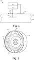
Fig. 4 is a schematic view of a dielectric barrier discharge plasma actuator as may be used in the plasma actuation system ofFig. 3 . -
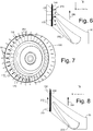
Fig. 5 a perspective view of a turbo-machinery device with a portion of the plasma actuation system ofFig. 3 . -
Fig. 6 is a schematic view of the plasma actuation system ofFig. 3 with the direction of the plasma force shown. -
Fig. 7 a perspective view of a turbo-machinery device with a portion of the plasma actuation system ofFig. 3 . -
Fig. 8 is a schematic view of the plasma actuation system ofFig. 3 with the direction of the plasma force shown. -
Fig. 9 is a schematic view of the plasma actuation system ofFig. 3 with the direction of the plasma force shown. -
Fig. 10 a perspective view of a turbo-machinery device with a portion of the plasma actuation system ofFig. 3 . - Referring now to the drawings, in which like numerals refer to like elements throughout the several views,
Fig. 1 shows a schematic view of a rotary machine such asgas turbine engine 10. Thegas turbine engine 10 may include acompressor 15. Thecompressor 15 compresses an incoming flow ofair 20. Thecompressor 15 delivers the compressed flow ofair 20 to acombustor 25. Thecombustor 25 mixes the compressed flow ofair 20 with a compressed flow offuel 30 and ignites the mixture to create a flow ofcombustion gases 35. Although only asingle combustor 25 is shown, thegas turbine engine 10 may include any number ofcombustors 25. The flow ofcombustion gases 35 is delivered in turn to aturbine 40. The flow ofcombustion gases 35 drives theturbine 40 so as to produce mechanical work. The mechanical work produced in theturbine 40 drives thecompressor 15 and also may drive anexternal load 45 such as an electrical generator and the like. - The
gas turbine engine 10 may be one of any number of different gas turbine engines offered by General Electric Company of Schenectady, New York and the like. Thegas turbine engine 10 may have other configurations and may use other types of components. Other types of gas turbine engines also may be used herein. Multiplegas turbine engines 10, other types of turbines, and other types of power generation and propulsion equipment also may be used herein together. Other types of rotary machines also may be used herein. - Generally described, the
compressor 15 and theturbine 40 include a number of circumferentially spacedblades 50 positioned on ashaft 55 for rotation therewith. Theblades 50 may be positioned within anend wall 60. Theend wall 60 may be a casing or any type of other type of structure. Atip clearance space 65 may exist between theend wall 60 and atip 70 of theblade 50. Theblades 50 may rotate while theend wall 60 is stationary. Likewise, theblade 50 may be in the form of a stationary stator and theend wall 60 may be positioned on a rotating shaft thereabout. - As is shown in
Fig. 2 , atip clearance flow 75 may be driven therethrough by a pressure difference across the blade 50 (blade loading). The interaction of theclearance flow 75 with an incomingmain flow 80 creates a region of low-speed fluid and high losses. These large clearance flow losses allow aninterface 85 to be formed therein. Theinterface 85 may be defined as a region of high entropy gradient. The low-speed fluid region enclosed by theinterface 85 thus acts as ablockage 90 to themain flow 80 and increases the blade loading near thetip 70. Increases in thisblockage 90 may be a precursor to stall events such as those described above. -
Fig. 3 shows one example of aplasma actuation system 100 as may be described herein. Theplasma actuation system 100 may be used with a turbo-machinery device 105 such as thecompressor 25 and/or theturbine 40. Theplasma actuation system 100 may include a number ofend wall actuators 110 positioned about theend wall 60. Theend wall actuators 110, in turn, may include a number of axial momentumend wall actuators 120, a number of circumferential momentumend wall actuators 130, and a number of intermediate momentumend wall actuators 135. Moreover, one or more of theblades 50 also may have a number ofblade actuators 140 positioned thereabout. The blade actuators 140 may include one or more axialmomentum blade actuators 150, one or more circumferentialmomentum blade actuators 160, and one or more intermediate momentum blade actuators. Other types ofplasma actuators 110 may be used herein in other orientations and in other locations. Not all of theactuators 110 must be used in any given application. Any number ofplasma actuators 110 may be used herein. -
Fig. 4 shows an example of dielectric barrierdischarge plasma actuator 170 as may be used as any of the actuators described above. Theactuator 170 may include a conductive or anon-conductive substrate 180. Adielectric layer 190 may be positioned thereon. A first thinconductive layer 200 may be deposited on thenon-conductive substrate 180 with thedielectric layer 190 on top. If thesubstrate 180 is conductive, the substrate itself acts as the first thinconductive layer 200. A second thinconductive layer 210 then may be disposed on thedielectric layer 190. Theconductive layers power source 220 and a wave-form controller 230. Thewave form controller 230 may be configured to control an input voltage level and pulsing, variable or AC voltage frequency, duty cycle and shape, and the like. Other types ofactuators 170 also may be used herein such as single dielectric barrier discharge actuators, surface corona discharge actuators, and the like. Other components and other configurations may be used herein. - In use, an air flow located above the
dielectric layer 190 and between theconductive layers discharge plasma 240. Theactuator 170 thus may be oriented to impart momentum to a flow therethrough via thedischarge plasma 240. In this example,multiple actuators 170 in different orientations may be used to create aswirling flow 250 from thetip clearance flow 75 and theincoming flow 80 with momentum injection as will be described in more detail below. -
Fig. 5 shows an example of the axial momentumend wall actuator 120. As is shown, theactuators 120 may be positioned about theend wall 60 and face theblades 50 about thetip clearance space 65. A number ofelectrodes 260 may be in communication with eachactuator 120. Eachactuator 120 may extend the length ofseveral blades 50.Fig. 6 shows theplasma 240 with thearrows 270 indicating the direction of the plasma force extending perpendicularly to adirection 280 of the blade rotation so as to increase the axial momentum of the flow therethrough. -
Fig. 7 shows an example of the circumferential momentumend wall actuators 130. Likewise, theactuators 130 may be positioned about theend wall 60. In this example, one ormore actuators 130 may be used for eachblade 50.Fig. 8 shows theplasma 240 with thearrows 270 indicating the direction of the plasma force running parallel and in thesame direction 280 as the blade direction.Fig. 9 shows the force of theplasma 240 running parallel but opposite of thedirection 280 of the blade rotation (counter-swirl). Either direction acts to alter the circumferential momentum of the flow therethrough. - Likewise, the intermediate momentum
end wall actuators 135 may generate theplasma 240 with force extending in any desired direction between axial and circumferential. The intermediate momentumend wall actuators 135 may alter the intermediate momentum of the flow therethrough. -
Fig. 10 shows an example of theblade actuators 140. In this example, a number of axialmomentum blade actuators 150, a number of the circumferentialmomentum blade actuators 160, and a number of intermediatemomentum blade actuators 165 may be used at thetip 70. Thearrows 270 show the different directions of the force of theplasma 240 so as to alter axial, circumferential, and/or intermediate momentum to the flow therethrough. Any number of theactuators blade 50 in any orientation. Other components and configurations also may be used herein. - The combination of the
different actuators 170 within theplasma actuation system 100 thus may be used to generate the swirling flows 250 about thetip 70 and theend wall 60 so as to reduce theblockage 90 and other losses near thetip 70. Specifically, theactuators 170 alter the axial, the circumferential momentum, and/or the intermediate momentum of the flows therethrough to create theswirling flow 250. Hence, theplasma actuation system 100 may inject an optimal combination of axial, circumferential, and/or intermediate momentum into the tip gap flows. Energizing the clearance flow by injection of momentum in optimal directions and locations thus reduces the losses and blockage introduced by the interaction of the clearance flow with the main flow. - The location of the
actuators 170 may be chosen based on a specific turbo-machinery design so as to reduce theblockage 90 and losses in and about the tip/end wall region. Theactuators 170 also may be excited at different forcing frequencies so as to minimize the losses and blockages introduced in and about the tip/end wall region. For example, the blade passing frequencies and variations thereon may be used. Theactuators 170 also have the relatively fast response time so as to enable active feedback control.Multiple actuators 170 may be used in series to augment the force imparted to theflow 250. - The appropriate injection of momentum by the
actuators 170 may energize end wall boundary layers so as to minimize end wall boundary layer separation, reduce blade loading at the tip, and minimize blockage and losses. The swirling flows 250 produced by theactuators 170 thus may improve the aerodynamic performance stability characteristics of the overall turbo-machinery device 105. Such increased stability may lead to increased safety throughout the mission, increased tolerances for stage mismatch during part speed operation and transients, and an opportunity to match stages at the compressor maximum efficiency point so as to reduce fuel bum. Moreover, theactuators 170 do not use the "expensive" compressed air from upstream stages. Reduction in tip clearance flows also may lead to reduced fuel bum, - It should be apparent that the foregoing relates only to certain embodiments of the present application and that numerous changes and modifications may be made herein by one of ordinary skill in the art without departing from the scope of the invention as defined by the following claims and the equivalents thereof.
Claims (15)
- A plasma actuation system (100) for a turbo-machinery device (105), comprising:an end wall (60);a plurality of end wall actuators (110) positioned about the end wall (60); anda blade (50) positioned adjacent to the end wall (60);wherein the plurality of end wall actuators (110) are oriented to produce a swirling flow (250) between the end wall (60) and the blade (50).
- The plasma actuation system (100) of claim 1, wherein the plurality of end wall actuators (110) comprises a plurality of circumferential momentum end wall actuators (130).
- The plasma actuation system (100) of claim 2, wherein one or more of the plurality of circumferential momentum end wall actuators (130) are positioned about the blade (50).
- The plasma actuation system (100) of any preceding claim, wherein the plurality of end wall actuators (110) comprises a plurality of intermediate momentum end wall actuators (135).
- The plasma actuation system (100) of any preceding claim, further comprising a plurality of blade actuators (140) positioned on the blade (50).
- The plasma actuation system (100) of claim 5, wherein the plurality of blade actuators (140) comprises a plurality of circumferential momentum blade actuators (160).
- The plasma actuation system (100) of either of claim 5 or 6, wherein the plurality of blade actuators (140) comprises a plurality of intermediate momentum blade actuators (165).
- The plasma actuation system (100) of any of claims 5 to 7, wherein the plurality of blade actuators (140) are positioned about a tip (70) of the blade (50).
- The plasma actuation system (100) of claim 5, wherein the plurality of end wall actuators (110) and the plurality of blade actuators (140) comprise a plurality of axial momentum actuators (120, 150).
- The plasma actuation system (100) of claim 5, wherein the plurality of end wall actuators (110) and the plurality of blade actuators (140) comprise a plurality of dielectric barrier discharge plasma actuators (170).
- The plasma actuation system (100) of claim 10, wherein each of the plurality of dielectric barrier discharge plasma actuators (170) comprises a pair of conductive layers (200, 210) to produce a plasma flow (240) therebetween.
- The plasma actuation system (100) of any preceding claim, wherein the turbo-machinery device (105) comprises a compressor (15).
- The plasma actuation system (100) of any preceding claim, wherein the turbo-machinery device (105) comprises a turbine (40).
- A method of reducing a blockage and losses (90) about an end wall (60) and a blade tip (70) of a turbo-machinery device (105), comprising:actuating a plurality of end wall actuators (110);generating circumferential and/or intermediate momentum in a flow (75, 80) therethrough; andcreating a swirling flow (250) near the end wall (60) and the blade tip (70) so as to reduce the blockage and losses (90) thereabout.
- The method of claim 14, further comprising the step of actuating a plurality of blade actuators (140) generating circumferential and/or intermediate momentum in the flow (75, 80) therethrough.
Applications Claiming Priority (1)
| Application Number | Priority Date | Filing Date | Title |
|---|---|---|---|
| US13/015,786 US20120195736A1 (en) | 2011-01-28 | 2011-01-28 | Plasma Actuation Systems to Produce Swirling Flows |
Publications (1)
| Publication Number | Publication Date |
|---|---|
| EP2481889A2 true EP2481889A2 (en) | 2012-08-01 |
Family
ID=45524412
Family Applications (1)
| Application Number | Title | Priority Date | Filing Date |
|---|---|---|---|
| EP12152500A Withdrawn EP2481889A2 (en) | 2011-01-28 | 2012-01-25 | Plasma actuation systems to produce swirling flows |
Country Status (4)
| Country | Link |
|---|---|
| US (1) | US20120195736A1 (en) |
| EP (1) | EP2481889A2 (en) |
| JP (1) | JP2012159076A (en) |
| CA (1) | CA2765666A1 (en) |
Cited By (1)
| Publication number | Priority date | Publication date | Assignee | Title |
|---|---|---|---|---|
| CN108487935A (en) * | 2018-03-15 | 2018-09-04 | 哈尔滨工业大学 | Turbine cascade leaf roof construction with array DBD plasma excitations layout |
Families Citing this family (3)
| Publication number | Priority date | Publication date | Assignee | Title |
|---|---|---|---|---|
| GB201300597D0 (en) * | 2012-10-22 | 2013-02-27 | Rolls Royce Plc | Clearance control |
| JP6881608B2 (en) * | 2017-12-21 | 2021-06-02 | 株式会社Ihi | Axial flow compressor |
| JP2021113513A (en) * | 2020-01-17 | 2021-08-05 | 三菱重工業株式会社 | Fluid controller and rotary machine |
Family Cites Families (4)
| Publication number | Priority date | Publication date | Assignee | Title |
|---|---|---|---|---|
| KR100305434B1 (en) * | 1991-10-04 | 2001-12-28 | 마에다 시게루 | Turbomachinery |
| JP3816150B2 (en) * | 1995-07-18 | 2006-08-30 | 株式会社荏原製作所 | Centrifugal fluid machinery |
| WO2003072949A1 (en) * | 2002-02-28 | 2003-09-04 | Mtu Aero Engines Gmbh | Anti-stall tip treatment means for turbo-compressors |
| US9347331B2 (en) * | 2007-06-11 | 2016-05-24 | University Of Florida Research Foundation, Inc. | Electrodynamic control of blade clearance leakage loss in turbomachinery applications |
-
2011
- 2011-01-28 US US13/015,786 patent/US20120195736A1/en not_active Abandoned
-
2012
- 2012-01-24 JP JP2012011592A patent/JP2012159076A/en active Pending
- 2012-01-25 EP EP12152500A patent/EP2481889A2/en not_active Withdrawn
- 2012-01-26 CA CA2765666A patent/CA2765666A1/en not_active Abandoned
Non-Patent Citations (1)
| Title |
|---|
| None |
Cited By (1)
| Publication number | Priority date | Publication date | Assignee | Title |
|---|---|---|---|---|
| CN108487935A (en) * | 2018-03-15 | 2018-09-04 | 哈尔滨工业大学 | Turbine cascade leaf roof construction with array DBD plasma excitations layout |
Also Published As
| Publication number | Publication date |
|---|---|
| CA2765666A1 (en) | 2012-07-28 |
| JP2012159076A (en) | 2012-08-23 |
| US20120195736A1 (en) | 2012-08-02 |
Similar Documents
| Publication | Publication Date | Title |
|---|---|---|
| JP5550563B2 (en) | How to operate a compressor | |
| CN105339597B (en) | Turbofan engine with generator | |
| US9638050B2 (en) | Axial compressor, gas turbine with axial compressor, and its remodeling method | |
| EP3159573B1 (en) | Torsional damping for gas turbine engines | |
| US20160160867A1 (en) | Electrically coupled counter-rotation for gas turbine compressors | |
| EP2128388A2 (en) | Diffuser | |
| JP2011508148A (en) | Compressor tip clearance control system including plasma actuator, compressor, and gas turbine engine including the control system | |
| CN103459774A (en) | Compressor airfoil with tip dihedral | |
| JP2011508149A (en) | Plasma compressor | |
| US20130170977A1 (en) | Gas Turbine Nozzle with a Flow Groove | |
| US11002141B2 (en) | Method and system for leading edge auxiliary turbine vanes | |
| EP2613014A2 (en) | Stage of a gas turbine engine and corresponding method of retrofitting | |
| EP2971581B1 (en) | Active seal system and method of operating a turbomachine | |
| CN104131845A (en) | Axial turbomachine stator with ailerons at the blade roots | |
| US20180335051A1 (en) | Method and system for leading edge auxiliary vanes | |
| EP2386014A1 (en) | Plasma enhanced booster and method of operation | |
| US10221720B2 (en) | Structural frame integrated with variable-vectoring flow control for use in turbine systems | |
| US9181900B1 (en) | Fully advanced superconducting segmented turbo-electric rotormachine (fasster) | |
| WO2015126489A2 (en) | Exhaust section for an aircraft gas turbine engine | |
| CN103184897A (en) | Gas turbine nozzle with a flow fence | |
| CN112928935A (en) | Electrical system | |
| EP2481889A2 (en) | Plasma actuation systems to produce swirling flows | |
| CN105986903B (en) | Power generation system with compressor and turbo expander producing excess air flow | |
| EP3070290A1 (en) | Power generation system having compressor creating excess air flow and turbo-expander to increase turbine exhaust gas mass flow | |
| EP2613013B1 (en) | Stage and turbine of a gas turbine engine |
Legal Events
| Date | Code | Title | Description |
|---|---|---|---|
| PUAI | Public reference made under article 153(3) epc to a published international application that has entered the european phase |
Free format text: ORIGINAL CODE: 0009012 |
|
| AK | Designated contracting states |
Kind code of ref document: A2 Designated state(s): AL AT BE BG CH CY CZ DE DK EE ES FI FR GB GR HR HU IE IS IT LI LT LU LV MC MK MT NL NO PL PT RO RS SE SI SK SM TR |
|
| AX | Request for extension of the european patent |
Extension state: BA ME |
|
| STAA | Information on the status of an ep patent application or granted ep patent |
Free format text: STATUS: THE APPLICATION IS DEEMED TO BE WITHDRAWN |
|
| 18D | Application deemed to be withdrawn |
Effective date: 20150801 |