EP2481669A2 - Attenuation of open rotor noise - Google Patents
Attenuation of open rotor noise Download PDFInfo
- Publication number
- EP2481669A2 EP2481669A2 EP12151061A EP12151061A EP2481669A2 EP 2481669 A2 EP2481669 A2 EP 2481669A2 EP 12151061 A EP12151061 A EP 12151061A EP 12151061 A EP12151061 A EP 12151061A EP 2481669 A2 EP2481669 A2 EP 2481669A2
- Authority
- EP
- European Patent Office
- Prior art keywords
- aeronautical
- nacelle
- engine
- centerbody
- propulsor
- Prior art date
- Legal status (The legal status is an assumption and is not a legal conclusion. Google has not performed a legal analysis and makes no representation as to the accuracy of the status listed.)
- Granted
Links
- 230000003993 interaction Effects 0.000 claims description 10
- 230000001413 cellular effect Effects 0.000 claims description 2
- 238000004458 analytical method Methods 0.000 description 6
- 230000000694 effects Effects 0.000 description 6
- 230000009467 reduction Effects 0.000 description 4
- 238000001228 spectrum Methods 0.000 description 4
- 238000002485 combustion reaction Methods 0.000 description 3
- 230000014509 gene expression Effects 0.000 description 3
- 230000008859 change Effects 0.000 description 2
- 230000001141 propulsive effect Effects 0.000 description 2
- 238000003491 array Methods 0.000 description 1
- 230000008901 benefit Effects 0.000 description 1
- 230000006835 compression Effects 0.000 description 1
- 238000007906 compression Methods 0.000 description 1
- 239000000446 fuel Substances 0.000 description 1
- 239000000203 mixture Substances 0.000 description 1
- 238000012986 modification Methods 0.000 description 1
- 230000004048 modification Effects 0.000 description 1
- 230000001902 propagating effect Effects 0.000 description 1
Images


Classifications
-
- B—PERFORMING OPERATIONS; TRANSPORTING
- B64—AIRCRAFT; AVIATION; COSMONAUTICS
- B64C—AEROPLANES; HELICOPTERS
- B64C7/00—Structures or fairings not otherwise provided for
- B64C7/02—Nacelles
-
- B—PERFORMING OPERATIONS; TRANSPORTING
- B64—AIRCRAFT; AVIATION; COSMONAUTICS
- B64C—AEROPLANES; HELICOPTERS
- B64C11/00—Propellers, e.g. of ducted type; Features common to propellers and rotors for rotorcraft
- B64C11/46—Arrangements of, or constructional features peculiar to, multiple propellers
- B64C11/48—Units of two or more coaxial propellers
-
- B—PERFORMING OPERATIONS; TRANSPORTING
- B64—AIRCRAFT; AVIATION; COSMONAUTICS
- B64D—EQUIPMENT FOR FITTING IN OR TO AIRCRAFT; FLIGHT SUITS; PARACHUTES; ARRANGEMENT OR MOUNTING OF POWER PLANTS OR PROPULSION TRANSMISSIONS IN AIRCRAFT
- B64D29/00—Power-plant nacelles, fairings or cowlings
-
- B—PERFORMING OPERATIONS; TRANSPORTING
- B64—AIRCRAFT; AVIATION; COSMONAUTICS
- B64C—AEROPLANES; HELICOPTERS
- B64C2230/00—Boundary layer controls
- B64C2230/14—Boundary layer controls achieving noise reductions
-
- B—PERFORMING OPERATIONS; TRANSPORTING
- B64—AIRCRAFT; AVIATION; COSMONAUTICS
- B64D—EQUIPMENT FOR FITTING IN OR TO AIRCRAFT; FLIGHT SUITS; PARACHUTES; ARRANGEMENT OR MOUNTING OF POWER PLANTS OR PROPULSION TRANSMISSIONS IN AIRCRAFT
- B64D27/00—Arrangement or mounting of power plants in aircraft; Aircraft characterised by the type or position of power plants
- B64D2027/005—Aircraft with an unducted turbofan comprising contra-rotating rotors, e.g. contra-rotating open rotors [CROR]
-
- Y—GENERAL TAGGING OF NEW TECHNOLOGICAL DEVELOPMENTS; GENERAL TAGGING OF CROSS-SECTIONAL TECHNOLOGIES SPANNING OVER SEVERAL SECTIONS OF THE IPC; TECHNICAL SUBJECTS COVERED BY FORMER USPC CROSS-REFERENCE ART COLLECTIONS [XRACs] AND DIGESTS
- Y02—TECHNOLOGIES OR APPLICATIONS FOR MITIGATION OR ADAPTATION AGAINST CLIMATE CHANGE
- Y02T—CLIMATE CHANGE MITIGATION TECHNOLOGIES RELATED TO TRANSPORTATION
- Y02T50/00—Aeronautics or air transport
- Y02T50/10—Drag reduction
-
- Y—GENERAL TAGGING OF NEW TECHNOLOGICAL DEVELOPMENTS; GENERAL TAGGING OF CROSS-SECTIONAL TECHNOLOGIES SPANNING OVER SEVERAL SECTIONS OF THE IPC; TECHNICAL SUBJECTS COVERED BY FORMER USPC CROSS-REFERENCE ART COLLECTIONS [XRACs] AND DIGESTS
- Y02—TECHNOLOGIES OR APPLICATIONS FOR MITIGATION OR ADAPTATION AGAINST CLIMATE CHANGE
- Y02T—CLIMATE CHANGE MITIGATION TECHNOLOGIES RELATED TO TRANSPORTATION
- Y02T50/00—Aeronautics or air transport
- Y02T50/60—Efficient propulsion technologies, e.g. for aircraft
Definitions
- the present invention relates to the attenuation of open rotor noise produced by an aeronautical propulsor.
- a twin-spooled, contra-rotating propeller, gas turbine engine is generally indicated at 10 and has a principal and rotational axis 9.
- the engine 10 comprises a core engine 11 having, in axial flow series, an air intake 12, an intermediate pressure compressor 14 (IPC), a high-pressure compressor 15 (HPC), combustion equipment 16, a high-pressure turbine 17 (HPT), low pressure turbine 18 (LPT), a free power turbine 19 (LPT) and a core exhaust nozzle 20.
- a nacelle 21 generally surrounds the core engine 11 and defines the intake 12 and nozzle 20 and a core exhaust duct 22.
- the engine 10 also comprises two contra-rotating, unshrouded propellers (i.e. open rotors) 23, 24 attached to and driven by the free power turbine 19, which comprises contra-rotating blade arrays 25, 26.
- the gas turbine engine 10 works in a conventional manner so that air entering the intake 12 is accelerated and compressed by the IPC 14 and directed into the HPC 15 where further compression takes place.
- the compressed air exhausted from the HPC 15 is directed into the combustion equipment 16 where it is mixed with fuel and the mixture combusted.
- the resultant hot combustion products then expand through, and thereby drive the high, low-pressure and free power turbines 17, 18, 19 before being exhausted through the nozzle 20 to provide some propulsive thrust.
- the high, low-pressure and free power turbines 17, 18, 19 respectively drive the high and intermediate pressure compressors 15, 14 and the open rotors 23, 24 by suitable interconnecting shafts.
- the open rotors 23, 24 normally provide the majority of the propulsive thrust.
- the engine shown in Figure 1 is one form of an open rotor aeronautical propulsor.
- Other forms include tractor engines, in which the open rotors are located forward of the core engine.
- a problem associated with such propulsors is noise produced by the open rotors.
- the fan which produces much of the thrust is contained in a duct.
- This duct provides an opportunity to attenuate sound radiating from the fan.
- the duct can be lined with acoustic panels.
- the open rotor propulsor there is no such surrounding duct.
- An aim of the present invention is to reduce the level of noise produced by an aeronautical propulsor having one or more open rotors.
- the present invention is at least partly based on the realisation that propeller noise reflected off the engine nacelle can be a significant contributor to the noise level.
- the present invention provides an aeronautical propulsor having:
- the acoustic treatment can significantly reduce the level of "interaction tones" which are produced by the interaction of an open rotor with the unsteady flow field produced by an adjacent contra-rotating open rotor, or by a steady distortion such as pylon wake or engine exhaust.
- the propulsor may have any one or, to the extent that they are compatible, any combination of the following optional features.
- the core engine is a gas turbine engine.
- the propulsor may have a single open rotor (i.e. a single propeller), but more typically has contra-rotating open rotors.
- the external surface of the nacelle adjacent the propellers is acoustically treated, these parts of the nacelle generally receiving the highest levels of incident open rotor noise.
- the acoustic treatment typically comprises one or more acoustic panels which form the exterior surface of the nacelle.
- the or each acoustic panel may comprise a perforated outer layer covering a cellular or fibrous inner layer, such structure being effective at dissipating sound energy into heat.
- other types of acoustic panel known to the skilled person may suitably be used.
- the acoustic treatment provides a reflection coefficient of at most 60%, and more preferably of at most 50% or 40%, over an appropriate range of angles of incidence and frequencies. For example, it is typically desirable to reduce the interaction tones which make the largest contribution to the total sound power (e.g. at far-field) produced by the open rotor. Further, reducing the reflection coefficient for a normal angle of incidence tends to be a productive approach for reducing the total sound power.
- the acoustic treatment may provide a reflection coefficient of at most 60%, and more preferably of at most 50% or 40%, for a normal angle of incidence at the frequency of the interaction tone for the open rotors which makes the largest contribution to the far-field, total sound power level.
- the application of a suitable acoustic treatment to the exterior nacelle surface can substantially reduce the level of the scattered field.
- the effectiveness of such a treatment is demonstrated by the following analysis.
- B corresponds to the number of propeller blades
- a centerbody i.e. engine nacelle
- a centerbody is modelled by a cylinder of radius b (m) having an infinite axial extent and a finite (dimensionless) surface impedance z ⁇ .
- An observer is located a distance
- from the centre of rotation of the rotor, at azimuthal angle ⁇ 0 and polar angle ⁇ , the polar angle being the angle measured between a line connecting the observer with the origin and the engine axis x ( ⁇ 0° along the positive x -axis).
- Glegg ibid
- rotor alone tones which are associated with the steady loading and finite thickness of the propeller blades, are not significantly affected by centerbody scattering.
- ⁇ azimuthal angle
- the acoustic treatment (comprising e.g. acoustic panels) can be tuned to reduce the interaction tones which make the largest contribution to the total sound power, e.g. at far-field. Further, providing an acoustic treatment which reduces the reflection coefficient at a normal angle of incidence tends to be effective at reducing the total sound power.
- a rigid centrebody i.e. engine nacelle
- engine nacelle has a significant effect on "interaction tones" produced by the interaction of an open rotor with the wake or potential field of an adjacent pylon, engine exhaust or open rotor.
- interaction tones are believed to be significant sources of noise from an open rotor. Therefore, acoustically treating the exterior surface of the centrebody (e.g. by the provision of acoustic panels) can reduce the scattered part of the sound field, and thereby significantly reduce the total radiated sound field.
- the acoustic treatment may additionally produce small, but useful, reductions in rotor alone tones and broadband noise levels.
Landscapes
- Engineering & Computer Science (AREA)
- Aviation & Aerospace Engineering (AREA)
- Wind Motors (AREA)
- Soundproofing, Sound Blocking, And Sound Damping (AREA)
- Lubrication Of Internal Combustion Engines (AREA)
Abstract
Description
- The present invention relates to the attenuation of open rotor noise produced by an aeronautical propulsor.
- Referring to
Figure 1 , a twin-spooled, contra-rotating propeller, gas turbine engine is generally indicated at 10 and has a principal and rotational axis 9. Theengine 10 comprises acore engine 11 having, in axial flow series, anair intake 12, an intermediate pressure compressor 14 (IPC), a high-pressure compressor 15 (HPC),combustion equipment 16, a high-pressure turbine 17 (HPT), low pressure turbine 18 (LPT), a free power turbine 19 (LPT) and acore exhaust nozzle 20. Anacelle 21 generally surrounds thecore engine 11 and defines theintake 12 andnozzle 20 and acore exhaust duct 22. Theengine 10 also comprises two contra-rotating, unshrouded propellers (i.e. open rotors) 23, 24 attached to and driven by thefree power turbine 19, which comprises contra-rotatingblade arrays - The
gas turbine engine 10 works in a conventional manner so that air entering theintake 12 is accelerated and compressed by the IPC 14 and directed into the HPC 15 where further compression takes place. The compressed air exhausted from the HPC 15 is directed into thecombustion equipment 16 where it is mixed with fuel and the mixture combusted. The resultant hot combustion products then expand through, and thereby drive the high, low-pressure andfree power turbines nozzle 20 to provide some propulsive thrust. The high, low-pressure andfree power turbines intermediate pressure compressors open rotors open rotors - The engine shown in
Figure 1 is one form of an open rotor aeronautical propulsor. Other forms include tractor engines, in which the open rotors are located forward of the core engine. - A problem associated with such propulsors is noise produced by the open rotors. In a high-bypass turbofan engine, the fan which produces much of the thrust is contained in a duct. This duct provides an opportunity to attenuate sound radiating from the fan. For example, the duct can be lined with acoustic panels. However, for the open rotor propulsor, there is no such surrounding duct.
- An aim of the present invention is to reduce the level of noise produced by an aeronautical propulsor having one or more open rotors. The present invention is at least partly based on the realisation that propeller noise reflected off the engine nacelle can be a significant contributor to the noise level.
- Accordingly, the present invention provides an aeronautical propulsor having:
- a core engine,
- one or more open rotors driven by the engine, and
- a nacelle which encloses the core engine and provides an aerodynamic external surface;
- The acoustic treatment can significantly reduce the level of "interaction tones" which are produced by the interaction of an open rotor with the unsteady flow field produced by an adjacent contra-rotating open rotor, or by a steady distortion such as pylon wake or engine exhaust.
- The propulsor may have any one or, to the extent that they are compatible, any combination of the following optional features.
- Typically, the core engine is a gas turbine engine.
- The propulsor may have a single open rotor (i.e. a single propeller), but more typically has contra-rotating open rotors.
- Preferably, the external surface of the nacelle adjacent the propellers is acoustically treated, these parts of the nacelle generally receiving the highest levels of incident open rotor noise.
- The acoustic treatment typically comprises one or more acoustic panels which form the exterior surface of the nacelle. For example, the or each acoustic panel may comprise a perforated outer layer covering a cellular or fibrous inner layer, such structure being effective at dissipating sound energy into heat. However, other types of acoustic panel known to the skilled person may suitably be used.
- Preferably, the acoustic treatment provides a reflection coefficient of at most 60%, and more preferably of at most 50% or 40%, over an appropriate range of angles of incidence and frequencies. For example, it is typically desirable to reduce the interaction tones which make the largest contribution to the total sound power (e.g. at far-field) produced by the open rotor. Further, reducing the reflection coefficient for a normal angle of incidence tends to be a productive approach for reducing the total sound power. Thus the acoustic treatment may provide a reflection coefficient of at most 60%, and more preferably of at most 50% or 40%, for a normal angle of incidence at the frequency of the interaction tone for the open rotors which makes the largest contribution to the far-field, total sound power level.
- Embodiments of the invention will now be described by way of example with reference to the accompanying drawings in which:
-
Figure 1 shows a schematic longitudinal cross-section through a twin-spooled, contra-rotating propeller, gas turbine engine; -
Figure 2 shows a model of a point force rotating around a centerbody of infinite axial extent; -
Figure 3 is a plot of variation of axial loading with azimuthal angle; -
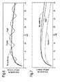
Figure 4 shows three plots of far-field sound pressure against time for an observer located on the same side of the centerbody as an impulsive force, the three plots being for an acoustically treated centerbody, a rigid centerbody, and no scattering from the centerbody; -
Figure 5 shows three plots of far-field sound pressure against time for an observer located on the opposite side of the centerbody as an impulsive force, the three plots being for an acoustically treated centerbody, a rigid centerbody, and no scattering from the centerbody; -
Figure 6 shows three acoustic spectra plots of tone amplitude against mB for the three plots ofFigure 4 ; and -
Figure 7 shows three acoustic spectra plots of tone amplitude against mB for the three plots ofFigure 5 . - S. A. L. Glegg (1991) Effect of Centerbody Scattering on Propeller Noise, AIAA Journal vol. 29, pp. 572-576 has shown that specific tones, which are peculiar to open rotors operating in a nonuniform flow-field, are affected by scattering from the nacelle. This scattering has a significant effect on radiated noise levels.
- However, according to the present invention, the application of a suitable acoustic treatment to the exterior nacelle surface can substantially reduce the level of the scattered field. The effectiveness of such a treatment is demonstrated by the following analysis.
- As shown schematically in
Figure 2 , a propeller is modelled as B (where B corresponds to the number of propeller blades) evenly spaced point forces which rotate with angular velocity Ω (rad/s) in a circle of radius a (m), at x = 0. The effects of forward motion are not included. A centerbody (i.e. engine nacelle) is modelled by a cylinder of radius b (m) having an infinite axial extent and a finite (dimensionless) surface impedance z̃. An observer is located a distance |x 0| from the centre of rotation of the rotor, at azimuthal angle ϕ0 and polar angle θ, the polar angle being the angle measured between a line connecting the observer with the origin and the engine axis x (θ = 0° along the positive x-axis). Although simplifications are used in the calculation given below, the analysis is sufficient to demonstrate the effectiveness of acoustically treating the centerbody. The calculation could readily be extended to include effects of forward motion and distributed loading over the blade surfaces. - Each blade is represented by a point force which is assumed to have a thrust component L which acts parallel to the centerbody axis at x = 0, r = a. Glegg (ibid) has shown that rotor alone tones, which are associated with the steady loading and finite thickness of the propeller blades, are not significantly affected by centerbody scattering. However, for open rotor engines a significant level of noise is produced when the loading on the propeller blades varies rapidly with azimuthal angle ϕ. This type of unsteady loading occurs when a blade passes through the wake or potential field of the adjacent propeller or a pylon. This unsteady loading can be the main source of aeroacoustic noise produced by an open rotor engine at take-off and approach. The analysis presented considers an "impulsive" force which has a maximum amplitude at ϕ = 0° and is similar to the loading which would be produced by a blade passing through a rectilinear vortex located at ϕ = 0° and r = a. The loading is described by the function L = ϕ s 2/(ϕ s 2 + ϕ2), where ϕ s = 3.75°. The variation in amplitude of L is shown in
Figure 3 . - Following the analysis of Glegg (ibid), but applying a finite impedance boundary condition on the surface of the cylinder (rather than the rigid boundary condition which Glegg considered) an expression for the far-field sound pressure, p(x 0 , t), due to the rotating point force, L , can be derived. For completeness this expression is given below.


- The expressions given above are used to generate far-field sound pressure plots which are shown in
Figures 4 and 5 for respectively an observer location on the same side of the centerbody as the impulsive force (i.e. ϕ0 = 0°) and a location on the opposite side of the centerbody as the impulsive force (i.e. ϕ0 = 180°). The plots ofFigures 4 and 5 are for a one-bladed propeller with b/a = 0.3, θ = 45° and source Mach number 0.7. In each ofFigures 4 and 5 plots of sound pressure as a function time are given for three different cases. The first case assumes an acoustically treated centerbody with surface impedance z̃ = 1+0.1i. The second case assumes a rigid (i.e. untreated) centerbody. The third case assumes no scattering from the centerbody. - Considering
Figure 4 (observer location on the same side of the centerbody as the impulsive force), all three predictions show an almost identical acoustic pulse at about 0.2 s associated with a direct wave propagating from the impulsive force. The rigid and lined centerbody predictions then show secondary acoustic pulses associated with reflections from the centerbody. The amplitude of the reflected pulse from the acoustically treated centerbody is substantially weaker than that from the rigid centerbody. - Turning then to
Figure 5 (observer location on the opposite side of the centerbody as the impulsive force), relative to the no scattering prediction, the rigid centerbody shows a slight reduction in the amplitude of the acoustic pulse. This is presumably due to the "shielding" provided by the centerbody. For the case with the acoustically treated centerbody there is a substantial reduction in the amplitude of the pulse. - The corresponding acoustic spectra for the acoustically treated, rigid and no scattering cases are also plotted in
Figures 6 and 7 as tone amplitude against mB (i.e. tone number x number of blades). When the observer is located on the same side of the cylinder as the impulsive force (Figure 6 ), the rigid centerbody appears to substantially change the sound pressure spectrum relative to the no scattering prediction, while the acoustically treated centerbody appears to produce only a relatively small change. However, it should be born in mind that there is only a relatively small reflected acoustic pulse at this observer position. For the case of an observer on the opposite side of the centerbody (Figure 7 ), the rigid centerbody has little effect on the amplitude of the low frequency acoustic harmonics relative to the no scattering prediction, although higher harmonics are reduced by approximately 4dB. In contrast, there is a significant reduction in the tone amplitude for the acoustically treated case. - The above analysis uses a point force model to demonstrate the benefit of acoustically treating the centrebody to reduce the level of noise caused by interactions tones. It would be straightforward for the skilled person to extend the analysis to a full open rotor model.
- With a more elaborate model, and indeed with experimental testing, it can be possible to specify desirable characteristics of the acoustic treatment. For example, the acoustic treatment (comprising e.g. acoustic panels) can be tuned to reduce the interaction tones which make the largest contribution to the total sound power, e.g. at far-field. Further, providing an acoustic treatment which reduces the reflection coefficient at a normal angle of incidence tends to be effective at reducing the total sound power.
- In summary, a rigid centrebody (i.e. engine nacelle) has a significant effect on "interaction tones" produced by the interaction of an open rotor with the wake or potential field of an adjacent pylon, engine exhaust or open rotor. These interaction tones are believed to be significant sources of noise from an open rotor. Therefore, acoustically treating the exterior surface of the centrebody (e.g. by the provision of acoustic panels) can reduce the scattered part of the sound field, and thereby significantly reduce the total radiated sound field. The acoustic treatment may additionally produce small, but useful, reductions in rotor alone tones and broadband noise levels.
- While the invention has been described in conjunction with the exemplary embodiments described above, many equivalent modifications and variations will be apparent to those skilled in the art when given this disclosure. Accordingly, the exemplary embodiments of the invention set forth above are considered to be illustrative and not limiting. Various changes to the described embodiments may be made without departing from the spirit and scope of the invention.
- All references referred to above are hereby incorporated by reference.
Claims (7)
- An aeronautical propulsor having:a core engine (11),one or more open rotors (23, 24) driven by the engine, anda nacelle (21) which encloses the core engine and provides an aerodynamic external surface;wherein at least a portion of the external surface of the nacelle is acoustically treated to attenuate noise produced by the open rotors.
- An aeronautical propulsor according to claim 1, wherein the external surface of the nacelle adjacent the open rotors is acoustically treated.
- An aeronautical propulsor according to claim 1 or 2, wherein the acoustic treatment comprises one or more acoustic panels which form the exterior surface of the nacelle.
- An aeronautical propulsor according to claim 3, wherein the or each acoustic panel comprises a perforated outer layer covering a cellular or fibrous inner layer.
- An aeronautical propulsor according to any one of the previous claims, wherein the acoustic treatment provides a reflection coefficient of at most 60% for a normal angle of incidence at the frequency of the interaction tone for the open rotors which makes the largest contribution to the far-field, total sound power.
- An aeronautical propulsor according to any one of the previous claims, wherein the core engine is a gas turbine engine.
- An aeronautical propulsor according to any one of the previous claims having contra-rotating open rotors.
Applications Claiming Priority (1)
| Application Number | Priority Date | Filing Date | Title |
|---|---|---|---|
| GBGB1101609.4A GB201101609D0 (en) | 2011-01-31 | 2011-01-31 | Attenuation of open rotor noise |
Publications (3)
| Publication Number | Publication Date |
|---|---|
| EP2481669A2 true EP2481669A2 (en) | 2012-08-01 |
| EP2481669A3 EP2481669A3 (en) | 2013-03-27 |
| EP2481669B1 EP2481669B1 (en) | 2017-05-17 |
Family
ID=43824838
Family Applications (1)
| Application Number | Title | Priority Date | Filing Date |
|---|---|---|---|
| EP12151061.4A Active EP2481669B1 (en) | 2011-01-31 | 2012-01-13 | Attenuation of open rotor noise |
Country Status (3)
| Country | Link |
|---|---|
| US (1) | US20120195739A1 (en) |
| EP (1) | EP2481669B1 (en) |
| GB (1) | GB201101609D0 (en) |
Families Citing this family (18)
| Publication number | Priority date | Publication date | Assignee | Title |
|---|---|---|---|---|
| FR3006998B1 (en) * | 2013-06-18 | 2015-06-05 | Snecma | VENTILATION OF A TURBOMACHINE NACELLE |
| GB201404938D0 (en) * | 2014-03-19 | 2014-04-30 | Rolls Royce Plc | Fluidfoil fence |
| US9630702B2 (en) | 2015-06-30 | 2017-04-25 | Rohr, Inc. | Noise attenuation for an open rotor aircraft propulsion system |
| US10723440B2 (en) * | 2016-03-23 | 2020-07-28 | Amazon Technologies, Inc. | Aerial vehicle with different propeller blade configurations |
| US11305874B2 (en) | 2016-03-23 | 2022-04-19 | Amazon Technologies, Inc. | Aerial vehicle adaptable propeller blades |
| US10583914B2 (en) | 2016-03-23 | 2020-03-10 | Amazon Technologies, Inc. | Telescoping propeller blades for aerial vehicles |
| US10526070B2 (en) | 2016-03-23 | 2020-01-07 | Amazon Technologies, Inc. | Aerial vehicle propulsion mechanism with coaxially aligned propellers |
| US10399666B2 (en) | 2016-03-23 | 2019-09-03 | Amazon Technologies, Inc. | Aerial vehicle propulsion mechanism with coaxially aligned and independently rotatable propellers |
| US11834196B2 (en) | 2019-10-15 | 2023-12-05 | General Electric Company | System and method for control for unducted engine |
| US11286795B2 (en) | 2019-10-15 | 2022-03-29 | General Electric Company | Mount for an airfoil |
| US12103702B2 (en) | 2019-10-15 | 2024-10-01 | General Electric Company | Removeable fuselage shield for an aircraft |
| US11506067B2 (en) | 2019-10-15 | 2022-11-22 | General Electric Company | Gas turbine engine with clutch assembly |
| US11401824B2 (en) | 2019-10-15 | 2022-08-02 | General Electric Company | Gas turbine engine outlet guide vane assembly |
| US12410758B2 (en) | 2022-01-10 | 2025-09-09 | General Electric Company | Three-stream gas turbine engine control |
| US12275532B2 (en) | 2022-08-15 | 2025-04-15 | General Electric Company | Gas turbine engine noise reduction |
| US12480449B2 (en) | 2022-08-22 | 2025-11-25 | General Electric Company | Propulsion system including an electric machine for starting a gas turbine engine |
| US12352181B2 (en) | 2023-01-30 | 2025-07-08 | General Electric Company | Turbine airfoils |
| US20240425190A1 (en) * | 2023-06-23 | 2024-12-26 | Raytheon Technologies Corporation | Method to decrease acoustic signature of a hybrid electric propulsion system |
Family Cites Families (13)
| Publication number | Priority date | Publication date | Assignee | Title |
|---|---|---|---|---|
| US2918984A (en) * | 1953-10-08 | 1959-12-29 | Koppers Co Inc | Sound control shroud for aircraft engines |
| US3439774A (en) * | 1966-01-21 | 1969-04-22 | Boeing Co | Sound energy absorbing apparatus |
| US4863352A (en) * | 1984-11-02 | 1989-09-05 | General Electric Company | Blade carrying means |
| DE8713745U1 (en) * | 1987-10-13 | 1988-03-10 | Kastens, Karl, Dipl.-Ing., 2742 Gnarrenburg | Propeller blower |
| US5054998A (en) * | 1988-09-30 | 1991-10-08 | The Boeing Company, Inc. | Thrust reversing system for counter rotating propellers |
| US5702231A (en) * | 1996-08-09 | 1997-12-30 | The Boeing Company | Apparatus and method for reducing noise emissions from a gas turbine engine inlet |
| GB0016149D0 (en) * | 2000-06-30 | 2000-08-23 | Short Brothers Plc | A noise attenuation panel |
| US7540354B2 (en) * | 2006-05-26 | 2009-06-02 | United Technologies Corporation | Micro-perforated acoustic liner |
| FR2905734B1 (en) * | 2006-09-07 | 2012-07-13 | Airbus France | DEVICE FOR ENHANCING THE EFFICIENCY OF ACOUSTIC TREATMENTS IN A CONDUIT OF AN AIRCRAFT ENGINE |
| GB0617769D0 (en) * | 2006-09-09 | 2006-10-18 | Rolls Royce Plc | An engine |
| FR2909974B1 (en) * | 2006-12-13 | 2009-02-06 | Aircelle Sa | NACELLE FOR TURBOJET DOUBLE FLOW |
| JP2009062977A (en) * | 2007-08-15 | 2009-03-26 | Rohr Inc | Linear acoustic liner |
| US8210798B2 (en) * | 2008-02-13 | 2012-07-03 | United Technologies Corporation | Cooled pusher propeller system |
-
2011
- 2011-01-31 GB GBGB1101609.4A patent/GB201101609D0/en not_active Ceased
-
2012
- 2012-01-13 US US13/350,005 patent/US20120195739A1/en not_active Abandoned
- 2012-01-13 EP EP12151061.4A patent/EP2481669B1/en active Active
Non-Patent Citations (1)
| Title |
|---|
| S. A. L. GLEGG: "Effect of Centerbody Scattering on Propeller Noise", AIAA JOURNAL, vol. 29, 1991, pages 572 - 576 |
Also Published As
| Publication number | Publication date |
|---|---|
| EP2481669B1 (en) | 2017-05-17 |
| GB201101609D0 (en) | 2011-03-16 |
| US20120195739A1 (en) | 2012-08-02 |
| EP2481669A3 (en) | 2013-03-27 |
Similar Documents
| Publication | Publication Date | Title |
|---|---|---|
| EP2481669B1 (en) | Attenuation of open rotor noise | |
| JP4718815B2 (en) | Method and system for reducing jet engine noise | |
| Neise et al. | Technology approach to aero engine noise reduction | |
| JP2016501761A (en) | Unducted thrust generation system architecture | |
| Delattre et al. | Influence of torque ratio on counter-rotating open-rotor interaction noise | |
| Azimi et al. | Using acoustic liner for fan noise reduction in modern turbofan engines | |
| Yu et al. | Quiet technology demonstrator 2 intake liner design and validation | |
| Martens et al. | Jet noise reduction for high speed exhaust systems | |
| Oleson et al. | Small aircraft propeller noise with ducted propeller | |
| Kuznetsov | Noise control problems of passenger airplanes (a review) | |
| Miljković et al. | Two vs. three blade propeller-cockpit noise comparison | |
| US10894594B2 (en) | Aircraft including a wing with improved acoustic treatment | |
| Stephens et al. | Acoustic shielding for a model scale counter-rotation open rotor | |
| Ishii et al. | Noise test of revised notched nozzle using a jet engine | |
| Gorj-Bandpy et al. | Passive techniques for fan noise reduction in new turbofan engines | |
| Quaroni et al. | Mitigation strategies for acoustic reflections generated by an axisymmetric wind tunnel nozzle | |
| Samokhin et al. | Study of the contra-rotating open rotor noise under static conditions | |
| Lewy | Semi-empirical prediction of tone noise due to counter-rotating open rotors | |
| Lewy | Prediction of turbofan rotor or stator broadband noise radiation | |
| Woodward et al. | Fan noise reduction with increased bypass nozzle area | |
| Ishii et al. | Experimental Study on Acoustic Performances of Notched Nozzle Using a Subscale Turbofan Engine | |
| Loeffler et al. | Acoustic design of the QCSEE propulsion systems | |
| Huff et al. | Jet engine noise generation, prediction and control | |
| Parry et al. | Aeroacoustic tests of isolated open rotors at high speed | |
| Atvars et al. | The development of inflow control devices for improved simulation offlight noise levels during static testing of a HBPR turbofan engine |
Legal Events
| Date | Code | Title | Description |
|---|---|---|---|
| PUAI | Public reference made under article 153(3) epc to a published international application that has entered the european phase |
Free format text: ORIGINAL CODE: 0009012 |
|
| AK | Designated contracting states |
Kind code of ref document: A2 Designated state(s): AL AT BE BG CH CY CZ DE DK EE ES FI FR GB GR HR HU IE IS IT LI LT LU LV MC MK MT NL NO PL PT RO RS SE SI SK SM TR |
|
| AX | Request for extension of the european patent |
Extension state: BA ME |
|
| PUAL | Search report despatched |
Free format text: ORIGINAL CODE: 0009013 |
|
| AK | Designated contracting states |
Kind code of ref document: A3 Designated state(s): AL AT BE BG CH CY CZ DE DK EE ES FI FR GB GR HR HU IE IS IT LI LT LU LV MC MK MT NL NO PL PT RO RS SE SI SK SM TR |
|
| AX | Request for extension of the european patent |
Extension state: BA ME |
|
| RIC1 | Information provided on ipc code assigned before grant |
Ipc: B64C 11/48 20060101ALI20130221BHEP Ipc: B64C 7/02 20060101AFI20130221BHEP Ipc: B64D 29/00 20060101ALI20130221BHEP |
|
| 17P | Request for examination filed |
Effective date: 20130828 |
|
| RBV | Designated contracting states (corrected) |
Designated state(s): AL AT BE BG CH CY CZ DE DK EE ES FI FR GB GR HR HU IE IS IT LI LT LU LV MC MK MT NL NO PL PT RO RS SE SI SK SM TR |
|
| RAP1 | Party data changed (applicant data changed or rights of an application transferred) |
Owner name: ROLLS-ROYCE PLC |
|
| 17Q | First examination report despatched |
Effective date: 20151117 |
|
| GRAP | Despatch of communication of intention to grant a patent |
Free format text: ORIGINAL CODE: EPIDOSNIGR1 |
|
| STAA | Information on the status of an ep patent application or granted ep patent |
Free format text: STATUS: GRANT OF PATENT IS INTENDED |
|
| INTG | Intention to grant announced |
Effective date: 20170310 |
|
| GRAS | Grant fee paid |
Free format text: ORIGINAL CODE: EPIDOSNIGR3 |
|
| GRAA | (expected) grant |
Free format text: ORIGINAL CODE: 0009210 |
|
| STAA | Information on the status of an ep patent application or granted ep patent |
Free format text: STATUS: THE PATENT HAS BEEN GRANTED |
|
| AK | Designated contracting states |
Kind code of ref document: B1 Designated state(s): AL AT BE BG CH CY CZ DE DK EE ES FI FR GB GR HR HU IE IS IT LI LT LU LV MC MK MT NL NO PL PT RO RS SE SI SK SM TR |
|
| REG | Reference to a national code |
Ref country code: GB Ref legal event code: FG4D |
|
| REG | Reference to a national code |
Ref country code: CH Ref legal event code: EP |
|
| REG | Reference to a national code |
Ref country code: IE Ref legal event code: FG4D |
|
| REG | Reference to a national code |
Ref country code: AT Ref legal event code: REF Ref document number: 894191 Country of ref document: AT Kind code of ref document: T Effective date: 20170615 |
|
| REG | Reference to a national code |
Ref country code: DE Ref legal event code: R096 Ref document number: 602012032467 Country of ref document: DE |
|
| REG | Reference to a national code |
Ref country code: NL Ref legal event code: MP Effective date: 20170517 |
|
| REG | Reference to a national code |
Ref country code: LT Ref legal event code: MG4D |
|
| REG | Reference to a national code |
Ref country code: AT Ref legal event code: MK05 Ref document number: 894191 Country of ref document: AT Kind code of ref document: T Effective date: 20170517 |
|
| PG25 | Lapsed in a contracting state [announced via postgrant information from national office to epo] |
Ref country code: ES Free format text: LAPSE BECAUSE OF FAILURE TO SUBMIT A TRANSLATION OF THE DESCRIPTION OR TO PAY THE FEE WITHIN THE PRESCRIBED TIME-LIMIT Effective date: 20170517 Ref country code: AT Free format text: LAPSE BECAUSE OF FAILURE TO SUBMIT A TRANSLATION OF THE DESCRIPTION OR TO PAY THE FEE WITHIN THE PRESCRIBED TIME-LIMIT Effective date: 20170517 Ref country code: LT Free format text: LAPSE BECAUSE OF FAILURE TO SUBMIT A TRANSLATION OF THE DESCRIPTION OR TO PAY THE FEE WITHIN THE PRESCRIBED TIME-LIMIT Effective date: 20170517 Ref country code: FI Free format text: LAPSE BECAUSE OF FAILURE TO SUBMIT A TRANSLATION OF THE DESCRIPTION OR TO PAY THE FEE WITHIN THE PRESCRIBED TIME-LIMIT Effective date: 20170517 Ref country code: HR Free format text: LAPSE BECAUSE OF FAILURE TO SUBMIT A TRANSLATION OF THE DESCRIPTION OR TO PAY THE FEE WITHIN THE PRESCRIBED TIME-LIMIT Effective date: 20170517 Ref country code: NO Free format text: LAPSE BECAUSE OF FAILURE TO SUBMIT A TRANSLATION OF THE DESCRIPTION OR TO PAY THE FEE WITHIN THE PRESCRIBED TIME-LIMIT Effective date: 20170817 Ref country code: GR Free format text: LAPSE BECAUSE OF FAILURE TO SUBMIT A TRANSLATION OF THE DESCRIPTION OR TO PAY THE FEE WITHIN THE PRESCRIBED TIME-LIMIT Effective date: 20170818 |
|
| PG25 | Lapsed in a contracting state [announced via postgrant information from national office to epo] |
Ref country code: RS Free format text: LAPSE BECAUSE OF FAILURE TO SUBMIT A TRANSLATION OF THE DESCRIPTION OR TO PAY THE FEE WITHIN THE PRESCRIBED TIME-LIMIT Effective date: 20170517 Ref country code: BG Free format text: LAPSE BECAUSE OF FAILURE TO SUBMIT A TRANSLATION OF THE DESCRIPTION OR TO PAY THE FEE WITHIN THE PRESCRIBED TIME-LIMIT Effective date: 20170817 Ref country code: SE Free format text: LAPSE BECAUSE OF FAILURE TO SUBMIT A TRANSLATION OF THE DESCRIPTION OR TO PAY THE FEE WITHIN THE PRESCRIBED TIME-LIMIT Effective date: 20170517 Ref country code: NL Free format text: LAPSE BECAUSE OF FAILURE TO SUBMIT A TRANSLATION OF THE DESCRIPTION OR TO PAY THE FEE WITHIN THE PRESCRIBED TIME-LIMIT Effective date: 20170517 Ref country code: PL Free format text: LAPSE BECAUSE OF FAILURE TO SUBMIT A TRANSLATION OF THE DESCRIPTION OR TO PAY THE FEE WITHIN THE PRESCRIBED TIME-LIMIT Effective date: 20170517 Ref country code: IS Free format text: LAPSE BECAUSE OF FAILURE TO SUBMIT A TRANSLATION OF THE DESCRIPTION OR TO PAY THE FEE WITHIN THE PRESCRIBED TIME-LIMIT Effective date: 20170917 Ref country code: LV Free format text: LAPSE BECAUSE OF FAILURE TO SUBMIT A TRANSLATION OF THE DESCRIPTION OR TO PAY THE FEE WITHIN THE PRESCRIBED TIME-LIMIT Effective date: 20170517 |
|
| REG | Reference to a national code |
Ref country code: FR Ref legal event code: PLFP Year of fee payment: 7 |
|
| PG25 | Lapsed in a contracting state [announced via postgrant information from national office to epo] |
Ref country code: SK Free format text: LAPSE BECAUSE OF FAILURE TO SUBMIT A TRANSLATION OF THE DESCRIPTION OR TO PAY THE FEE WITHIN THE PRESCRIBED TIME-LIMIT Effective date: 20170517 Ref country code: EE Free format text: LAPSE BECAUSE OF FAILURE TO SUBMIT A TRANSLATION OF THE DESCRIPTION OR TO PAY THE FEE WITHIN THE PRESCRIBED TIME-LIMIT Effective date: 20170517 Ref country code: CZ Free format text: LAPSE BECAUSE OF FAILURE TO SUBMIT A TRANSLATION OF THE DESCRIPTION OR TO PAY THE FEE WITHIN THE PRESCRIBED TIME-LIMIT Effective date: 20170517 Ref country code: RO Free format text: LAPSE BECAUSE OF FAILURE TO SUBMIT A TRANSLATION OF THE DESCRIPTION OR TO PAY THE FEE WITHIN THE PRESCRIBED TIME-LIMIT Effective date: 20170517 Ref country code: DK Free format text: LAPSE BECAUSE OF FAILURE TO SUBMIT A TRANSLATION OF THE DESCRIPTION OR TO PAY THE FEE WITHIN THE PRESCRIBED TIME-LIMIT Effective date: 20170517 |
|
| REG | Reference to a national code |
Ref country code: DE Ref legal event code: R097 Ref document number: 602012032467 Country of ref document: DE |
|
| PG25 | Lapsed in a contracting state [announced via postgrant information from national office to epo] |
Ref country code: SM Free format text: LAPSE BECAUSE OF FAILURE TO SUBMIT A TRANSLATION OF THE DESCRIPTION OR TO PAY THE FEE WITHIN THE PRESCRIBED TIME-LIMIT Effective date: 20170517 Ref country code: IT Free format text: LAPSE BECAUSE OF FAILURE TO SUBMIT A TRANSLATION OF THE DESCRIPTION OR TO PAY THE FEE WITHIN THE PRESCRIBED TIME-LIMIT Effective date: 20170517 |
|
| PLBE | No opposition filed within time limit |
Free format text: ORIGINAL CODE: 0009261 |
|
| STAA | Information on the status of an ep patent application or granted ep patent |
Free format text: STATUS: NO OPPOSITION FILED WITHIN TIME LIMIT |
|
| 26N | No opposition filed |
Effective date: 20180220 |
|
| PG25 | Lapsed in a contracting state [announced via postgrant information from national office to epo] |
Ref country code: SI Free format text: LAPSE BECAUSE OF FAILURE TO SUBMIT A TRANSLATION OF THE DESCRIPTION OR TO PAY THE FEE WITHIN THE PRESCRIBED TIME-LIMIT Effective date: 20170517 |
|
| REG | Reference to a national code |
Ref country code: CH Ref legal event code: PL |
|
| PG25 | Lapsed in a contracting state [announced via postgrant information from national office to epo] |
Ref country code: LU Free format text: LAPSE BECAUSE OF NON-PAYMENT OF DUE FEES Effective date: 20180113 |
|
| REG | Reference to a national code |
Ref country code: IE Ref legal event code: MM4A |
|
| REG | Reference to a national code |
Ref country code: BE Ref legal event code: MM Effective date: 20180131 |
|
| PG25 | Lapsed in a contracting state [announced via postgrant information from national office to epo] |
Ref country code: BE Free format text: LAPSE BECAUSE OF NON-PAYMENT OF DUE FEES Effective date: 20180131 Ref country code: CH Free format text: LAPSE BECAUSE OF NON-PAYMENT OF DUE FEES Effective date: 20180131 Ref country code: LI Free format text: LAPSE BECAUSE OF NON-PAYMENT OF DUE FEES Effective date: 20180131 |
|
| PG25 | Lapsed in a contracting state [announced via postgrant information from national office to epo] |
Ref country code: IE Free format text: LAPSE BECAUSE OF NON-PAYMENT OF DUE FEES Effective date: 20180113 |
|
| PG25 | Lapsed in a contracting state [announced via postgrant information from national office to epo] |
Ref country code: MC Free format text: LAPSE BECAUSE OF FAILURE TO SUBMIT A TRANSLATION OF THE DESCRIPTION OR TO PAY THE FEE WITHIN THE PRESCRIBED TIME-LIMIT Effective date: 20170517 |
|
| PG25 | Lapsed in a contracting state [announced via postgrant information from national office to epo] |
Ref country code: MT Free format text: LAPSE BECAUSE OF NON-PAYMENT OF DUE FEES Effective date: 20180113 |
|
| PG25 | Lapsed in a contracting state [announced via postgrant information from national office to epo] |
Ref country code: TR Free format text: LAPSE BECAUSE OF FAILURE TO SUBMIT A TRANSLATION OF THE DESCRIPTION OR TO PAY THE FEE WITHIN THE PRESCRIBED TIME-LIMIT Effective date: 20170517 |
|
| PG25 | Lapsed in a contracting state [announced via postgrant information from national office to epo] |
Ref country code: HU Free format text: LAPSE BECAUSE OF FAILURE TO SUBMIT A TRANSLATION OF THE DESCRIPTION OR TO PAY THE FEE WITHIN THE PRESCRIBED TIME-LIMIT; INVALID AB INITIO Effective date: 20120113 Ref country code: PT Free format text: LAPSE BECAUSE OF FAILURE TO SUBMIT A TRANSLATION OF THE DESCRIPTION OR TO PAY THE FEE WITHIN THE PRESCRIBED TIME-LIMIT Effective date: 20170517 |
|
| PG25 | Lapsed in a contracting state [announced via postgrant information from national office to epo] |
Ref country code: MK Free format text: LAPSE BECAUSE OF NON-PAYMENT OF DUE FEES Effective date: 20170517 Ref country code: CY Free format text: LAPSE BECAUSE OF FAILURE TO SUBMIT A TRANSLATION OF THE DESCRIPTION OR TO PAY THE FEE WITHIN THE PRESCRIBED TIME-LIMIT Effective date: 20170517 |
|
| PG25 | Lapsed in a contracting state [announced via postgrant information from national office to epo] |
Ref country code: AL Free format text: LAPSE BECAUSE OF FAILURE TO SUBMIT A TRANSLATION OF THE DESCRIPTION OR TO PAY THE FEE WITHIN THE PRESCRIBED TIME-LIMIT Effective date: 20170517 |
|
| PGFP | Annual fee paid to national office [announced via postgrant information from national office to epo] |
Ref country code: DE Payment date: 20230127 Year of fee payment: 12 |
|
| P01 | Opt-out of the competence of the unified patent court (upc) registered |
Effective date: 20230528 |
|
| REG | Reference to a national code |
Ref country code: DE Ref legal event code: R119 Ref document number: 602012032467 Country of ref document: DE |
|
| PG25 | Lapsed in a contracting state [announced via postgrant information from national office to epo] |
Ref country code: DE Free format text: LAPSE BECAUSE OF NON-PAYMENT OF DUE FEES Effective date: 20240801 |
|
| PG25 | Lapsed in a contracting state [announced via postgrant information from national office to epo] |
Ref country code: DE Free format text: LAPSE BECAUSE OF NON-PAYMENT OF DUE FEES Effective date: 20240801 |
|
| PGFP | Annual fee paid to national office [announced via postgrant information from national office to epo] |
Ref country code: FR Payment date: 20250127 Year of fee payment: 14 |
|
| PGFP | Annual fee paid to national office [announced via postgrant information from national office to epo] |
Ref country code: GB Payment date: 20250121 Year of fee payment: 14 |