EP2481638A1 - Rear view mirror assembly with optical indicator - Google Patents
Rear view mirror assembly with optical indicator Download PDFInfo
- Publication number
- EP2481638A1 EP2481638A1 EP11152485A EP11152485A EP2481638A1 EP 2481638 A1 EP2481638 A1 EP 2481638A1 EP 11152485 A EP11152485 A EP 11152485A EP 11152485 A EP11152485 A EP 11152485A EP 2481638 A1 EP2481638 A1 EP 2481638A1
- Authority
- EP
- European Patent Office
- Prior art keywords
- mirror
- plastic
- plastic mirror
- optical element
- motor vehicle
- Prior art date
- Legal status (The legal status is an assumption and is not a legal conclusion. Google has not performed a legal analysis and makes no representation as to the accuracy of the status listed.)
- Granted
Links
Images



Classifications
-
- B—PERFORMING OPERATIONS; TRANSPORTING
- B60—VEHICLES IN GENERAL
- B60R—VEHICLES, VEHICLE FITTINGS, OR VEHICLE PARTS, NOT OTHERWISE PROVIDED FOR
- B60R1/00—Optical viewing arrangements; Real-time viewing arrangements for drivers or passengers using optical image capturing systems, e.g. cameras or video systems specially adapted for use in or on vehicles
- B60R1/02—Rear-view mirror arrangements
- B60R1/08—Rear-view mirror arrangements involving special optical features, e.g. avoiding blind spots, e.g. convex mirrors; Side-by-side associations of rear-view and other mirrors
-
- B—PERFORMING OPERATIONS; TRANSPORTING
- B60—VEHICLES IN GENERAL
- B60R—VEHICLES, VEHICLE FITTINGS, OR VEHICLE PARTS, NOT OTHERWISE PROVIDED FOR
- B60R1/00—Optical viewing arrangements; Real-time viewing arrangements for drivers or passengers using optical image capturing systems, e.g. cameras or video systems specially adapted for use in or on vehicles
- B60R1/12—Mirror assemblies combined with other articles, e.g. clocks
- B60R1/1207—Mirror assemblies combined with other articles, e.g. clocks with lamps; with turn indicators
Definitions
- the invention relates to an assembly with an optical indicator placed in a side rear view mirror assembly for a motor vehicle. More particularly, the invention relates to an optical indicator that is mounted to shine through the plastic mirror of a side rear view mirror assembly and is preferably used as an alert signal. to identify when an object is occupying the blind spot of the motor vehicle.
- the driver of a motor vehicle must recognize that objects such as other motor vehicles move with respect to the motor vehicle being driven by the driver. As such, the driver must constantly review his or her surroundings to determine whether a desired path of travel is not obstructed or, if taken, would cause a collision.
- Tools that assist a driver in reviewing the space surrounding the motor vehicle include the rear view mirror and the side rear view mirrors. These mirrors allow the driver to review the surroundings generally disposed behind the driver without the driver having to turn his or her head more than a minimal amount. Locations commonly referred to as "blind spots" exist on either side of the motor vehicle.
- blind spot indicators are spaces that are not visible to the driver when the driver is looking in the mirrors and viewing of these blind spots requires the driver to turn his or her head to look to see if another motor vehicle or some other object has entered the blind spots.
- blind spot indicators have sensors that identify when objects enter blind spots. These sensors notify the driver that a blind spot is now being occupied. Indicators in the art include light generators and sound generators. Placement of these generators is critical as it is in the best interests of the driver to have these located within the driver's peripheral vision and in an area where the driver frequently looks.
- Optical indicators are used to notify the driver of a vehicle that a hazardous situation has been recognized by automatic sensors. Blind spot detection is one of these alert indications. There are other hazardous situations that can be detected by sensors and indicated with the alert indicator. Examples are a distance control, surrounding monitoring, crash warning, temperature indication and ice warning, status indications etc.
- some reflective layers typically used for mirrors that are formed from direct metal deposition (such as of aluminium or silver) also themselves tend to be soft.
- most reflective layers are conventionally applied to the rear surface.
- reflective metals such as chromium, which are harder and more resistant to the elements by virtue of their chemical and mechanical properties, these metals are predominantly applied to the front surface of glass substrates.
- the reflective coating would exhibit crazing, which would be made worse in durability testing such as thermal cycling, and which would likely also fail other standard tests such as a salt spray test.
- the reflective layer could be applied to the rear or front surface and a hard coating applied in order to provide environmental exposure protection of the plastic substrate and the reflective coating, whilst providing improved abrasion resistance.
- a rear surface plastic mirror has not been regarded as suitable as it would be interrupted by any retention/clipping features on the rear of the mirror.
- interference bands would be present which are cosmetically unacceptable. So the objective is to manufacture a plastic mirror, suitable for automotive applications, which does not craze, which does not have interference fringes and which passes the normal automotive tests such as a salt spray test, thermal cycling and shock tests, and accelerated weathering tests.
- This type of plastic mirror is for example known from the not published application AU2009906281 .
- the prior art solution does not fulfill the need to direct light to driver's eyes in a sufficient way and to be designed for an easy and cost efficient way and combine the optimized solution with a plastic mirror.
- a side rear view mirror assembly is used in conjunction with a motor vehicle equipped with a blind spot sensor designed to detect objects in blind spots of the motor vehicle.
- the side rear view mirror assembly includes a base fixedly secured to the motor vehicle.
- a mirror case can be movably secured to the base.
- the mirror case defines a housing and a mirror opening facing rearward.
- a plastic mirror is secured in a manner allowing an operator of the motor vehicle to view rearward of the motor vehicle.
- the side rear view mirror assembly also includes a blind spot indicator fixedly secured to the plastic glass and in communication with the blind spot sensor to receive signals from the blind spot sensor and to indicate to the operator of the motor vehicle when an object is in a blind spot of the motor vehicle.
- the blind spot indicator is directed at the operator.
- the indicator is integrated into the plastic glass and has a small height.
- the optical indicator is structured with at least one light source and alight guide designed to direct light to operator's eyes.
- the light guide is integrated into the second surface of the plastic mirror.
- a motor vehicle 10 is shown driving along a road 12 that has a dashed line 14 indicating a boundary of a lane of the road 12.
- the motor vehicle 10 is equipped with blind spot sensors 16, 18 disposed along each side 20, 22 of the motor vehicle 10.
- the motor vehicle 10 is also equipped with two side rear view mirror assemblies 24, 26 that extend out from each of these sides 20, 22 respectively.
- the side rear view mirror assemblies 24, 26 are used by an operator, graphically represented by a circle 28 in Figure 1 , to identify things that are going on outside the motor vehicle 10 rearwardly thereof.
- the operator 28 will adjust the side rear view mirror assemblies 24, 26 in a manner which allows the operator 28 to be satisfied that as much of the space rearward that can be viewed is being viewed by the operator 28.
- the field of view for the side view mirror generally includes an angle ⁇ . Disposed adjacent the field of view 29 that is visible to the operator 28 is what is commonly referred to as a blind spot 31 that extends generally through an angle ⁇ . The operator 28 cannot see what is in the blind spot 31, crosshatched in Figure 1 without turning the head of the operator 28 in that direction. Said another way, the operator 28 cannot see anything that is in the blind spot 31 through angle ⁇ by looking in the side rear view mirror assembly 26.
- the blind spot sensor 18 determines whether an object 30, a motor vehicle shown in Figure 1 , is in the blind spot. If so, the blind spot sensor 18 will transmit over the vehicle communication system an appropriate signal to eventually indicate to the operator 28 that an object does in fact exist in the blind spot 31. It will be the operator's decision as to whether the operator 28 will turn his or her head to view the object 30 or to operate as if the object 30 continues to be in the blind spot 31 and act accordingly with regard to the operation and direction of travel of the motor vehicle 10.
- the side rear view mirror assembly is generally indicated at 26.
- the perspective of this Figure is from that of the operator 28 as the operator 28 looks into the side rear view mirror assembly 26 to see that which is rearward of the operator 28 and a portion of the motor vehicle 10.
- Figure 2 includes a portion of a door 32 and a window 34.
- the side rear view mirror assembly includes a base 38 that is fixedly secured to the motor vehicle 10 and, more specifically, the door 32 of the motor vehicle 10.
- the base 38 may or may not include a sail similar to the one shown in Figure 2 .
- the base 38 is secured to the door 32 through known means.
- the base 38 may include either a lower rear wall 37 or an upper rear wall 39, or both.
- the side rear view mirror assembly 26 also includes a mirror case 40 that is movably secured to the base 38.
- the mirror case 40 is movable in that it may be pivoted about the base 38 to allow the mirror case 40 to move closer to the side 22 of the motor vehicle 10 when situations require a narrower profile of motor vehicle 10.
- the pivoting of the mirror case 40 also comes in handy when the motor vehicle moves with respect to a fixed object in close proximity therewith such that the mirror case 40 is pushed in one direction or another due to the relative tightness of the position at which the motor vehicle 10 is operating.
- the mirror case 40 defines a housing 42 and a mirror opening 44.
- the mirror opening 44 faces rearward with respect to forward direction of the motor vehicle 10.
- the mirror case 40 may include additional openings other than the mirror opening 44 for side markers, turn signals, security lights, sensors or cameras and the like. Otherwise, the mirror case 40 includes a housing 42 that is aerodynamic and aesthetically similar to the general design of the motor vehicle 10.
- the blind spot indicator 62 is positioned adjacent of the plastic mirror or behind the plastic mirror.
- the blind spot indicator 62 includes a light source 64 that is illuminated when the blind spot sensor 18 senses the presence of the object 30 in the blind spot of the motor vehicle 10.
- Fig 3 shows a view on the front side of a plastic mirror.
- the plastic mirror 54 is molded to fit into the mirror opening 44 of a rear view mirror assembly.
- the outer side of the plastic mirror is coated with a reflective layer.
- On the left outer side of the plastic mirror 54 a small icon 50 is engraved in the reflective layer that shows the ISO symbol of two vehicles in an overtaking position. Below this symbol a circle 51 is visible, through which the light of indicator shines in direction to operator 28. In the area of the circle the second inner side of the plastic mirror bears an optical element.
- Figure 4 shows a first schematic cross section of the indicator integrated into a plastic mirror.
- the plastic mirror 54 is molded with walls 52 at the second surface 65 of the plastic mirror.
- the walls 52 form a sealed mounting space 53 for the optical indicator.
- an optical element 66 is molded together with the plastic mirror and the walls.
- the sealed mounting space 53 is adapted to the size of a printed circuit board 57 that is installed in the opening.
- An LED light source, 64 is mounted to the printed circuit board 57.
- the LED 64 is mounted to provide light in the direction of the optical element 66 of the plastic mirror.
- the walls 52 of the plastic mirror are formed with shoulders or edges to support the printed circuit board and to locate and fix it in the mounting space.
- a cover or encapsulation 58 closes the mounting space of the optical indicator to seal it from dirt and moisture influences.
- the encapsulation could be a resin which permanently covers the PCB or a cover which is a separate moulding that allows serviceability of the light source.
- the cover can have an opening as lead through for the electrical connection of the optical indicator 62.
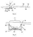
- Figure 5 shows a cross section of a plastic glass 54.
- the mirror glass 54 has a front side 60 that is visible for the driver.
- a reflective surface 56 reflects light in the visible spectrum.
- the reflective material is normally a metal or an alloy that is sputtered onto the plastic substrate.
- a cover layer for example a hard coating is used.
- reflective material is deleted totally or to a defined remaining thickness by laser engraving. It is possible to use a very thin remaining reflective surface 56 which appears semi-transparent to operator.
- the plastic mirror 54 forms an integrated mounting space 53 that hosts the indicator light.
- the mounting space is formed to cover at least a printed circuit board 57, a light source 64 and a cover 58.
- the printed circuit board 57 is mounted at the walls 52 of the mounting space 53 and the light source in form of a LED is attached on the top of the printed circuit board.
- the mounting space 53 forms shoulders 61 to be used as bearing faces for the cover 58.
- the forces of covering the mounting space 53 are spread broader if the area of contact between walls and plastic mirror is bigger. Than stress issues that can disturb the appearance of the reflective first side of the plastic mirror are reduced.
- special wall form are designed that increases the contact areas and that are easily and strain less connected.
- the cover is formed as a plate to close the mounting space.
- the plastic mirror forms a plate a light guiding pin 59 too.
- the light guiding pin is directed in direction to the LED 64 and inclined versus the vertical by an angle theta. The angle theta allows a direction of light from the light source 64 into the light guide pin 59 through the circle opening 51 and the plastic mirror 54 to driver's eyes.
- the dimension of the optical indicator is small.
- the height of the mounting space is only limited by the size of LEDs and the related electrical connections and the printed circuit board and the optical element 66.
- the light shines through symbols that are prepared out of the reflective layer of the mirror glass to be visible by the driver.
- FIG. 6 shows an alternative solution using an optical element 66 that is a total internal reflection TIR lens.
- a TIR lens is well adapted to sample light of a LED and direct the light against the end surface.
- the TIR lens 66 is designed to create a light travel space 67 around the LED 64. The space is covering the light emission angle of the LED totally.
- the TIR lens has a convex end face 68 that concentrates light.
- the TIR lens is molded in one piece with the plastic mirror 54 and the walls 52 of the mounting space.
- the TIR lens has in this example an end facet 71 which is flat.
- the LED is a top mounted LED welded to the printed circuit board 57.
- the top mounted LED is in this embodiment covered by a lens 72.
- Figure 7 shows different alternatives of the optical element 66 molded in one piece with plastic mirror.
- the molded TIR lens can be structured in different ways.
- the structure 7a is a prismatic structure 70 that can cover the end facet 71 of the lens 66.
- the prismatic structure70 can be also applied to the side faces 72 of the lens 66 and / or to the convex end face 68.
- End facet 71 can be structures to follow a curved form as a convex or concave form 69 as shown in Figure 7b .
- An additional convex lens 73 can be designed in the end facet 71.
- the surface 56 of the plastic mirror is modified to remove reflective layer from the substrate. This can be done after producing and assembling the mirror with optical indicator 62 or during the process of coating the reflective layer to the substrate by using a mask.
- the integrated optical indicator solution can be used also as turn signal indicator and more than one single LED can be mounted to illuminate the indicator.
- the optical elements must be related to the single LEDs to direct light according to legal or customer requirements.
Landscapes
- Engineering & Computer Science (AREA)
- Multimedia (AREA)
- Mechanical Engineering (AREA)
- Rear-View Mirror Devices That Are Mounted On The Exterior Of The Vehicle (AREA)
- Optical Elements Other Than Lenses (AREA)
Abstract
Description
- The invention relates to an assembly with an optical indicator placed in a side rear view mirror assembly for a motor vehicle. More particularly, the invention relates to an optical indicator that is mounted to shine through the plastic mirror of a side rear view mirror assembly and is preferably used as an alert signal. to identify when an object is occupying the blind spot of the motor vehicle.
- The driver of a motor vehicle must recognize that objects such as other motor vehicles move with respect to the motor vehicle being driven by the driver. As such, the driver must constantly review his or her surroundings to determine whether a desired path of travel is not obstructed or, if taken, would cause a collision. Tools that assist a driver in reviewing the space surrounding the motor vehicle include the rear view mirror and the side rear view mirrors. These mirrors allow the driver to review the surroundings generally disposed behind the driver without the driver having to turn his or her head more than a minimal amount. Locations commonly referred to as "blind spots" exist on either side of the motor vehicle. These blind spots are spaces that are not visible to the driver when the driver is looking in the mirrors and viewing of these blind spots requires the driver to turn his or her head to look to see if another motor vehicle or some other object has entered the blind spots. To overcome this problem, blind spot indicators have sensors that identify when objects enter blind spots. These sensors notify the driver that a blind spot is now being occupied. Indicators in the art include light generators and sound generators. Placement of these generators is critical as it is in the best interests of the driver to have these located within the driver's peripheral vision and in an area where the driver frequently looks.
- Optical indicators are used to notify the driver of a vehicle that a hazardous situation has been recognized by automatic sensors. Blind spot detection is one of these alert indications. There are other hazardous situations that can be detected by sensors and indicated with the alert indicator. Examples are a distance control, surrounding monitoring, crash warning, temperature indication and ice warning, status indications etc.
- Conventional glass mirrors for automotive use are heavy (especially with the trend towards larger mirrors), tend to be difficult to form aspheric or complex shapes, and are prone to shatter in the case of accidents. The replacement of glass with a plastic substrate would offer the ability to reduce weight, mould complex shapes, integrate retention features on the rear surface of the substrate, and achieve a high level of impact resistance. However, plastic substrates tend to be soft, would be readily damaged by UV radiation, heat and water, and would have a propensity towards causing the reflective surface to craze.
- In addition to the softness problems that would expect to be introduced by the use of a plastic substrate for mirrors, some reflective layers typically used for mirrors (of any type) that are formed from direct metal deposition (such as of aluminium or silver) also themselves tend to be soft. To minimise this problem with glass substrates, most reflective layers are conventionally applied to the rear surface. However, for reflective metals such as chromium, which are harder and more resistant to the elements by virtue of their chemical and mechanical properties, these metals are predominantly applied to the front surface of glass substrates. However, if this were attempted with a plastic substrate, it would be expected that the reflective coating would exhibit crazing, which would be made worse in durability testing such as thermal cycling, and which would likely also fail other standard tests such as a salt spray test.
- In the case of plastic mirrors, the reflective layer could be applied to the rear or front surface and a hard coating applied in order to provide environmental exposure protection of the plastic substrate and the reflective coating, whilst providing improved abrasion resistance. However, for an automotive application, a rear surface plastic mirror has not been regarded as suitable as it would be interrupted by any retention/clipping features on the rear of the mirror. Also, in the case of an applied hard coating, interference bands would be present which are cosmetically unacceptable. So the objective is to manufacture a plastic mirror, suitable for automotive applications, which does not craze, which does not have interference fringes and which passes the normal automotive tests such as a salt spray test, thermal cycling and shock tests, and accelerated weathering tests.
- This type of plastic mirror is for example known from the not published application
AU2009906281 - It is known from
US6276821 to mount an indicator behind a mirror glass to shine through the reflective surface. In figure 44 of the prior art an example is shown, that comprises a backing plate with an integrated device that covers a LED and a light guide structure. The backing plate is connected to the mirror glass and is adjustable mounted in the mirror head. - The prior art solution does not fulfill the need to direct light to driver's eyes in a sufficient way and to be designed for an easy and cost efficient way and combine the optimized solution with a plastic mirror.
- A side rear view mirror assembly is used in conjunction with a motor vehicle equipped with a blind spot sensor designed to detect objects in blind spots of the motor vehicle. The side rear view mirror assembly includes a base fixedly secured to the motor vehicle. A mirror case can be movably secured to the base. The mirror case defines a housing and a mirror opening facing rearward. A plastic mirror is secured in a manner allowing an operator of the motor vehicle to view rearward of the motor vehicle. The side rear view mirror assembly also includes a blind spot indicator fixedly secured to the plastic glass and in communication with the blind spot sensor to receive signals from the blind spot sensor and to indicate to the operator of the motor vehicle when an object is in a blind spot of the motor vehicle. The blind spot indicator is directed at the operator. The indicator is integrated into the plastic glass and has a small height. The optical indicator is structured with at least one light source and alight guide designed to direct light to operator's eyes. The light guide is integrated into the second surface of the plastic mirror. An alternative design could include a diffuser integrated into the second surface of the plastic mirror.
- Advantages of the invention will be readily appreciated as the same becomes better understood by reference to the following detailed description when considered in connection with the accompanying drawings, wherein:
-
Figure 1 is a top view of a motor vehicle with a second motor vehicle located in a blind spot of the first motor vehicle; -
Figure 2 is a perspective view of one indicator in prior art -
Figure 3 is a view of mirror glass with indication signs; -
Figure 4 is a cross section of a first embodiment -
Figure 5 shows a second embodiment of invention -
Figure 6 shows another embodiment of invention -
Figure 7 shows integrated solutions - Referring to
Figure 1 , amotor vehicle 10 is shown driving along aroad 12 that has adashed line 14 indicating a boundary of a lane of theroad 12. Themotor vehicle 10 is equipped withblind spot sensors motor vehicle 10. Themotor vehicle 10 is also equipped with two side rearview mirror assemblies 24, 26 that extend out from each of these sides 20, 22 respectively. The side rearview mirror assemblies 24, 26 are used by an operator, graphically represented by acircle 28 inFigure 1 , to identify things that are going on outside themotor vehicle 10 rearwardly thereof. Theoperator 28 will adjust the side rearview mirror assemblies 24, 26 in a manner which allows theoperator 28 to be satisfied that as much of the space rearward that can be viewed is being viewed by theoperator 28. While most, if not all,motor vehicles 10 are equipped with two side rearview mirror assemblies 24, 26, the remainder of the discussion will focus on the side rear view mirror assembly 26 that is on the driver side 22 of themotor vehicle 10. It will be appreciated by those skilled in the art that the following discussion with regard to the driver side rear view mirror assembly 26 applies equally to the passenger side rearview mirror assembly 24. - When an
operator 28 uses a side rear view mirror assembly 26, it is typically adjusted such that the orientation of the mirror includes a portion of the driver side 22 of the motor vehicle therein. Theoperator 28 does this for purposes of orientation. As is shown inFigure 1 , the field of view for the side view mirror generally includes an angle α. Disposed adjacent the field ofview 29 that is visible to theoperator 28 is what is commonly referred to as ablind spot 31 that extends generally through an angle β. Theoperator 28 cannot see what is in theblind spot 31, crosshatched inFigure 1 without turning the head of theoperator 28 in that direction. Said another way, theoperator 28 cannot see anything that is in theblind spot 31 through angle β by looking in the side rear view mirror assembly 26. It is theblind spot sensor 18 that determines whether anobject 30, a motor vehicle shown inFigure 1 , is in the blind spot. If so, theblind spot sensor 18 will transmit over the vehicle communication system an appropriate signal to eventually indicate to theoperator 28 that an object does in fact exist in theblind spot 31. It will be the operator's decision as to whether theoperator 28 will turn his or her head to view theobject 30 or to operate as if theobject 30 continues to be in theblind spot 31 and act accordingly with regard to the operation and direction of travel of themotor vehicle 10. - Referring to
Figure 2 , the side rear view mirror assembly is generally indicated at 26. The perspective of this Figure is from that of theoperator 28 as theoperator 28 looks into the side rear view mirror assembly 26 to see that which is rearward of theoperator 28 and a portion of themotor vehicle 10.Figure 2 includes a portion of adoor 32 and awindow 34. - The side rear view mirror assembly includes a base 38 that is fixedly secured to the
motor vehicle 10 and, more specifically, thedoor 32 of themotor vehicle 10. The base 38 may or may not include a sail similar to the one shown inFigure 2 . Thebase 38 is secured to thedoor 32 through known means. Depending on the design of thebase 38, thebase 38 may include either a lowerrear wall 37 or an upper rear wall 39, or both. - The side rear view mirror assembly 26 also includes a mirror case 40 that is movably secured to the
base 38. The mirror case 40 is movable in that it may be pivoted about the base 38 to allow the mirror case 40 to move closer to the side 22 of themotor vehicle 10 when situations require a narrower profile ofmotor vehicle 10. The pivoting of the mirror case 40 also comes in handy when the motor vehicle moves with respect to a fixed object in close proximity therewith such that the mirror case 40 is pushed in one direction or another due to the relative tightness of the position at which themotor vehicle 10 is operating. - The mirror case 40 defines a
housing 42 and amirror opening 44. Themirror opening 44 faces rearward with respect to forward direction of themotor vehicle 10. The mirror case 40 may include additional openings other than themirror opening 44 for side markers, turn signals, security lights, sensors or cameras and the like. Otherwise, the mirror case 40 includes ahousing 42 that is aerodynamic and aesthetically similar to the general design of themotor vehicle 10. Theblind spot indicator 62 is positioned adjacent of the plastic mirror or behind the plastic mirror. Theblind spot indicator 62 includes alight source 64 that is illuminated when theblind spot sensor 18 senses the presence of theobject 30 in the blind spot of themotor vehicle 10. -
Fig 3 shows a view on the front side of a plastic mirror. Theplastic mirror 54 is molded to fit into the mirror opening 44 of a rear view mirror assembly. The outer side of the plastic mirror is coated with a reflective layer. On the left outer side of the plastic mirror 54 asmall icon 50 is engraved in the reflective layer that shows the ISO symbol of two vehicles in an overtaking position. Below this symbol acircle 51 is visible, through which the light of indicator shines in direction tooperator 28. In the area of the circle the second inner side of the plastic mirror bears an optical element. -
Figure 4 shows a first schematic cross section of the indicator integrated into a plastic mirror. Theplastic mirror 54 is molded withwalls 52 at thesecond surface 65 of the plastic mirror. Thewalls 52 form a sealed mountingspace 53 for the optical indicator. In addition anoptical element 66 is molded together with the plastic mirror and the walls. - The sealed mounting
space 53 is adapted to the size of a printedcircuit board 57 that is installed in the opening. An LED light source, 64 is mounted to the printedcircuit board 57. TheLED 64 is mounted to provide light in the direction of theoptical element 66 of the plastic mirror. - The
walls 52 of the plastic mirror are formed with shoulders or edges to support the printed circuit board and to locate and fix it in the mounting space. A cover orencapsulation 58 closes the mounting space of the optical indicator to seal it from dirt and moisture influences. The encapsulation could be a resin which permanently covers the PCB or a cover which is a separate moulding that allows serviceability of the light source. - The cover can have an opening as lead through for the electrical connection of the
optical indicator 62. -
Figure 5 shows a cross section of aplastic glass 54. Themirror glass 54 has afront side 60 that is visible for the driver. On the front side areflective surface 56 reflects light in the visible spectrum. The reflective material is normally a metal or an alloy that is sputtered onto the plastic substrate. To protect the reflective surface a cover layer for example a hard coating is used. In the area of thecircle 51 reflective material is deleted totally or to a defined remaining thickness by laser engraving. It is possible to use a very thin remainingreflective surface 56 which appears semi-transparent to operator. - The
plastic mirror 54 forms an integrated mountingspace 53 that hosts the indicator light. The mounting space is formed to cover at least a printedcircuit board 57, alight source 64 and acover 58. - The printed
circuit board 57 is mounted at thewalls 52 of the mountingspace 53 and the light source in form of a LED is attached on the top of the printed circuit board. The mountingspace 53 forms shoulders 61 to be used as bearing faces for thecover 58. The forces of covering the mountingspace 53 are spread broader if the area of contact between walls and plastic mirror is bigger. Than stress issues that can disturb the appearance of the reflective first side of the plastic mirror are reduced. For this purpose special wall form are designed that increases the contact areas and that are easily and strain less connected. - The cover is formed as a plate to close the mounting space. The plastic mirror forms a plate a
light guiding pin 59 too. The light guiding pin is directed in direction to theLED 64 and inclined versus the vertical by an angle theta. The angle theta allows a direction of light from thelight source 64 into thelight guide pin 59 through thecircle opening 51 and theplastic mirror 54 to driver's eyes. - For the indicator does not use a reflector the dimension of the optical indicator is small. The height of the mounting space is only limited by the size of LEDs and the related electrical connections and the printed circuit board and the
optical element 66. - The light shines through symbols that are prepared out of the reflective layer of the mirror glass to be visible by the driver.
-
Figure 6 shows an alternative solution using anoptical element 66 that is a total internal reflection TIR lens. A TIR lens is well adapted to sample light of a LED and direct the light against the end surface. TheTIR lens 66 is designed to create alight travel space 67 around theLED 64. The space is covering the light emission angle of the LED totally. The TIR lens has aconvex end face 68 that concentrates light. The TIR lens is molded in one piece with theplastic mirror 54 and thewalls 52 of the mounting space. The TIR lens has in this example anend facet 71 which is flat. - The LED is a top mounted LED welded to the printed
circuit board 57. The top mounted LED is in this embodiment covered by alens 72. -
Figure 7 shows different alternatives of theoptical element 66 molded in one piece with plastic mirror. The molded TIR lens can be structured in different ways. The structure 7a is aprismatic structure 70 that can cover theend facet 71 of thelens 66. The prismatic structure70 can be also applied to the side faces 72 of thelens 66 and / or to theconvex end face 68. -
End facet 71 can be structures to follow a curved form as a convex orconcave form 69 as shown inFigure 7b . An additionalconvex lens 73 can be designed in theend facet 71. - The
surface 56 of the plastic mirror is modified to remove reflective layer from the substrate. This can be done after producing and assembling the mirror withoptical indicator 62 or during the process of coating the reflective layer to the substrate by using a mask. - Any form of the indication sign and the mounting space is possible to achieve the integrated solution.
- The integrated optical indicator solution can be used also as turn signal indicator and more than one single LED can be mounted to illuminate the indicator.
- If more than one LED is used the optical elements must be related to the single LEDs to direct light according to legal or customer requirements.
-
- 10
- motor vehicle
- 12
- road
- 14
- dashed line
- 16, 18
- blind spot sensors
- 20, 22
- side of the motor vehicle
- 24, 26
- side rear view mirror assemblies
- 28
- operator
- 29
- field of view
- 30
- object
- 31
- blind spot
- 32
- portion of a door
- 34
- window
- 38
- base
- 37
- lower rear wall
- 39
- upper rear wall
- 40
- mirror case
- 42
- mirror housing
- 44
- mirror opening
- 50
- symbol
- 51
- circle
- 52
- wall
- 53
- mounting space
- 54
- Plastic Mirror
- 56
- reflective first surface
- 57
- printed circuit
- 58
- cover
- 59
- light guide pin
- 60
-
front side shoulder 62 indicator 63 end area ofcover 64light source 65Second Side 66Optical element 67Light travel space 68convex end facet 69Convex structure 70prismatic structure 71end facet 72 side face - 73
- lens
Claims (11)
- A plastic mirror (54) for automotive use having a shape that fits to a mirror housing (42) of a mirror assembly attached to a vehicle and having a first surface (56) at least coated with reflective material, characterized in that an optical element (66) is integrally formed in the plastic mirror's second surface (65).
- A plastic mirror (54) according to claim 1 characterised in that the second surface contains attachment means (52)
- A plastic mirror (54) according claim 1 characterized in that the optical element forms a lens.
- A plastic mirror (54) according claim 1 characterized in that the optical element forms a TIR lens.
- A plastic mirror (54) according claim 1 characterized in that the optical element forms a light guide pin (59).
- A plastic mirror (54) according claim 1 characterized in that the optical element (66) covers at least one LED (64).
- A plastic mirror (54) according claim 1 characterized in that the optical element (66) has a convex, flat or concave inner facet (68).
- A plastic mirror (54) according claim 1 characterized in that the optical element (66) has a convex, flat or concave outer facet (71).
- A plastic mirror (54) according claim 1 characterized in that the outer facet (71) has a structure of prismatic elements (70) at least at one outer surface of the optical element.
- A plastic mirror (54) according claim 1 characterized in that the attachment means form walls to create a mounting space (53).
- A plastic mirror (54) according claim 1 characterized in that the mounting space hosts a printed circuit board with mounted LED (64) and is enclosed by a cover or encapsulate (58).
Priority Applications (1)
| Application Number | Priority Date | Filing Date | Title |
|---|---|---|---|
| EP11152485.6A EP2481638B1 (en) | 2011-01-28 | 2011-01-28 | Rear view mirror assembly with optical indicator |
Applications Claiming Priority (1)
| Application Number | Priority Date | Filing Date | Title |
|---|---|---|---|
| EP11152485.6A EP2481638B1 (en) | 2011-01-28 | 2011-01-28 | Rear view mirror assembly with optical indicator |
Publications (2)
| Publication Number | Publication Date |
|---|---|
| EP2481638A1 true EP2481638A1 (en) | 2012-08-01 |
| EP2481638B1 EP2481638B1 (en) | 2013-07-31 |
Family
ID=43928515
Family Applications (1)
| Application Number | Title | Priority Date | Filing Date |
|---|---|---|---|
| EP11152485.6A Active EP2481638B1 (en) | 2011-01-28 | 2011-01-28 | Rear view mirror assembly with optical indicator |
Country Status (1)
| Country | Link |
|---|---|
| EP (1) | EP2481638B1 (en) |
Cited By (3)
| Publication number | Priority date | Publication date | Assignee | Title |
|---|---|---|---|---|
| DE102012107339A1 (en) | 2011-08-10 | 2013-02-14 | SMR Patents S.à.r.l. | Exterior rearview mirror assembly |
| JP2016007891A (en) * | 2014-06-23 | 2016-01-18 | 株式会社東海理化電機製作所 | Vehicle mirror device |
| CN105329157A (en) * | 2015-11-16 | 2016-02-17 | 重庆奥科伦实业发展有限公司 | Lamp housing of blind area alarming lamp assembly and blind area alarming lamp assembly |
Citations (6)
| Publication number | Priority date | Publication date | Assignee | Title |
|---|---|---|---|---|
| GB2105866A (en) * | 1981-07-29 | 1983-03-30 | Lynell Med Tech Inc | Intraocular and extraocular lens construction and making by selective erosion |
| US6276821B1 (en) | 1992-12-16 | 2001-08-21 | Donnelly Corporation | Vehicle exterior mirror system with signal light |
| US20030002179A1 (en) * | 1997-04-02 | 2003-01-02 | Roberts John K. | Indicators and iluminators using a semiconductor radiation emitter package |
| US20030001301A1 (en) * | 2001-07-02 | 2003-01-02 | Bernard Duroux | Plastic glass |
| US6523976B1 (en) * | 1996-06-13 | 2003-02-25 | Gentex Corporation | Led assembly |
| US20040084681A1 (en) * | 1998-09-04 | 2004-05-06 | Roberts John K. | Radiation emitter device having an integral micro-groove lens |
-
2011
- 2011-01-28 EP EP11152485.6A patent/EP2481638B1/en active Active
Patent Citations (6)
| Publication number | Priority date | Publication date | Assignee | Title |
|---|---|---|---|---|
| GB2105866A (en) * | 1981-07-29 | 1983-03-30 | Lynell Med Tech Inc | Intraocular and extraocular lens construction and making by selective erosion |
| US6276821B1 (en) | 1992-12-16 | 2001-08-21 | Donnelly Corporation | Vehicle exterior mirror system with signal light |
| US6523976B1 (en) * | 1996-06-13 | 2003-02-25 | Gentex Corporation | Led assembly |
| US20030002179A1 (en) * | 1997-04-02 | 2003-01-02 | Roberts John K. | Indicators and iluminators using a semiconductor radiation emitter package |
| US20040084681A1 (en) * | 1998-09-04 | 2004-05-06 | Roberts John K. | Radiation emitter device having an integral micro-groove lens |
| US20030001301A1 (en) * | 2001-07-02 | 2003-01-02 | Bernard Duroux | Plastic glass |
Cited By (5)
| Publication number | Priority date | Publication date | Assignee | Title |
|---|---|---|---|---|
| DE102012107339A1 (en) | 2011-08-10 | 2013-02-14 | SMR Patents S.à.r.l. | Exterior rearview mirror assembly |
| US8779911B2 (en) | 2011-08-10 | 2014-07-15 | Smr Patents S.A.R.L. | Vehicular mirror with blind spot indicator |
| DE102012107339B4 (en) | 2011-08-10 | 2018-11-22 | SMR Patents S.à.r.l. | Exterior rearview mirror assembly |
| JP2016007891A (en) * | 2014-06-23 | 2016-01-18 | 株式会社東海理化電機製作所 | Vehicle mirror device |
| CN105329157A (en) * | 2015-11-16 | 2016-02-17 | 重庆奥科伦实业发展有限公司 | Lamp housing of blind area alarming lamp assembly and blind area alarming lamp assembly |
Also Published As
| Publication number | Publication date |
|---|---|
| EP2481638B1 (en) | 2013-07-31 |
Similar Documents
| Publication | Publication Date | Title |
|---|---|---|
| EP2463157B1 (en) | Rear view mirror assembly with optical indicator | |
| US8770810B2 (en) | Rear view mirror assembly with optical indicator | |
| US11077801B2 (en) | Vehicular exterior rearview mirror assembly with blind spot indicator module | |
| EP2151350B1 (en) | Exterior rear view mirror with indicator light | |
| EP2380776B1 (en) | Side rear view mirror assembly indicator of blind spot occupancy | |
| EP1902338B1 (en) | Vehicle exterior mirror assembly with blind spot indicator | |
| AU2012211407A1 (en) | Vehicular mirror with blind spot indicator | |
| EP2481638B1 (en) | Rear view mirror assembly with optical indicator | |
| EP3580610B1 (en) | Optical device cover | |
| US11890991B2 (en) | Vehicular exterior rearview mirror assembly with blind spot indicator element | |
| US12488690B2 (en) | Blind spot indicator assembly for a motor vehicle and rear-view mirror comprising said blind spot indicator assembly | |
| EP1743803B1 (en) | Mirror | |
| EP3458309B1 (en) | Backing plate unit, method for producing such a backing plate unit and rear view device for a motor vehicle with such a backing plate unit | |
| CN114667456B (en) | Roof module with roof cladding and environmental sensors |
Legal Events
| Date | Code | Title | Description |
|---|---|---|---|
| PUAI | Public reference made under article 153(3) epc to a published international application that has entered the european phase |
Free format text: ORIGINAL CODE: 0009012 |
|
| AK | Designated contracting states |
Kind code of ref document: A1 Designated state(s): AL AT BE BG CH CY CZ DE DK EE ES FI FR GB GR HR HU IE IS IT LI LT LU LV MC MK MT NL NO PL PT RO RS SE SI SK SM TR |
|
| AX | Request for extension of the european patent |
Extension state: BA ME |
|
| 17P | Request for examination filed |
Effective date: 20130111 |
|
| GRAP | Despatch of communication of intention to grant a patent |
Free format text: ORIGINAL CODE: EPIDOSNIGR1 |
|
| RIC1 | Information provided on ipc code assigned before grant |
Ipc: B60R 1/12 20060101ALI20130301BHEP Ipc: B29D 11/00 20060101ALI20130301BHEP Ipc: B60R 1/08 20060101AFI20130301BHEP |
|
| INTG | Intention to grant announced |
Effective date: 20130404 |
|
| GRAS | Grant fee paid |
Free format text: ORIGINAL CODE: EPIDOSNIGR3 |
|
| GRAA | (expected) grant |
Free format text: ORIGINAL CODE: 0009210 |
|
| AK | Designated contracting states |
Kind code of ref document: B1 Designated state(s): AL AT BE BG CH CY CZ DE DK EE ES FI FR GB GR HR HU IE IS IT LI LT LU LV MC MK MT NL NO PL PT RO RS SE SI SK SM TR |
|
| REG | Reference to a national code |
Ref country code: GB Ref legal event code: FG4D Ref country code: CH Ref legal event code: EP |
|
| REG | Reference to a national code |
Ref country code: AT Ref legal event code: REF Ref document number: 624406 Country of ref document: AT Kind code of ref document: T Effective date: 20130815 |
|
| REG | Reference to a national code |
Ref country code: IE Ref legal event code: FG4D |
|
| REG | Reference to a national code |
Ref country code: DE Ref legal event code: R096 Ref document number: 602011002490 Country of ref document: DE Effective date: 20130926 |
|
| REG | Reference to a national code |
Ref country code: AT Ref legal event code: MK05 Ref document number: 624406 Country of ref document: AT Kind code of ref document: T Effective date: 20130731 |
|
| REG | Reference to a national code |
Ref country code: NL Ref legal event code: VDEP Effective date: 20130731 |
|
| REG | Reference to a national code |
Ref country code: LT Ref legal event code: MG4D |
|
| PG25 | Lapsed in a contracting state [announced via postgrant information from national office to epo] |
Ref country code: AT Free format text: LAPSE BECAUSE OF FAILURE TO SUBMIT A TRANSLATION OF THE DESCRIPTION OR TO PAY THE FEE WITHIN THE PRESCRIBED TIME-LIMIT Effective date: 20130731 Ref country code: CY Free format text: LAPSE BECAUSE OF FAILURE TO SUBMIT A TRANSLATION OF THE DESCRIPTION OR TO PAY THE FEE WITHIN THE PRESCRIBED TIME-LIMIT Effective date: 20130904 Ref country code: PT Free format text: LAPSE BECAUSE OF FAILURE TO SUBMIT A TRANSLATION OF THE DESCRIPTION OR TO PAY THE FEE WITHIN THE PRESCRIBED TIME-LIMIT Effective date: 20131202 Ref country code: IS Free format text: LAPSE BECAUSE OF FAILURE TO SUBMIT A TRANSLATION OF THE DESCRIPTION OR TO PAY THE FEE WITHIN THE PRESCRIBED TIME-LIMIT Effective date: 20131130 Ref country code: HR Free format text: LAPSE BECAUSE OF FAILURE TO SUBMIT A TRANSLATION OF THE DESCRIPTION OR TO PAY THE FEE WITHIN THE PRESCRIBED TIME-LIMIT Effective date: 20130731 Ref country code: LT Free format text: LAPSE BECAUSE OF FAILURE TO SUBMIT A TRANSLATION OF THE DESCRIPTION OR TO PAY THE FEE WITHIN THE PRESCRIBED TIME-LIMIT Effective date: 20130731 Ref country code: SE Free format text: LAPSE BECAUSE OF FAILURE TO SUBMIT A TRANSLATION OF THE DESCRIPTION OR TO PAY THE FEE WITHIN THE PRESCRIBED TIME-LIMIT Effective date: 20130731 Ref country code: BE Free format text: LAPSE BECAUSE OF FAILURE TO SUBMIT A TRANSLATION OF THE DESCRIPTION OR TO PAY THE FEE WITHIN THE PRESCRIBED TIME-LIMIT Effective date: 20130731 Ref country code: NO Free format text: LAPSE BECAUSE OF FAILURE TO SUBMIT A TRANSLATION OF THE DESCRIPTION OR TO PAY THE FEE WITHIN THE PRESCRIBED TIME-LIMIT Effective date: 20131031 |
|
| PG25 | Lapsed in a contracting state [announced via postgrant information from national office to epo] |
Ref country code: LV Free format text: LAPSE BECAUSE OF FAILURE TO SUBMIT A TRANSLATION OF THE DESCRIPTION OR TO PAY THE FEE WITHIN THE PRESCRIBED TIME-LIMIT Effective date: 20130731 Ref country code: NL Free format text: LAPSE BECAUSE OF FAILURE TO SUBMIT A TRANSLATION OF THE DESCRIPTION OR TO PAY THE FEE WITHIN THE PRESCRIBED TIME-LIMIT Effective date: 20130731 Ref country code: GR Free format text: LAPSE BECAUSE OF FAILURE TO SUBMIT A TRANSLATION OF THE DESCRIPTION OR TO PAY THE FEE WITHIN THE PRESCRIBED TIME-LIMIT Effective date: 20131101 Ref country code: FI Free format text: LAPSE BECAUSE OF FAILURE TO SUBMIT A TRANSLATION OF THE DESCRIPTION OR TO PAY THE FEE WITHIN THE PRESCRIBED TIME-LIMIT Effective date: 20130731 Ref country code: PL Free format text: LAPSE BECAUSE OF FAILURE TO SUBMIT A TRANSLATION OF THE DESCRIPTION OR TO PAY THE FEE WITHIN THE PRESCRIBED TIME-LIMIT Effective date: 20130731 Ref country code: SI Free format text: LAPSE BECAUSE OF FAILURE TO SUBMIT A TRANSLATION OF THE DESCRIPTION OR TO PAY THE FEE WITHIN THE PRESCRIBED TIME-LIMIT Effective date: 20130731 |
|
| PG25 | Lapsed in a contracting state [announced via postgrant information from national office to epo] |
Ref country code: CY Free format text: LAPSE BECAUSE OF FAILURE TO SUBMIT A TRANSLATION OF THE DESCRIPTION OR TO PAY THE FEE WITHIN THE PRESCRIBED TIME-LIMIT Effective date: 20130731 |
|
| PG25 | Lapsed in a contracting state [announced via postgrant information from national office to epo] |
Ref country code: CZ Free format text: LAPSE BECAUSE OF FAILURE TO SUBMIT A TRANSLATION OF THE DESCRIPTION OR TO PAY THE FEE WITHIN THE PRESCRIBED TIME-LIMIT Effective date: 20130731 Ref country code: EE Free format text: LAPSE BECAUSE OF FAILURE TO SUBMIT A TRANSLATION OF THE DESCRIPTION OR TO PAY THE FEE WITHIN THE PRESCRIBED TIME-LIMIT Effective date: 20130731 Ref country code: DK Free format text: LAPSE BECAUSE OF FAILURE TO SUBMIT A TRANSLATION OF THE DESCRIPTION OR TO PAY THE FEE WITHIN THE PRESCRIBED TIME-LIMIT Effective date: 20130731 Ref country code: SK Free format text: LAPSE BECAUSE OF FAILURE TO SUBMIT A TRANSLATION OF THE DESCRIPTION OR TO PAY THE FEE WITHIN THE PRESCRIBED TIME-LIMIT Effective date: 20130731 Ref country code: RO Free format text: LAPSE BECAUSE OF FAILURE TO SUBMIT A TRANSLATION OF THE DESCRIPTION OR TO PAY THE FEE WITHIN THE PRESCRIBED TIME-LIMIT Effective date: 20130731 |
|
| PG25 | Lapsed in a contracting state [announced via postgrant information from national office to epo] |
Ref country code: ES Free format text: LAPSE BECAUSE OF FAILURE TO SUBMIT A TRANSLATION OF THE DESCRIPTION OR TO PAY THE FEE WITHIN THE PRESCRIBED TIME-LIMIT Effective date: 20130731 Ref country code: IT Free format text: LAPSE BECAUSE OF FAILURE TO SUBMIT A TRANSLATION OF THE DESCRIPTION OR TO PAY THE FEE WITHIN THE PRESCRIBED TIME-LIMIT Effective date: 20130731 |
|
| PLBE | No opposition filed within time limit |
Free format text: ORIGINAL CODE: 0009261 |
|
| STAA | Information on the status of an ep patent application or granted ep patent |
Free format text: STATUS: NO OPPOSITION FILED WITHIN TIME LIMIT |
|
| 26N | No opposition filed |
Effective date: 20140502 |
|
| REG | Reference to a national code |
Ref country code: DE Ref legal event code: R097 Ref document number: 602011002490 Country of ref document: DE Effective date: 20140502 |
|
| PG25 | Lapsed in a contracting state [announced via postgrant information from national office to epo] |
Ref country code: LU Free format text: LAPSE BECAUSE OF FAILURE TO SUBMIT A TRANSLATION OF THE DESCRIPTION OR TO PAY THE FEE WITHIN THE PRESCRIBED TIME-LIMIT Effective date: 20140128 |
|
| REG | Reference to a national code |
Ref country code: CH Ref legal event code: PL |
|
| PG25 | Lapsed in a contracting state [announced via postgrant information from national office to epo] |
Ref country code: CH Free format text: LAPSE BECAUSE OF NON-PAYMENT OF DUE FEES Effective date: 20140131 Ref country code: LI Free format text: LAPSE BECAUSE OF NON-PAYMENT OF DUE FEES Effective date: 20140131 |
|
| REG | Reference to a national code |
Ref country code: IE Ref legal event code: MM4A |
|
| PG25 | Lapsed in a contracting state [announced via postgrant information from national office to epo] |
Ref country code: IE Free format text: LAPSE BECAUSE OF NON-PAYMENT OF DUE FEES Effective date: 20140128 |
|
| PG25 | Lapsed in a contracting state [announced via postgrant information from national office to epo] |
Ref country code: MC Free format text: LAPSE BECAUSE OF FAILURE TO SUBMIT A TRANSLATION OF THE DESCRIPTION OR TO PAY THE FEE WITHIN THE PRESCRIBED TIME-LIMIT Effective date: 20130731 |
|
| REG | Reference to a national code |
Ref country code: FR Ref legal event code: PLFP Year of fee payment: 6 |
|
| PG25 | Lapsed in a contracting state [announced via postgrant information from national office to epo] |
Ref country code: MT Free format text: LAPSE BECAUSE OF FAILURE TO SUBMIT A TRANSLATION OF THE DESCRIPTION OR TO PAY THE FEE WITHIN THE PRESCRIBED TIME-LIMIT Effective date: 20130731 |
|
| PG25 | Lapsed in a contracting state [announced via postgrant information from national office to epo] |
Ref country code: SM Free format text: LAPSE BECAUSE OF FAILURE TO SUBMIT A TRANSLATION OF THE DESCRIPTION OR TO PAY THE FEE WITHIN THE PRESCRIBED TIME-LIMIT Effective date: 20130731 |
|
| PG25 | Lapsed in a contracting state [announced via postgrant information from national office to epo] |
Ref country code: BG Free format text: LAPSE BECAUSE OF FAILURE TO SUBMIT A TRANSLATION OF THE DESCRIPTION OR TO PAY THE FEE WITHIN THE PRESCRIBED TIME-LIMIT Effective date: 20130731 Ref country code: RS Free format text: LAPSE BECAUSE OF FAILURE TO SUBMIT A TRANSLATION OF THE DESCRIPTION OR TO PAY THE FEE WITHIN THE PRESCRIBED TIME-LIMIT Effective date: 20130731 |
|
| PG25 | Lapsed in a contracting state [announced via postgrant information from national office to epo] |
Ref country code: TR Free format text: LAPSE BECAUSE OF FAILURE TO SUBMIT A TRANSLATION OF THE DESCRIPTION OR TO PAY THE FEE WITHIN THE PRESCRIBED TIME-LIMIT Effective date: 20130731 Ref country code: HU Free format text: LAPSE BECAUSE OF FAILURE TO SUBMIT A TRANSLATION OF THE DESCRIPTION OR TO PAY THE FEE WITHIN THE PRESCRIBED TIME-LIMIT; INVALID AB INITIO Effective date: 20110128 |
|
| REG | Reference to a national code |
Ref country code: FR Ref legal event code: PLFP Year of fee payment: 7 |
|
| REG | Reference to a national code |
Ref country code: FR Ref legal event code: PLFP Year of fee payment: 8 |
|
| PG25 | Lapsed in a contracting state [announced via postgrant information from national office to epo] |
Ref country code: MK Free format text: LAPSE BECAUSE OF FAILURE TO SUBMIT A TRANSLATION OF THE DESCRIPTION OR TO PAY THE FEE WITHIN THE PRESCRIBED TIME-LIMIT Effective date: 20130731 |
|
| PG25 | Lapsed in a contracting state [announced via postgrant information from national office to epo] |
Ref country code: AL Free format text: LAPSE BECAUSE OF FAILURE TO SUBMIT A TRANSLATION OF THE DESCRIPTION OR TO PAY THE FEE WITHIN THE PRESCRIBED TIME-LIMIT Effective date: 20130731 |
|
| REG | Reference to a national code |
Ref country code: DE Ref legal event code: R084 Ref document number: 602011002490 Country of ref document: DE |
|
| P01 | Opt-out of the competence of the unified patent court (upc) registered |
Effective date: 20230616 |
|
| PGFP | Annual fee paid to national office [announced via postgrant information from national office to epo] |
Ref country code: GB Payment date: 20260122 Year of fee payment: 16 |
|
| PGFP | Annual fee paid to national office [announced via postgrant information from national office to epo] |
Ref country code: DE Payment date: 20260120 Year of fee payment: 16 |
|
| PGFP | Annual fee paid to national office [announced via postgrant information from national office to epo] |
Ref country code: FR Payment date: 20260128 Year of fee payment: 16 |