EP2480478B1 - Suspended payload platform thrusted by fluid mass flow generators - Google Patents
Suspended payload platform thrusted by fluid mass flow generators Download PDFInfo
- Publication number
- EP2480478B1 EP2480478B1 EP10749902.2A EP10749902A EP2480478B1 EP 2480478 B1 EP2480478 B1 EP 2480478B1 EP 10749902 A EP10749902 A EP 10749902A EP 2480478 B1 EP2480478 B1 EP 2480478B1
- Authority
- EP
- European Patent Office
- Prior art keywords
- fluid mass
- mass flow
- payload platform
- payload
- flow generators
- Prior art date
- Legal status (The legal status is an assumption and is not a legal conclusion. Google has not performed a legal analysis and makes no representation as to the accuracy of the status listed.)
- Not-in-force
Links
- 239000012530 fluid Substances 0.000 title claims description 35
- 239000000725 suspension Substances 0.000 claims description 8
- 239000013598 vector Substances 0.000 claims description 8
- 230000009471 action Effects 0.000 claims description 5
- 238000013461 design Methods 0.000 description 9
- 238000012937 correction Methods 0.000 description 8
- 230000002441 reversible effect Effects 0.000 description 3
- 230000001133 acceleration Effects 0.000 description 2
- 230000000295 complement effect Effects 0.000 description 2
- 238000000034 method Methods 0.000 description 2
- 238000004873 anchoring Methods 0.000 description 1
- 238000013459 approach Methods 0.000 description 1
- 230000008901 benefit Effects 0.000 description 1
- 230000008859 change Effects 0.000 description 1
- 239000003795 chemical substances by application Substances 0.000 description 1
- 238000004891 communication Methods 0.000 description 1
- 238000001514 detection method Methods 0.000 description 1
- 238000006073 displacement reaction Methods 0.000 description 1
- 230000000694 effects Effects 0.000 description 1
- 238000005516 engineering process Methods 0.000 description 1
- 230000005484 gravity Effects 0.000 description 1
- 238000012986 modification Methods 0.000 description 1
- 230000004048 modification Effects 0.000 description 1
- 239000002245 particle Substances 0.000 description 1
- 230000008569 process Effects 0.000 description 1
- 230000008707 rearrangement Effects 0.000 description 1
- 239000007787 solid Substances 0.000 description 1
- 238000006467 substitution reaction Methods 0.000 description 1
Images


Classifications
-
- B—PERFORMING OPERATIONS; TRANSPORTING
- B66—HOISTING; LIFTING; HAULING
- B66C—CRANES; LOAD-ENGAGING ELEMENTS OR DEVICES FOR CRANES, CAPSTANS, WINCHES, OR TACKLES
- B66C13/00—Other constructional features or details
- B66C13/04—Auxiliary devices for controlling movements of suspended loads, or preventing cable slack
Definitions
- the present invention relates to thrusting a payload platform suspended like a pendulum on a single cable or on parallel cables attached to a supporting element.
- the pendulum like suspension system may include complex multi-body or multi-cable sections but at least one section of it is limited to a single cable or parallel cables.
- the present invention is directed to thrusting a payload platform of an aerial tethered robot or a suspended rescue system or a crane system.
- the concept of the aerial tethered system was inspired by deep sea marine robotics where a host ship uses a tethered robot to survey the site of a shipwreck and deploy tiny robotic agents from the tethered robot into an opening within the sunken vessel. This concept was applied to aerial systems.
- the aerial robot may include at least one pair of counter-rotating blades or propellers, which may be contained within a circumferential shroud or a duct.
- the aerial robot may have the ability to hover and move indefinitely getting the electric power through a tether anchoring the robot to a ground station.
- the robot is suitable for remote observation, environment detection, communication, but due to the lifting force powered by fans not suitable for carrying heavy payloads.
- a design of a tethered aerial robot is presented by P. J. McKerrow and D. Ratner originally published as: McKerrow, PJM & Ratner, D, The design of a tethered aerial robot, IEEE International Conference on Robotics and Automation 2007, Rome, Italy, 10-14 April 2007, 355-360. Copyright 2007 IEEE ; in which the concept of a tethered aerial robot swinging on the end of a tether is described.
- the weight of the robot is carried by the tether and the thrusting force is generated by two fans with parallel axis.
- the critical issue in such suspended systems is the under-actuation of the suspended payload.
- the two ducted fans with parallel axes can only provide a one-directional thrust force and a resulting moment acting upon the suspended payload as independent control inputs.
- the number of actuators is lower than the degrees of freedom of the suspended payload.
- a suspended payload platform can be a part of a robotic system or that of a crane structure as well.
- Pendulum-like suspension systems that include single or parallel cables do not allow the actuation of the payload platform through the cables only.
- the required position and orientation of the payload can only be provided with the use of additional actuators, because of the pendulum-like behavior of these systems.
- Document EP 0 806 775 Al relates to a method for movement correction and positioning of a suspension device.
- a correction device is arranged at the second end of the suspension device adapted to generate a force which provides acceleration in a fluid such that the position of the second end of the suspension device is corrected.
- the correction device is furnished with correction members (14, 16) that can be either propeller device (14) or nozzle means (16) for generating the force.
- two correction members (14, 18) ( Fig. 2 )
- three or four correction members (14, 16) are used that are rotatable up to 360o.
- rotatable correction members force with any kind of horizontal direction can be applied, although direction of force generated by the correction members have to be controlled by e.g. a joystick (17).
- Document GB 2 141 088 A relates to an aerial load-lifting system in which the weight of a load is balanced by a lighter-than-air (LTA) unit (1) and the horizontal movement is provided by a helicopter unit (2) and/or a VTOL airplane unit. Rotating of the payload around the vertical axis is not controlled at all it can turn around freely therefore the system is not suitable for orientating a payload.
- LTA lighter-than-air
- the present invention involves a new system which solves the aforementioned problems, as well as other problems that will become apparent from an understanding of the following description.
- the invention is based on the recognition that a payload platform suspended like a pendulum on single or parallel cables can only be controlled with serious limitations by a single direction thrust force or a pair of thrust forces. So the object of the invention is to provide a system of thrust forces of fluid mass flows for moving a payload platform the weight of which is compensated by pendulum-like single or parallel suspending cables attached to a suspending element. In the system of thrust forces the fluid mass flows are generated by at least six fluid mass flow generators each of them providing a force vector.
- Fluid mass flow generator is a system that determines the magnitude and the direction of the thrust force vector produced by emission of fluid or solid body particles.
- fluid mass flow can be made by an axial or radial fan without or within a tube, nozzle with routed fluid mass flow from an external or on board compressor, nozzle with routed fluid mass flow from an external or on board fluid bottle, fluid storage tank.
- the source of thrust can be turned, deflectors including slewable nozzles or controlled valves can be used at the inlet (s) or outlet (s) of the source of the fluid mass flow, and variable blade pitch impellers can be applied.
- the fluid mass flow generators are fans, preferably ducted fans provided with reversible blade pitch impellers.
- six lines of action of the thrust force vectors are coplanar, or are grouped into three pairs of parallel lines of action thrust force vectors that can be axis-symmetrical to the bisectors of an equilateral triangle.
- the most important advantage of the invention is that the payload platform suspended like a pendulum on single or parallel cables is fully actuated.
- the main operating functions that the pendulum-like suspended payload platform PP should provide are: compensating for the gravity by using single or parallel cables attached to the supporting element SE, and making thrust for controlling the position and orientation of the payload PL.
- the swinging out of the payload is described by the nutation angle, while its polar displacement is described by the precession angle.
- turning the payload is characterized by the rotation angle about an axis fixed to the payload.
- the roll and pitch of the payload e.g., and not by way of limitation, is to be set by additional fluid mass flow generators or by using windable orienting cables.
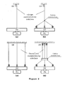
- FIGURES 2 /a, 2/b, 2/c and 2/d some possible solutions are presented for the pendulum-like suspension system composed at least in part of single or parallel cable segments. Solutions described in FIGURE 2 /b, 2/c and 2/d utilizing windable cables for the actuation of the roll and pitch of the payload platform, while concept in FIGURE 2 /a requires complementary actuators such as fans, gyros, etc.
- the primary design constraint is the amount of the required thrust.
- the nutation of the payload platform is proportional to the fluid mass flow generated, it should be maximized in order to provide a large working volume.
- the noise and the blow of the unit may become disturbing and the size/weight of the device may constrain the applicability of the whole system.
- FIGURE 3 /b six identical fluid mass flow generators are utilized. Considering these generators as ducted fans it is apparent that the thrust supplied by the smaller fans will be lower, however they provide better maneuverability for the suspended payload platform. This is because the special triangular arrangement of the fans that ensures closely uniform thrusting.
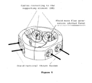
- FIGURE 4 shows the possible embodiment of a six fluid mass flow generator based design.
- the concept utilizes ducted fans as thrust source, since these devices have lower weight (and smaller size) compared to other solutions.
- the six fluid mass flow generator based concept by varying the performance of the individual fans, the generating moment can rotate the payload without the need of further actuators. Hence, this concept results in an easier solution for rotating the suspended payload platform and the payload.
- a three fluid mass flow generator based design (not part of the claimed invention) reaches a singular position. If the thrust force is not reversible, a small change of the position of the payload platform may require infinite angular accelerations. Reversing of the thrust may also be needed for the orientation of the payload platform when it hangs vertically down. In addition, the moment generated by the opposite direction thrust forces can be used to compensate for the inertial effects of the payload.
Landscapes
- Engineering & Computer Science (AREA)
- Mechanical Engineering (AREA)
- Structures Of Non-Positive Displacement Pumps (AREA)
Description
- The present invention relates to thrusting a payload platform suspended like a pendulum on a single cable or on parallel cables attached to a supporting element. The pendulum like suspension system may include complex multi-body or multi-cable sections but at least one section of it is limited to a single cable or parallel cables. In particular, and not by way of limitation, the present invention is directed to thrusting a payload platform of an aerial tethered robot or a suspended rescue system or a crane system.
- The concept of the aerial tethered system was inspired by deep sea marine robotics where a host ship uses a tethered robot to survey the site of a shipwreck and deploy tiny robotic agents from the tethered robot into an opening within the sunken vessel. This concept was applied to aerial systems.
- In
US-2007200027 patent publication an aerial robot is disclosed. The aerial robot may include at least one pair of counter-rotating blades or propellers, which may be contained within a circumferential shroud or a duct. The aerial robot may have the ability to hover and move indefinitely getting the electric power through a tether anchoring the robot to a ground station. The robot is suitable for remote observation, environment detection, communication, but due to the lifting force powered by fans not suitable for carrying heavy payloads. - A design of a tethered aerial robot is presented by P. J. McKerrow and D. Ratner originally published as: McKerrow, PJM & Ratner, D, The design of a tethered aerial robot, IEEE International Conference on Robotics and Automation 2007, Rome, Italy, 10-14 April 2007, 355-360. Copyright 2007 IEEE; in which the concept of a tethered aerial robot swinging on the end of a tether is described. In this approach the weight of the robot is carried by the tether and the thrusting force is generated by two fans with parallel axis. The critical issue in such suspended systems is the under-actuation of the suspended payload. The two ducted fans with parallel axes can only provide a one-directional thrust force and a resulting moment acting upon the suspended payload as independent control inputs. Thus, the number of actuators is lower than the degrees of freedom of the suspended payload.
- However the problem mentioned above can be extended to any payload platform suspended like a pendulum on single cable or on parallel cables and actuated by thrusting forces irrespective of the application in the technology, i.e., a suspended payload platform can be a part of a robotic system or that of a crane structure as well.
- Pendulum-like suspension systems that include single or parallel cables do not allow the actuation of the payload platform through the cables only. The required position and orientation of the payload can only be provided with the use of additional actuators, because of the pendulum-like behavior of these systems.
- We have set ourselves the objective with this invention to improve the thrusting of suspended payload platforms.
- Document
EP 0 806 775 Al relates to a method for movement correction and positioning of a suspension device. A correction device is arranged at the second end of the suspension device adapted to generate a force which provides acceleration in a fluid such that the position of the second end of the suspension device is corrected. The correction device is furnished with correction members (14, 16) that can be either propeller device (14) or nozzle means (16) for generating the force. In one embodiment two correction members (14, 18) (Fig. 2 ), in other embodiments (Fig 3 and 4) three or four correction members (14, 16) are used that are rotatable up to 360o. By use of rotatable correction members, force with any kind of horizontal direction can be applied, although direction of force generated by the correction members have to be controlled by e.g. a joystick (17). -
Document GB 2 141 088 A - Although in one embodiment of the document the helicopter units are multiplied (Fig. 13), the orientation of the payload is not provided.
- The present invention involves a new system which solves the aforementioned problems, as well as other problems that will become apparent from an understanding of the following description.
- The invention is based on the recognition that a payload platform suspended like a pendulum on single or parallel cables can only be controlled with serious limitations by a single direction thrust force or a pair of thrust forces. So the object of the invention is to provide a system of thrust forces of fluid mass flows for moving a payload platform the weight of which is compensated by pendulum-like single or parallel suspending cables attached to a suspending element. In the system of thrust forces the fluid mass flows are generated by at least six fluid mass flow generators each of them providing a force vector.
- Fluid mass flow generator is a system that determines the magnitude and the direction of the thrust force vector produced by emission of fluid or solid body particles. In particular, and not by way of limitation, fluid mass flow can be made by an axial or radial fan without or within a tube, nozzle with routed fluid mass flow from an external or on board compressor, nozzle with routed fluid mass flow from an external or on board fluid bottle, fluid storage tank. In particular, and not by way of limitation, for vectoring, including the reversing of the thrust produced by the previously listed systems, the source of thrust can be turned, deflectors including slewable nozzles or controlled valves can be used at the inlet (s) or outlet (s) of the source of the fluid mass flow, and variable blade pitch impellers can be applied.
- In a possible embodiment, a six fluid mass flow generator based design is described.
- In possible embodiments the fluid mass flow generators are fans, preferably ducted fans provided with reversible blade pitch impellers.
- With six mass flow generators, six lines of action of the thrust force vectors are coplanar, or are grouped into three pairs of parallel lines of action thrust force vectors that can be axis-symmetrical to the bisectors of an equilateral triangle.
- The most important advantage of the invention is that the payload platform suspended like a pendulum on single or parallel cables is fully actuated.
- In the following, the essential features of the invention will be described in detail by showing two preferred embodiments, with reference to the figures of the attached drawing.
-
FIGURE 1 shows a simplified model of the pendulum-like suspended payload platform. -
FIGURES 2 /a, 2/b, 2/c and 2/d present concepts for pendulum-like single and parallel cable based suspending systems. -
FIGURE 3 /b shows an arrangement of fluid mass flow generators (for simplicity modeled by ducted fans) and the supplied thrust force for six fluid mass flow generators. - FIGURE 4 shows a possible embodiment of a six fluid mass flow generator based design.
- As it is seen in
FIGURE 1 , the main operating functions that the pendulum-like suspended payload platform PP should provide are: compensating for the gravity by using single or parallel cables attached to the supporting element SE, and making thrust for controlling the position and orientation of the payload PL. - The swinging out of the payload is described by the nutation angle, while its polar displacement is described by the precession angle. In addition, turning the payload is characterized by the rotation angle about an axis fixed to the payload. The roll and pitch of the payload, e.g., and not by way of limitation, is to be set by additional fluid mass flow generators or by using windable orienting cables.
- The detailed analysis of the engineering systems and physical processes that fit the requirements has resulted in the mechanical and control related design principles for generating concepts for the pendulum-like suspended payload platform. It was found that for full actuation of the nutation, precession and rotation of the payload, a possible solution is the use of fluid mass flow generators such as ducted fans. In addition, it was concluded that auxiliary suspending cables can be used to compensate for the roll and pitch of the payload.
- In
FIGURES 2 /a, 2/b, 2/c and 2/d, some possible solutions are presented for the pendulum-like suspension system composed at least in part of single or parallel cable segments. Solutions described inFIGURE 2 /b, 2/c and 2/d utilizing windable cables for the actuation of the roll and pitch of the payload platform, while concept inFIGURE 2 /a requires complementary actuators such as fans, gyros, etc. - In case of the pendulum-like suspended payload platform, the primary design constraint is the amount of the required thrust. By seeing that the nutation of the payload platform is proportional to the fluid mass flow generated, it should be maximized in order to provide a large working volume. On the other hand, by increasing the fluid mass flow, the noise and the blow of the unit may become disturbing and the size/weight of the device may constrain the applicability of the whole system.
- Making and vectoring the thrust, and rotating the payload were analyzed in parallel to the two concepts with different (high and low) thrust requirements.
- In
FIGURE 3 /b six identical fluid mass flow generators are utilized. Considering these generators as ducted fans it is apparent that the thrust supplied by the smaller fans will be lower, however they provide better maneuverability for the suspended payload platform. This is because the special triangular arrangement of the fans that ensures closely uniform thrusting. - FIGURE 4 shows the possible embodiment of a six fluid mass flow generator based design.
- The concept utilizes ducted fans as thrust source, since these devices have lower weight (and smaller size) compared to other solutions.
- The six fluid mass flow generator based concept, by varying the performance of the individual fans, the generating moment can rotate the payload without the need of further actuators. Hence, this concept results in an easier solution for rotating the suspended payload platform and the payload.
- When the payload platform is to be stopped in a hanging down position (at zero nutation), a three fluid mass flow generator based design (not part of the claimed invention) reaches a singular position. If the thrust force is not reversible, a small change of the position of the payload platform may require infinite angular accelerations. Reversing of the thrust may also be needed for the orientation of the payload platform when it hangs vertically down. In addition, the moment generated by the opposite direction thrust forces can be used to compensate for the inertial effects of the payload.
- According to the above considerations, it can be concluded that a design concept based on three fluid mass flow generators should incorporate two ducted fans arranged in parallel and a complementary ducted fan with transversal air mass flow, while the thrusting forces should be reversible at all ducted fans. However, with six fluid mass flow generators, the role of the fluid mass flow generators cannot be separated. They are identical to each other and contribute to the thrusting and turning of the payload platform equally.
- Although preferred embodiments of the present invention have been illustrated in the accompanying Drawings and described in the foregoing Detailed Description, it is understood that the invention is not limited to the embodiments disclosed and to the use of ducted fans as fluid mass flow generators, but is capable of numerous rearrangements, modifications, and substitutions without departing from the concept of the invention as set forth and defined by the following claims.
Claims (3)
- A payload platform (PP) the weight of which is compensated by suspension system connected to a suspending element and thrusted by fluid mass flows;- the suspension system is composed in part or in whole of single or parallel suspending cable segments,- the fluid mass flows are generated by flow generators implemented as fans,- each of the fluid mass flow generators provides a thrust force vector (FT),
characterized in that,- at least six fluid mass flow generators are implemented, the- line of action of each thrust force vector (FT) in respect to the payload platform (PP) is coplanar to the other thrust force vectors (FT) that are grouped by three pairs of parallel lines of action, and- the parallel lines of action of the three pairs of the thrust force vectors (FT) are axis-symmetrical to the perpendicular bisectors of the sides of an equilateral triangle. - The payload platform of claim 1 characterized in that, the fans are six ducted fans.
- The payload platform of claim 1 characterized in that the fluid mass flow generators are adapted to control the rotation of the payload platform.
Applications Claiming Priority (2)
| Application Number | Priority Date | Filing Date | Title |
|---|---|---|---|
| HU0900467A HUP0900467A2 (en) | 2009-07-28 | 2009-07-28 | Suspended payload platform thrusted by fluid mass flow generators |
| PCT/HU2010/000084 WO2011012915A1 (en) | 2009-07-28 | 2010-07-27 | Suspended payload platform thrusted by fluid mass flow generators |
Publications (2)
| Publication Number | Publication Date |
|---|---|
| EP2480478A1 EP2480478A1 (en) | 2012-08-01 |
| EP2480478B1 true EP2480478B1 (en) | 2014-12-17 |
Family
ID=89989140
Family Applications (1)
| Application Number | Title | Priority Date | Filing Date |
|---|---|---|---|
| EP10749902.2A Not-in-force EP2480478B1 (en) | 2009-07-28 | 2010-07-27 | Suspended payload platform thrusted by fluid mass flow generators |
Country Status (3)
| Country | Link |
|---|---|
| EP (1) | EP2480478B1 (en) |
| HU (1) | HUP0900467A2 (en) |
| WO (1) | WO2011012915A1 (en) |
Families Citing this family (15)
| Publication number | Priority date | Publication date | Assignee | Title |
|---|---|---|---|---|
| US11945697B2 (en) | 2018-02-08 | 2024-04-02 | Vita Inclinata Ip Holdings Llc | Multiple remote control for suspended load control equipment apparatus, system, and method |
| US11209836B1 (en) | 2018-02-08 | 2021-12-28 | Vita Inclinata Technologies, Inc. | Long line loiter apparatus, system, and method |
| US12304779B2 (en) | 2018-02-08 | 2025-05-20 | Vita Inclinata Ip Holdings Llc | On-board power and remote power for suspended load control apparatuses, systems, and methods |
| US12246952B2 (en) | 2018-02-08 | 2025-03-11 | Vita Inclintata IP Holdings LLC | Hoist and deployable equipment apparatus, system, and method |
| US11142316B2 (en) | 2018-02-08 | 2021-10-12 | Vita Inclinata Technologies, Inc. | Control of drone-load system method, system, and apparatus |
| US12434813B2 (en) | 2018-02-08 | 2025-10-07 | Vita Inclinata Ip Holdings Llc | Bidirectional thrust apparatus, system and method |
| PE20191527Z (en) | 2018-02-08 | 2019-10-23 | Vita Inclinata Tech Inc | SUSPENDED LOAD STABILITY SYSTEMS AND METHODS |
| WO2020176665A1 (en) | 2019-02-26 | 2020-09-03 | Vita Inclinata Technologies, Inc. | Cable deployment apparatus, system, and methods for suspended load control equipment |
| US11834305B1 (en) | 2019-04-12 | 2023-12-05 | Vita Inclinata Ip Holdings Llc | Apparatus, system, and method to control torque or lateral thrust applied to a load suspended on a suspension cable |
| WO2025122161A1 (en) | 2023-12-04 | 2025-06-12 | Vita Inclinata Ip Holdings Llc | Apparatus, system, and method to control torque or lateral thrust applied to a load suspended on a suspension cable |
| US11618566B1 (en) | 2019-04-12 | 2023-04-04 | Vita Inclinata Technologies, Inc. | State information and telemetry for suspended load control equipment apparatus, system, and method |
| EP3778393B2 (en) | 2019-08-13 | 2025-04-02 | AIRBUS HELICOPTERS DEUTSCHLAND GmbH | A load carrying assembly |
| EP4065468B1 (en) | 2019-11-25 | 2025-05-07 | Vita Inclinata IP Holdings LLC | Method and apparatus for control of a suspended load |
| US11873099B2 (en) | 2020-12-02 | 2024-01-16 | Airbus Helicopters Deutschland GmbH | Load carrying assembly |
| WO2023211499A1 (en) | 2022-04-29 | 2023-11-02 | Vita Inclinata Ip Holdings Llc | Machine learning real property object detection and analysis apparatus, system, and method |
Family Cites Families (5)
| Publication number | Priority date | Publication date | Assignee | Title |
|---|---|---|---|---|
| US4601444A (en) * | 1983-06-08 | 1986-07-22 | Bernard Lindenbaum | Aerial load-lifting system |
| JPH04256686A (en) * | 1991-02-06 | 1992-09-11 | Ishikawajima Harima Heavy Ind Co Ltd | Suspending device |
| SE506569C2 (en) * | 1996-05-10 | 1998-01-12 | Asea Atom Ab | Method and apparatus for motion correction and positioning of a suspension device |
| NO316438B1 (en) * | 2001-08-31 | 2004-01-26 | Lars Magnus Solstad | Remote controlled connection device for lifting device |
| US7510142B2 (en) | 2006-02-24 | 2009-03-31 | Stealth Robotics | Aerial robot |
-
2009
- 2009-07-28 HU HU0900467A patent/HUP0900467A2/en unknown
-
2010
- 2010-07-27 WO PCT/HU2010/000084 patent/WO2011012915A1/en not_active Ceased
- 2010-07-27 EP EP10749902.2A patent/EP2480478B1/en not_active Not-in-force
Also Published As
| Publication number | Publication date |
|---|---|
| HU0900467D0 (en) | 2009-09-28 |
| EP2480478A1 (en) | 2012-08-01 |
| HUP0900467A2 (en) | 2011-06-28 |
| WO2011012915A1 (en) | 2011-02-03 |
Similar Documents
| Publication | Publication Date | Title |
|---|---|---|
| WO2011012915A1 (en) | Suspended payload platform thrusted by fluid mass flow generators | |
| JP7766953B2 (en) | System and method for stabilizing suspended loads | |
| US12172752B2 (en) | Control of drone-load system method, system, and apparatus | |
| EP3999463B1 (en) | Hoist and deployable equipment apparatus, system, and method | |
| CN115135579B (en) | Connectors for floating load control devices, systems, and methods | |
| US11142433B2 (en) | Bidirectional thrust apparatus, system, and method | |
| EP4065461B1 (en) | Bidirectional thrust apparatus, system, and method | |
| US20250197169A1 (en) | Hoist and deployable equipment apparatus, system, and method | |
| US12434813B2 (en) | Bidirectional thrust apparatus, system and method | |
| US20170253329A1 (en) | Six degree of freedom aerial vehicle | |
| JP6508331B2 (en) | Moving body | |
| US5070955A (en) | Passively stable hovering system | |
| US20220033080A1 (en) | A payload control device | |
| KR20230133301A (en) | Systems and methods for payload stabilization | |
| RU165676U1 (en) | UAV VERTICAL TAKEOFF AND LANDING | |
| EP3583028B1 (en) | Maintaining attitude control of unmanned aerial vehicles | |
| JP4628994B2 (en) | Airship type aerial crane | |
| CN116215868B (en) | Cable-suspended aerial manipulator system and working method thereof | |
| WO2017140250A1 (en) | Aircraft | |
| HK30074355A2 (en) | Suspended load stability systems and non-transitory computer-readable storage medium |
Legal Events
| Date | Code | Title | Description |
|---|---|---|---|
| PUAI | Public reference made under article 153(3) epc to a published international application that has entered the european phase |
Free format text: ORIGINAL CODE: 0009012 |
|
| 17P | Request for examination filed |
Effective date: 20120613 |
|
| AK | Designated contracting states |
Kind code of ref document: A1 Designated state(s): AL AT BE BG CH CY CZ DE DK EE ES FI FR GB GR HR HU IE IS IT LI LT LU LV MC MK MT NL NO PL PT RO SE SI SK SM TR |
|
| DAX | Request for extension of the european patent (deleted) | ||
| 17Q | First examination report despatched |
Effective date: 20130307 |
|
| GRAP | Despatch of communication of intention to grant a patent |
Free format text: ORIGINAL CODE: EPIDOSNIGR1 |
|
| INTG | Intention to grant announced |
Effective date: 20140320 |
|
| RIN1 | Information on inventor provided before grant (corrected) |
Inventor name: JURAK, MIHALY Inventor name: TOTH , ANDRAS Inventor name: BACHRATHY, DANIEL Inventor name: WOHLFART, RICHARD Inventor name: KOVACS, LASZLO Inventor name: STEPAN, GABOR |
|
| GRAS | Grant fee paid |
Free format text: ORIGINAL CODE: EPIDOSNIGR3 |
|
| GRAA | (expected) grant |
Free format text: ORIGINAL CODE: 0009210 |
|
| AK | Designated contracting states |
Kind code of ref document: B1 Designated state(s): AL AT BE BG CH CY CZ DE DK EE ES FI FR GB GR HR HU IE IS IT LI LT LU LV MC MK MT NL NO PL PT RO SE SI SK SM TR |
|
| REG | Reference to a national code |
Ref country code: GB Ref legal event code: FG4D |
|
| REG | Reference to a national code |
Ref country code: CH Ref legal event code: EP |
|
| REG | Reference to a national code |
Ref country code: IE Ref legal event code: FG4D |
|
| REG | Reference to a national code |
Ref country code: AT Ref legal event code: REF Ref document number: 701729 Country of ref document: AT Kind code of ref document: T Effective date: 20150115 |
|
| REG | Reference to a national code |
Ref country code: DE Ref legal event code: R096 Ref document number: 602010021087 Country of ref document: DE Effective date: 20150212 |
|
| PG25 | Lapsed in a contracting state [announced via postgrant information from national office to epo] |
Ref country code: FI Free format text: LAPSE BECAUSE OF FAILURE TO SUBMIT A TRANSLATION OF THE DESCRIPTION OR TO PAY THE FEE WITHIN THE PRESCRIBED TIME-LIMIT Effective date: 20141217 Ref country code: LT Free format text: LAPSE BECAUSE OF FAILURE TO SUBMIT A TRANSLATION OF THE DESCRIPTION OR TO PAY THE FEE WITHIN THE PRESCRIBED TIME-LIMIT Effective date: 20141217 Ref country code: NO Free format text: LAPSE BECAUSE OF FAILURE TO SUBMIT A TRANSLATION OF THE DESCRIPTION OR TO PAY THE FEE WITHIN THE PRESCRIBED TIME-LIMIT Effective date: 20150317 |
|
| REG | Reference to a national code |
Ref country code: LT Ref legal event code: MG4D |
|
| PG25 | Lapsed in a contracting state [announced via postgrant information from national office to epo] |
Ref country code: LV Free format text: LAPSE BECAUSE OF FAILURE TO SUBMIT A TRANSLATION OF THE DESCRIPTION OR TO PAY THE FEE WITHIN THE PRESCRIBED TIME-LIMIT Effective date: 20141217 Ref country code: SE Free format text: LAPSE BECAUSE OF FAILURE TO SUBMIT A TRANSLATION OF THE DESCRIPTION OR TO PAY THE FEE WITHIN THE PRESCRIBED TIME-LIMIT Effective date: 20141217 Ref country code: GR Free format text: LAPSE BECAUSE OF FAILURE TO SUBMIT A TRANSLATION OF THE DESCRIPTION OR TO PAY THE FEE WITHIN THE PRESCRIBED TIME-LIMIT Effective date: 20150318 Ref country code: HR Free format text: LAPSE BECAUSE OF FAILURE TO SUBMIT A TRANSLATION OF THE DESCRIPTION OR TO PAY THE FEE WITHIN THE PRESCRIBED TIME-LIMIT Effective date: 20141217 |
|
| REG | Reference to a national code |
Ref country code: AT Ref legal event code: MK05 Ref document number: 701729 Country of ref document: AT Kind code of ref document: T Effective date: 20141217 |
|
| PG25 | Lapsed in a contracting state [announced via postgrant information from national office to epo] |
Ref country code: NL Free format text: LAPSE BECAUSE OF FAILURE TO SUBMIT A TRANSLATION OF THE DESCRIPTION OR TO PAY THE FEE WITHIN THE PRESCRIBED TIME-LIMIT Effective date: 20141217 |
|
| PG25 | Lapsed in a contracting state [announced via postgrant information from national office to epo] |
Ref country code: RO Free format text: LAPSE BECAUSE OF FAILURE TO SUBMIT A TRANSLATION OF THE DESCRIPTION OR TO PAY THE FEE WITHIN THE PRESCRIBED TIME-LIMIT Effective date: 20141217 Ref country code: SK Free format text: LAPSE BECAUSE OF FAILURE TO SUBMIT A TRANSLATION OF THE DESCRIPTION OR TO PAY THE FEE WITHIN THE PRESCRIBED TIME-LIMIT Effective date: 20141217 Ref country code: ES Free format text: LAPSE BECAUSE OF FAILURE TO SUBMIT A TRANSLATION OF THE DESCRIPTION OR TO PAY THE FEE WITHIN THE PRESCRIBED TIME-LIMIT Effective date: 20141217 Ref country code: EE Free format text: LAPSE BECAUSE OF FAILURE TO SUBMIT A TRANSLATION OF THE DESCRIPTION OR TO PAY THE FEE WITHIN THE PRESCRIBED TIME-LIMIT Effective date: 20141217 Ref country code: CZ Free format text: LAPSE BECAUSE OF FAILURE TO SUBMIT A TRANSLATION OF THE DESCRIPTION OR TO PAY THE FEE WITHIN THE PRESCRIBED TIME-LIMIT Effective date: 20141217 |
|
| PG25 | Lapsed in a contracting state [announced via postgrant information from national office to epo] |
Ref country code: PL Free format text: LAPSE BECAUSE OF FAILURE TO SUBMIT A TRANSLATION OF THE DESCRIPTION OR TO PAY THE FEE WITHIN THE PRESCRIBED TIME-LIMIT Effective date: 20141217 Ref country code: AT Free format text: LAPSE BECAUSE OF FAILURE TO SUBMIT A TRANSLATION OF THE DESCRIPTION OR TO PAY THE FEE WITHIN THE PRESCRIBED TIME-LIMIT Effective date: 20141217 Ref country code: IS Free format text: LAPSE BECAUSE OF FAILURE TO SUBMIT A TRANSLATION OF THE DESCRIPTION OR TO PAY THE FEE WITHIN THE PRESCRIBED TIME-LIMIT Effective date: 20150417 |
|
| REG | Reference to a national code |
Ref country code: DE Ref legal event code: R097 Ref document number: 602010021087 Country of ref document: DE |
|
| PLBE | No opposition filed within time limit |
Free format text: ORIGINAL CODE: 0009261 |
|
| STAA | Information on the status of an ep patent application or granted ep patent |
Free format text: STATUS: NO OPPOSITION FILED WITHIN TIME LIMIT |
|
| PG25 | Lapsed in a contracting state [announced via postgrant information from national office to epo] |
Ref country code: DK Free format text: LAPSE BECAUSE OF FAILURE TO SUBMIT A TRANSLATION OF THE DESCRIPTION OR TO PAY THE FEE WITHIN THE PRESCRIBED TIME-LIMIT Effective date: 20141217 |
|
| 26N | No opposition filed |
Effective date: 20150918 |
|
| PG25 | Lapsed in a contracting state [announced via postgrant information from national office to epo] |
Ref country code: IT Free format text: LAPSE BECAUSE OF FAILURE TO SUBMIT A TRANSLATION OF THE DESCRIPTION OR TO PAY THE FEE WITHIN THE PRESCRIBED TIME-LIMIT Effective date: 20141217 |
|
| REG | Reference to a national code |
Ref country code: DE Ref legal event code: R119 Ref document number: 602010021087 Country of ref document: DE |
|
| PG25 | Lapsed in a contracting state [announced via postgrant information from national office to epo] |
Ref country code: MC Free format text: LAPSE BECAUSE OF FAILURE TO SUBMIT A TRANSLATION OF THE DESCRIPTION OR TO PAY THE FEE WITHIN THE PRESCRIBED TIME-LIMIT Effective date: 20141217 Ref country code: SI Free format text: LAPSE BECAUSE OF FAILURE TO SUBMIT A TRANSLATION OF THE DESCRIPTION OR TO PAY THE FEE WITHIN THE PRESCRIBED TIME-LIMIT Effective date: 20141217 |
|
| REG | Reference to a national code |
Ref country code: CH Ref legal event code: PL |
|
| GBPC | Gb: european patent ceased through non-payment of renewal fee |
Effective date: 20150727 |
|
| PG25 | Lapsed in a contracting state [announced via postgrant information from national office to epo] |
Ref country code: LU Free format text: LAPSE BECAUSE OF FAILURE TO SUBMIT A TRANSLATION OF THE DESCRIPTION OR TO PAY THE FEE WITHIN THE PRESCRIBED TIME-LIMIT Effective date: 20150727 |
|
| REG | Reference to a national code |
Ref country code: IE Ref legal event code: MM4A |
|
| PG25 | Lapsed in a contracting state [announced via postgrant information from national office to epo] |
Ref country code: LI Free format text: LAPSE BECAUSE OF NON-PAYMENT OF DUE FEES Effective date: 20150731 Ref country code: CH Free format text: LAPSE BECAUSE OF NON-PAYMENT OF DUE FEES Effective date: 20150731 Ref country code: GB Free format text: LAPSE BECAUSE OF NON-PAYMENT OF DUE FEES Effective date: 20150727 Ref country code: DE Free format text: LAPSE BECAUSE OF NON-PAYMENT OF DUE FEES Effective date: 20160202 |
|
| REG | Reference to a national code |
Ref country code: FR Ref legal event code: ST Effective date: 20160331 |
|
| PG25 | Lapsed in a contracting state [announced via postgrant information from national office to epo] |
Ref country code: FR Free format text: LAPSE BECAUSE OF NON-PAYMENT OF DUE FEES Effective date: 20150731 Ref country code: BE Free format text: LAPSE BECAUSE OF FAILURE TO SUBMIT A TRANSLATION OF THE DESCRIPTION OR TO PAY THE FEE WITHIN THE PRESCRIBED TIME-LIMIT Effective date: 20141217 |
|
| PG25 | Lapsed in a contracting state [announced via postgrant information from national office to epo] |
Ref country code: IE Free format text: LAPSE BECAUSE OF NON-PAYMENT OF DUE FEES Effective date: 20150727 |
|
| PG25 | Lapsed in a contracting state [announced via postgrant information from national office to epo] |
Ref country code: MT Free format text: LAPSE BECAUSE OF FAILURE TO SUBMIT A TRANSLATION OF THE DESCRIPTION OR TO PAY THE FEE WITHIN THE PRESCRIBED TIME-LIMIT Effective date: 20141217 |
|
| PG25 | Lapsed in a contracting state [announced via postgrant information from national office to epo] |
Ref country code: BG Free format text: LAPSE BECAUSE OF FAILURE TO SUBMIT A TRANSLATION OF THE DESCRIPTION OR TO PAY THE FEE WITHIN THE PRESCRIBED TIME-LIMIT Effective date: 20141217 Ref country code: SM Free format text: LAPSE BECAUSE OF FAILURE TO SUBMIT A TRANSLATION OF THE DESCRIPTION OR TO PAY THE FEE WITHIN THE PRESCRIBED TIME-LIMIT Effective date: 20141217 Ref country code: HU Free format text: LAPSE BECAUSE OF FAILURE TO SUBMIT A TRANSLATION OF THE DESCRIPTION OR TO PAY THE FEE WITHIN THE PRESCRIBED TIME-LIMIT; INVALID AB INITIO Effective date: 20100727 |
|
| PG25 | Lapsed in a contracting state [announced via postgrant information from national office to epo] |
Ref country code: CY Free format text: LAPSE BECAUSE OF FAILURE TO SUBMIT A TRANSLATION OF THE DESCRIPTION OR TO PAY THE FEE WITHIN THE PRESCRIBED TIME-LIMIT Effective date: 20141217 |
|
| PG25 | Lapsed in a contracting state [announced via postgrant information from national office to epo] |
Ref country code: TR Free format text: LAPSE BECAUSE OF FAILURE TO SUBMIT A TRANSLATION OF THE DESCRIPTION OR TO PAY THE FEE WITHIN THE PRESCRIBED TIME-LIMIT Effective date: 20141217 |
|
| PG25 | Lapsed in a contracting state [announced via postgrant information from national office to epo] |
Ref country code: MK Free format text: LAPSE BECAUSE OF FAILURE TO SUBMIT A TRANSLATION OF THE DESCRIPTION OR TO PAY THE FEE WITHIN THE PRESCRIBED TIME-LIMIT Effective date: 20141217 |
|
| PG25 | Lapsed in a contracting state [announced via postgrant information from national office to epo] |
Ref country code: PT Free format text: LAPSE BECAUSE OF FAILURE TO SUBMIT A TRANSLATION OF THE DESCRIPTION OR TO PAY THE FEE WITHIN THE PRESCRIBED TIME-LIMIT Effective date: 20141217 |
|
| PG25 | Lapsed in a contracting state [announced via postgrant information from national office to epo] |
Ref country code: AL Free format text: LAPSE BECAUSE OF FAILURE TO SUBMIT A TRANSLATION OF THE DESCRIPTION OR TO PAY THE FEE WITHIN THE PRESCRIBED TIME-LIMIT Effective date: 20141217 |