EP2480378B1 - Dispositif de distribution de jets de fluide cryogénique avec joint en polymère à coefficient de dilatation donné - Google Patents
Dispositif de distribution de jets de fluide cryogénique avec joint en polymère à coefficient de dilatation donné Download PDFInfo
- Publication number
- EP2480378B1 EP2480378B1 EP10773118.4A EP10773118A EP2480378B1 EP 2480378 B1 EP2480378 B1 EP 2480378B1 EP 10773118 A EP10773118 A EP 10773118A EP 2480378 B1 EP2480378 B1 EP 2480378B1
- Authority
- EP
- European Patent Office
- Prior art keywords
- fluid
- cryogenic
- seal
- tool
- dispensing
- Prior art date
- Legal status (The legal status is an assumption and is not a legal conclusion. Google has not performed a legal analysis and makes no representation as to the accuracy of the status listed.)
- Not-in-force
Links
Images

Classifications
-
- B—PERFORMING OPERATIONS; TRANSPORTING
- B05—SPRAYING OR ATOMISING IN GENERAL; APPLYING FLUENT MATERIALS TO SURFACES, IN GENERAL
- B05B—SPRAYING APPARATUS; ATOMISING APPARATUS; NOZZLES
- B05B13/00—Machines or plants for applying liquids or other fluent materials to surfaces of objects or other work by spraying, not covered by groups B05B1/00 - B05B11/00
- B05B13/02—Means for supporting work; Arrangement or mounting of spray heads; Adaptation or arrangement of means for feeding work
- B05B13/04—Means for supporting work; Arrangement or mounting of spray heads; Adaptation or arrangement of means for feeding work the spray heads being moved during spraying operation
- B05B13/0421—Means for supporting work; Arrangement or mounting of spray heads; Adaptation or arrangement of means for feeding work the spray heads being moved during spraying operation with rotating spray heads
-
- B—PERFORMING OPERATIONS; TRANSPORTING
- B24—GRINDING; POLISHING
- B24C—ABRASIVE OR RELATED BLASTING WITH PARTICULATE MATERIAL
- B24C1/00—Methods for use of abrasive blasting for producing particular effects; Use of auxiliary equipment in connection with such methods
- B24C1/003—Methods for use of abrasive blasting for producing particular effects; Use of auxiliary equipment in connection with such methods using material which dissolves or changes phase after the treatment, e.g. ice, CO2
-
- B—PERFORMING OPERATIONS; TRANSPORTING
- B24—GRINDING; POLISHING
- B24C—ABRASIVE OR RELATED BLASTING WITH PARTICULATE MATERIAL
- B24C3/00—Abrasive blasting machines or devices; Plants
- B24C3/02—Abrasive blasting machines or devices; Plants characterised by the arrangement of the component assemblies with respect to each other
- B24C3/04—Abrasive blasting machines or devices; Plants characterised by the arrangement of the component assemblies with respect to each other stationary
-
- B—PERFORMING OPERATIONS; TRANSPORTING
- B05—SPRAYING OR ATOMISING IN GENERAL; APPLYING FLUENT MATERIALS TO SURFACES, IN GENERAL
- B05B—SPRAYING APPARATUS; ATOMISING APPARATUS; NOZZLES
- B05B1/00—Nozzles, spray heads or other outlets, with or without auxiliary devices such as valves, heating means
- B05B1/14—Nozzles, spray heads or other outlets, with or without auxiliary devices such as valves, heating means with multiple outlet openings; with strainers in or outside the outlet opening
-
- B—PERFORMING OPERATIONS; TRANSPORTING
- B05—SPRAYING OR ATOMISING IN GENERAL; APPLYING FLUENT MATERIALS TO SURFACES, IN GENERAL
- B05B—SPRAYING APPARATUS; ATOMISING APPARATUS; NOZZLES
- B05B15/00—Details of spraying plant or spraying apparatus not otherwise provided for; Accessories
- B05B15/60—Arrangements for mounting, supporting or holding spraying apparatus
- B05B15/65—Mounting arrangements for fluid connection of the spraying apparatus or its outlets to flow conduits
Definitions
- the invention relates to a device and a method for working by jets of cryogenic fluid under high pressure, in particular surface treatment, pickling or peeling, comprising a rotary joint with a given coefficient of expansion and coefficient of friction.
- cryogenic jets under very high pressure as proposed for example by the documents US Patent 7,310,955 and US Patent 7,316,363 to perform surface treatments of coated or uncoated materials, in particular pickling, peeling or the like, or even cutting such as metals, concrete, wood, polymers, ceramics and plastics or any other type of material.
- This type of process is intended to be implemented in particular in environments where there are drastic environmental constraints, such as in nuclear and chemical environments.
- the jetting or jets of liquid nitrogen at a pressure of 1000 to 4000 bar and at a cryogenic temperature of, for example, between -100 and -200 ° C., typically about -140 and -160 ° C., are distributed by a nozzle-carrying tool. which can be fixed or animated with a rotary or oscillating movement, and which is generally supplied with liquid nitrogen by a cryogenic fluid supply line.
- the pipe and the tool are given a rotary movement about the axis of the pipe, by means of a rotary drive system with pinions or belts driven by a engine.
- the dynamic sealing of the rotary system is usually provided by a rotating cylindrical seal, typically Tivar®, arranged around the pipe, longitudinally traversed by a bronze piece and surrounded by a solid piece of stainless steel.
- a rotating cylindrical seal typically Tivar®
- the problem to be solved is therefore to increase the reliability of a cryogenic fluid distribution system, in particular of liquid nitrogen, as described above, by proposing a distribution system with fluid distribution tool with seal rotative improved to overcome the aforementioned drawbacks.
- the invention also relates to an installation for dispensing at least one cryogenic fluid jet under high pressure comprising a device according to the invention supplied with cryogenic fluid by a source of cryogenic temperature fluid and comprising a rotating tool equipped with one or more nozzles for dispensing said cryogenic fluid under pressure.
- the invention also relates to a method for surface treatment, pickling or peeling, a material by jets of cryogenic fluid at high pressure, in which an installation or a device according to the invention is used. invention.
- the cryogenic fluid dispensed by the nozzle (s) of the tool is at a pressure of at least 500 bar, preferably between 2000 and 4000 bar.
- the fluid dispensed by the nozzle or nozzles of the tool is at a temperature below -140 ° C, preferably between about -140 and -180 ° C.
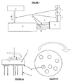
- the Figure 1 is a schematic view (side view) of the portion of a cryogenic temperature and high pressure fluid jet dispenser 6 showing the seal of the rotary system 1 and the rotary tool 3. More precisely , the cylindrical seal 20 is arranged at the intersection of the portions 2, 5 of the pipeline carrying the liquid nitrogen (LN 2 ) and is traversed longitudinally by one or more bronze pieces 22, 23 and is surrounded by a massive piece in stainless steel 21. The seal 20 provides dynamic sealing of the rotary system 1 since the upstream portion 5 is fixed, while the downstream portion 2 is rotatable.
- LN 2 liquid nitrogen
- the cylindrical rotating seal is a seal of polymeric material having a coefficient of thermal expansion of between 10 ⁇ 10 -6 and 160 ⁇ 10 -6 / K, preferably between about 20 ⁇ 10 -6 and about 130 ⁇ 10 -6 / K. These values are valid and assumed to be constant for the considered temperature range.
- the coefficients of linear thermal expansion are obtained in accordance with DIN 50044.
- Table II below gives the coefficients of thermal expansion, on the one hand, of Tivar® and, on the other hand, of several commercially available polymers which can be used as a seal in the system of the Figure 1 and thus advantageously replace the Tivar® seals conventionally used in a cryogenic medium.
- Table II Coefficient of thermal expansion (x10 -6 / K) PTFE PCTFE PAI PPS UHMW PE Teflon® Kel'F® Voltalef® Torlon Ryton® Tivar® 120 70 30 22 180
- UHMW PE Very high molecular weight polyethylene.
- the values in Table II are valid and assumed to be constant for the temperature range considered.
- the coefficients of linear thermal expansion are obtained in accordance with DIN 50044.
- PTFE, PCTFE, PAI and PPS have low friction coefficients of the same order as Tivar ®.
- the polymers PS and PAI are the materials which are best suited to manufacture the rotary joint according to the invention.
- the other two polymers are also suitable although less preferred.
- the reliability of the cryogenic fluid distribution system can be increased, that is to say, avoid or minimize the progressive appearance of a clearance between the seal 20 and the metal parts 21, 22, 23 of the rotary system 1, and thus avoid or minimize nitrogen leakage at said seal 20.
- FIG. 3 there is shown on the Figure 3 , an installation equipped with a device provided with a gasket according to the invention, for example usable for carrying out surface etching by jets 6 of cryogenic liquid.
- This installation consists of a storage tank 11, such as a tank, of liquid nitrogen (hereinafter referred to as LN 2 ) which feeds, via a supply line 16 of liquid nitrogen under low pressure, that is, that is to say at about 3 to 6 bar and at a temperature of the order of -180 ° C, a compression device 12, with compressor and internal upstream heat exchanger for ultra high pressure (UHP) setting of the liquid nitrogen.
- LN 2 liquid nitrogen
- UHP ultra high pressure
- LN 2 at the first pressure (UHP) is then conveyed via a conveyor line 17, to an external downstream heat exchanger 13 where the LN2 UHP undergoes cooling with liquid nitrogen at atmospheric pressure (at 9), to typically obtain UHP liquid nitrogen.
- LN 2 at a pressure (UHP) typically greater than 1000 bar, generally between 2000 bar and 5000 bar, advantageously between about 3000 and 4000 bar, and at a temperature below -140 ° C., typically between about -140 ° C and -180 ° C, for example of the order of about -150 to -160 ° C, which is sent via the portions of lines 5, 2, to the rotary pickling tool 4 or the like provided with dispensing nozzles 18 delivering jets 6 of liquid nitrogen UHP.
- UHP pressure
- the high-capacity fixed or mobile tank 11 such as a truck tank or a storage tank of several thousand liters of liquid nitrogen, is generally located outside the buildings, that is to say at the outdoors.
- the tank 11 is connected to the installation by means of insulated pipes comprising one or more control valves.
- the LN 2 conveying between the various elements of the system is also done via insulated pipes.
- the overall gas flow is approximately 20 l / min or 15 m 3 / min.
- the compression device 12, the external exchanger 13 and especially the tool 4 are in principle located in one or more buildings.
- the rotation of the downstream portion 2 of the pipe and the tool 3 is obtained by means of a conventional drive system with motor and sprockets or drive belts.
- a heat treatment device equipped with a seal according to the present invention is applicable in any operation or heat treatment process requiring the implementation of a rotation or oscillation of cryogenic fluid jets, in particular surface treatment, pickling or of a material, such as metals, concrete, stone, plastics, wood, ceramics ...
Landscapes
- Engineering & Computer Science (AREA)
- Mechanical Engineering (AREA)
- Joints Allowing Movement (AREA)
- Filling Or Discharging Of Gas Storage Vessels (AREA)
- Quick-Acting Or Multi-Walled Pipe Joints (AREA)
- Perforating, Stamping-Out Or Severing By Means Other Than Cutting (AREA)
Description
- L'invention porte sur un dispositif et un procédé de travail par jets de fluide cryogénique sous haute pression, en particulier de traitement de surface, de décapage ou d'écroutage, comprenant un joint rotatif à coefficient de dilatation et coefficient de frottement donnés.
- Il est connu d'utiliser un ou des jets cryogéniques sous très haute pression comme proposé par exemple par les documents
US-A-7,310,955 etUS-A-7,316,363 pour opérer des traitements de surface de matériaux revêtus ou non, en particulier le décapage, l'écroutage ou analogue, voire des découpages, tels les métaux, le béton, le bois, les polymères, les céramiques et les plastiques ou tout autre type de matériau. - Ce type de procédé est destiné à être mis en oeuvre notamment dans les milieux où existent des contraintes environnementales drastiques, tel que dans les milieux nucléaire et chimique.
- Le ou les jets d'azote liquide à une pression de 1000 à 4000 bars et à température cryogénique comprise par exemple entre -100 et -200°C, typiquement environ -140 et -160°C, sont distribués par un outil porte-buses qui peut être fixé ou animé d'un mouvement rotatif ou oscillant, et qui est généralement alimenté en azote liquide par une canalisation d'amenée de fluide cryogénique.
- Pour obtenir un mouvement rotatif de l'outil, on confère à la canalisation et à l'outil, un mouvement rotatif autour de l'axe de la canalisation, au moyen d'un système rotatif d'entraînement à pignons ou courroies mus par un moteur.
- L'étanchéité dynamique du système rotatif est habituellement assurée par un joint cylindrique tournant, typiquement en Tivar®, agencé autour de la canalisation, traversé longitudinalement par une pièce en bronze et entouré par une pièce massive en acier inoxydable.
- Du fait des températures cryogéniques mises en oeuvre, typiquement inférieures à environ -150°C, on a remarqué en pratique que l'efficacité de ce joint diminue au fil du temps, ce qui engendre à plus ou moins courte échéance des fuites et donc des pertes de rendement du procédé, notamment lors d'opérations d'écroutage de béton ou de décapage de peinture par exemple.
- En effet, sous l'effet des températures cryogéniques mises en oeuvre, les matériaux se déforment de manière différente les uns des autres, en fonction de leur coefficient de dilatation thermique respectif, comme illustré dans le Tableau I.
Tableau I Coefficient de dilatation thermique (x 10-6/K) Tivar®* Acier inoxydable 316 Bronze 180 15 (NIST = 24) 17.5 *Le Tivar® est un polyéthylène à très grand poids moléculaire. - Ces valeurs sont valables et supposées constantes pour la plage de températures considérée. Les coefficients de dilatation thermique linéique sont obtenus conformément à la norme DIN 50044.
- Comme on le voit, ces matériaux réagissent très différemment aux températures cryogéniques et, de ce fait, au cours des cycles alternatifs de refroidissement et de réchauffement, il se produit des déformations, voire des détériorations du joint et ce, d'autant plus rapidement qu'il est soumis à des pressions très importantes, à savoir jusqu'à typiquement 4000 bars.
- En effet, on a constaté en pratique qu'un jeu apparaît progressivement entre le joint et les pièces métalliques, lequel induit des fuites, qui sont rédhibitoires pour un fonctionnement normal du système. En conséquence de quoi, il faut changer régulièrement le joint, ce qui occasionne des coûts de matériel et de maintenance. Or, ceci est critique dans les milieux à risques, notamment les domaines nucléaire ou chimique par exemple, où l'intervention humaine doit être la moins fréquente possible.
- Le problème à résoudre est dès lors d'augmenter la fiabilité d'un système de distribution de fluide cryogénique, en particulier d'azote liquide, tel que décrit ci-dessus, en proposant un système de distribution avec outil de distribution de fluide avec joint rotatif amélioré de manière à pallier les inconvénients susmentionnés.
- La solution est un dispositif de distribution d'au moins un jet de fluide à température cryogénique sous haute pression comprenant :
- un outil mobile comportant une ou plusieurs buses de distribution de fluide pour distribuer un ou plusieurs jets de fluide à température cryogénique et haute pression, et
- une ligne d'alimentation de l'outil mobile en fluide à température cryogénique et haute pression comprenant une portion amont fixe et une portion aval mobile reliée à l'outil mobile, lesdites portion amont fixe et portion aval mobile étant fluidiquement connectées l'une à l'autre au moyen d'un système rotatif comprenant un joint tournant,
- Selon le cas, le dispositif de l'invention peut comprendre l'une ou plusieurs des caractéristiques suivantes :
- le joint tournant comprend un matériau polymère présentant un coefficient de dilatation thermique compris entre 20.10-6 et 130.10-6/K.
- le joint tournant comprend un matériau polymère présentant un coefficient de frottement inférieur à 0,50.
- le joint est de forme cylindrique.
- le joint est maintenu au sein du système rotatif par une ou plusieurs pièces en métal.
- le joint est en un matériau polymère choisi parmi le PTFE, le PCTFE, le PAI et le PPS.
- L'invention porte aussi sur une installation de distribution d'au moins un jet de fluide à température cryogénique sous haute pression comprenant un dispositif selon l'invention alimenté en fluide cryogénique par une source de fluide à température cryogénique et comprenant un outil mobile en rotation équipé d'une ou plusieurs buses de distribution dudit fluide cryogénique sous pression.
- Par ailleurs, l'invention porte également sur un procédé de traitement de surface, de décapage ou d'écroutage, d'un matériau par jets de fluide cryogénique à haute pression, dans lequel on met en oeuvre une installation ou un dispositif selon l'invention.
- De préférence, le fluide cryogénique distribué par la ou les buses de l'outil est à une pression d'au moins 500 bar, de préférence entre 2000 et 4000 bar.
- Avantageusement, le fluide distribué par la ou les buses de l'outil est à une température inférieure à -140°C, de préférence entre environ -140 et -180°C.
- L'invention va être mieux comprise grâce aux explications illustratives suivantes, données en références aux Figures annexées parmi lesquelles :
- la
Figure 1 est une vue schématique d'une partie d'un dispositif de distribution de jets de fluide à température cryogénique et à haute pression équipée d'un joint selon l'invention, - la
Figure 2 est une vue schématique grossie du joint selon l'invention de laFigure 1 , - la
Figure 3 est un schéma général de principe d'une installation de distribution de jets de fluide à température cryogénique et à haute pression incorporant un dispositif selon laFigure 1 , - et les
Figures 4A et 4B sont des schémas de l'outil porte-buses du dispositif de laFigure 1 . - La
Figure 1 est une vue schématique (vue de côté) de la partie d'un dispositif de distribution de jets 6 de fluide à température cryogénique et à haute pression montrant le joint 20 d'étanchéité du système rotatif 1 et l'outil rotatif 3. Plus précisément, le joint 20 de forme cylindrique est agencé à l'intersection des portions 2, 5 de canalisation amenant l'azote liquide (LN2) et est traversé longitudinalement par une ou plusieurs pièces en bronze 22, 23 et est entouré par une pièce massive en acier inox 21. Le joint 20 assure l'étanchéité dynamique du système rotatif 1 étant donné que la portion amont 5 est fixe, alors que la portion aval 2 est mobile en rotation. - Selon la présente invention, le joint 20 tournant cylindrique est un joint en matériau polymère présentant un coefficient de dilatation thermique compris entre 10.10-6 et 160.10-6/K, de préférence entre environ 20.10-6 et 130.10-6/K. Ces valeurs sont valables et supposées constantes pour la plage de températures considérée. Les coefficients de dilatation thermique linéique sont obtenus conformément à la norme DIN 50044.
- Le tableau II ci-après donne les coefficients de dilatation thermique, d'une part, du Tivar® et, d'autre part, de plusieurs polymères disponibles dans le commerce et qui peuvent être utilisés en tant que joint dans le système de la
Figure 1 et ainsi remplacer avantageusement les joints en Tivar® classiquement utilisés en milieu cryogénique.Tableau II Coefficient de dilatation thermique (x10-6/K) PTFE PCTFE PAI PPS UHMW PE Téflon® Kel'F®
Voltalef®Torlon® Ryton® Tivar® 120 70 30 22 180 - Par ailleurs, les coefficients de frottement des différents polymères du Tableau II et, à titre comparatif, du Tivar® sont donnés dans le Tableau III ci-après.
Tableau III Coefficient de frottement dynamique (exprimé sans unité) PTFE PCTFE PAI PPS UHMW PE Téflon® Kel'F®
Voltalef®Torlon® Rhyton® Tivar® 0.10 0.35 0.25 0.3 0.28 - Le coefficient de frottement dynamique a été déterminé selon norme : DIN 50044. (test sur acier trempé rectifié //P = 0,4 MPA - V = 0,6 m/s).
- Comme on le constate, le PTFE, le PCTFE, le PAI et le PPS ont des coefficients de frottement faibles et du même ordre que celui du Tivar ®.
- En examinant les coefficients de dilatation thermique et de frottement, on constate que les polymères PS et PAI sont les matériaux qui conviennent le mieux pour fabriquer le joint tournant selon l'invention. Toutefois, les deux autres polymères conviennent également bien qu'étant moins préférés.
- En choisissant avec soin le type de joint 20 à utiliser dans le système rotatif 1 de l'invention, on peut augmenter la fiabilité du système de distribution de fluide cryogénique, c'est-à-dire éviter ou minimiser l'apparition progressive d'un jeu entre le joint 20 et les pièces métalliques 21, 22, 23 du système rotatif 1, et donc éviter ou minimiser les fuites d'azote au niveau dudit joint 20.
- A titre d'exemple, on a représenté sur la
Figure 3 , une installation équipée d'un dispositif muni d'un joint selon l'invention, par exemple utilisable pour réaliser un décapage de surface par jets 6 de liquide cryogénique. - Cette installation se compose d'un réservoir de stockage 11, telle une citerne, d'azote liquide (ci-après appelé LN2) qui alimente, via une ligne d'amenée 16 d'azote liquide sous basse pression, c'est-à-dire à environ de 3 à 6 bar et à une température de l'ordre de -180°C, un dispositif de compression 12, avec compresseur et échangeur thermique amont interne permettant une mise à ultra haute pression (UHP) de l'azote liquide. Le dispositif de compression 12 permet donc de réaliser la compression du LN2 provenant du réservoir de stockage 1.
- Le LN2 à la première pression (UHP) est alors véhiculé via une ligne de convoyage 17, jusqu'à un échangeur thermique aval 13 externe où le LN2 UHP subit un refroidissement avec de l'azote liquide à pression atmosphérique (en 9), pour obtenir typiquement de l'azote liquide UHP.
- Il en résulte du LN2 à une pression (UHP) typiquement supérieure à 1000 bar, généralement comprise entre 2000 bar et 5000 bar, avantageusement comprise entre environ 3000 et 4000 bar, et à une température inférieure à -140°C, typiquement entre environ -140°C et -180°C, par exemple de l'ordre d'environ -150 à -160°C, qui est envoyé, via les portion de lignes 5, 2, vers l'outil 4 rotatif de décapage ou analogue munis de buses de distribution 18 délivrant des jets 6 d'azote liquide UHP.
- Le réservoir 11 fixe ou mobile de grande capacité, telle une citerne de camion ou un réservoir de stockage de plusieurs milliers de litres d'azote liquide, est généralement situé à l'extérieur des bâtiments, c'est-à-dire à l'air libre. Le réservoir 11 est relié à l'installation au moyen de tuyauteries calorifugées comprenant une ou des vannes de contrôle. En outre, le convoyage du LN2 entre les différents éléments du système se fait également via des canalisations calorifugées. Le débit global gazeux est approximativement de 20 1/min soit 15 m3/min.
- En général, le dispositif de compression 12, l'échangeur externe 13 et surtout l'outil 4 sont en principe situés dans un ou des bâtiments.
- Comme illustré sur les
Figures 4A et 4B , pour décaper une surface par exemple, on utilise un outil 4 équipé de buses 18 alimentées par du LN2 UHP (en 2) que l'on met préférentiellement en rotation de manière à obtenir des jets 6 de LN2 UHP qui sont utilisés pour décaper la surface à traiter. - La mise en rotation de la portion aval 2 de canalisation et de l'outil 3 est obtenue grâce à un système d'entraînement classique avec moteur et pignons ou courroies d'entraînement.
- Un dispositif de traitement thermique équipé d'un joint selon la présente invention est applicable dans toute opération ou procédé de traitement thermique nécessitant la mise en oeuvre d'une rotation ou oscillation de jets de fluide cryogénique, en particulier de traitement de surface, de décapage ou d'écroutage, d'un matériau, tel les métaux, le béton, la pierre, les plastiques, le bois, la céramique...
Claims (10)
- Dispositif de distribution d'au moins un jet de fluide à température cryogénique sous haute pression comprenant :- un outil mobile (3) comportant une ou plusieurs buses (18) de distribution de fluide pour distribuer un ou plusieurs jets de fluide à température cryogénique et haute pression, et- une ligne (2, 5) d'alimentation de l'outil mobile (3) en fluide à température cryogénique et haute pression comprenant une portion amont (5) fixe et une portion aval (2) mobile reliée à l'outil mobile (3), lesdites portion amont (5) fixe et portion aval (2) mobile étant fluidiquement connectées l'une à l'autre au moyen d'un système rotatif (1) comprenant un joint tournant (20),
caractérisé en ce que le joint tournant (20) comprend un matériau polymère présentant un coefficient de dilatation thermique compris entre 10.10-6 et 160.10-6/K. - Dispositif selon la revendication précédente, caractérisé en ce que le joint tournant (20) comprend un matériau polymère présentant un coefficient de dilatation thermique compris entre 20.10-6 et 130.10-6/K.
- Dispositif selon l'une des revendications précédentes, caractérisé en ce que le joint tournant (20) comprend un matériau polymère présentant un coefficient de frottement inférieur à 0,50.
- Dispositif selon l'une des revendications précédentes, caractérisé en ce que le joint (20) est de forme cylindrique.
- Dispositif selon l'une des revendications précédentes, caractérisé en ce que le joint (20) est maintenu au sein du système rotatif (1) par une ou plusieurs pièces (21, 22, 23) en métal.
- Dispositif selon l'une des revendications précédentes, caractérisé en ce que le joint est en un matériau polymère choisi parmi le PTFE, le PCTFE, le PAI et le PPS.
- Installation de distribution d'au moins un jet de fluide à température cryogénique sous haute pression comprenant un dispositif selon l'une des revendications précédentes alimenté en fluide cryogénique par une source (11) de fluide à température cryogénique et comprenant un outil (3) mobile en rotation équipé d'une ou plusieurs buses (18) de distribution dudit fluide cryogénique sous pression.
- Procédé de traitement de surface, de décapage ou d'écroutage, d'un matériau par jets de fluide cryogénique à haute pression, dans lequel on met en oeuvre une installation selon la revendication 7 ou un dispositif selon l'une des revendications 1 à 6.
- Procédé selon la revendication 8, caractérisé en ce que le fluide cryogénique distribué par la ou les buses de l'outil (3) est à une pression d'au moins 500 bar, de préférence entre 2000 et 4000 bar.
- Procédé selon l'une des revendications 8 ou 9, caractérisé en ce que le fluide distribué par la ou les buses de l'outil (3) est à une température inférieure à -140°C, de préférence entre environ -140 et -180°C.
Applications Claiming Priority (2)
| Application Number | Priority Date | Filing Date | Title |
|---|---|---|---|
| FR0956537A FR2950271B1 (fr) | 2009-09-23 | 2009-09-23 | Dispositif de distribution de jets de fluide cryogenique avec joint en polymere a coefficient de dilatation donne |
| PCT/FR2010/051909 WO2011036374A2 (fr) | 2009-09-23 | 2010-09-15 | Dispositif de distribution de jets de fluide cryogénique avec joint en polymère à coefficient de dilatation donné |
Publications (2)
| Publication Number | Publication Date |
|---|---|
| EP2480378A2 EP2480378A2 (fr) | 2012-08-01 |
| EP2480378B1 true EP2480378B1 (fr) | 2014-02-26 |
Family
ID=41611297
Family Applications (1)
| Application Number | Title | Priority Date | Filing Date |
|---|---|---|---|
| EP10773118.4A Not-in-force EP2480378B1 (fr) | 2009-09-23 | 2010-09-15 | Dispositif de distribution de jets de fluide cryogénique avec joint en polymère à coefficient de dilatation donné |
Country Status (6)
| Country | Link |
|---|---|
| US (1) | US20120171934A1 (fr) |
| EP (1) | EP2480378B1 (fr) |
| JP (1) | JP2013505148A (fr) |
| CN (1) | CN102497958A (fr) |
| FR (1) | FR2950271B1 (fr) |
| WO (1) | WO2011036374A2 (fr) |
Families Citing this family (4)
| Publication number | Priority date | Publication date | Assignee | Title |
|---|---|---|---|---|
| WO2015099751A1 (fr) * | 2013-12-27 | 2015-07-02 | Intel Corporation | Appareil, système et procédé de communication bluetooth |
| US10732507B2 (en) | 2015-10-26 | 2020-08-04 | Esko-Graphics Imaging Gmbh | Process and apparatus for controlled exposure of flexographic printing plates and adjusting the floor thereof |
| US11346371B2 (en) | 2018-05-04 | 2022-05-31 | Raytheon Technologies Corporation | Method to strip coatings off of an aluminum alloy fan blade |
| CN110227617B (zh) * | 2019-06-08 | 2024-02-27 | 天津海莱姆智能装备有限公司 | 雾化喷涂装置用喷头 |
Family Cites Families (18)
| Publication number | Priority date | Publication date | Assignee | Title |
|---|---|---|---|---|
| US3526162A (en) * | 1968-05-21 | 1970-09-01 | Rogers Freels & Associates Inc | Process and apparatus for cutting of non-metallic materials |
| GB1485125A (en) * | 1974-12-12 | 1977-09-08 | Plessey Co Ltd | Cylindrical bearing and sealing device |
| US4396354A (en) * | 1980-10-31 | 1983-08-02 | Union Carbide Corporation | Cryogenic pump and method for pumping cryogenic liquids |
| US4641786A (en) * | 1984-12-14 | 1987-02-10 | Cryoblast, Inc. | Nozzle for cryogenic cleaning apparatus |
| US5782253A (en) * | 1991-12-24 | 1998-07-21 | Mcdonnell Douglas Corporation | System for removing a coating from a substrate |
| TW201341B (en) * | 1992-08-07 | 1993-03-01 | Raychem Corp | Low thermal expansion seals |
| US5787940A (en) * | 1993-03-30 | 1998-08-04 | Process Systems International, Inc. | Cryogenic fluid system and method of pumping cryogenic fluid |
| US5456629A (en) * | 1994-01-07 | 1995-10-10 | Lockheed Idaho Technologies Company | Method and apparatus for cutting and abrading with sublimable particles |
| US5456085A (en) * | 1994-03-07 | 1995-10-10 | Popp; James L. | Process and apparatus for cryogenically cleaning residue from containers and reducing the bulk volume thereof |
| US5964414A (en) * | 1998-04-30 | 1999-10-12 | Stoneage, Inc | High pressure liquid rotary nozzle with viscous retarder |
| JP3728396B2 (ja) * | 2000-04-12 | 2005-12-21 | セイコーエプソン株式会社 | 磁石材料の製造方法 |
| US6640556B2 (en) * | 2001-09-19 | 2003-11-04 | Westport Research Inc. | Method and apparatus for pumping a cryogenic fluid from a storage tank |
| US7290397B2 (en) * | 2001-10-22 | 2007-11-06 | Air Products & Chemicals, Inc. | Linearly-actuated cryo-fluid connection (LACC) for manufacturing machines |
| US6581390B2 (en) * | 2001-10-29 | 2003-06-24 | Chart Inc. | Cryogenic fluid delivery system |
| US7310955B2 (en) * | 2004-09-03 | 2007-12-25 | Nitrocision Llc | System and method for delivering cryogenic fluid |
| US7316363B2 (en) * | 2004-09-03 | 2008-01-08 | Nitrocision Llc | System and method for delivering cryogenic fluid |
| EP1803939A1 (fr) * | 2004-09-28 | 2007-07-04 | Daikin Industries, Ltd. | Élément coulissant et machine à fluide |
| FR2950277B1 (fr) * | 2009-09-23 | 2012-01-13 | Air Liquide | Procede pour eliminer un revetement present sur la surface d'un recipient de gaz |
-
2009
- 2009-09-23 FR FR0956537A patent/FR2950271B1/fr not_active Expired - Fee Related
-
2010
- 2010-09-15 US US13/395,749 patent/US20120171934A1/en not_active Abandoned
- 2010-09-15 JP JP2012530309A patent/JP2013505148A/ja not_active Withdrawn
- 2010-09-15 EP EP10773118.4A patent/EP2480378B1/fr not_active Not-in-force
- 2010-09-15 CN CN2010800417683A patent/CN102497958A/zh active Pending
- 2010-09-15 WO PCT/FR2010/051909 patent/WO2011036374A2/fr not_active Ceased
Also Published As
| Publication number | Publication date |
|---|---|
| CN102497958A (zh) | 2012-06-13 |
| WO2011036374A2 (fr) | 2011-03-31 |
| US20120171934A1 (en) | 2012-07-05 |
| FR2950271B1 (fr) | 2011-12-09 |
| WO2011036374A3 (fr) | 2011-05-19 |
| JP2013505148A (ja) | 2013-02-14 |
| EP2480378A2 (fr) | 2012-08-01 |
| FR2950271A1 (fr) | 2011-03-25 |
Similar Documents
| Publication | Publication Date | Title |
|---|---|---|
| EP2456567B1 (fr) | Dispositif de distribution de jets de fluide sans joint tournant | |
| Tan et al. | Component repair using HVOF thermal spraying | |
| EP2480378A2 (fr) | Dispositif de distribution de jets de fluide cryogénique avec joint en polymère à coefficient de dilatation donné | |
| EP2419241B1 (fr) | Procédé et installation de traitement de surface par jets de fluide cryogénique | |
| EP2451612B1 (fr) | Coupage par jet de fluide cryogénique liquide additionné de particules abrasives | |
| CA2672483A1 (fr) | Revetements a faible frottement pour venir dynamiquement en contact avec des surfaces porteuses de charge | |
| EP2782711B1 (fr) | Dispositif de distribution de jets de fluide cryogénique à chambre de tranquillisation | |
| EP1450965B1 (fr) | Procede de pulverisation par combustion a haute vitesse (hvof) destine au revetement par pulverisation de polymeres non fusibles | |
| FR3112817A3 (fr) | Pompe à carburant pour un système d’injection directe | |
| EP2741861B1 (fr) | Dispositif de décapage cryogénique de surfaces non planes, en particulier de l'intérieur d'un tube | |
| FR3119659A1 (fr) | Dispositif d'obturation mobile pour obturer une conduite | |
| EP2473318A1 (fr) | Calorifugation des canalisations d'une installation de travail par jets de fluide cryogénique | |
| FR2724337A1 (fr) | Procede et equipement pour le refroidissement de la zone de travail d'un materiau a usiner | |
| EP1882551B1 (fr) | Procédé physique de dépolissage | |
| CA2032218A1 (fr) | Procede d'enlevement d'un revetement sur pieces par projection d'un jet d'eau sous haute pression | |
| Kh Norov et al. | Water pump shaft resource recovery technology | |
| KR20110052178A (ko) | 선박용 디젤엔진의 실린더커버 고온 부식 방지를 위한 인코넬 열용사 코팅 방법 | |
| CN113463062A (zh) | 一种弯管内壁类金刚石碳基涂层沉积方法 | |
| Ulmanu et al. | Research regarding the hard-facing of petroleum gate valves by using high velocity oxygen fuel technology | |
| FR2950270A1 (fr) | Dispositif de distribution de jets de fluide sans joint tournant avec moyens de refroidissement des parties mobiles | |
| FR2950280A1 (fr) | Procede de travail par jet de fluide cryogenique pulse | |
| FR2933026A1 (fr) | Procede de fabrication d'une surface structuree renforcee et dispositif avec surface structuree renforcee | |
| WO2025109124A1 (fr) | Dispositif de refroidissement pour le soudage de tubes métalliques concentriques | |
| EP2782710B1 (fr) | Installation et procédé de travail par jets de fluide cryogénique avec amélioration de la cloche d'aspiration | |
| Hadryś | Welding with micro-jet cooling as a way to improve the mechanical properties of mode of transportation shaft surface |
Legal Events
| Date | Code | Title | Description |
|---|---|---|---|
| PUAI | Public reference made under article 153(3) epc to a published international application that has entered the european phase |
Free format text: ORIGINAL CODE: 0009012 |
|
| 17P | Request for examination filed |
Effective date: 20120423 |
|
| AK | Designated contracting states |
Kind code of ref document: A2 Designated state(s): AL AT BE BG CH CY CZ DE DK EE ES FI FR GB GR HR HU IE IS IT LI LT LU LV MC MK MT NL NO PL PT RO SE SI SK SM TR |
|
| DAX | Request for extension of the european patent (deleted) | ||
| GRAP | Despatch of communication of intention to grant a patent |
Free format text: ORIGINAL CODE: EPIDOSNIGR1 |
|
| INTG | Intention to grant announced |
Effective date: 20130913 |
|
| GRAS | Grant fee paid |
Free format text: ORIGINAL CODE: EPIDOSNIGR3 |
|
| GRAA | (expected) grant |
Free format text: ORIGINAL CODE: 0009210 |
|
| AK | Designated contracting states |
Kind code of ref document: B1 Designated state(s): AL AT BE BG CH CY CZ DE DK EE ES FI FR GB GR HR HU IE IS IT LI LT LU LV MC MK MT NL NO PL PT RO SE SI SK SM TR |
|
| REG | Reference to a national code |
Ref country code: GB Ref legal event code: FG4D Free format text: NOT ENGLISH |
|
| REG | Reference to a national code |
Ref country code: CH Ref legal event code: EP |
|
| REG | Reference to a national code |
Ref country code: AT Ref legal event code: REF Ref document number: 653270 Country of ref document: AT Kind code of ref document: T Effective date: 20140315 |
|
| REG | Reference to a national code |
Ref country code: IE Ref legal event code: FG4D Free format text: LANGUAGE OF EP DOCUMENT: FRENCH |
|
| REG | Reference to a national code |
Ref country code: DE Ref legal event code: R096 Ref document number: 602010013812 Country of ref document: DE Effective date: 20140410 |
|
| REG | Reference to a national code |
Ref country code: NL Ref legal event code: VDEP Effective date: 20140226 |
|
| REG | Reference to a national code |
Ref country code: AT Ref legal event code: MK05 Ref document number: 653270 Country of ref document: AT Kind code of ref document: T Effective date: 20140226 |
|
| REG | Reference to a national code |
Ref country code: LT Ref legal event code: MG4D |
|
| PG25 | Lapsed in a contracting state [announced via postgrant information from national office to epo] |
Ref country code: NO Free format text: LAPSE BECAUSE OF FAILURE TO SUBMIT A TRANSLATION OF THE DESCRIPTION OR TO PAY THE FEE WITHIN THE PRESCRIBED TIME-LIMIT Effective date: 20140526 Ref country code: LT Free format text: LAPSE BECAUSE OF FAILURE TO SUBMIT A TRANSLATION OF THE DESCRIPTION OR TO PAY THE FEE WITHIN THE PRESCRIBED TIME-LIMIT Effective date: 20140226 Ref country code: IS Free format text: LAPSE BECAUSE OF FAILURE TO SUBMIT A TRANSLATION OF THE DESCRIPTION OR TO PAY THE FEE WITHIN THE PRESCRIBED TIME-LIMIT Effective date: 20140626 |
|
| PG25 | Lapsed in a contracting state [announced via postgrant information from national office to epo] |
Ref country code: NL Free format text: LAPSE BECAUSE OF FAILURE TO SUBMIT A TRANSLATION OF THE DESCRIPTION OR TO PAY THE FEE WITHIN THE PRESCRIBED TIME-LIMIT Effective date: 20140226 Ref country code: CY Free format text: LAPSE BECAUSE OF FAILURE TO SUBMIT A TRANSLATION OF THE DESCRIPTION OR TO PAY THE FEE WITHIN THE PRESCRIBED TIME-LIMIT Effective date: 20140226 Ref country code: PT Free format text: LAPSE BECAUSE OF FAILURE TO SUBMIT A TRANSLATION OF THE DESCRIPTION OR TO PAY THE FEE WITHIN THE PRESCRIBED TIME-LIMIT Effective date: 20140626 Ref country code: SE Free format text: LAPSE BECAUSE OF FAILURE TO SUBMIT A TRANSLATION OF THE DESCRIPTION OR TO PAY THE FEE WITHIN THE PRESCRIBED TIME-LIMIT Effective date: 20140226 Ref country code: AT Free format text: LAPSE BECAUSE OF FAILURE TO SUBMIT A TRANSLATION OF THE DESCRIPTION OR TO PAY THE FEE WITHIN THE PRESCRIBED TIME-LIMIT Effective date: 20140226 Ref country code: FI Free format text: LAPSE BECAUSE OF FAILURE TO SUBMIT A TRANSLATION OF THE DESCRIPTION OR TO PAY THE FEE WITHIN THE PRESCRIBED TIME-LIMIT Effective date: 20140226 |
|
| PG25 | Lapsed in a contracting state [announced via postgrant information from national office to epo] |
Ref country code: HR Free format text: LAPSE BECAUSE OF FAILURE TO SUBMIT A TRANSLATION OF THE DESCRIPTION OR TO PAY THE FEE WITHIN THE PRESCRIBED TIME-LIMIT Effective date: 20140226 Ref country code: LV Free format text: LAPSE BECAUSE OF FAILURE TO SUBMIT A TRANSLATION OF THE DESCRIPTION OR TO PAY THE FEE WITHIN THE PRESCRIBED TIME-LIMIT Effective date: 20140226 |
|
| PG25 | Lapsed in a contracting state [announced via postgrant information from national office to epo] |
Ref country code: RO Free format text: LAPSE BECAUSE OF FAILURE TO SUBMIT A TRANSLATION OF THE DESCRIPTION OR TO PAY THE FEE WITHIN THE PRESCRIBED TIME-LIMIT Effective date: 20140226 Ref country code: EE Free format text: LAPSE BECAUSE OF FAILURE TO SUBMIT A TRANSLATION OF THE DESCRIPTION OR TO PAY THE FEE WITHIN THE PRESCRIBED TIME-LIMIT Effective date: 20140226 Ref country code: DK Free format text: LAPSE BECAUSE OF FAILURE TO SUBMIT A TRANSLATION OF THE DESCRIPTION OR TO PAY THE FEE WITHIN THE PRESCRIBED TIME-LIMIT Effective date: 20140226 Ref country code: CZ Free format text: LAPSE BECAUSE OF FAILURE TO SUBMIT A TRANSLATION OF THE DESCRIPTION OR TO PAY THE FEE WITHIN THE PRESCRIBED TIME-LIMIT Effective date: 20140226 |
|
| REG | Reference to a national code |
Ref country code: DE Ref legal event code: R097 Ref document number: 602010013812 Country of ref document: DE |
|
| PG25 | Lapsed in a contracting state [announced via postgrant information from national office to epo] |
Ref country code: ES Free format text: LAPSE BECAUSE OF FAILURE TO SUBMIT A TRANSLATION OF THE DESCRIPTION OR TO PAY THE FEE WITHIN THE PRESCRIBED TIME-LIMIT Effective date: 20140226 Ref country code: PL Free format text: LAPSE BECAUSE OF FAILURE TO SUBMIT A TRANSLATION OF THE DESCRIPTION OR TO PAY THE FEE WITHIN THE PRESCRIBED TIME-LIMIT Effective date: 20140226 Ref country code: SK Free format text: LAPSE BECAUSE OF FAILURE TO SUBMIT A TRANSLATION OF THE DESCRIPTION OR TO PAY THE FEE WITHIN THE PRESCRIBED TIME-LIMIT Effective date: 20140226 |
|
| PLBE | No opposition filed within time limit |
Free format text: ORIGINAL CODE: 0009261 |
|
| STAA | Information on the status of an ep patent application or granted ep patent |
Free format text: STATUS: NO OPPOSITION FILED WITHIN TIME LIMIT |
|
| 26N | No opposition filed |
Effective date: 20141127 |
|
| REG | Reference to a national code |
Ref country code: DE Ref legal event code: R097 Ref document number: 602010013812 Country of ref document: DE Effective date: 20141127 |
|
| PG25 | Lapsed in a contracting state [announced via postgrant information from national office to epo] |
Ref country code: IT Free format text: LAPSE BECAUSE OF FAILURE TO SUBMIT A TRANSLATION OF THE DESCRIPTION OR TO PAY THE FEE WITHIN THE PRESCRIBED TIME-LIMIT Effective date: 20140226 |
|
| PG25 | Lapsed in a contracting state [announced via postgrant information from national office to epo] |
Ref country code: MC Free format text: LAPSE BECAUSE OF FAILURE TO SUBMIT A TRANSLATION OF THE DESCRIPTION OR TO PAY THE FEE WITHIN THE PRESCRIBED TIME-LIMIT Effective date: 20140226 Ref country code: LU Free format text: LAPSE BECAUSE OF FAILURE TO SUBMIT A TRANSLATION OF THE DESCRIPTION OR TO PAY THE FEE WITHIN THE PRESCRIBED TIME-LIMIT Effective date: 20140915 |
|
| REG | Reference to a national code |
Ref country code: CH Ref legal event code: PL |
|
| PG25 | Lapsed in a contracting state [announced via postgrant information from national office to epo] |
Ref country code: SI Free format text: LAPSE BECAUSE OF FAILURE TO SUBMIT A TRANSLATION OF THE DESCRIPTION OR TO PAY THE FEE WITHIN THE PRESCRIBED TIME-LIMIT Effective date: 20140226 |
|
| REG | Reference to a national code |
Ref country code: IE Ref legal event code: MM4A |
|
| PG25 | Lapsed in a contracting state [announced via postgrant information from national office to epo] |
Ref country code: BE Free format text: LAPSE BECAUSE OF NON-PAYMENT OF DUE FEES Effective date: 20140930 |
|
| PG25 | Lapsed in a contracting state [announced via postgrant information from national office to epo] |
Ref country code: LI Free format text: LAPSE BECAUSE OF NON-PAYMENT OF DUE FEES Effective date: 20140930 Ref country code: CH Free format text: LAPSE BECAUSE OF NON-PAYMENT OF DUE FEES Effective date: 20140930 |
|
| PG25 | Lapsed in a contracting state [announced via postgrant information from national office to epo] |
Ref country code: IE Free format text: LAPSE BECAUSE OF NON-PAYMENT OF DUE FEES Effective date: 20140915 |
|
| REG | Reference to a national code |
Ref country code: FR Ref legal event code: PLFP Year of fee payment: 6 |
|
| PGFP | Annual fee paid to national office [announced via postgrant information from national office to epo] |
Ref country code: GB Payment date: 20150917 Year of fee payment: 6 Ref country code: DE Payment date: 20150922 Year of fee payment: 6 |
|
| PGFP | Annual fee paid to national office [announced via postgrant information from national office to epo] |
Ref country code: FR Payment date: 20150922 Year of fee payment: 6 |
|
| PG25 | Lapsed in a contracting state [announced via postgrant information from national office to epo] |
Ref country code: SM Free format text: LAPSE BECAUSE OF FAILURE TO SUBMIT A TRANSLATION OF THE DESCRIPTION OR TO PAY THE FEE WITHIN THE PRESCRIBED TIME-LIMIT Effective date: 20140226 |
|
| PG25 | Lapsed in a contracting state [announced via postgrant information from national office to epo] |
Ref country code: MT Free format text: LAPSE BECAUSE OF FAILURE TO SUBMIT A TRANSLATION OF THE DESCRIPTION OR TO PAY THE FEE WITHIN THE PRESCRIBED TIME-LIMIT Effective date: 20140226 Ref country code: GR Free format text: LAPSE BECAUSE OF FAILURE TO SUBMIT A TRANSLATION OF THE DESCRIPTION OR TO PAY THE FEE WITHIN THE PRESCRIBED TIME-LIMIT Effective date: 20140527 Ref country code: BG Free format text: LAPSE BECAUSE OF FAILURE TO SUBMIT A TRANSLATION OF THE DESCRIPTION OR TO PAY THE FEE WITHIN THE PRESCRIBED TIME-LIMIT Effective date: 20140226 |
|
| PG25 | Lapsed in a contracting state [announced via postgrant information from national office to epo] |
Ref country code: TR Free format text: LAPSE BECAUSE OF FAILURE TO SUBMIT A TRANSLATION OF THE DESCRIPTION OR TO PAY THE FEE WITHIN THE PRESCRIBED TIME-LIMIT Effective date: 20140226 Ref country code: HU Free format text: LAPSE BECAUSE OF FAILURE TO SUBMIT A TRANSLATION OF THE DESCRIPTION OR TO PAY THE FEE WITHIN THE PRESCRIBED TIME-LIMIT; INVALID AB INITIO Effective date: 20100915 |
|
| REG | Reference to a national code |
Ref country code: DE Ref legal event code: R119 Ref document number: 602010013812 Country of ref document: DE |
|
| GBPC | Gb: european patent ceased through non-payment of renewal fee |
Effective date: 20160915 |
|
| REG | Reference to a national code |
Ref country code: FR Ref legal event code: ST Effective date: 20170531 |
|
| PG25 | Lapsed in a contracting state [announced via postgrant information from national office to epo] |
Ref country code: DE Free format text: LAPSE BECAUSE OF NON-PAYMENT OF DUE FEES Effective date: 20170401 Ref country code: FR Free format text: LAPSE BECAUSE OF NON-PAYMENT OF DUE FEES Effective date: 20160930 Ref country code: GB Free format text: LAPSE BECAUSE OF NON-PAYMENT OF DUE FEES Effective date: 20160915 |
|
| PG25 | Lapsed in a contracting state [announced via postgrant information from national office to epo] |
Ref country code: MK Free format text: LAPSE BECAUSE OF FAILURE TO SUBMIT A TRANSLATION OF THE DESCRIPTION OR TO PAY THE FEE WITHIN THE PRESCRIBED TIME-LIMIT Effective date: 20140226 |
|
| PG25 | Lapsed in a contracting state [announced via postgrant information from national office to epo] |
Ref country code: AL Free format text: LAPSE BECAUSE OF FAILURE TO SUBMIT A TRANSLATION OF THE DESCRIPTION OR TO PAY THE FEE WITHIN THE PRESCRIBED TIME-LIMIT Effective date: 20140226 |