EP2480259B2 - Methods of emitting a volatile material from a diffuser - Google Patents
Methods of emitting a volatile material from a diffuser Download PDFInfo
- Publication number
- EP2480259B2 EP2480259B2 EP10766370.0A EP10766370A EP2480259B2 EP 2480259 B2 EP2480259 B2 EP 2480259B2 EP 10766370 A EP10766370 A EP 10766370A EP 2480259 B2 EP2480259 B2 EP 2480259B2
- Authority
- EP
- European Patent Office
- Prior art keywords
- period
- time period
- time
- diffuser
- heaters
- Prior art date
- Legal status (The legal status is an assumption and is not a legal conclusion. Google has not performed a legal analysis and makes no representation as to the accuracy of the status listed.)
- Active
Links
Images


Classifications
-
- A—HUMAN NECESSITIES
- A61—MEDICAL OR VETERINARY SCIENCE; HYGIENE
- A61L—METHODS OR APPARATUS FOR STERILISING MATERIALS OR OBJECTS IN GENERAL; DISINFECTION, STERILISATION OR DEODORISATION OF AIR; CHEMICAL ASPECTS OF BANDAGES, DRESSINGS, ABSORBENT PADS OR SURGICAL ARTICLES; MATERIALS FOR BANDAGES, DRESSINGS, ABSORBENT PADS OR SURGICAL ARTICLES
- A61L9/00—Disinfection, sterilisation or deodorisation of air
- A61L9/015—Disinfection, sterilisation or deodorisation of air using gaseous or vaporous substances, e.g. ozone
- A61L9/02—Disinfection, sterilisation or deodorisation of air using gaseous or vaporous substances, e.g. ozone using substances evaporated in the air by heating or combustion
- A61L9/03—Apparatus therefor
- A61L9/035—Apparatus therefor emanating multiple odours
-
- A—HUMAN NECESSITIES
- A61—MEDICAL OR VETERINARY SCIENCE; HYGIENE
- A61L—METHODS OR APPARATUS FOR STERILISING MATERIALS OR OBJECTS IN GENERAL; DISINFECTION, STERILISATION OR DEODORISATION OF AIR; CHEMICAL ASPECTS OF BANDAGES, DRESSINGS, ABSORBENT PADS OR SURGICAL ARTICLES; MATERIALS FOR BANDAGES, DRESSINGS, ABSORBENT PADS OR SURGICAL ARTICLES
- A61L9/00—Disinfection, sterilisation or deodorisation of air
- A61L9/015—Disinfection, sterilisation or deodorisation of air using gaseous or vaporous substances, e.g. ozone
- A61L9/04—Disinfection, sterilisation or deodorisation of air using gaseous or vaporous substances, e.g. ozone using substances evaporated in the air without heating
- A61L9/12—Apparatus, e.g. holders, therefor
- A61L9/125—Apparatus, e.g. holders, therefor emanating multiple odours
-
- A—HUMAN NECESSITIES
- A61—MEDICAL OR VETERINARY SCIENCE; HYGIENE
- A61L—METHODS OR APPARATUS FOR STERILISING MATERIALS OR OBJECTS IN GENERAL; DISINFECTION, STERILISATION OR DEODORISATION OF AIR; CHEMICAL ASPECTS OF BANDAGES, DRESSINGS, ABSORBENT PADS OR SURGICAL ARTICLES; MATERIALS FOR BANDAGES, DRESSINGS, ABSORBENT PADS OR SURGICAL ARTICLES
- A61L9/00—Disinfection, sterilisation or deodorisation of air
- A61L9/015—Disinfection, sterilisation or deodorisation of air using gaseous or vaporous substances, e.g. ozone
- A61L9/02—Disinfection, sterilisation or deodorisation of air using gaseous or vaporous substances, e.g. ozone using substances evaporated in the air by heating or combustion
- A61L9/03—Apparatus therefor
- A61L9/037—Apparatus therefor comprising a wick
-
- A—HUMAN NECESSITIES
- A61—MEDICAL OR VETERINARY SCIENCE; HYGIENE
- A61L—METHODS OR APPARATUS FOR STERILISING MATERIALS OR OBJECTS IN GENERAL; DISINFECTION, STERILISATION OR DEODORISATION OF AIR; CHEMICAL ASPECTS OF BANDAGES, DRESSINGS, ABSORBENT PADS OR SURGICAL ARTICLES; MATERIALS FOR BANDAGES, DRESSINGS, ABSORBENT PADS OR SURGICAL ARTICLES
- A61L9/00—Disinfection, sterilisation or deodorisation of air
- A61L9/015—Disinfection, sterilisation or deodorisation of air using gaseous or vaporous substances, e.g. ozone
- A61L9/04—Disinfection, sterilisation or deodorisation of air using gaseous or vaporous substances, e.g. ozone using substances evaporated in the air without heating
- A61L9/12—Apparatus, e.g. holders, therefor
- A61L9/127—Apparatus, e.g. holders, therefor comprising a wick
Definitions
- the present invention relates to volatile material diffusers, and more particularly, to volatile material diffusers for dispensing one or more volatile materials from one or more containers.
- some diffusers include a heating element for heating a volatile material to promote vaporization thereof.
- Other diffusers employ a fan or blower to generate air flow to direct volatile material out of the diffuser into the surrounding environment.
- one or more volatile materials may be emitted from the diffuser using a bolus generator that delivers a pulse of air to eject a scent ring.
- Still other diffusers that dispense volatile materials utilize ultrasonic means to dispense the volatile materials therefrom.
- other diffusers utilize more than one of these means to vaporize and/or disperse volatile materials.
- One such device for emitting multiple volatile materials includes a multi-aroma cartridge having a frame with sections containing absorbent material saturated with different fragrances.
- the cartridge is inserted into a device having heaters disposed beneath each of the sections containing absorbent material. The heaters are actuated to dispense different fragrances.
- One multi-fragrancing device includes two containers each having a wick extending therefrom and in contact with fragrances with the containers. Ring heaters are disposed around each of the wicks to vaporize fragrance disposed within the respective wicks. Energy is continuously supplied to a first of the heaters to continuously supply a first of the fragrances and energy is intermittently supplied to a second of the heaters to intermittently supply a second of the fragrances. The intermittent supply of the second fragrance prevents habituation with respect to the first fragrance by periodically supplying the second fragrance.
- a further multi-fragrancing device includes first and second containers having first and second wicks respectively extending therefrom and in contact with first and second volatile materials disposed in the first and second containers, respectively.
- First and second heaters are disposed adjacent the first and second wicks, respectively, wherein the first and second heaters are alternately energized to alternately vaporize and disperse the first and second fragrances.
- the alternation of fragrances for a period of time such as between 15 minutes and 2 hours, prevents habituation with respect to both of the fragrances.
- Another multi-fragrancing device utilizes both heat and air flow to vaporize and disperse fragrances.
- Two containers having wicks extending therefrom and in contact with fragrances in the containers are disposed within the device.
- One or more heaters are disposed adjacent the wicks and one or more fans are disposed behind the wicks.
- a wall is disposed above the wicks to allow vaporized fragrance therethrough for dispersion by the one or more fans. The wall prevents air flow from the fan from cooling the heaters and/or wicks.
- a volatile material diffuser 30 generally includes a housing 32.
- Two containers 34a, 34b having volatile materials 35a, 35b therein and wicks 36a, 36b in contact with the volatile materials 35a, 35b and extending out of the containers 34a, 34b are adapted to be inserted within the housing 32.
- the containers 34a, 34b may be inserted into and retained within the housing 32 by any means known in the art.
- the volatile material diffuser 30 includes a first chamber 37 having heaters 38a, 38b disposed adjacent the wicks 36a, 36b for vaporization of the volatile materials 35a, 35b, which move by capillary action through the wicks 36a, 36b to top portions 40a, 40b of the wicks 36a, 36b.
- the wicks 36a, 36b and heaters 38a, 38b reside within channels 41a, 41b (only 41b shown) formed within the first chamber 37.
- the channels 41a, 41b have a diameter that is greater than a diameter of the wicks 36a, 36b to provide a gap 42a, 42b (only 42b shown) between the wicks 36a, 36b and cylindrical walls 43a, 43b (only 43b shown) forming the respective channels 41a, 41b.
- An optional fan 50 is disposed within a second chamber 51 in a rear portion 52 of the housing 32 and slots or vents 54 are disposed opposite the fan 50 in a front wall 55 forming the chamber 51.
- the fan 50 may be operated such that energy is continuously supplied thereto. Alternatively, energy may be supplied intermittently to the fan 50 to create intermittent flows of air. Optionally, separate fans may be utilized in combination with each of the heaters 38a, 38b.
- the diffuser 30 preferably, although not necessarily, has two electrical blades 60 (only one shown) extending from a rear side 62 thereof for insertion into a common electrical socket. In this manner, the diffuser 30 is supplied direct current to operate a controller 64 ( FIG. 2 ), the heaters 38a, 38b, and the fan 50. Optionally, the diffuser 30 may be battery-operated.
- FIGS. 3 and 4 A further embodiment of a volatile material diffuser 130 is depicted in FIGS. 3 and 4 .
- the diffuser 130 is similar to and works in manner similar to the diffuser 30 of FIGS. 1 and 2 .
- the diffuser 130 includes a housing 132 for holding two containers 134a, 134b having volatile materials 135a, 135b therein and wicks 136a, 136b extending therefrom.
- the housing 132 includes a rear portion 138, a cover portion 140, and a mounting structure 142.
- the mounting structure 142 is attached to the rear portion 138 and the cover portion 140 is mounted to the rear portion 138 and the mounting structure 142 such that the mounting structure 142 is disposed between the rear and cover portions 138, 140. Referring to FIG.
- the mounting structure 142 includes front and rear portions 144a, 144b, wherein the front portion 144a includes a horizontal surface 146 having first channels 150a, 150b extending therethrough, ring heaters 152a, 152b disposed atop structures forming the first channels 150a, 150b, and second channels 154a, 154b positioned over the ring heaters 152a, 152b.
- the heaters 152a, 152b are disposed above the first channels 150a, 150b, and the second channels 154a, 154b are disposed above the heaters 152a, 152b.
- a fan supporting structure 170 having a fan 171 therein extends upwardly from the rear portion 144b of the mounting structure 142 above the second channels 154a, 154b.
- a controller in the form of a printed circuit board (PCB) 180 is secured within the rear portion 144b of the mounting structure 142 and includes all circuitry to control the diffuser 130.
- First and second light sources 182a, 182b extend from an upper edge 184 of the PCB 180 and are disposed adjacent rear surfaces 186a, 186b of the second channels 154a, 154b. When the light sources 182a, 182b are illuminated, the light can be seen through the rear surfaces 186a, 186b, respectively.
- the light sources 182a, 182b may be illuminated when respective heaters 152a, 152b are actuated.
- the light sources 182a, 182b are illuminated at a fixed or constant intensity to indicate which of the heaters 152a, 152b is activated.
- the intensity of the light sources 182a, 182b may change over time to indicate which of the heaters 152a, 152b is activated.
- one or more of the light sources 182a, 182b may start off at a low intensity and slowly increase in intensity until a high intensity is reached, and thereafter decrease in intensity until the low intensity is reached and continuously cycle through high and low intensities (to simulate breathing or a heartbeat).
- the intensity may start off at a high intensity and slowly decrease until the low intensity is reached and, again, cycle through high and low intensities.
- one or more of the light sources 182a, 182b may initially be illuminated at a higher or lower intensity and may thereafter cycle back and forth between the higher and lower intensities.
- One or more of the light sources 182a, 182b may be disposed at any location within the diffuser 130.
- the light sources 182a, 182b are preferably, although not necessarily, light emitting diodes (LEDs).
- an intensity selector switch 188 extends from the PCB 180 and includes an actuator arm 190 that extends through an aperture 192 in the rear portion 138 of the housing 132.
- a button 194 is disposed over the actuator arm 190 to change a position of the switch 188.
- the position of the switch 188 is sensed by the PCB 180 and an intensity level at which the volatile materials 135a, 135b are emitted is varied based on the position of the switch 188.
- the intensity may be varied by changing a level of heat output by the heaters 152a, 152b.
- temperatures of the heaters 152a, 152b would be set to 55°C for a first or lowest setting, 65°C for a second or middle setting, and 75°C for a third or highest setting. In a further embodiment employing three intensity levels, temperatures of the heaters 152a, 152b would be set to 50°C for the first setting, 60°C for the second setting, and 70°C for the third setting. Although three intensity levels are described, any number of intensity levels may be employed. In a further embodiment, a random number generator may be used to determine a random intensity level or heater temperature, as discussed in more detail hereinbelow. Still further, the switch 188 may also be replaced by a dial, an LCD screen, one or more buttons, and/or any other know device that would allow a user to adjust a characteristic of a diffusion element or of a component of the diffuser.
- the light sources 182a, 182b and intensity level switch 188 of the diffuser 130 of FIGS. 3 and 4 may be utilized with any of the embodiments herein or any diffuser for dispensing one or more volatile materials.
- a plug assembly 210 is connected to the rear portion 144b of the mounting structure 142 and extends through an aperture 212 in the rear portion 138 of the housing 132. Electrical blades 214a, 214b of the plug assembly 210 are inserted into an electrical socket to power the diffuser 130.
- the containers 134a, 134b, as seen in FIG. 25 are inserted into the diffuser 130 by inserting portions of the wicks 136a, 136b that extend out of the respective containers 134a, 134b through the first channels 150a, 150b and the ring channels 156a, 156b, respectively, such that the wicks 136a, 136b reside in same and gaps are formed between the wicks 136a, 136b and walls forming the first channels 150a, 150b and the ring channels 156a, 156b.
- the diffusers 30 of FIGS. 1 and 2 and 130 of FIGS. 3 and 4 are more fully disclosed in Porchia et al. U.S. Application Serial No. 11/427,714 , entitled “Volatile Material "Diffuser and Method of Preventing Undesirable Mixing of Volatile Materials,” the disclosure of which is hereby incorporated by reference in its entirety.
- a further diffuser 250 generally includes a base portion 252 and a modular decorative cover portion 254.
- the base portion 252 includes a plurality of heating pans 264a, 264b.
- a heater or heating element 266a, 266b is centrally disposed within each heating pan 264a, 264b such that an exposed surface 268a, 268b of the heating element 266a, 266b is approximately flush with the surrounding surface of the heating pan 264a, 264b.
- Each heating element 266a, 266b is independently controllable by a controller 269 ( FIG. 6 ) disposed in the base portion 252.
- the base portion 252 may include one or more light sources 280a, 280b, each disposed proximate to a corresponding heating pan 264a, 264b.
- the one or more light sources 280a, 280b are illustrated as disposed on the base portion 252and visible through one or more corresponding lighting orifices 286a, 286b when the cover portion 254 is attached to the base portion 252.
- the light sources 280a, 280b are similar to the light sources 182a, 182b of FIGS. 3 and 4 .
- the base portion 252 may also include an intensity selector switch 284, for example, in electrical communication with the controller 269 and disposed along a bottom edge as illustrated.
- the switch 284 may include a plurality of settings each corresponding to an intensity of heat that would be applied by the heating elements 266a, 266b of the volatile material diffuser 250.
- the volatile material holder 258 includes a plurality of independent reservoirs 260a, 260b.
- Each of the plurality of independent reservoirs 260a, 260b includes a volatile material 262a, 262b therein and is entirely surrounded by a flange 294.
- a non-porous permeable membrane 296 is adhered to the flange 294 to cover each of the plurality of reservoirs 260a, 260b and extends across the volatile material holder 258.
- the volatile material holder 258 is similar to the volatile material holders described in U.S. Patent No. 7,441,360 , which is herein incorporated by reference in its entirety.
- the impermeable laminate 298 is removed from the volatile material holder 258 before use.
- a surface 268a, 268b of each heating element 266a, 266b is spaced from or makes contact with a bottom surface 302 of each independent reservoir 260a, 260b, as shown in FIGS. 6 .
- Each of the independent reservoirs 260a, 260b is heated by independent application of power via the controller 269 to each of the heating elements 266a, 266b to accelerate diffusion of the volatile material 262a, 262b into the atmosphere.
- the heating elements 266a, 266b are thermally isolated from one another by a wall 300 therebetween.
- Thermal isolation between the heating elements 266a, 266b helps to minimize thermal cross-talk between the heating pans 264a, 264b, which allows more precise independent control of the volatilization of the volatile material 262a, 262b from each of the independent reservoirs 260a, 260b.
- the base portion 252 further includes electrical prongs 304 that are in electrical communication with the controller 269 and extend substantially perpendicularly from a rear surface 306 of the base portion 252.
- the electrical prongs 304 are adapted to be inserted into a wall outlet to provide power to the diffuser 250.
- FIGS. 5 and 6 The diffuser 250 of FIGS. 5 and 6 , and additional similar diffusers, are more fully disclosed in Neumann et al. U.S. Application Serial No. 12/319,606 , entitled “Fragrance Dispenser,” the disclosure of which is hereby incorporated by reference in its entirety.
- the volatile materials in any of the diffusers 30, 130, 250 may be the same or different volatile materials and also may of the same type or different types.
- the different types of volatile materials that may be used include, for example, an insecticide, an insect repellant, an insect attractant, a disinfectant, a mold or mildew inhibitor, a fragrance, a disinfectant, an air purifier, an aromatherapy scent, an antiseptic, an odor eliminator, a positive fragrancing volatile material, an air-freshener, a deodorizer, or the like, and combinations thereof.
- Two volatile materials of the same type need not be utilized.
- an insecticide and a fragrance may be used, a disinfectant and a repellent may be used, or any other combination of types of volatile materials may be used.
- the diffusers 30, 130, and 250 as disclosed herein preferably operate in a manner that prevents habituation to a particular volatile material 35a, 35b, 135a, 135b, and 262a, 262b, if a fragrance or the like is used.
- the volatile materials 35a, 35b, 135a, 135b, and 262a, 262b are preferably emitted in an alternating sequence.
- one or more modes of operation may be implemented by the controllers 64, 180, 269 to control an amount and a temporal distribution of power distributed to the heaters 38a, 38b, 152a, 152b, 266a, 266b.
- the modes of operation disclosed herein are discussed with respect to heaters, such modes of operation may be implemented for other diffusion elements, as discussed in greater detail hereinbelow.
- a first of the heaters 38a, 152a, 266a is activated to emit a first of the volatile materials 35a, 135a, 262a.
- the first heater 38a, 152a, 266a is deactivated and a second of the heaters 38b, 152b, 266a is activated for a second period of time to emit a second of the volatile materials 35b, 135b, 262b.
- the second heater 38b, 152b, 266b is deactivated, the first heater 38a, 152a, 266a is activated, and the sequence repeats until the diffuser 30, 130, 250 is unplugged from the electrical socket.
- the first and second heaters 38a, 38b, 152a, 152b, or 266a, 266b are activated and deactivated simultaneously.
- a third period of time may elapse between deactivation of one of the heaters 38a, 38b, 152a, 152b, or 266a, 266b and activation of the next heater 38a, 38b, 152a, 152b, or 266a, 266b, thereby having no heater activated for the third period of time.
- a fourth period of time may elapse between the activation of one of the heaters 38a, 38b and the deactivation of the other heater 38a, 38b, 152a, 152b, or 266a, 266b, thereby creating an overlap of volatile materials 35a, 35b, 135a, 135b, or 262a, 262b for the fourth period of time.
- the first and second periods of time may be the same such that each heater 38a, 38b, 152a, 152b, or 266a, 266b is activated for an equivalent period of time.
- the first and second periods of time may be different.
- the first and second periods of time may be between about 10 seconds and about 8 hours, more preferably between about 15 minutes and about 2 hours, and most preferably about 30 minutes, about 60 minutes, or about 90 minutes.
- the controller 64, 180, 269 of any of the embodiments herein or any multi-fragrancing device may implement any alternating sequence of volatile materials, such as those described with respect to the first, second, and third modes of operation, with a random number generator and a timer to operate a fourth mode of operation.
- the controller 64, 180, 269 is in the form of programmable device, such as an application specific integrated circuit (ASIC), a microcontroller, or the like.
- ASIC application specific integrated circuit
- FIG. 7 depicts programming for the fourth mode of operation that is implemented by the programmable device.
- emission of volatile materials is alternated as described in detail with respect to any of the first, second, or third embodiments.
- the fourth mode of operation randomly varies the emission time periods and/or time periods during which the volatile materials are emitted.
- the third period of time in which no diffusion element is activated
- the fourth period of time in which both diffusion elements are activated
- operation begins at a block 298 after the diffuser 30, 130, or 250 is plugged into an electrical outlet, wherein the block 298 initializes the random number generator and a block 300 initializes and starts the timer.
- control passes to a block 302 that operates the random number generator to generate a random number N1.
- Control passes to a block 304 that establishes a current emission time period (CETP) for the current volatile material in the sequence.
- CETP current emission time period
- the range of current emission time periods may be between about 45 minutes and about 120 minutes.
- a minimum emission time period of 45 minutes is established and set if N1 is randomly selected to be 0 and a maximum emission time period of 120 minutes is established and set if N1 is randomly selected to be 15, with a number of potential random emission time periods therebetween.
- a range of current emission time periods may be between about 30 minutes and about 8 hours.
- a minimum emission time period of 30 minutes is established and set if N1 is randomly selected to be 0 and a maximum emission time period of 480 minutes (or 8 hours) is established and set if N1 is randomly selected to be 45, with a number of potential random emission time periods therebetween.
- the base time period is preferably programmed to be the minimum desired current emission time period, which is preferably between about 10 seconds and about 8 hours, more preferably between about 5 minutes and about 4 hours, and most preferably between about 45 minutes and about 2 hours.
- the time factor is preferably set to any number between about 10 seconds and about 8 hours, more preferably between about 1 minute and 60 minutes, and most preferably between about 5 minutes and about 30 minutes.
- control passes to a block 306 wherein a diffusion element associated with the current volatile material is activated for the current emission time period.
- a block 308 determines whether the current emission time period has elapsed and control remains with the block 308 until the current emission time period has elapsed. Once the block 308 determines that the current emission time period has elapsed, control passes to a block 310 that determines which diffusion element is next in the sequence. After the block 310, control returns to the block 302 where the random number generator generates a number N1 and operation continues to cycle through the loop of FIG.
- the loop is repeated continuously, alternating among diffusion elements and volatile materials according to the programmed sequence, until the diffuser 30, 130, and 250 is unplugged.
- Diffusion element(s) as referred to in FIG. 7 may be any type of element that promotes diffusion of a volatile material.
- diffusion elements include, but are not limited to, aerosol actuators, piezoelectric elements, heaters, fans, nebulizers, and the like. To that effect, any of the modes of operation disclosed herein may be utilized with any type of diffusion element and/or combinations of diffusion elements (e.g. a device that utilizes multiple heaters and a single fan, a device that utilizes a heater to diffuse a first volatile material and a fan to diffuse a second material, etc.).
- the modes of operation disclosed herein may be utilized for any diffuser that emits two or more volatile materials.
- any number of volatile materials may be emitted.
- such modes may be utilized to diffuse volatile materials in any form, such as aerosols, gels, liquids, solids, and the like.
- the present invention provides volatile material diffusers for emitting at least one volatile material therefrom, wherein, if multiple volatile materials are emitted, the volatile materials are emitted in an alternating sequence.
- the volatile materials are disclosed as being vaporized by heaters, fans, or any other known diffusion element.
- Various modes of operation are disclosed for alternating the volatile materials in order to limit or prevent habituation.
- One or more LEDs may be incorporated into is diffuser to indicate which volatile material(s) is being emitted.
Landscapes
- Health & Medical Sciences (AREA)
- Epidemiology (AREA)
- Life Sciences & Earth Sciences (AREA)
- Animal Behavior & Ethology (AREA)
- General Health & Medical Sciences (AREA)
- Public Health (AREA)
- Veterinary Medicine (AREA)
- Disinfection, Sterilisation Or Deodorisation Of Air (AREA)
- Catching Or Destruction (AREA)
- Electroluminescent Light Sources (AREA)
- Optical Elements Other Than Lenses (AREA)
Description
- The present invention relates to volatile material diffusers, and more particularly, to volatile material diffusers for dispensing one or more volatile materials from one or more containers.
- A multitude of volatile material diffusion devices or diffusers exist in the marketplace. Many of such devices are passive devices that require only ambient air flow to disperse the liquid active material therein. Other devices are battery-powered or receive household power via a plug extending from the device. A cord may be coupled between the plug and the device, or the plug may be mounted directly on the device.
- Various means for dispensing volatile materials from volatile material diffusers are also known in the art. For example, some diffusers include a heating element for heating a volatile material to promote vaporization thereof. Other diffusers employ a fan or blower to generate air flow to direct volatile material out of the diffuser into the surrounding environment. In another type of diffuser, one or more volatile materials may be emitted from the diffuser using a bolus generator that delivers a pulse of air to eject a scent ring. Still other diffusers that dispense volatile materials utilize ultrasonic means to dispense the volatile materials therefrom. In addition, other diffusers utilize more than one of these means to vaporize and/or disperse volatile materials.
- In the past, such means have been utilized to dispense one or more volatile materials from a single diffuser. Multiple volatile materials have been used to prevent habituation, which is a phenomenon that occurs when a person becomes used to a particular volatile material such that they no longer perceive that volatile material.
- One such device for emitting multiple volatile materials includes a multi-aroma cartridge having a frame with sections containing absorbent material saturated with different fragrances. The cartridge is inserted into a device having heaters disposed beneath each of the sections containing absorbent material. The heaters are actuated to dispense different fragrances.
- One multi-fragrancing device includes two containers each having a wick extending therefrom and in contact with fragrances with the containers. Ring heaters are disposed around each of the wicks to vaporize fragrance disposed within the respective wicks. Energy is continuously supplied to a first of the heaters to continuously supply a first of the fragrances and energy is intermittently supplied to a second of the heaters to intermittently supply a second of the fragrances. The intermittent supply of the second fragrance prevents habituation with respect to the first fragrance by periodically supplying the second fragrance.
- A further multi-fragrancing device includes first and second containers having first and second wicks respectively extending therefrom and in contact with first and second volatile materials disposed in the first and second containers, respectively. First and second heaters are disposed adjacent the first and second wicks, respectively, wherein the first and second heaters are alternately energized to alternately vaporize and disperse the first and second fragrances. In this device, the alternation of fragrances for a period of time, such as between 15 minutes and 2 hours, prevents habituation with respect to both of the fragrances.
- Another multi-fragrancing device utilizes both heat and air flow to vaporize and disperse fragrances. Two containers having wicks extending therefrom and in contact with fragrances in the containers are disposed within the device. One or more heaters are disposed adjacent the wicks and one or more fans are disposed behind the wicks. A wall is disposed above the wicks to allow vaporized fragrance therethrough for dispersion by the one or more fans. The wall prevents air flow from the fan from cooling the heaters and/or wicks.
- In document
US 5,297,988 a fragrance supplying device for vehicles is described which has two dispensers, one for a deodorant which is operated for 20 seconds after switch-on, and the other is operated intermittently following a dwell period of 2 minutes. The intermittent operation is governed by a random number generator. - The Invention is as defined in claim 1 below with optional features set out in the dependent claims.
-
-
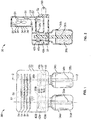
FIG. 1 is a diagrammatic representation of a first embodiment of a volatile material diffuser; -
FIG. 2 is a cross-sectional view taken generally along the lines 2-2 ofFIG. 1 ; -
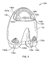
FIG. 3 is a front isometric view of a second embodiment of a volatile material diffuser; -
FIG. 4 is an exploded view of the diffuser ofFIG. 3 ; -
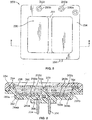
FIG. 5 is a front elevational view of a further embodiment of a volatile material diffuser; -
FIG. 6 is a cross-sectional view taken generally along the line 6-6 ofFIG. 5 ; and -
FIG. 7 is a flow chart illustrating programming of a fourth mode of operation that may be implemented by a programmable device for operation of various volatile material diffusers. - Other aspects and advantages of the present invention will become apparent upon consideration of the following detailed description and the attached drawings, in which like elements are assigned like reference numerals.
- Referring to
FIGS. 1 and 2 , avolatile material diffuser 30 generally includes ahousing 32. Twocontainers volatile materials wicks volatile materials containers housing 32. Thecontainers housing 32 by any means known in the art. - Referring again to
FIGS. 1 and 2 , thevolatile material diffuser 30 includes afirst chamber 37 havingheaters wicks volatile materials wicks top portions wicks wicks heaters channels first chamber 37. Thechannels wicks gap wicks cylindrical walls respective channels - An
optional fan 50 is disposed within asecond chamber 51 in arear portion 52 of thehousing 32 and slots orvents 54 are disposed opposite thefan 50 in afront wall 55 forming thechamber 51. Thefan 50 may be operated such that energy is continuously supplied thereto. Alternatively, energy may be supplied intermittently to thefan 50 to create intermittent flows of air. Optionally, separate fans may be utilized in combination with each of theheaters - Still referring to
FIGS. 1 and 2 , thediffuser 30 preferably, although not necessarily, has two electrical blades 60 (only one shown) extending from arear side 62 thereof for insertion into a common electrical socket. In this manner, thediffuser 30 is supplied direct current to operate a controller 64 (FIG. 2 ), theheaters fan 50. Optionally, thediffuser 30 may be battery-operated. - A further embodiment of a
volatile material diffuser 130 is depicted inFIGS. 3 and4 . Thediffuser 130 is similar to and works in manner similar to thediffuser 30 ofFIGS. 1 and 2 . Thediffuser 130 includes ahousing 132 for holding twocontainers volatile materials wicks FIG. 4 , thehousing 132 includes arear portion 138, acover portion 140, and amounting structure 142. Themounting structure 142 is attached to therear portion 138 and thecover portion 140 is mounted to therear portion 138 and themounting structure 142 such that themounting structure 142 is disposed between the rear andcover portions FIG. 4 , themounting structure 142 includes front andrear portions front portion 144a includes ahorizontal surface 146 havingfirst channels ring heaters first channels second channels ring heaters heaters first channels second channels heaters fan supporting structure 170 having afan 171 therein extends upwardly from therear portion 144b of the mountingstructure 142 above thesecond channels - As seen in
FIG. 4 , a controller in the form of a printed circuit board (PCB) 180 is secured within therear portion 144b of the mountingstructure 142 and includes all circuitry to control thediffuser 130. First and secondlight sources upper edge 184 of thePCB 180 and are disposed adjacentrear surfaces second channels light sources rear surfaces light sources respective heaters light sources heaters light sources heaters light sources light sources light sources diffuser 130. Thelight sources - Still referring to
FIG. 4 , anintensity selector switch 188 extends from thePCB 180 and includes anactuator arm 190 that extends through anaperture 192 in therear portion 138 of thehousing 132. Abutton 194 is disposed over theactuator arm 190 to change a position of theswitch 188. The position of theswitch 188 is sensed by thePCB 180 and an intensity level at which thevolatile materials switch 188. The intensity may be varied by changing a level of heat output by theheaters heaters heaters switch 188 may also be replaced by a dial, an LCD screen, one or more buttons, and/or any other know device that would allow a user to adjust a characteristic of a diffusion element or of a component of the diffuser. - The
light sources intensity level switch 188 of thediffuser 130 ofFIGS. 3 and4 may be utilized with any of the embodiments herein or any diffuser for dispensing one or more volatile materials. - As seen in
FIG. 4 , aplug assembly 210 is connected to therear portion 144b of the mountingstructure 142 and extends through anaperture 212 in therear portion 138 of thehousing 132.Electrical blades plug assembly 210 are inserted into an electrical socket to power thediffuser 130. - Referring to
FIG. 4 , thecontainers diffuser 130 by inserting portions of thewicks respective containers first channels wicks wicks first channels - The
diffusers 30 ofFIGS. 1 and 2 and 130 ofFIGS. 3 and4 are more fully disclosed inPorchia et al. U.S. Application Serial No. 11/427,714 , entitled "Volatile Material "Diffuser and Method of Preventing Undesirable Mixing of Volatile Materials," the disclosure of which is hereby incorporated by reference in its entirety. - Referring to
FIGS. 5 and 6 , afurther diffuser 250 generally includes abase portion 252 and a modulardecorative cover portion 254. Thebase portion 252 includes a plurality of heating pans 264a, 264b. A heater orheating element heating pan surface heating element heating pan heating element FIG. 6 ) disposed in thebase portion 252. - Referring to
FIGS. 5 , thebase portion 252 may include one or morelight sources corresponding heating pan light sources corresponding lighting orifices cover portion 254 is attached to thebase portion 252. Thelight sources light sources FIGS. 3 and4 . - Referring to
FIG. 5 , thebase portion 252 may also include an intensity selector switch 284, for example, in electrical communication with thecontroller 269 and disposed along a bottom edge as illustrated. The switch 284 may include a plurality of settings each corresponding to an intensity of heat that would be applied by theheating elements volatile material diffuser 250. - Referring to
FIG. 6 , thevolatile material holder 258 includes a plurality ofindependent reservoirs 260a, 260b. Each of the plurality ofindependent reservoirs 260a, 260b includes avolatile material flange 294. A non-porouspermeable membrane 296 is adhered to theflange 294 to cover each of the plurality ofreservoirs 260a, 260b and extends across thevolatile material holder 258. Thevolatile material holder 258 is similar to the volatile material holders described inU.S. Patent No. 7,441,360 , which is herein incorporated by reference in its entirety. Theimpermeable laminate 298 is removed from thevolatile material holder 258 before use. - A
surface heating element bottom surface 302 of eachindependent reservoir 260a, 260b, as shown inFIGS. 6 . Each of theindependent reservoirs 260a, 260b is heated by independent application of power via thecontroller 269 to each of theheating elements volatile material heating elements wall 300 therebetween. Thermal isolation between theheating elements volatile material independent reservoirs 260a, 260b. - Referring to
FIG. 6 , thebase portion 252 further includeselectrical prongs 304 that are in electrical communication with thecontroller 269 and extend substantially perpendicularly from arear surface 306 of thebase portion 252. Theelectrical prongs 304 are adapted to be inserted into a wall outlet to provide power to thediffuser 250. - The
diffuser 250 ofFIGS. 5 and 6 , and additional similar diffusers, are more fully disclosed inNeumann et al. U.S. Application Serial No. 12/319,606 , entitled "Fragrance Dispenser," the disclosure of which is hereby incorporated by reference in its entirety. - The volatile materials in any of the
diffusers - The
diffusers volatile material volatile materials controllers heaters - In a first mode of operation, when the
diffuser 30 is plugged into an electrical socket, a first of theheaters volatile materials first heater heaters volatile materials second heater first heater diffuser second heaters heaters next heater heaters other heater volatile materials - In the first, second, and third modes of operation, the first and second periods of time may be the same such that each
heater - The
controller controller -
FIG. 7 depicts programming for the fourth mode of operation that is implemented by the programmable device. In the fourth mode of operation, emission of volatile materials is alternated as described in detail with respect to any of the first, second, or third embodiments. The fourth mode of operation randomly varies the emission time periods and/or time periods during which the volatile materials are emitted. Optionally, if the second mode of operation is utilized, the third period of time (in which no diffusion element is activated), may be randomly varied or, if the third mode of operation is utilized, the fourth period of time (in which both diffusion elements are activated), may be randomly varied. - Referring to
FIG. 7 , operation begins at ablock 298 after thediffuser block 298 initializes the random number generator and ablock 300 initializes and starts the timer. Next, control passes to ablock 302 that operates the random number generator to generate a random number N1. Control then passes to ablock 304 that establishes a current emission time period (CETP) for the current volatile material in the sequence. The current emission time period is determined and set in part based on the number N1 selected by the random number generator as follows:
- For example, in one embodiment, the range of current emission time periods may be between about 45 minutes and about 120 minutes. In such case, a more specific equation used to determine the current emission time period may be:

- Using this equation with the base time period being 45 minutes and the time factor being 5 minutes, a minimum emission time period of 45 minutes is established and set if N1 is randomly selected to be 0 and a maximum emission time period of 120 minutes is established and set if N1 is randomly selected to be 15, with a number of potential random emission time periods therebetween.
- In a further exemplary embodiment, a range of current emission time periods may be between about 30 minutes and about 8 hours. In such case, a more specific equation used to determine the current emission time period may be:

- Using this equation with the base time period being 30 minutes and the time factor being 10 minutes, a minimum emission time period of 30 minutes is established and set if N1 is randomly selected to be 0 and a maximum emission time period of 480 minutes (or 8 hours) is established and set if N1 is randomly selected to be 45, with a number of potential random emission time periods therebetween.
- Although specific embodiments of the equation for determining the current emission time period are disclosed herein, a number of variations are possible. For example, the base time period is preferably programmed to be the minimum desired current emission time period, which is preferably between about 10 seconds and about 8 hours, more preferably between about 5 minutes and about 4 hours, and most preferably between about 45 minutes and about 2 hours. In addition, the time factor is preferably set to any number between about 10 seconds and about 8 hours, more preferably between about 1 minute and 60 minutes, and most preferably between about 5 minutes and about 30 minutes.
- Once the current emission time period is set at the
block 304 for a particular emission of a volatile material, control passes to ablock 306 wherein a diffusion element associated with the current volatile material is activated for the current emission time period. Ablock 308 then determines whether the current emission time period has elapsed and control remains with theblock 308 until the current emission time period has elapsed. Once theblock 308 determines that the current emission time period has elapsed, control passes to ablock 310 that determines which diffusion element is next in the sequence. After theblock 310, control returns to theblock 302 where the random number generator generates a number N1 and operation continues to cycle through the loop ofFIG. 7 including theblocks diffuser - Diffusion element(s) as referred to in
FIG. 7 may be any type of element that promotes diffusion of a volatile material. Examples of diffusion elements include, but are not limited to, aerosol actuators, piezoelectric elements, heaters, fans, nebulizers, and the like. To that effect, any of the modes of operation disclosed herein may be utilized with any type of diffusion element and/or combinations of diffusion elements (e.g. a device that utilizes multiple heaters and a single fan, a device that utilizes a heater to diffuse a first volatile material and a fan to diffuse a second material, etc.). - The modes of operation disclosed herein may be utilized for any diffuser that emits two or more volatile materials. In particular, any number of volatile materials may be emitted. In addition, such modes may be utilized to diffuse volatile materials in any form, such as aerosols, gels, liquids, solids, and the like.
- The present invention provides volatile material diffusers for emitting at least one volatile material therefrom, wherein, if multiple volatile materials are emitted, the volatile materials are emitted in an alternating sequence. The volatile materials are disclosed as being vaporized by heaters, fans, or any other known diffusion element. Various modes of operation are disclosed for alternating the volatile materials in order to limit or prevent habituation. One or more LEDs may be incorporated into is diffuser to indicate which volatile material(s) is being emitted.
Claims (8)
- A method of emitting two or more volatile materials from a diffuser (13, 130, 250) the method comprising the steps of:initializing a random number generator;emitting a first volatile material (35a, 135a, 262a) using a first diffusion element (38a, 138a, 266a) for a first randomly determined period of time; andemitting a second volatile material (35b, 135b, 262b) using a second diffusion element (38b, 138b, 266b) for a second randomly determined period of time;wherein:the first randomly determined period of time is equal to a base time period plus a first incremental time period, wherein the first incremental time period is determined by:a) operating the random number generator to generate a first random number; andb) multiplying the first random number by a time factor to produce the first incremental time period; andthe second randomly determined period of time is equal to the base time period plus a second incremental time period, wherein the second incremental time period is determined by:a) operating the random number generator again to generate a second random number; andb) multiplying the second random number by the time factor to produce the second incremental time period.
- The method of claim 1, wherein the first and second diffusion elements (38a, 38b, 138a, 138b, 266a, 266b) are heaters.
- The method of claim 1, wherein the first and second diffusion elements are fans.
- The method of claim 1, wherein the first and second volatile materials (35a, 35b, 135a, 135b, 262a, 262b) are emitted by activating first and second heaters (38a, 38b, 138a, 138b, 266a, 266b), respectively, and wherein the method further includes the step of deactivating the first heater (38a, 138a, 266a) before activation of the second heater (38b, 138b, 266b) to create a period of time in which no heater is activated.
- The method of claim 4, wherein the period of time in which no heater is activated is determined randomly.
- The method of claim 1, wherein the base time period is set to between about 10 seconds and about 8 hours and the time factor is set to be between about 10 seconds and about 8 hours.
- The method of claim 6, wherein the base time period is set to be about 45 minutes, the time factor is set to be about 5 minutes, and N1 is randomly selected between 0 and 15 such that each current emission time period is between about 45 minutes and about 120 minutes.
- The method of claim 1, 6, or 7 wherein a fan is used to dispense at least one of the first and second volatile materials.
Applications Claiming Priority (2)
| Application Number | Priority Date | Filing Date | Title |
|---|---|---|---|
| US24428509P | 2009-09-21 | 2009-09-21 | |
| PCT/US2010/002558 WO2011034613A1 (en) | 2009-09-21 | 2010-09-20 | Methods of emitting a volatile material from a diffuser |
Publications (3)
| Publication Number | Publication Date |
|---|---|
| EP2480259A1 EP2480259A1 (en) | 2012-08-01 |
| EP2480259B1 EP2480259B1 (en) | 2014-11-19 |
| EP2480259B2 true EP2480259B2 (en) | 2020-06-03 |
Family
ID=43217007
Family Applications (1)
| Application Number | Title | Priority Date | Filing Date |
|---|---|---|---|
| EP10766370.0A Active EP2480259B2 (en) | 2009-09-21 | 2010-09-20 | Methods of emitting a volatile material from a diffuser |
Country Status (6)
| Country | Link |
|---|---|
| US (1) | US9669125B2 (en) |
| EP (1) | EP2480259B2 (en) |
| CN (1) | CN102740899B (en) |
| ES (1) | ES2527300T5 (en) |
| MX (1) | MX2012003412A (en) |
| WO (1) | WO2011034613A1 (en) |
Families Citing this family (16)
| Publication number | Priority date | Publication date | Assignee | Title |
|---|---|---|---|---|
| CN102986639B (en) * | 2012-10-12 | 2015-11-18 | 苏州征之魂专利技术服务有限公司 | A kind of electric heating is except mosquito method and structure thereof |
| EP3370782A4 (en) | 2015-11-02 | 2019-07-24 | Pura Scents, Inc. | DISTRIBUTION OF FRAGRANCE |
| CN106075524B (en) * | 2016-01-21 | 2019-01-18 | 朱其厚 | A kind of Combined-type portable scent device |
| US11090404B2 (en) * | 2016-05-19 | 2021-08-17 | The Procter & Gamble Company | Systems for dispensing fluid materials |
| ES2674975B1 (en) * | 2017-01-05 | 2019-04-09 | Zobele Espana Sa | Replacement for evaporating devices for volatile substances |
| CN110785093B (en) * | 2017-07-07 | 2023-04-07 | 菲利普莫里斯生产公司 | Aerosol-generating system with four contacts |
| CN107551710A (en) * | 2017-10-17 | 2018-01-09 | 北京林业大学 | A kind of gas thermic streaming energy inhales haze device |
| CN107961393B (en) * | 2017-12-30 | 2023-11-17 | 广州驰扬香氛科技有限公司 | Fragrance equipment |
| CN111511410B (en) | 2018-01-18 | 2022-10-11 | 宝洁公司 | Method of delivering volatile compositions into the air |
| FR3091998A1 (en) * | 2019-01-26 | 2020-07-31 | Yacine Ouerdani | Device for infusing / flavoring / flavoring / maturing all products |
| CN209965060U (en) * | 2019-03-28 | 2020-01-21 | 深圳市乐氛实业有限公司 | Mosquito dispeller with good mosquito killing effect |
| US20220354105A1 (en) * | 2021-05-07 | 2022-11-10 | Lamplight Farms Incorporated | Insect repellent liquid dispenser |
| CN113028558A (en) * | 2021-05-11 | 2021-06-25 | 蔡建锋 | Novel air purifier |
| US12089585B2 (en) * | 2021-07-05 | 2024-09-17 | Flextail Technology Co., Ltd | Double-sided mosquito repeller |
| US20230226242A1 (en) * | 2022-01-19 | 2023-07-20 | Beautyavenues Llc | Plug-In Fragrance Diffuser, And Systems And Methods For Using Same |
| CN117121902A (en) * | 2023-06-20 | 2023-11-28 | 李文杰 | Compound multiple-effect mosquito prevention and control device |
Citations (1)
| Publication number | Priority date | Publication date | Assignee | Title |
|---|---|---|---|---|
| JPH05173648A (en) † | 1992-04-17 | 1993-07-13 | Toyota Central Res & Dev Lab Inc | Fluctuation drive for fragrance |
Family Cites Families (60)
| Publication number | Priority date | Publication date | Assignee | Title |
|---|---|---|---|---|
| GB1120970A (en) | 1964-12-22 | 1968-07-24 | Sadakichi Sugimura | Automatic perfume atomizer |
| US3948445A (en) | 1973-06-26 | 1976-04-06 | Andeweg Frits J | Material vapor generator with heat accelerated vapor release |
| ES262127Y (en) | 1981-12-17 | 1982-12-16 | PERFECTED DOMESTIC ELECTRICAL DEVICE, SUBLIMATOR OF PERFUMING PILLS AND-OR INSECTICIDES. | |
| US5029729A (en) | 1983-12-09 | 1991-07-09 | Milliken Denmark A/S | Method of dispensing vapor to the air in a room and an apparatus for carrying out the method |
| US4603030A (en) | 1984-09-20 | 1986-07-29 | Mccarthy Robert E | Scent-Emitting Systems |
| FR2623600B1 (en) | 1987-11-19 | 1990-04-06 | Armines | STEAM GENERATOR |
| US4849606A (en) | 1987-12-23 | 1989-07-18 | S. C. Johnson & Son, Inc. | Tamper-resistant container utilizing a flexible seal |
| US5111477A (en) | 1990-05-07 | 1992-05-05 | Technical Concepts, L.P. | Fragrance diffuser |
| US5175791A (en) | 1990-05-07 | 1992-12-29 | Technical Concepts, L.P. | Fragrance diffuser having stepped power levels |
| US5297988A (en) * | 1990-11-02 | 1994-03-29 | Nippondenso Co., Ltd. | Fragrance supplying apparatus for vehicle |
| US5591395A (en) | 1995-08-03 | 1997-01-07 | S. C. Johnson & Son, Inc. | Method of disinfecting air |
| US5591409A (en) | 1995-08-15 | 1997-01-07 | Watkins; Carl J. | Providing aromas |
| US5647053A (en) | 1995-10-11 | 1997-07-08 | S. C. Johnson & Son, Inc. | Vapor dipensing device |
| US5937140A (en) | 1996-09-23 | 1999-08-10 | S. C. Johnson & Son, Inc. | Thermal-fuse plug-through, plug-in diffuser |
| US6923383B1 (en) | 2000-08-24 | 2005-08-02 | Microlin, L.C. | Controlled release of substances |
| US6390453B1 (en) | 1997-10-22 | 2002-05-21 | Microfab Technologies, Inc. | Method and apparatus for delivery of fragrances and vapors to the nose |
| US6204623B1 (en) | 1998-12-17 | 2001-03-20 | The Holmes Group, Inc. | Heater, humidifier or fan including a circuit for controlling the output thereof |
| FR2795348B1 (en) * | 1999-06-22 | 2001-09-14 | Osmooze Sa | PROGRAMMABLE DEVICE FOR SCATTERING ODOR PICS |
| GB9916755D0 (en) | 1999-07-17 | 1999-09-15 | Reckitt & Colmann Prod Ltd | Improvements in or relating to organic compositions |
| US6792199B2 (en) | 2000-02-25 | 2004-09-14 | The Dial Corporation | Variable temperature vaporizer |
| CA2337738C (en) | 2000-02-25 | 2008-05-13 | The Dial Corporation | Variable temperature vaporizer |
| US6478440B1 (en) | 2000-03-10 | 2002-11-12 | S.C. Johnson & Son, Inc. | Night light air freshener |
| JP5327416B2 (en) | 2000-05-26 | 2013-10-30 | 株式会社シームス | Odor generating method and odor generating device |
| US20040028551A1 (en) * | 2000-07-27 | 2004-02-12 | Kvietok Frank Andrej | Methods for emitting volatile compositions |
| US20040033171A1 (en) * | 2000-07-27 | 2004-02-19 | The Procter & Gamble Company | Systems and devices for emitting volatile compositions |
| US6581915B2 (en) | 2000-07-27 | 2003-06-24 | The Procter & Gamble Company | Dispensing device for dispensing scents |
| US20040265164A1 (en) * | 2000-07-27 | 2004-12-30 | The Procter & Gamble Company | Methods, devices, compositions, and systems for improved scent delivery |
| US6931202B2 (en) | 2000-07-28 | 2005-08-16 | S.C. Johnson & Son, Inc. | Electrical evaporator with adjustable evaporation intensity |
| US20040007787A1 (en) * | 2000-12-05 | 2004-01-15 | The Procter & Gamble Company | Articles, systems, and methods for dispensing volatile materials |
| GB2369816B (en) | 2000-12-06 | 2004-12-22 | Dudley Ind Ltd | Dispensing device |
| EP1249163A1 (en) | 2001-04-09 | 2002-10-16 | Zelnova, S.A. | Thermal vaporizer for a liquid formulation comprising a volatile active |
| US6862403B2 (en) | 2001-08-07 | 2005-03-01 | S.C. Johnson & Son, Inc. | Rotatable plug assembly including an extra outlet |
| ATE324914T1 (en) | 2001-08-07 | 2006-06-15 | Johnson & Son Inc S C | ELECTRIC POLYFUNCTIONAL WALL SOCKET VAPORIZER |
| GB0123851D0 (en) | 2001-10-04 | 2001-11-28 | Pankhurst Design & Development | Dispersing fragrances |
| US6857580B2 (en) | 2001-12-03 | 2005-02-22 | S.C. Johnson & Son, Inc. | Plug-in type liquid atomizer |
| US7036800B2 (en) | 2002-04-08 | 2006-05-02 | Ellis Earle R | Automatically controlling the interaction of a medium with an external environment |
| EP1495771A1 (en) | 2002-04-12 | 2005-01-12 | DBK Espana, S.A. | Active substance evaporator |
| US20040033067A1 (en) | 2002-08-16 | 2004-02-19 | He Mengtao Pete | Methods and apparatus for a controllable vapor-dispensing device |
| US7249719B2 (en) | 2002-08-30 | 2007-07-31 | The Dial Corporation | Method and apparatus for a multiple source vapor-dispensing device |
| EP1407790A1 (en) | 2002-10-10 | 2004-04-14 | Spy Marketing Sdn. Bhd. | Improved olfactory stimulating material dispensing apparatus |
| US7469844B2 (en) * | 2002-11-08 | 2008-12-30 | S.C. Johnson & Son, Inc. | Diffusion device and method of diffusing |
| DE10334591B4 (en) | 2003-07-28 | 2006-03-30 | International Flavors & Fragrances Inc. | Method for distributing liquid fragrances and apparatus for carrying out the method |
| US20080014125A1 (en) | 2003-08-28 | 2008-01-17 | The Dial Corporation | Method and apparatus for a multiple source vapor-dispensing device |
| US20070166186A1 (en) | 2004-02-11 | 2007-07-19 | Stec Michael J | Descenting apparatus and method |
| US6996335B2 (en) | 2004-02-12 | 2006-02-07 | S.C. Johnson & Son, Inc. | Electrical evaporator with ratcheting wick adjuster |
| WO2005092400A1 (en) | 2004-03-26 | 2005-10-06 | C.T.R. Consultoria Tecnica E Representacoes, Lda. | Device for the evaporation of volatile substances, in particular of aromatics and/or insecticides |
| US7484716B2 (en) | 2004-04-14 | 2009-02-03 | University Of Southern California | Scent delivery device and method of simulating scent in a virtual environment |
| US7441360B2 (en) | 2004-06-30 | 2008-10-28 | S.C. Johnson & Son, Inc. | Air freshener with picture frame |
| WO2006084921A1 (en) | 2005-02-03 | 2006-08-17 | Zobele España, S.A. | Diffuser for volatile substances with multiple fragrances |
| US7622073B2 (en) | 2005-04-12 | 2009-11-24 | S.C. Johnson & Son, Inc. | Apparatus for and method of dispensing active materials |
| KR20080009685A (en) * | 2005-04-12 | 2008-01-29 | 에스.씨. 존슨 앤드 선, 인코포레이티드 | Diffusion Mechanism and Diffusion Method |
| WO2007064189A1 (en) | 2005-12-01 | 2007-06-07 | Sara Lee/De N.V. | Fragrance delivery system |
| WO2007079046A1 (en) | 2005-12-30 | 2007-07-12 | The Dial Corporation | Method to overcome air freshener odor habituation |
| US20070160492A1 (en) | 2006-01-11 | 2007-07-12 | Donald Spector | Electronic room freshener and method for releasing fragrances |
| US7493028B2 (en) | 2006-04-04 | 2009-02-17 | Group Dekko, Inc. | Multiple bottle evaporative diffuser |
| CN101557834A (en) | 2006-10-20 | 2009-10-14 | 沙彼高控股有限公司 | Electric evaporator device of volatile substances with adjustable evaporation intensity |
| GB0622743D0 (en) | 2006-11-15 | 2006-12-27 | Reckitt Benckiser Uk Ltd | Device |
| GB0710572D0 (en) | 2007-06-02 | 2007-07-11 | Reckitt Benckiser Uk Ltd | Spraying device |
| US8320751B2 (en) * | 2007-12-20 | 2012-11-27 | S.C. Johnson & Son, Inc. | Volatile material diffuser and method of preventing undesirable mixing of volatile materials |
| JP5173648B2 (en) | 2008-07-29 | 2013-04-03 | 京セラ株式会社 | Content output device |
-
2010
- 2010-09-20 MX MX2012003412A patent/MX2012003412A/en active IP Right Grant
- 2010-09-20 EP EP10766370.0A patent/EP2480259B2/en active Active
- 2010-09-20 WO PCT/US2010/002558 patent/WO2011034613A1/en not_active Ceased
- 2010-09-20 US US12/886,048 patent/US9669125B2/en active Active
- 2010-09-20 ES ES10766370T patent/ES2527300T5/en active Active
- 2010-09-20 CN CN201080052656.8A patent/CN102740899B/en active Active
Patent Citations (1)
| Publication number | Priority date | Publication date | Assignee | Title |
|---|---|---|---|---|
| JPH05173648A (en) † | 1992-04-17 | 1993-07-13 | Toyota Central Res & Dev Lab Inc | Fluctuation drive for fragrance |
Also Published As
| Publication number | Publication date |
|---|---|
| MX2012003412A (en) | 2012-04-30 |
| EP2480259A1 (en) | 2012-08-01 |
| US20110068190A1 (en) | 2011-03-24 |
| WO2011034613A9 (en) | 2012-06-07 |
| WO2011034613A1 (en) | 2011-03-24 |
| CN102740899B (en) | 2015-01-21 |
| ES2527300T5 (en) | 2021-03-03 |
| CN102740899A (en) | 2012-10-17 |
| US9669125B2 (en) | 2017-06-06 |
| EP2480259B1 (en) | 2014-11-19 |
| ES2527300T3 (en) | 2015-01-22 |
Similar Documents
| Publication | Publication Date | Title |
|---|---|---|
| EP2480259B1 (en) | Methods of emitting a volatile material from a diffuser | |
| EP1613360B1 (en) | System for emitting volatile compositions | |
| CA2522564C (en) | Method for emitting volatile compositions | |
| EP2240209B1 (en) | Volatile material diffuser and method of preventing undesirable mixing of volatile materials | |
| JP5553845B2 (en) | Air freshener supplier | |
| US8061628B1 (en) | Systems and devices for emitting volatile compositions | |
| US20050285538A1 (en) | Active material emitting device | |
| US8197762B2 (en) | Method of dispensing a volatile material | |
| ES2733597T3 (en) | Method of dispensing a volatile material | |
| EP2160204A1 (en) | Active material emitting device and method of dispensing an active material |
Legal Events
| Date | Code | Title | Description |
|---|---|---|---|
| PUAI | Public reference made under article 153(3) epc to a published international application that has entered the european phase |
Free format text: ORIGINAL CODE: 0009012 |
|
| 17P | Request for examination filed |
Effective date: 20120404 |
|
| AK | Designated contracting states |
Kind code of ref document: A1 Designated state(s): AL AT BE BG CH CY CZ DE DK EE ES FI FR GB GR HR HU IE IS IT LI LT LU LV MC MK MT NL NO PL PT RO SE SI SK SM TR |
|
| DAX | Request for extension of the european patent (deleted) | ||
| 17Q | First examination report despatched |
Effective date: 20131206 |
|
| GRAP | Despatch of communication of intention to grant a patent |
Free format text: ORIGINAL CODE: EPIDOSNIGR1 |
|
| INTG | Intention to grant announced |
Effective date: 20140807 |
|
| GRAS | Grant fee paid |
Free format text: ORIGINAL CODE: EPIDOSNIGR3 |
|
| GRAA | (expected) grant |
Free format text: ORIGINAL CODE: 0009210 |
|
| AK | Designated contracting states |
Kind code of ref document: B1 Designated state(s): AL AT BE BG CH CY CZ DE DK EE ES FI FR GB GR HR HU IE IS IT LI LT LU LV MC MK MT NL NO PL PT RO SE SI SK SM TR |
|
| REG | Reference to a national code |
Ref country code: GB Ref legal event code: FG4D |
|
| REG | Reference to a national code |
Ref country code: CH Ref legal event code: EP |
|
| REG | Reference to a national code |
Ref country code: AT Ref legal event code: REF Ref document number: 696614 Country of ref document: AT Kind code of ref document: T Effective date: 20141215 |
|
| REG | Reference to a national code |
Ref country code: IE Ref legal event code: FG4D |
|
| REG | Reference to a national code |
Ref country code: DE Ref legal event code: R096 Ref document number: 602010020414 Country of ref document: DE Effective date: 20141231 |
|
| REG | Reference to a national code |
Ref country code: ES Ref legal event code: FG2A Ref document number: 2527300 Country of ref document: ES Kind code of ref document: T3 Effective date: 20150122 |
|
| REG | Reference to a national code |
Ref country code: NL Ref legal event code: VDEP Effective date: 20141119 |
|
| REG | Reference to a national code |
Ref country code: AT Ref legal event code: MK05 Ref document number: 696614 Country of ref document: AT Kind code of ref document: T Effective date: 20141119 |
|
| REG | Reference to a national code |
Ref country code: LT Ref legal event code: MG4D |
|
| PG25 | Lapsed in a contracting state [announced via postgrant information from national office to epo] |
Ref country code: NO Free format text: LAPSE BECAUSE OF FAILURE TO SUBMIT A TRANSLATION OF THE DESCRIPTION OR TO PAY THE FEE WITHIN THE PRESCRIBED TIME-LIMIT Effective date: 20150219 Ref country code: IS Free format text: LAPSE BECAUSE OF FAILURE TO SUBMIT A TRANSLATION OF THE DESCRIPTION OR TO PAY THE FEE WITHIN THE PRESCRIBED TIME-LIMIT Effective date: 20150319 Ref country code: LT Free format text: LAPSE BECAUSE OF FAILURE TO SUBMIT A TRANSLATION OF THE DESCRIPTION OR TO PAY THE FEE WITHIN THE PRESCRIBED TIME-LIMIT Effective date: 20141119 Ref country code: NL Free format text: LAPSE BECAUSE OF FAILURE TO SUBMIT A TRANSLATION OF THE DESCRIPTION OR TO PAY THE FEE WITHIN THE PRESCRIBED TIME-LIMIT Effective date: 20141119 Ref country code: PT Free format text: LAPSE BECAUSE OF FAILURE TO SUBMIT A TRANSLATION OF THE DESCRIPTION OR TO PAY THE FEE WITHIN THE PRESCRIBED TIME-LIMIT Effective date: 20150319 Ref country code: FI Free format text: LAPSE BECAUSE OF FAILURE TO SUBMIT A TRANSLATION OF THE DESCRIPTION OR TO PAY THE FEE WITHIN THE PRESCRIBED TIME-LIMIT Effective date: 20141119 |
|
| PG25 | Lapsed in a contracting state [announced via postgrant information from national office to epo] |
Ref country code: AT Free format text: LAPSE BECAUSE OF FAILURE TO SUBMIT A TRANSLATION OF THE DESCRIPTION OR TO PAY THE FEE WITHIN THE PRESCRIBED TIME-LIMIT Effective date: 20141119 Ref country code: HR Free format text: LAPSE BECAUSE OF FAILURE TO SUBMIT A TRANSLATION OF THE DESCRIPTION OR TO PAY THE FEE WITHIN THE PRESCRIBED TIME-LIMIT Effective date: 20141119 Ref country code: GR Free format text: LAPSE BECAUSE OF FAILURE TO SUBMIT A TRANSLATION OF THE DESCRIPTION OR TO PAY THE FEE WITHIN THE PRESCRIBED TIME-LIMIT Effective date: 20150220 Ref country code: PL Free format text: LAPSE BECAUSE OF FAILURE TO SUBMIT A TRANSLATION OF THE DESCRIPTION OR TO PAY THE FEE WITHIN THE PRESCRIBED TIME-LIMIT Effective date: 20141119 Ref country code: CY Free format text: LAPSE BECAUSE OF FAILURE TO SUBMIT A TRANSLATION OF THE DESCRIPTION OR TO PAY THE FEE WITHIN THE PRESCRIBED TIME-LIMIT Effective date: 20141119 Ref country code: SE Free format text: LAPSE BECAUSE OF FAILURE TO SUBMIT A TRANSLATION OF THE DESCRIPTION OR TO PAY THE FEE WITHIN THE PRESCRIBED TIME-LIMIT Effective date: 20141119 Ref country code: LV Free format text: LAPSE BECAUSE OF FAILURE TO SUBMIT A TRANSLATION OF THE DESCRIPTION OR TO PAY THE FEE WITHIN THE PRESCRIBED TIME-LIMIT Effective date: 20141119 |
|
| PG25 | Lapsed in a contracting state [announced via postgrant information from national office to epo] |
Ref country code: SK Free format text: LAPSE BECAUSE OF FAILURE TO SUBMIT A TRANSLATION OF THE DESCRIPTION OR TO PAY THE FEE WITHIN THE PRESCRIBED TIME-LIMIT Effective date: 20141119 Ref country code: CZ Free format text: LAPSE BECAUSE OF FAILURE TO SUBMIT A TRANSLATION OF THE DESCRIPTION OR TO PAY THE FEE WITHIN THE PRESCRIBED TIME-LIMIT Effective date: 20141119 Ref country code: DK Free format text: LAPSE BECAUSE OF FAILURE TO SUBMIT A TRANSLATION OF THE DESCRIPTION OR TO PAY THE FEE WITHIN THE PRESCRIBED TIME-LIMIT Effective date: 20141119 Ref country code: RO Free format text: LAPSE BECAUSE OF FAILURE TO SUBMIT A TRANSLATION OF THE DESCRIPTION OR TO PAY THE FEE WITHIN THE PRESCRIBED TIME-LIMIT Effective date: 20141119 Ref country code: EE Free format text: LAPSE BECAUSE OF FAILURE TO SUBMIT A TRANSLATION OF THE DESCRIPTION OR TO PAY THE FEE WITHIN THE PRESCRIBED TIME-LIMIT Effective date: 20141119 |
|
| REG | Reference to a national code |
Ref country code: DE Ref legal event code: R026 Ref document number: 602010020414 Country of ref document: DE |
|
| PLBI | Opposition filed |
Free format text: ORIGINAL CODE: 0009260 |
|
| PLAX | Notice of opposition and request to file observation + time limit sent |
Free format text: ORIGINAL CODE: EPIDOSNOBS2 |
|
| 26 | Opposition filed |
Opponent name: THE PROCTER & GAMBLE COMPANY Effective date: 20150819 |
|
| PLBB | Reply of patent proprietor to notice(s) of opposition received |
Free format text: ORIGINAL CODE: EPIDOSNOBS3 |
|
| PG25 | Lapsed in a contracting state [announced via postgrant information from national office to epo] |
Ref country code: SI Free format text: LAPSE BECAUSE OF FAILURE TO SUBMIT A TRANSLATION OF THE DESCRIPTION OR TO PAY THE FEE WITHIN THE PRESCRIBED TIME-LIMIT Effective date: 20141119 |
|
| REG | Reference to a national code |
Ref country code: DE Ref legal event code: R119 Ref document number: 602010020414 Country of ref document: DE |
|
| PG25 | Lapsed in a contracting state [announced via postgrant information from national office to epo] |
Ref country code: LU Free format text: LAPSE BECAUSE OF FAILURE TO SUBMIT A TRANSLATION OF THE DESCRIPTION OR TO PAY THE FEE WITHIN THE PRESCRIBED TIME-LIMIT Effective date: 20150920 Ref country code: MC Free format text: LAPSE BECAUSE OF FAILURE TO SUBMIT A TRANSLATION OF THE DESCRIPTION OR TO PAY THE FEE WITHIN THE PRESCRIBED TIME-LIMIT Effective date: 20141119 |
|
| REG | Reference to a national code |
Ref country code: CH Ref legal event code: PL |
|
| REG | Reference to a national code |
Ref country code: IE Ref legal event code: MM4A |
|
| REG | Reference to a national code |
Ref country code: FR Ref legal event code: ST Effective date: 20160531 |
|
| PG25 | Lapsed in a contracting state [announced via postgrant information from national office to epo] |
Ref country code: CH Free format text: LAPSE BECAUSE OF NON-PAYMENT OF DUE FEES Effective date: 20150930 Ref country code: IE Free format text: LAPSE BECAUSE OF NON-PAYMENT OF DUE FEES Effective date: 20150920 Ref country code: LI Free format text: LAPSE BECAUSE OF NON-PAYMENT OF DUE FEES Effective date: 20150930 Ref country code: DE Free format text: LAPSE BECAUSE OF NON-PAYMENT OF DUE FEES Effective date: 20160401 |
|
| PG25 | Lapsed in a contracting state [announced via postgrant information from national office to epo] |
Ref country code: FR Free format text: LAPSE BECAUSE OF NON-PAYMENT OF DUE FEES Effective date: 20150930 |
|
| PG25 | Lapsed in a contracting state [announced via postgrant information from national office to epo] |
Ref country code: MT Free format text: LAPSE BECAUSE OF FAILURE TO SUBMIT A TRANSLATION OF THE DESCRIPTION OR TO PAY THE FEE WITHIN THE PRESCRIBED TIME-LIMIT Effective date: 20141119 |
|
| PG25 | Lapsed in a contracting state [announced via postgrant information from national office to epo] |
Ref country code: SM Free format text: LAPSE BECAUSE OF FAILURE TO SUBMIT A TRANSLATION OF THE DESCRIPTION OR TO PAY THE FEE WITHIN THE PRESCRIBED TIME-LIMIT Effective date: 20141119 Ref country code: BG Free format text: LAPSE BECAUSE OF FAILURE TO SUBMIT A TRANSLATION OF THE DESCRIPTION OR TO PAY THE FEE WITHIN THE PRESCRIBED TIME-LIMIT Effective date: 20141119 Ref country code: HU Free format text: LAPSE BECAUSE OF FAILURE TO SUBMIT A TRANSLATION OF THE DESCRIPTION OR TO PAY THE FEE WITHIN THE PRESCRIBED TIME-LIMIT; INVALID AB INITIO Effective date: 20100920 |
|
| APBM | Appeal reference recorded |
Free format text: ORIGINAL CODE: EPIDOSNREFNO |
|
| APBP | Date of receipt of notice of appeal recorded |
Free format text: ORIGINAL CODE: EPIDOSNNOA2O |
|
| APAH | Appeal reference modified |
Free format text: ORIGINAL CODE: EPIDOSCREFNO |
|
| PG25 | Lapsed in a contracting state [announced via postgrant information from national office to epo] |
Ref country code: TR Free format text: LAPSE BECAUSE OF FAILURE TO SUBMIT A TRANSLATION OF THE DESCRIPTION OR TO PAY THE FEE WITHIN THE PRESCRIBED TIME-LIMIT Effective date: 20141119 |
|
| PG25 | Lapsed in a contracting state [announced via postgrant information from national office to epo] |
Ref country code: BE Free format text: LAPSE BECAUSE OF FAILURE TO SUBMIT A TRANSLATION OF THE DESCRIPTION OR TO PAY THE FEE WITHIN THE PRESCRIBED TIME-LIMIT Effective date: 20141119 |
|
| APBQ | Date of receipt of statement of grounds of appeal recorded |
Free format text: ORIGINAL CODE: EPIDOSNNOA3O |
|
| PG25 | Lapsed in a contracting state [announced via postgrant information from national office to epo] |
Ref country code: MK Free format text: LAPSE BECAUSE OF FAILURE TO SUBMIT A TRANSLATION OF THE DESCRIPTION OR TO PAY THE FEE WITHIN THE PRESCRIBED TIME-LIMIT Effective date: 20141119 |
|
| PG25 | Lapsed in a contracting state [announced via postgrant information from national office to epo] |
Ref country code: AL Free format text: LAPSE BECAUSE OF FAILURE TO SUBMIT A TRANSLATION OF THE DESCRIPTION OR TO PAY THE FEE WITHIN THE PRESCRIBED TIME-LIMIT Effective date: 20141119 |
|
| APBU | Appeal procedure closed |
Free format text: ORIGINAL CODE: EPIDOSNNOA9O |
|
| PUAH | Patent maintained in amended form |
Free format text: ORIGINAL CODE: 0009272 |
|
| STAA | Information on the status of an ep patent application or granted ep patent |
Free format text: STATUS: PATENT MAINTAINED AS AMENDED |
|
| 27A | Patent maintained in amended form |
Effective date: 20200603 |
|
| AK | Designated contracting states |
Kind code of ref document: B2 Designated state(s): AL AT BE BG CH CY CZ DE DK EE ES FI FR GB GR HR HU IE IS IT LI LT LU LV MC MK MT NL NO PL PT RO SE SI SK SM TR |
|
| REG | Reference to a national code |
Ref country code: DE Ref legal event code: R102 Ref document number: 602010020414 Country of ref document: DE |
|
| REG | Reference to a national code |
Ref country code: ES Ref legal event code: DC2A Ref document number: 2527300 Country of ref document: ES Kind code of ref document: T5 Effective date: 20210303 |
|
| P01 | Opt-out of the competence of the unified patent court (upc) registered |
Effective date: 20230528 |
|
| PGFP | Annual fee paid to national office [announced via postgrant information from national office to epo] |
Ref country code: IT Payment date: 20250820 Year of fee payment: 16 |
|
| PGFP | Annual fee paid to national office [announced via postgrant information from national office to epo] |
Ref country code: GB Payment date: 20250822 Year of fee payment: 16 |
|
| PGFP | Annual fee paid to national office [announced via postgrant information from national office to epo] |
Ref country code: ES Payment date: 20251001 Year of fee payment: 16 |