EP2479648A1 - Mouse with wire arrangement structure - Google Patents
Mouse with wire arrangement structure Download PDFInfo
- Publication number
- EP2479648A1 EP2479648A1 EP11151379A EP11151379A EP2479648A1 EP 2479648 A1 EP2479648 A1 EP 2479648A1 EP 11151379 A EP11151379 A EP 11151379A EP 11151379 A EP11151379 A EP 11151379A EP 2479648 A1 EP2479648 A1 EP 2479648A1
- Authority
- EP
- European Patent Office
- Prior art keywords
- base
- wire
- connection
- mouse
- housing
- Prior art date
- Legal status (The legal status is an assumption and is not a legal conclusion. Google has not performed a legal analysis and makes no representation as to the accuracy of the status listed.)
- Withdrawn
Links
Images


Classifications
-
- G—PHYSICS
- G06—COMPUTING OR CALCULATING; COUNTING
- G06F—ELECTRIC DIGITAL DATA PROCESSING
- G06F3/00—Input arrangements for transferring data to be processed into a form capable of being handled by the computer; Output arrangements for transferring data from processing unit to output unit, e.g. interface arrangements
- G06F3/01—Input arrangements or combined input and output arrangements for interaction between user and computer
- G06F3/03—Arrangements for converting the position or the displacement of a member into a coded form
- G06F3/033—Pointing devices displaced or positioned by the user, e.g. mice, trackballs, pens or joysticks; Accessories therefor
- G06F3/0354—Pointing devices displaced or positioned by the user, e.g. mice, trackballs, pens or joysticks; Accessories therefor with detection of two-dimensional [2D] relative movements between the device, or an operating part thereof, and a plane or surface, e.g. 2D mice, trackballs, pens or pucks
- G06F3/03543—Mice or pucks
Definitions
- the present invention relates to a wired mouse, and in particular relates to a mouse with a wire arrangement structure.
- a conventional wired mouse comprises a mouse body and a wire.
- the wire connects the mouse body to an electronic device (for example, computer) via a joint.
- an electronic device for example, computer
- a mouse with a wire arrangement structure includes a housing, a base, a connection unit and a wire.
- the housing includes an opening and an opening edge.
- the base corresponds to the housing, wherein the base is moved between a first position and a second position, and when the base is in the first position, the base abuts the opening edge to cover the opening, and when the base is in the second position, the base is separated from the opening edge.
- the connection unit is connected to the housing and the base, allowing the base to move relative to the housing.
- the wire includes a joint, wherein when the wire is in a receiving state, the wire is wound up around the connection unit.
- the wire and the joint are received in a chamber formed by the housing and the base, and the joint (free end) of the wire is prevented from being loosened, and the mouse is easily carried.
- the wire partially is wound up around the connection pillar to decrease the length of the wire exposed on the outside of the mouse.
- Fig. 1A shows a mouse with a wire arrangement structure of a first embodiment of the invention, wherein a base thereof is in a first position;
- Fig. 1B shows the mouse with a wire arrangement structure of the first embodiment of the invention, wherein the base thereof is in a second position;
- Fig. 1C shows a wire of the mouse of the first embodiment of the invention received in a housing
- Fig. 2 shows a detailed structure of a first arm, a restriction block and a first restriction slot of the mouse of the first embodiment of the invention
- Fig. 3A shows a mouse with a wire arrangement structure of a second embodiment of the invention, wherein a base thereof is in a first position;
- Fig. 3B shows the mouse with a wire arrangement structure of the second embodiment of the invention, wherein the base thereof is in a second position.
- Figs. 1A and 1B show a mouse 100 with a wire arrangement structure of a first embodiment of the invention.
- the mouse 100 comprises a housing 110, a base 120, a connection unit 130 and a wire 140.
- the housing 110 comprises an opening 111 and an opening edge 112.
- the base 120 corresponds to the housing 110, wherein the base 120 is moved between a first position (as shown in Fig. 1A ) and a second position (as shown in Fig. 1B ).
- the base 120 When the base 120 is in the first position, the base 120 abuts the opening edge 112 to cover the opening 111.
- the base 120 is separated from the opening edge 112 to uncover the opening 111.
- the connection unit 130 is connected to the housing 110 and the base 120 allowing the base 120 to move relative to the housing 110.
- the wire 140 comprises a joint 141, wherein when the wire 140 is in a receiving state, the wire 140 is wound up around the connection unit 130.
- connection unit 130 comprises a connection pillar 132 and a connection element 131.
- the connection pillar 132 is disposed on the base 120.
- the connection element 131 is disposed on an inner surface of the housing 110.
- the connection pillar 132 is slidably connected to the connection element 131.
- the connection element 131 comprises a first restriction slot 1311, a second restriction slot 1312 and a restriction block 1313.
- the connection pillar 132 comprises a first arm 1321 and a second arm 1322.
- the first arm 1321 slides in the first restriction slot 1311.
- the restriction block 1313 abuts the first arm 1321 to restrict the connection pillar 132.
- the base 120 is moved to the second position, the first arm 1321 is deformed and separated from the restriction block 1313 and moved in the first restriction slot 1311.
- the second arm 1322 is moved in the second restriction slot 1312.
- the first arm 1321 and the second arm 1322 abut bottoms of the first restriction slot 1311 and the second restriction slot 1312, respectively.
- the mouse 100 further comprises an elastic element 133.
- the elastic element 133 abuts the housing 110 and the second arm 1322.
- the first arm 1321 is pushed and deformed by a pushing element 114, the first arm 1321 is separated from the restriction block 1313, and the elastic element 133 pushes the connection pillar 132 and the base 120 to move toward the second position.
- connection pillar 132 further comprises a rib 1323.
- the wire 140 is wound up around the connection pillar 132 between the rib 1323 and the base 120.
- the housing 110 further comprises a notch 113 formed on the opening edge 112. When the wire 140 is in a usage state, the wire 140 abuts the notch 113.
- the mouse 100 can further comprise a joint fixer 150 disposed on the base 120.
- the joint 141 is wedged to the joint fixer 150.
- Fig. 1C shows the wire 140 received in the housing 110, wherein the base 120 is in the second position.
- the wire and the joint are received in a chamber formed by the housing 110 and the base 120, and the joint (free end) of the wire is prevented from loosening, and the mouse is easily carried.
- the wire partially is wound up around the connection pillar 132 to decrease the length of the wire exposed on the outside of the mouse.
- Fig. 2 shows a detailed structure of the first arm 1321, the restriction block 1313 and the first restriction slot 1311. As shown in Fig. 2 , the connection pillar 132 and the connection element 131 are cylindrical.
- Figs. 3A and 3B show a mouse 100' with a wire arrangement structure of a second embodiment of the invention.
- the mouse 100 comprises a housing 110, a base 120 and a wire 140.
- the housing 110 comprises an opening 111, an opening edge 112 and a connection element 131'.
- the base 120 comprises a connection pillar 132'.
- the connection pillar 132' is detachably connected to the connection element 131.
- the base 120 corresponds to the housing 110.
- the connection pillar 132' is wedged to the connection element 131', the base 120 abuts the opening edge 112 to cover the opening 111.
- the connection pillar 132' is separated from the connection element 131', the base 120 is separated from the opening edge 112 to uncover the opening 111.
- the wire 140 comprises a joint 141, wherein when the wire 140 is in a receiving state, the wire 140 is wound up around the connection pillar 132'.
- connection pillar 132' further comprises a rib 1323.
- the wire 140 is wound up around the connection pillar 132' between the rib 1323 and the base 120.
- connection pillar 132' is detachably connected to the connection element 131'.
- the wire and the joint are received in a chamber formed by the housing 110 and the base 120, and the joint (free end) of the wire is prevented from being loosened, and the mouse is easily carried.
Landscapes
- Engineering & Computer Science (AREA)
- General Engineering & Computer Science (AREA)
- Theoretical Computer Science (AREA)
- Human Computer Interaction (AREA)
- Physics & Mathematics (AREA)
- General Physics & Mathematics (AREA)
- Position Input By Displaying (AREA)
Abstract
Description
- The present invention relates to a wired mouse, and in particular relates to a mouse with a wire arrangement structure.
- A conventional wired mouse comprises a mouse body and a wire. The wire connects the mouse body to an electronic device (for example, computer) via a joint. Conventionally, when the wired mouse is carried or stored, the wire is wound around the mouse body, and the joint (free end) of the wire is not fixed and easily loosens causing inconvenience to users.
- A mouse with a wire arrangement structure is provided. The mouse includes a housing, a base, a connection unit and a wire. The housing includes an opening and an opening edge. The base corresponds to the housing, wherein the base is moved between a first position and a second position, and when the base is in the first position, the base abuts the opening edge to cover the opening, and when the base is in the second position, the base is separated from the opening edge. The connection unit is connected to the housing and the base, allowing the base to move relative to the housing. The wire includes a joint, wherein when the wire is in a receiving state, the wire is wound up around the connection unit.
- Utilizing the embodiment of the invention, the wire and the joint are received in a chamber formed by the housing and the base, and the joint (free end) of the wire is prevented from being loosened, and the mouse is easily carried. In a modified example, the wire partially is wound up around the connection pillar to decrease the length of the wire exposed on the outside of the mouse.
- A detailed description is given in the following embodiments with reference to the accompanying drawings.
- The present invention can be more fully understood by reading the subsequent detailed description and examples with references made to the accompanying drawings, wherein:
-
Fig. 1A shows a mouse with a wire arrangement structure of a first embodiment of the invention, wherein a base thereof is in a first position; -
Fig. 1B shows the mouse with a wire arrangement structure of the first embodiment of the invention, wherein the base thereof is in a second position; -
Fig. 1C shows a wire of the mouse of the first embodiment of the invention received in a housing; -
Fig. 2 shows a detailed structure of a first arm, a restriction block and a first restriction slot of the mouse of the first embodiment of the invention; -
Fig. 3A shows a mouse with a wire arrangement structure of a second embodiment of the invention, wherein a base thereof is in a first position; and -
Fig. 3B shows the mouse with a wire arrangement structure of the second embodiment of the invention, wherein the base thereof is in a second position. - The following description is of the best-contemplated mode of carrying out the invention. This description is made for the purpose of illustrating the general principles of the invention and should not be taken in a limiting sense. The scope of the invention is best determined by reference to the appended claims.
-
Figs. 1A and1B show amouse 100 with a wire arrangement structure of a first embodiment of the invention. Themouse 100 comprises ahousing 110, abase 120, aconnection unit 130 and awire 140. Thehousing 110 comprises anopening 111 and anopening edge 112. Thebase 120 corresponds to thehousing 110, wherein thebase 120 is moved between a first position (as shown inFig. 1A ) and a second position (as shown inFig. 1B ). When thebase 120 is in the first position, thebase 120 abuts theopening edge 112 to cover the opening 111. When thebase 120 is in the second position, thebase 120 is separated from theopening edge 112 to uncover theopening 111. Theconnection unit 130 is connected to thehousing 110 and thebase 120 allowing thebase 120 to move relative to thehousing 110. Thewire 140 comprises ajoint 141, wherein when thewire 140 is in a receiving state, thewire 140 is wound up around theconnection unit 130. - The
connection unit 130 comprises aconnection pillar 132 and aconnection element 131. Theconnection pillar 132 is disposed on thebase 120. Theconnection element 131 is disposed on an inner surface of thehousing 110. Theconnection pillar 132 is slidably connected to theconnection element 131. - The
connection element 131 comprises afirst restriction slot 1311, asecond restriction slot 1312 and arestriction block 1313. Theconnection pillar 132 comprises afirst arm 1321 and asecond arm 1322. Thefirst arm 1321 slides in thefirst restriction slot 1311. When thebase 120 is in the first position, therestriction block 1313 abuts thefirst arm 1321 to restrict theconnection pillar 132. When thebase 120 is moved to the second position, thefirst arm 1321 is deformed and separated from therestriction block 1313 and moved in thefirst restriction slot 1311. Thesecond arm 1322 is moved in thesecond restriction slot 1312. When thebase 120 is in the second position, thefirst arm 1321 and thesecond arm 1322 abut bottoms of thefirst restriction slot 1311 and thesecond restriction slot 1312, respectively. - In one embodiment, the
mouse 100 further comprises anelastic element 133. Theelastic element 133 abuts thehousing 110 and thesecond arm 1322. When thefirst arm 1321 is pushed and deformed by a pushingelement 114, thefirst arm 1321 is separated from therestriction block 1313, and theelastic element 133 pushes theconnection pillar 132 and thebase 120 to move toward the second position. - In one embodiment, the
connection pillar 132 further comprises arib 1323. When thewire 140 is in the receiving state, thewire 140 is wound up around theconnection pillar 132 between therib 1323 and thebase 120. - The
housing 110 further comprises anotch 113 formed on theopening edge 112. When thewire 140 is in a usage state, thewire 140 abuts thenotch 113. - The
mouse 100 can further comprise ajoint fixer 150 disposed on thebase 120. When thewire 140 is in the receiving state, thejoint 141 is wedged to thejoint fixer 150. -
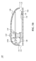
Fig. 1C shows thewire 140 received in thehousing 110, wherein thebase 120 is in the second position. Utilizing the embodiment of the invention, the wire and the joint are received in a chamber formed by thehousing 110 and thebase 120, and the joint (free end) of the wire is prevented from loosening, and the mouse is easily carried. In a modified example, the wire partially is wound up around theconnection pillar 132 to decrease the length of the wire exposed on the outside of the mouse. -
Fig. 2 shows a detailed structure of thefirst arm 1321, therestriction block 1313 and thefirst restriction slot 1311. As shown inFig. 2 , theconnection pillar 132 and theconnection element 131 are cylindrical. -
Figs. 3A and3B show a mouse 100' with a wire arrangement structure of a second embodiment of the invention. Themouse 100 comprises ahousing 110, abase 120 and awire 140. Thehousing 110 comprises anopening 111, anopening edge 112 and a connection element 131'. Thebase 120 comprises a connection pillar 132'. The connection pillar 132' is detachably connected to theconnection element 131. Thebase 120 corresponds to thehousing 110. When the connection pillar 132' is wedged to the connection element 131', thebase 120 abuts the openingedge 112 to cover theopening 111. When the connection pillar 132' is separated from the connection element 131', thebase 120 is separated from the openingedge 112 to uncover theopening 111. Thewire 140 comprises a joint 141, wherein when thewire 140 is in a receiving state, thewire 140 is wound up around the connection pillar 132'. - Similar to the first embodiment, the connection pillar 132' further comprises a
rib 1323. When thewire 140 is in the receiving state, thewire 140 is wound up around the connection pillar 132' between therib 1323 and thebase 120. - The characteristic of the mouse 100' of the second embodiment is that the connection pillar 132' is detachably connected to the connection element 131'. Utilizing the first and second embodiments of the invention, the wire and the joint are received in a chamber formed by the
housing 110 and thebase 120, and the joint (free end) of the wire is prevented from being loosened, and the mouse is easily carried. - Use of ordinal terms such as "first", "second", "third", etc., in the claims to modify a claim element does not by itself connote any priority, precedence, or order of one claim element over another or the temporal order in which acts of a method are performed, but are used merely as labels to distinguish one claim element having a certain name from another element having a same name (but for use of the ordinal term) to distinguish the claim elements.
- While the invention has been described by way of example and in terms of the preferred embodiments, it is to be understood that the invention is not limited to the disclosed embodiments. To the contrary, it is intended to cover various modifications and similar arrangements (as would be apparent to those skilled in the art). Therefore, the scope of the appended claims should be accorded the broadest interpretation so as to encompass all such modifications and similar arrangements.
Claims (10)
- A mouse with a wire arrangement structure, comprising:a housing, comprising an opening and an opening edge;a base, corresponding to the housing, wherein the base is moved between a first position and a second position, and when the base is in the first position, the base abuts the opening edge to cover the opening, and when the base is in the second position, the base is separated from the opening edge;a connection unit, connected to the housing and the base, allowing the base to move relative to the housing; anda wire, comprising a joint, wherein when the wire is in a receiving state, the wire is wound up around the connection unit.
- The mouse with a wire arrangement structure as claimed in claim 1, wherein the connection unit comprises a connection pillar and a connection element, and the connection pillar is disposed on the base, and the connection element is disposed on an inner surface of the housing, and the connection pillar is slidably connected to the connection element.
- The mouse with a wire arrangement structure as claimed in claim 2, further comprising a pushing element, wherein the connection element comprises a first restriction slot and a restriction block, and the connection pillar comprises a first arm, and when the base is in the first position, the restriction block abuts the first arm to restrict the connection pillar, and when the pushing element pushes the first arm, the first arm is deformed and separated from the restriction block and moved in the first restriction slot allowing the base moved toward the second position.
- The mouse with a wire arrangement structure as claimed in claim 3, wherein the connection element further comprises a second restriction slot, and the connection pillar further comprises a second arm, and the second arm slides in the second restriction slot.
- The mouse with a wire arrangement structure as claimed in claim 4, further comprising an elastic element, abutting the housing and the second arm.
- The mouse with a wire arrangement structure as claimed in claim 2, wherein the connection pillar further comprises a rib, and when the wire is in the receiving state, the wire is wound up around the connection pillar between the rib and the base.
- The mouse with a wire arrangement structure as claimed in claim 2, wherein the housing further comprises a notch formed on the opening edge, and when the wire is in a usage state, the wire abuts the notch.
- The mouse with a wire arrangement structure as claimed in claim 1, further comprising a joint fixer, disposed on the base, wherein when the wire is in the receiving state, the joint is wedged to the joint fixer.
- A mouse with a wire arrangement structure, comprising:a housing, comprising an opening, an opening edge and a connection element;a base, comprising a connection pillar, wherein the connection pillar is detachably connected to the connection element, and the base corresponds to the housing, and when the connection pillar is wedged to the connection element, the base abuts the opening edge to cover the opening, and when the connection pillar is separated from the connection element, the base is separated from the opening edge; anda wire, comprising a joint, wherein when the wire is in a receiving state, the wire is wound up around the connection unit.
- The mouse with a wire arrangement structure as claimed in claim 9, wherein the connection pillar further comprises a rib, and when the wire is in the receiving state, the wire is wound up around the connection pillar between the rib and the base.
Priority Applications (1)
| Application Number | Priority Date | Filing Date | Title |
|---|---|---|---|
| EP11151379A EP2479648A1 (en) | 2011-01-19 | 2011-01-19 | Mouse with wire arrangement structure |
Applications Claiming Priority (1)
| Application Number | Priority Date | Filing Date | Title |
|---|---|---|---|
| EP11151379A EP2479648A1 (en) | 2011-01-19 | 2011-01-19 | Mouse with wire arrangement structure |
Publications (1)
| Publication Number | Publication Date |
|---|---|
| EP2479648A1 true EP2479648A1 (en) | 2012-07-25 |
Family
ID=43731816
Family Applications (1)
| Application Number | Title | Priority Date | Filing Date |
|---|---|---|---|
| EP11151379A Withdrawn EP2479648A1 (en) | 2011-01-19 | 2011-01-19 | Mouse with wire arrangement structure |
Country Status (1)
| Country | Link |
|---|---|
| EP (1) | EP2479648A1 (en) |
Citations (6)
| Publication number | Priority date | Publication date | Assignee | Title |
|---|---|---|---|---|
| JPH03123926A (en) * | 1989-10-07 | 1991-05-27 | Canon Inc | pointing device |
| JP2000035855A (en) * | 1998-07-17 | 2000-02-02 | Sony Corp | mouse |
| JP2000105668A (en) * | 1998-07-31 | 2000-04-11 | Sony Corp | mouse |
| US6157370A (en) * | 1996-01-03 | 2000-12-05 | Softview Computer Products Corp. | Ergonomic mouse extension |
| US20020126092A1 (en) * | 2000-12-15 | 2002-09-12 | Logitech Europe S.A. | Adaptable input device support |
| US20030197684A1 (en) * | 2000-07-28 | 2003-10-23 | Smith David L. | Input device with cable storage |
-
2011
- 2011-01-19 EP EP11151379A patent/EP2479648A1/en not_active Withdrawn
Patent Citations (6)
| Publication number | Priority date | Publication date | Assignee | Title |
|---|---|---|---|---|
| JPH03123926A (en) * | 1989-10-07 | 1991-05-27 | Canon Inc | pointing device |
| US6157370A (en) * | 1996-01-03 | 2000-12-05 | Softview Computer Products Corp. | Ergonomic mouse extension |
| JP2000035855A (en) * | 1998-07-17 | 2000-02-02 | Sony Corp | mouse |
| JP2000105668A (en) * | 1998-07-31 | 2000-04-11 | Sony Corp | mouse |
| US20030197684A1 (en) * | 2000-07-28 | 2003-10-23 | Smith David L. | Input device with cable storage |
| US20020126092A1 (en) * | 2000-12-15 | 2002-09-12 | Logitech Europe S.A. | Adaptable input device support |
Similar Documents
| Publication | Publication Date | Title |
|---|---|---|
| JP6586341B2 (en) | Electronic device, pen, and pen holding method | |
| US10824206B2 (en) | Electronic device with external image-capturing module | |
| US8989372B2 (en) | Cover for mobile terminal | |
| US8493368B2 (en) | Stylus fixing assembly and electronic device using the same | |
| JP6009900B2 (en) | Pen-type input device and portable terminal equipped with the same | |
| US20110193826A1 (en) | Stylus | |
| JP4560052B2 (en) | Mobile device connection apparatus and system | |
| JP2011035810A (en) | Mobile terminal holder | |
| AU2018101268A4 (en) | A case for a tablet shaped device | |
| EP3048676A1 (en) | Connector structure and transmission line | |
| US8373681B2 (en) | Stylus having a retracted and extended position | |
| US20190235356A1 (en) | Device for operating a touchscreen and taking self-portraits | |
| US8358270B2 (en) | Mouse with wire arrangement structure | |
| CN103677332A (en) | Touch pen and mobile terminal with the touch pen | |
| US8059093B2 (en) | Wireless mouse having storing structure for storing wireless signal receiver therein | |
| US20070115618A1 (en) | System for housing writing instruments of different sizes in a portable computer | |
| CN102202113A (en) | Portable terminal device | |
| US8405643B2 (en) | Stylus | |
| US20130009874A1 (en) | Shape-changeable mouse | |
| US20110269005A1 (en) | Battery holder | |
| US20110139519A1 (en) | Stylus | |
| US20040095325A1 (en) | Computer keyboard | |
| US20220083097A1 (en) | Device accessories with attachment slots | |
| US20220374055A1 (en) | Electronic device with image-capturing function and shielding member thereof | |
| KR100810305B1 (en) | Stylus of information terminal |
Legal Events
| Date | Code | Title | Description |
|---|---|---|---|
| PUAI | Public reference made under article 153(3) epc to a published international application that has entered the european phase |
Free format text: ORIGINAL CODE: 0009012 |
|
| AK | Designated contracting states |
Kind code of ref document: A1 Designated state(s): AL AT BE BG CH CY CZ DE DK EE ES FI FR GB GR HR HU IE IS IT LI LT LU LV MC MK MT NL NO PL PT RO RS SE SI SK SM TR |
|
| AX | Request for extension of the european patent |
Extension state: BA ME |
|
| 17P | Request for examination filed |
Effective date: 20130112 |
|
| 17Q | First examination report despatched |
Effective date: 20130612 |
|
| RAP1 | Party data changed (applicant data changed or rights of an application transferred) |
Owner name: GIGA-BYTE TECHNOLOGY CO., LTD. |
|
| STAA | Information on the status of an ep patent application or granted ep patent |
Free format text: STATUS: THE APPLICATION IS DEEMED TO BE WITHDRAWN |
|
| 18D | Application deemed to be withdrawn |
Effective date: 20131023 |