EP2479641A1 - Mouse - Google Patents
Mouse Download PDFInfo
- Publication number
- EP2479641A1 EP2479641A1 EP11151383A EP11151383A EP2479641A1 EP 2479641 A1 EP2479641 A1 EP 2479641A1 EP 11151383 A EP11151383 A EP 11151383A EP 11151383 A EP11151383 A EP 11151383A EP 2479641 A1 EP2479641 A1 EP 2479641A1
- Authority
- EP
- European Patent Office
- Prior art keywords
- weight element
- mouse
- orientation
- contact
- housing
- Prior art date
- Legal status (The legal status is an assumption and is not a legal conclusion. Google has not performed a legal analysis and makes no representation as to the accuracy of the status listed.)
- Granted
Links
Images



Classifications
-
- G—PHYSICS
- G06—COMPUTING OR CALCULATING; COUNTING
- G06F—ELECTRIC DIGITAL DATA PROCESSING
- G06F1/00—Details not covered by groups G06F3/00 - G06F13/00 and G06F21/00
- G06F1/26—Power supply means, e.g. regulation thereof
- G06F1/32—Means for saving power
- G06F1/3203—Power management, i.e. event-based initiation of a power-saving mode
-
- G—PHYSICS
- G06—COMPUTING OR CALCULATING; COUNTING
- G06F—ELECTRIC DIGITAL DATA PROCESSING
- G06F1/00—Details not covered by groups G06F3/00 - G06F13/00 and G06F21/00
- G06F1/26—Power supply means, e.g. regulation thereof
- G06F1/32—Means for saving power
- G06F1/3203—Power management, i.e. event-based initiation of a power-saving mode
- G06F1/3234—Power saving characterised by the action undertaken
- G06F1/325—Power saving in peripheral device
- G06F1/3259—Power saving in cursor control device, e.g. mouse, joystick, trackball
-
- G—PHYSICS
- G06—COMPUTING OR CALCULATING; COUNTING
- G06F—ELECTRIC DIGITAL DATA PROCESSING
- G06F3/00—Input arrangements for transferring data to be processed into a form capable of being handled by the computer; Output arrangements for transferring data from processing unit to output unit, e.g. interface arrangements
- G06F3/01—Input arrangements or combined input and output arrangements for interaction between user and computer
- G06F3/03—Arrangements for converting the position or the displacement of a member into a coded form
- G06F3/033—Pointing devices displaced or positioned by the user, e.g. mice, trackballs, pens or joysticks; Accessories therefor
- G06F3/0354—Pointing devices displaced or positioned by the user, e.g. mice, trackballs, pens or joysticks; Accessories therefor with detection of two-dimensional [2D] relative movements between the device, or an operating part thereof, and a plane or surface, e.g. 2D mice, trackballs, pens or pucks
- G06F3/03543—Mice or pucks
-
- H—ELECTRICITY
- H01—ELECTRIC ELEMENTS
- H01H—ELECTRIC SWITCHES; RELAYS; SELECTORS; EMERGENCY PROTECTIVE DEVICES
- H01H35/00—Switches operated by change of a physical condition
- H01H35/02—Switches operated by change of position, inclination or orientation of the switch itself in relation to gravitational field
-
- Y—GENERAL TAGGING OF NEW TECHNOLOGICAL DEVELOPMENTS; GENERAL TAGGING OF CROSS-SECTIONAL TECHNOLOGIES SPANNING OVER SEVERAL SECTIONS OF THE IPC; TECHNICAL SUBJECTS COVERED BY FORMER USPC CROSS-REFERENCE ART COLLECTIONS [XRACs] AND DIGESTS
- Y02—TECHNOLOGIES OR APPLICATIONS FOR MITIGATION OR ADAPTATION AGAINST CLIMATE CHANGE
- Y02D—CLIMATE CHANGE MITIGATION TECHNOLOGIES IN INFORMATION AND COMMUNICATION TECHNOLOGIES [ICT], I.E. INFORMATION AND COMMUNICATION TECHNOLOGIES AIMING AT THE REDUCTION OF THEIR OWN ENERGY USE
- Y02D10/00—Energy efficient computing, e.g. low power processors, power management or thermal management
Definitions
- the present invention relates to a mouse, and in particular relates to a wireless mouse which has decreased power consumption.
- a conventional wireless mouse is automatically deactivated only when the key of the wireless mouse has not been pressed for a long period of time. Thus, a relatively large amount of power is consumed during the long period of time, shortening the time for battery power usage of the wireless mouse. Therefore, a wireless mouse with decreased power consumption is required.
- a mouse adapted to stand or lie on a supporting surface includes a housing, a power source and a power switch unit.
- the power source is disposed in the housing.
- the power switch unit is disposed in the housing, the power switch unit includes a pivot shaft, a weight element and a switch circuit board.
- the weight element pivots on the pivot shaft, wherein the weight element pivots between a first orientation and a second orientation, and when the mouse is placed standing on the supporting surface, the weight element is in the first orientation, and when the mouse lies on the supporting surface, the weight element is in the second orientation.
- the switch circuit board is electrically connected to the power source, wherein the switch circuit board comprises a first contact and a second contact, and when the weight element is in the second orientation, the weight element electrically connects the first contact to the second contact to turn on the mouse, and when the weight element is in the first orientation, the weight element is separated from the first contact and the second contact.
- the power switch unit turns off the mouse automatically when the mouse is placed standing on a supporting surface. Accordingly, power consumption of the power source (battery unit) of the mouse is saved, and battery power usage of the mouse is extended.
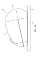
- Fig. 1A shows a mouse of a first embodiment of the invention standing on a supporting surface (table);
- Fig. 1B shows the mouse of the first embodiment of the invention lying on the supporting surface (table);
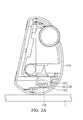
- Fig. 2A is a sectional view of the mouse in Fig. 1A ;
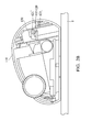
- Fig. 2B is a sectional view of the mouse in Fig. 1B ;
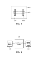
- Fig. 3 shows a detailed structure of a switch circuit board of the first embodiment of the invention
- Fig. 4 is a block diagram of the mouse of the first embodiment of the invention.
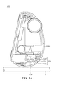
- Figs. 5A and 5B show a mouse of a second embodiment of the invention
- Figs. 6A and 6B show a mouse of a third embodiment of the invention.
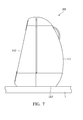
- Fig. 7 shows a mouse of a fourth embodiment of the invention.
- Figs. 1A and 1B show a mouse 100 of a first embodiment of the invention.
- Fig. 1A shows the mouse 100 of the first embodiment standing on a supporting surface (table).
- Fig. 1B shows the mouse 100 of the first embodiment lying on the supporting surface (table).
- Fig. 2A is a sectional view of the mouse 100 in Fig. 1A .
- Fig. 2B is a sectional view of the mouse 100 in Fig. 1B .
- the mouse 100 comprises a housing 110, a power source (not shown) and a power switch unit 120.
- the power source is disposed in the housing 110.
- the power switch unit 120 is disposed in the housing 110.
- the power switch unit 120 comprises a pivot shaft 121, a weight element 122 and switch circuit board 123.
- the weight element 122 pivots on the pivot shaft 121, wherein the weight element 122 pivots between a first orientation (as shown in Fig. 2A ) and a second orientation (as shown in Fig. 2B ).
- a first orientation as shown in Fig. 2A
- a second orientation as shown in Fig. 2B
- the switch circuit board 123 is electrically connected to the power source.
- the switch circuit board 123 comprises a first contact 1231 and a second contact 1232.
- the weight element 122 When the weight element 122 is in the second orientation, the weight element 122 electrically connects the first contact 1231 to the second contact 1232 to turn on the mouse 100.
- the weight element 122 In Fig. 3 , the weight element 122 is shown as a dotted line. With reference to Figs. 2A , 2B and 3 , the weight element 122 is L shaped, an end of the weight element 122 pivots on the pivot shaft 121, and when the weight element 122 is in the second orientation, the other end of the weight element 122 contacts the first contact 1231 and the second contact 1232.
- the mouse 100 further comprises a barricade 130, wherein when the weight element 122 is in the first orientation, the weight element 122 abuts the barricade 130.
- the poured source 140 is electrically connected to the switch circuit board 123 of the power switch unit 120.
- the switch circuit board 123 is electrically connected to a mouse circuit board 150. When the mouse is turned on, the electric power provided by the power source 140 passes through the switch circuit board 123 to the mouse circuit board 150.
- the housing 110 further comprises a holding portion 111, a sliding portion 112 and a standing portion 113, wherein the standing portion 113 is connected to the holding portion 111 and the sliding portion 112, and the standing portion 113 is curved.
- the center-of-gravity of the mouse 100 can be designed adjacent to the standing portion 113 to keep the mouse 100 standing similar to tumbler (toy).
- the battery unit (power source) of the mouse 100 can be disposed in the housing 100 adjacent to the standing portion 113, or an additional weight can be disposed adjacent to the standing portion 113.
- Figs. 5A and 5B show a mouse 101 of a second embodiment of the invention, wherein the switch circuit board 123 is replaced by a switch element 123'.
- the switch element 123' can be a contact switch or other switches.
- Figs. 6A and 6B show a mouse 103 of a third embodiment of the invention, wherein the switch circuit board 123 is omitted.
- a first contact 1231 and a second contact 1232 are disposed on the pivot shaft 121.
- the weight element 122 comprises a conductive pad 1221. When the weight element 122 is in the second orientation, the conductive pad 1221 electrically connects the first contact 1231 to the second contact 1232 to turn on the mouse.
- the mouse 102 of the third embodiment can further comprise a barricade 130' to restrict the rotation orientation of the weight element 122.
- Fig. 7 shows a mouse 103 of a fourth embodiment of the invention, wherein the standing portion 113' is planar, allowing the mouse 103 to stand therewith.
- the embodiment of Fig. 7 can be incorporated with any embodiment previously mentioned in this ?.
- the power switch unit turns off the mouse automatically when the mouse is placed standing on the supporting surface. Accordingly, power consumption of the power source (battery unit) of the mouse is saved, and battery power usage of the mouse is extended.
Landscapes
- Engineering & Computer Science (AREA)
- Theoretical Computer Science (AREA)
- General Engineering & Computer Science (AREA)
- Physics & Mathematics (AREA)
- General Physics & Mathematics (AREA)
- Human Computer Interaction (AREA)
- Position Input By Displaying (AREA)
Abstract
Description
- The present invention relates to a mouse, and in particular relates to a wireless mouse which has decreased power consumption.
- A conventional wireless mouse is automatically deactivated only when the key of the wireless mouse has not been pressed for a long period of time. Thus, a relatively large amount of power is consumed during the long period of time, shortening the time for battery power usage of the wireless mouse. Therefore, a wireless mouse with decreased power consumption is required.
- A mouse adapted to stand or lie on a supporting surface is provided. The mouse includes a housing, a power source and a power switch unit. The power source is disposed in the housing. The power switch unit is disposed in the housing, the power switch unit includes a pivot shaft, a weight element and a switch circuit board. The weight element pivots on the pivot shaft, wherein the weight element pivots between a first orientation and a second orientation, and when the mouse is placed standing on the supporting surface, the weight element is in the first orientation, and when the mouse lies on the supporting surface, the weight element is in the second orientation. The switch circuit board is electrically connected to the power source, wherein the switch circuit board comprises a first contact and a second contact, and when the weight element is in the second orientation, the weight element electrically connects the first contact to the second contact to turn on the mouse, and when the weight element is in the first orientation, the weight element is separated from the first contact and the second contact.
- When utilizing the mouse of the embodiments of the invention, the power switch unit turns off the mouse automatically when the mouse is placed standing on a supporting surface. Accordingly, power consumption of the power source (battery unit) of the mouse is saved, and battery power usage of the mouse is extended.
- A detailed description is given in the following embodiments with reference to the accompanying drawings.
- The present invention can be more fully understood by reading the subsequent detailed description and examples with references made to the accompanying drawings, wherein:
-
Fig. 1A shows a mouse of a first embodiment of the invention standing on a supporting surface (table); -
Fig. 1B shows the mouse of the first embodiment of the invention lying on the supporting surface (table); -
Fig. 2A is a sectional view of the mouse inFig. 1A ; -
Fig. 2B is a sectional view of the mouse inFig. 1B ; -
Fig. 3 shows a detailed structure of a switch circuit board of the first embodiment of the invention; -
Fig. 4 is a block diagram of the mouse of the first embodiment of the invention; -
Figs. 5A and5B show a mouse of a second embodiment of the invention; -
Figs. 6A and6B show a mouse of a third embodiment of the invention; and -
Fig. 7 shows a mouse of a fourth embodiment of the invention. - The following description is of the best-contemplated mode of carrying out the invention. This description is made for the purpose of illustrating the general principles of the invention and should not be taken in a limiting sense. The scope of the invention is best determined by reference to the appended claims.
-
Figs. 1A and1B show amouse 100 of a first embodiment of the invention.Fig. 1A shows themouse 100 of the first embodiment standing on a supporting surface (table).Fig. 1B shows themouse 100 of the first embodiment lying on the supporting surface (table).Fig. 2A is a sectional view of themouse 100 inFig. 1A .Fig. 2B is a sectional view of themouse 100 inFig. 1B . With reference toFigs. 2A and2B , themouse 100 comprises ahousing 110, a power source (not shown) and apower switch unit 120. The power source is disposed in thehousing 110. Thepower switch unit 120 is disposed in thehousing 110. Thepower switch unit 120 comprises apivot shaft 121, aweight element 122 andswitch circuit board 123. Theweight element 122 pivots on thepivot shaft 121, wherein theweight element 122 pivots between a first orientation (as shown inFig. 2A ) and a second orientation (as shown inFig. 2B ). When themouse 100 stands on the supporting surface, theweight element 122 is in the first orientation, and when themouse 100 lies on the supporting surface, theweight element 122 pivots to the second orientation. Theswitch circuit board 123 is electrically connected to the power source. With reference toFig. 3 , theswitch circuit board 123 comprises afirst contact 1231 and asecond contact 1232. When theweight element 122 is in the second orientation, theweight element 122 electrically connects thefirst contact 1231 to thesecond contact 1232 to turn on themouse 100. InFig. 3 , theweight element 122 is shown as a dotted line. With reference toFigs. 2A ,2B and3 , theweight element 122 is L shaped, an end of theweight element 122 pivots on thepivot shaft 121, and when theweight element 122 is in the second orientation, the other end of theweight element 122 contacts thefirst contact 1231 and thesecond contact 1232. - With reference to
Figs. 2A and2B , themouse 100 further comprises abarricade 130, wherein when theweight element 122 is in the first orientation, theweight element 122 abuts thebarricade 130. - With reference to
Fig. 4 , the pouredsource 140 is electrically connected to theswitch circuit board 123 of thepower switch unit 120. Theswitch circuit board 123 is electrically connected to amouse circuit board 150. When the mouse is turned on, the electric power provided by thepower source 140 passes through theswitch circuit board 123 to themouse circuit board 150. - With reference to
Figs. 1A and1B , thehousing 110 further comprises a holdingportion 111, a slidingportion 112 and a standingportion 113, wherein the standingportion 113 is connected to the holdingportion 111 and the slidingportion 112, and the standingportion 113 is curved. In this embodiment, the center-of-gravity of themouse 100 can be designed adjacent to the standingportion 113 to keep themouse 100 standing similar to tumbler (toy). For example, the battery unit (power source) of themouse 100 can be disposed in thehousing 100 adjacent to the standingportion 113, or an additional weight can be disposed adjacent to the standingportion 113. -
Figs. 5A and5B show amouse 101 of a second embodiment of the invention, wherein theswitch circuit board 123 is replaced by a switch element 123'. When theweight element 122 is in the second orientation, theweight element 122 presses the switch element 123' to turn on the mouse. The switch element 123' can be a contact switch or other switches. -
Figs. 6A and6B show amouse 103 of a third embodiment of the invention, wherein theswitch circuit board 123 is omitted. Afirst contact 1231 and asecond contact 1232 are disposed on thepivot shaft 121. Theweight element 122 comprises aconductive pad 1221. When theweight element 122 is in the second orientation, theconductive pad 1221 electrically connects thefirst contact 1231 to thesecond contact 1232 to turn on the mouse. Additionally, themouse 102 of the third embodiment can further comprise a barricade 130' to restrict the rotation orientation of theweight element 122. -
Fig. 7 shows amouse 103 of a fourth embodiment of the invention, wherein the standing portion 113' is planar, allowing themouse 103 to stand therewith. The embodiment ofFig. 7 can be incorporated with any embodiment previously mentioned in this ?. - When utilizing the mouse of the embodiments of the invention, the power switch unit turns off the mouse automatically when the mouse is placed standing on the supporting surface. Accordingly, power consumption of the power source (battery unit) of the mouse is saved, and battery power usage of the mouse is extended.
- The use of ordinal terms such as "first", "second", "third", etc., in the claims to modify a claim element does not by itself connote any priority, precedence, or order of one claim element over another or the temporal order in which acts of a method are performed, but are used merely as labels to distinguish one claim element having a certain name from another element having a same name (but for use of the ordinal term) to distinguish the claim elements.
- While the invention has been described by way of example and in terms of the preferred embodiments, it is to be understood that the invention is not limited to the disclosed embodiments. To the contrary, it is intended to cover various modifications and similar arrangements (as would be apparent to those skilled in the art). Therefore, the scope of the appended claims should be accorded the broadest interpretation so as to encompass all such modifications and similar arrangements.
Claims (18)
- A mouse adapted to stand or lie on a supporting surface, comprising:a housing;a power source, disposed in the housing; anda power switch unit, disposed in the housing, comprising:a pivot shaft;a weight element, pivoting on the pivot shaft, wherein the weight element pivots between a first orientation and a second orientation, and when the mouse is placed standing on the supporting surface, the weight element is in the first orientation, and when the mouse lies on the supporting surface, the weight element is in the second orientation; anda switch circuit board, electrically connected to the power source, wherein the switch circuit board comprises a first contact and a second contact, and when the weight element is in the second orientation, the weight element electrically connects the first contact to the second contact to turn on the mouse, and when the weight element is in the first orientation, the weight element is separated from the first contact and the second contact.
- The mouse as claimed in claim 1, wherein the weight element is L shaped, and an end of the weight element pivots on the pivot shaft, and when the weight element is in the second orientation, the other end of the weight element contacts the first contact and the second contact.
- The mouse as claimed in claim 1, further comprising a barricade, wherein when the weight element is in the first orientation, the weight element abuts the barricade.
- The mouse as claimed in claim 1, wherein the housing further comprises a holding portion, a sliding portion and a standing portion, wherein the standing portion is connected to the holding portion and the sliding portion, and the standing portion is curved.
- The mouse as claimed in claim 4, further comprising a battery unit, wherein the battery unit is disposed in the housing and is adjacent to the standing portion.
- The mouse as claimed in claim 1, wherein the housing further comprises a holding portion, a sliding portion and a standing portion, and the standing portion is connected to the holding portion and the sliding portion, and the standing portion is planar.
- A mouse adapted to stand or lie on a supporting surface, comprising:a housing;a power source, disposed in the housing; anda power switch unit, disposed in the housing, comprising:a pivot shaft;a weight element, pivoting on the pivot shaft, wherein the weight
element pivots between a first orientation and a second orientation, and when the mouse is placed standing on the supporting surface, the weight element is in the first orientation, and when the mouse lies on the supporting surface, the weight element is in the second orientation; anda switch element, electrically connected to the power source, wherein
when the weight element is in the second orientation, the weight element presses the switch element to turn on the mouse, and when the weight element is in the first orientation, the weight element is separated from the switch element. - The mouse as claimed in claim 7, wherein the weight element is L shaped, an end of the weight element pivots on the pivot shaft, and when the weight element is in the second orientation, the other end of the weight element presses the switch element.
- The mouse as claimed in claim 7, further comprising a barricade, wherein when the weight element is in the first orientation, the weight element abuts the barricade.
- The mouse as claimed in claim 7, wherein the housing further comprises a holding portion, a sliding portion and a standing portion, and the standing portion is connected to the holding portion and the sliding portion, and the standing portion is curved.
- The mouse as claimed in claim 10, further comprising a battery unit, wherein the battery unit is disposed in the housing and is adjacent to the standing portion.
- The mouse as claimed in claim 7, wherein the housing further comprises a holding portion, a sliding portion and a standing portion, and the standing portion is connected to the holding portion and the sliding portion, and the standing portion is planar.
- A mouse adapted to stand or lie on a supporting surface, comprising:a housing;a power source, disposed in the housing; anda power switch unit, disposed in the housing, comprising:a pivot shaft;a weight element, pivoting on the pivot shaft, wherein the weight
element pivots between a first orientation and a second orientation, and when the mouse is placed standing on the supporting surface, the weight element is in the first orientation, and when the mouse lies on the supporting surface, the weight element is in the second orientation;a first contact, disposed on the pivot shaft; anda second contact, disposed on the pivot shaft, wherein when the weight
element is in the second orientation, the weight element electrically connects the first contact to the second contact to turn on the mouse. - The mouse as claimed in claim 13, wherein the weight element is L shaped, an end of the weight element pivots on the pivot shaft, and the weight element comprises a conductive pad, and when the weight element is in the second orientation, the conductive pad electrically contacts the first contact to the second contact.
- The mouse as claimed in claim 13, further comprising a barricade, wherein when the weight element is in the first orientation, the weight element abuts the barricade.
- The mouse as claimed in claim 13, wherein the housing further comprises a holding portion, a sliding portion and a standing portion, and the standing portion is connected to the holding portion and the sliding portion, and the standing portion is curved.
- The mouse as claimed in claim 16, further comprising a battery unit, wherein the battery unit is disposed in the housing and is adjacent to the standing portion.
- The mouse as claimed in claim 13, wherein the housing further comprises a holding portion, a sliding portion and a standing portion, and the standing portion is connected to the holding portion and the sliding portion, and the standing portion is planar.
Priority Applications (1)
| Application Number | Priority Date | Filing Date | Title |
|---|---|---|---|
| EP11151383.4A EP2479641B1 (en) | 2011-01-19 | 2011-01-19 | Mouse |
Applications Claiming Priority (1)
| Application Number | Priority Date | Filing Date | Title |
|---|---|---|---|
| EP11151383.4A EP2479641B1 (en) | 2011-01-19 | 2011-01-19 | Mouse |
Publications (2)
| Publication Number | Publication Date |
|---|---|
| EP2479641A1 true EP2479641A1 (en) | 2012-07-25 |
| EP2479641B1 EP2479641B1 (en) | 2017-03-01 |
Family
ID=44074680
Family Applications (1)
| Application Number | Title | Priority Date | Filing Date |
|---|---|---|---|
| EP11151383.4A Not-in-force EP2479641B1 (en) | 2011-01-19 | 2011-01-19 | Mouse |
Country Status (1)
| Country | Link |
|---|---|
| EP (1) | EP2479641B1 (en) |
Families Citing this family (1)
| Publication number | Priority date | Publication date | Assignee | Title |
|---|---|---|---|---|
| AU2020484403A1 (en) | 2020-12-31 | 2023-08-10 | Razer (Asia-Pacific) Pte. Ltd. | Battery-operated handheld device |
Citations (2)
| Publication number | Priority date | Publication date | Assignee | Title |
|---|---|---|---|---|
| WO2000025196A1 (en) * | 1998-10-27 | 2000-05-04 | Glaser Lawerence F | Computer pointing device having theme identification means |
| US6104009A (en) * | 1998-12-07 | 2000-08-15 | Hp Intellectual Corp. | Electrical appliance having user proximity sensor |
Family Cites Families (2)
| Publication number | Priority date | Publication date | Assignee | Title |
|---|---|---|---|---|
| US6492975B1 (en) * | 2000-10-03 | 2002-12-10 | Josef Weiss | Computer mouse |
| US20020166756A1 (en) * | 2001-05-14 | 2002-11-14 | Thompson Mitchell Lee | Tilt sensor |
-
2011
- 2011-01-19 EP EP11151383.4A patent/EP2479641B1/en not_active Not-in-force
Patent Citations (2)
| Publication number | Priority date | Publication date | Assignee | Title |
|---|---|---|---|---|
| WO2000025196A1 (en) * | 1998-10-27 | 2000-05-04 | Glaser Lawerence F | Computer pointing device having theme identification means |
| US6104009A (en) * | 1998-12-07 | 2000-08-15 | Hp Intellectual Corp. | Electrical appliance having user proximity sensor |
Also Published As
| Publication number | Publication date |
|---|---|
| EP2479641B1 (en) | 2017-03-01 |
Similar Documents
| Publication | Publication Date | Title |
|---|---|---|
| US20040264720A1 (en) | Wireless earphone having replaceable battery module | |
| CN201639740U (en) | Bluetooth headset for portable terminal | |
| US7773038B2 (en) | Electronic devices with antenna sensors | |
| CN108183045B (en) | electronic device | |
| GB2437435B (en) | Handheld penknife-like laryngoscope | |
| WO2004089186A3 (en) | Handpiece with rf electrode and non-volatile memory | |
| US20120188161A1 (en) | Mouse | |
| EP1647923A3 (en) | Socket for memory card | |
| KR20040067826A (en) | An antenna device and a portable wireless communication apparatus | |
| TW200608665A (en) | Battery circuit with non-volitable memory and thermistor on a single line | |
| EP2479641B1 (en) | Mouse | |
| US20100178542A1 (en) | Electronic device | |
| CN106814598B (en) | A kind of smartwatch | |
| JP3224353U (en) | Mobile phone holder for wireless charging | |
| JP2000269849A5 (en) | ||
| US20030069050A1 (en) | Portable electronic system equipped with a spare battery device | |
| US8794557B2 (en) | Electric seasoning mill | |
| US10875439B2 (en) | Split-type car cigarette lighter | |
| CN202736800U (en) | Button switch | |
| KR101967158B1 (en) | Case for Mobile Device for Easy Attach and Detach Accessories | |
| JP2001320212A (en) | Radio card | |
| CN210203828U (en) | Rotary socket table | |
| JP5284379B2 (en) | mouse | |
| TW200606520A (en) | Panel unit capable of avoiding contact between electrically conductive bodies thereon | |
| US8750800B2 (en) | Bluetooth dedvice |
Legal Events
| Date | Code | Title | Description |
|---|---|---|---|
| PUAI | Public reference made under article 153(3) epc to a published international application that has entered the european phase |
Free format text: ORIGINAL CODE: 0009012 |
|
| AK | Designated contracting states |
Kind code of ref document: A1 Designated state(s): AL AT BE BG CH CY CZ DE DK EE ES FI FR GB GR HR HU IE IS IT LI LT LU LV MC MK MT NL NO PL PT RO RS SE SI SK SM TR |
|
| AX | Request for extension of the european patent |
Extension state: BA ME |
|
| 17P | Request for examination filed |
Effective date: 20130112 |
|
| 17Q | First examination report despatched |
Effective date: 20130611 |
|
| RAP1 | Party data changed (applicant data changed or rights of an application transferred) |
Owner name: GIGA-BYTE TECHNOLOGY CO., LTD. |
|
| GRAP | Despatch of communication of intention to grant a patent |
Free format text: ORIGINAL CODE: EPIDOSNIGR1 |
|
| INTG | Intention to grant announced |
Effective date: 20161027 |
|
| RIN1 | Information on inventor provided before grant (corrected) |
Inventor name: CHEN, SHU-I Inventor name: SHIH, PO-JEN |
|
| STAA | Information on the status of an ep patent application or granted ep patent |
Free format text: STATUS: GRANT OF PATENT IS INTENDED |
|
| GRAS | Grant fee paid |
Free format text: ORIGINAL CODE: EPIDOSNIGR3 |
|
| GRAA | (expected) grant |
Free format text: ORIGINAL CODE: 0009210 |
|
| STAA | Information on the status of an ep patent application or granted ep patent |
Free format text: STATUS: THE PATENT HAS BEEN GRANTED |
|
| AK | Designated contracting states |
Kind code of ref document: B1 Designated state(s): AL AT BE BG CH CY CZ DE DK EE ES FI FR GB GR HR HU IE IS IT LI LT LU LV MC MK MT NL NO PL PT RO RS SE SI SK SM TR |
|
| REG | Reference to a national code |
Ref country code: GB Ref legal event code: FG4D |
|
| REG | Reference to a national code |
Ref country code: CH Ref legal event code: EP Ref country code: AT Ref legal event code: REF Ref document number: 872075 Country of ref document: AT Kind code of ref document: T Effective date: 20170315 |
|
| REG | Reference to a national code |
Ref country code: IE Ref legal event code: FG4D |
|
| REG | Reference to a national code |
Ref country code: DE Ref legal event code: R096 Ref document number: 602011035352 Country of ref document: DE |
|
| REG | Reference to a national code |
Ref country code: NL Ref legal event code: FP |
|
| REG | Reference to a national code |
Ref country code: LT Ref legal event code: MG4D |
|
| REG | Reference to a national code |
Ref country code: AT Ref legal event code: MK05 Ref document number: 872075 Country of ref document: AT Kind code of ref document: T Effective date: 20170301 |
|
| PG25 | Lapsed in a contracting state [announced via postgrant information from national office to epo] |
Ref country code: GR Free format text: LAPSE BECAUSE OF FAILURE TO SUBMIT A TRANSLATION OF THE DESCRIPTION OR TO PAY THE FEE WITHIN THE PRESCRIBED TIME-LIMIT Effective date: 20170602 Ref country code: HR Free format text: LAPSE BECAUSE OF FAILURE TO SUBMIT A TRANSLATION OF THE DESCRIPTION OR TO PAY THE FEE WITHIN THE PRESCRIBED TIME-LIMIT Effective date: 20170301 Ref country code: LT Free format text: LAPSE BECAUSE OF FAILURE TO SUBMIT A TRANSLATION OF THE DESCRIPTION OR TO PAY THE FEE WITHIN THE PRESCRIBED TIME-LIMIT Effective date: 20170301 Ref country code: NO Free format text: LAPSE BECAUSE OF FAILURE TO SUBMIT A TRANSLATION OF THE DESCRIPTION OR TO PAY THE FEE WITHIN THE PRESCRIBED TIME-LIMIT Effective date: 20170601 Ref country code: FI Free format text: LAPSE BECAUSE OF FAILURE TO SUBMIT A TRANSLATION OF THE DESCRIPTION OR TO PAY THE FEE WITHIN THE PRESCRIBED TIME-LIMIT Effective date: 20170301 |
|
| PG25 | Lapsed in a contracting state [announced via postgrant information from national office to epo] |
Ref country code: LV Free format text: LAPSE BECAUSE OF FAILURE TO SUBMIT A TRANSLATION OF THE DESCRIPTION OR TO PAY THE FEE WITHIN THE PRESCRIBED TIME-LIMIT Effective date: 20170301 Ref country code: RS Free format text: LAPSE BECAUSE OF FAILURE TO SUBMIT A TRANSLATION OF THE DESCRIPTION OR TO PAY THE FEE WITHIN THE PRESCRIBED TIME-LIMIT Effective date: 20170301 Ref country code: ES Free format text: LAPSE BECAUSE OF FAILURE TO SUBMIT A TRANSLATION OF THE DESCRIPTION OR TO PAY THE FEE WITHIN THE PRESCRIBED TIME-LIMIT Effective date: 20170301 Ref country code: AT Free format text: LAPSE BECAUSE OF FAILURE TO SUBMIT A TRANSLATION OF THE DESCRIPTION OR TO PAY THE FEE WITHIN THE PRESCRIBED TIME-LIMIT Effective date: 20170301 Ref country code: BG Free format text: LAPSE BECAUSE OF FAILURE TO SUBMIT A TRANSLATION OF THE DESCRIPTION OR TO PAY THE FEE WITHIN THE PRESCRIBED TIME-LIMIT Effective date: 20170601 Ref country code: SE Free format text: LAPSE BECAUSE OF FAILURE TO SUBMIT A TRANSLATION OF THE DESCRIPTION OR TO PAY THE FEE WITHIN THE PRESCRIBED TIME-LIMIT Effective date: 20170301 |
|
| PG25 | Lapsed in a contracting state [announced via postgrant information from national office to epo] |
Ref country code: RO Free format text: LAPSE BECAUSE OF FAILURE TO SUBMIT A TRANSLATION OF THE DESCRIPTION OR TO PAY THE FEE WITHIN THE PRESCRIBED TIME-LIMIT Effective date: 20170301 Ref country code: EE Free format text: LAPSE BECAUSE OF FAILURE TO SUBMIT A TRANSLATION OF THE DESCRIPTION OR TO PAY THE FEE WITHIN THE PRESCRIBED TIME-LIMIT Effective date: 20170301 Ref country code: SK Free format text: LAPSE BECAUSE OF FAILURE TO SUBMIT A TRANSLATION OF THE DESCRIPTION OR TO PAY THE FEE WITHIN THE PRESCRIBED TIME-LIMIT Effective date: 20170301 Ref country code: CZ Free format text: LAPSE BECAUSE OF FAILURE TO SUBMIT A TRANSLATION OF THE DESCRIPTION OR TO PAY THE FEE WITHIN THE PRESCRIBED TIME-LIMIT Effective date: 20170301 |
|
| PG25 | Lapsed in a contracting state [announced via postgrant information from national office to epo] |
Ref country code: IS Free format text: LAPSE BECAUSE OF FAILURE TO SUBMIT A TRANSLATION OF THE DESCRIPTION OR TO PAY THE FEE WITHIN THE PRESCRIBED TIME-LIMIT Effective date: 20170701 Ref country code: PL Free format text: LAPSE BECAUSE OF FAILURE TO SUBMIT A TRANSLATION OF THE DESCRIPTION OR TO PAY THE FEE WITHIN THE PRESCRIBED TIME-LIMIT Effective date: 20170301 Ref country code: SM Free format text: LAPSE BECAUSE OF FAILURE TO SUBMIT A TRANSLATION OF THE DESCRIPTION OR TO PAY THE FEE WITHIN THE PRESCRIBED TIME-LIMIT Effective date: 20170301 Ref country code: PT Free format text: LAPSE BECAUSE OF FAILURE TO SUBMIT A TRANSLATION OF THE DESCRIPTION OR TO PAY THE FEE WITHIN THE PRESCRIBED TIME-LIMIT Effective date: 20170703 |
|
| REG | Reference to a national code |
Ref country code: DE Ref legal event code: R097 Ref document number: 602011035352 Country of ref document: DE |
|
| REG | Reference to a national code |
Ref country code: FR Ref legal event code: PLFP Year of fee payment: 8 |
|
| PLBE | No opposition filed within time limit |
Free format text: ORIGINAL CODE: 0009261 |
|
| STAA | Information on the status of an ep patent application or granted ep patent |
Free format text: STATUS: NO OPPOSITION FILED WITHIN TIME LIMIT |
|
| PG25 | Lapsed in a contracting state [announced via postgrant information from national office to epo] |
Ref country code: DK Free format text: LAPSE BECAUSE OF FAILURE TO SUBMIT A TRANSLATION OF THE DESCRIPTION OR TO PAY THE FEE WITHIN THE PRESCRIBED TIME-LIMIT Effective date: 20170301 |
|
| 26N | No opposition filed |
Effective date: 20171204 |
|
| PG25 | Lapsed in a contracting state [announced via postgrant information from national office to epo] |
Ref country code: IT Free format text: LAPSE BECAUSE OF FAILURE TO SUBMIT A TRANSLATION OF THE DESCRIPTION OR TO PAY THE FEE WITHIN THE PRESCRIBED TIME-LIMIT Effective date: 20170301 Ref country code: SI Free format text: LAPSE BECAUSE OF FAILURE TO SUBMIT A TRANSLATION OF THE DESCRIPTION OR TO PAY THE FEE WITHIN THE PRESCRIBED TIME-LIMIT Effective date: 20170301 |
|
| REG | Reference to a national code |
Ref country code: CH Ref legal event code: PL |
|
| PG25 | Lapsed in a contracting state [announced via postgrant information from national office to epo] |
Ref country code: LU Free format text: LAPSE BECAUSE OF NON-PAYMENT OF DUE FEES Effective date: 20180119 |
|
| REG | Reference to a national code |
Ref country code: IE Ref legal event code: MM4A |
|
| REG | Reference to a national code |
Ref country code: BE Ref legal event code: MM Effective date: 20180131 |
|
| PG25 | Lapsed in a contracting state [announced via postgrant information from national office to epo] |
Ref country code: BE Free format text: LAPSE BECAUSE OF NON-PAYMENT OF DUE FEES Effective date: 20180131 Ref country code: CH Free format text: LAPSE BECAUSE OF NON-PAYMENT OF DUE FEES Effective date: 20180131 Ref country code: LI Free format text: LAPSE BECAUSE OF NON-PAYMENT OF DUE FEES Effective date: 20180131 |
|
| PG25 | Lapsed in a contracting state [announced via postgrant information from national office to epo] |
Ref country code: IE Free format text: LAPSE BECAUSE OF NON-PAYMENT OF DUE FEES Effective date: 20180119 |
|
| PG25 | Lapsed in a contracting state [announced via postgrant information from national office to epo] |
Ref country code: MC Free format text: LAPSE BECAUSE OF FAILURE TO SUBMIT A TRANSLATION OF THE DESCRIPTION OR TO PAY THE FEE WITHIN THE PRESCRIBED TIME-LIMIT Effective date: 20170301 |
|
| PG25 | Lapsed in a contracting state [announced via postgrant information from national office to epo] |
Ref country code: MT Free format text: LAPSE BECAUSE OF NON-PAYMENT OF DUE FEES Effective date: 20180119 |
|
| PG25 | Lapsed in a contracting state [announced via postgrant information from national office to epo] |
Ref country code: TR Free format text: LAPSE BECAUSE OF FAILURE TO SUBMIT A TRANSLATION OF THE DESCRIPTION OR TO PAY THE FEE WITHIN THE PRESCRIBED TIME-LIMIT Effective date: 20170301 |
|
| PG25 | Lapsed in a contracting state [announced via postgrant information from national office to epo] |
Ref country code: HU Free format text: LAPSE BECAUSE OF FAILURE TO SUBMIT A TRANSLATION OF THE DESCRIPTION OR TO PAY THE FEE WITHIN THE PRESCRIBED TIME-LIMIT; INVALID AB INITIO Effective date: 20110119 |
|
| PG25 | Lapsed in a contracting state [announced via postgrant information from national office to epo] |
Ref country code: MK Free format text: LAPSE BECAUSE OF NON-PAYMENT OF DUE FEES Effective date: 20170301 Ref country code: CY Free format text: LAPSE BECAUSE OF FAILURE TO SUBMIT A TRANSLATION OF THE DESCRIPTION OR TO PAY THE FEE WITHIN THE PRESCRIBED TIME-LIMIT Effective date: 20170301 |
|
| PG25 | Lapsed in a contracting state [announced via postgrant information from national office to epo] |
Ref country code: AL Free format text: LAPSE BECAUSE OF FAILURE TO SUBMIT A TRANSLATION OF THE DESCRIPTION OR TO PAY THE FEE WITHIN THE PRESCRIBED TIME-LIMIT Effective date: 20170301 |
|
| PGFP | Annual fee paid to national office [announced via postgrant information from national office to epo] |
Ref country code: FR Payment date: 20201210 Year of fee payment: 11 |
|
| PGFP | Annual fee paid to national office [announced via postgrant information from national office to epo] |
Ref country code: NL Payment date: 20210113 Year of fee payment: 11 |
|
| PGFP | Annual fee paid to national office [announced via postgrant information from national office to epo] |
Ref country code: DE Payment date: 20210105 Year of fee payment: 11 Ref country code: GB Payment date: 20210106 Year of fee payment: 11 |
|
| REG | Reference to a national code |
Ref country code: DE Ref legal event code: R119 Ref document number: 602011035352 Country of ref document: DE |
|
| REG | Reference to a national code |
Ref country code: NL Ref legal event code: MM Effective date: 20220201 |
|
| GBPC | Gb: european patent ceased through non-payment of renewal fee |
Effective date: 20220119 |
|
| PG25 | Lapsed in a contracting state [announced via postgrant information from national office to epo] |
Ref country code: NL Free format text: LAPSE BECAUSE OF NON-PAYMENT OF DUE FEES Effective date: 20220201 Ref country code: GB Free format text: LAPSE BECAUSE OF NON-PAYMENT OF DUE FEES Effective date: 20220119 Ref country code: DE Free format text: LAPSE BECAUSE OF NON-PAYMENT OF DUE FEES Effective date: 20220802 |
|
| PG25 | Lapsed in a contracting state [announced via postgrant information from national office to epo] |
Ref country code: FR Free format text: LAPSE BECAUSE OF NON-PAYMENT OF DUE FEES Effective date: 20220131 |