EP2479476A1 - Lighting device, display device, and television receiver - Google Patents
Lighting device, display device, and television receiver Download PDFInfo
- Publication number
- EP2479476A1 EP2479476A1 EP10816960A EP10816960A EP2479476A1 EP 2479476 A1 EP2479476 A1 EP 2479476A1 EP 10816960 A EP10816960 A EP 10816960A EP 10816960 A EP10816960 A EP 10816960A EP 2479476 A1 EP2479476 A1 EP 2479476A1
- Authority
- EP
- European Patent Office
- Prior art keywords
- chassis
- tube
- projecting
- section
- discharge
- Prior art date
- Legal status (The legal status is an assumption and is not a legal conclusion. Google has not performed a legal analysis and makes no representation as to the accuracy of the status listed.)
- Withdrawn
Links
- 239000004973 liquid crystal related substance Substances 0.000 claims description 60
- 238000001816 cooling Methods 0.000 claims description 48
- 230000017525 heat dissipation Effects 0.000 claims description 42
- 230000007246 mechanism Effects 0.000 claims description 24
- 238000009423 ventilation Methods 0.000 claims description 22
- 238000005304 joining Methods 0.000 claims description 20
- 239000003507 refrigerant Substances 0.000 claims description 18
- XLYOFNOQVPJJNP-UHFFFAOYSA-N water Substances O XLYOFNOQVPJJNP-UHFFFAOYSA-N 0.000 claims description 10
- 230000000149 penetrating effect Effects 0.000 claims description 9
- 238000004519 manufacturing process Methods 0.000 claims description 8
- 238000012546 transfer Methods 0.000 claims description 3
- 239000011521 glass Substances 0.000 abstract description 86
- 238000009792 diffusion process Methods 0.000 description 30
- 230000003287 optical effect Effects 0.000 description 14
- 230000000630 rising effect Effects 0.000 description 13
- QSHDDOUJBYECFT-UHFFFAOYSA-N mercury Chemical compound [Hg] QSHDDOUJBYECFT-UHFFFAOYSA-N 0.000 description 12
- 229910052753 mercury Inorganic materials 0.000 description 12
- 238000003780 insertion Methods 0.000 description 11
- 230000037431 insertion Effects 0.000 description 11
- 230000007423 decrease Effects 0.000 description 10
- 239000000758 substrate Substances 0.000 description 9
- 239000000463 material Substances 0.000 description 8
- 230000000694 effects Effects 0.000 description 6
- 238000010438 heat treatment Methods 0.000 description 5
- 238000000034 method Methods 0.000 description 4
- 229920003002 synthetic resin Polymers 0.000 description 4
- 239000000057 synthetic resin Substances 0.000 description 4
- 230000000052 comparative effect Effects 0.000 description 3
- 230000008878 coupling Effects 0.000 description 3
- 238000010168 coupling process Methods 0.000 description 3
- 238000005859 coupling reaction Methods 0.000 description 3
- 238000005520 cutting process Methods 0.000 description 3
- 238000009826 distribution Methods 0.000 description 3
- 238000005259 measurement Methods 0.000 description 3
- 230000003247 decreasing effect Effects 0.000 description 2
- 239000010408 film Substances 0.000 description 2
- 230000020169 heat generation Effects 0.000 description 2
- 229910052751 metal Inorganic materials 0.000 description 2
- 239000002184 metal Substances 0.000 description 2
- 239000002245 particle Substances 0.000 description 2
- 238000007789 sealing Methods 0.000 description 2
- 229920002379 silicone rubber Polymers 0.000 description 2
- 239000004945 silicone rubber Substances 0.000 description 2
- 238000002834 transmittance Methods 0.000 description 2
- RYGMFSIKBFXOCR-UHFFFAOYSA-N Copper Chemical compound [Cu] RYGMFSIKBFXOCR-UHFFFAOYSA-N 0.000 description 1
- 229910000881 Cu alloy Inorganic materials 0.000 description 1
- 239000004793 Polystyrene Substances 0.000 description 1
- 238000009825 accumulation Methods 0.000 description 1
- 238000005452 bending Methods 0.000 description 1
- 230000008859 change Effects 0.000 description 1
- 238000004891 communication Methods 0.000 description 1
- 238000009833 condensation Methods 0.000 description 1
- 230000005494 condensation Effects 0.000 description 1
- 229910052802 copper Inorganic materials 0.000 description 1
- 239000010949 copper Substances 0.000 description 1
- 238000005553 drilling Methods 0.000 description 1
- 230000005611 electricity Effects 0.000 description 1
- 238000001704 evaporation Methods 0.000 description 1
- 230000008020 evaporation Effects 0.000 description 1
- 238000005286 illumination Methods 0.000 description 1
- 238000007641 inkjet printing Methods 0.000 description 1
- 238000009413 insulation Methods 0.000 description 1
- 238000010030 laminating Methods 0.000 description 1
- 229910044991 metal oxide Inorganic materials 0.000 description 1
- 150000004706 metal oxides Chemical class 0.000 description 1
- 238000002156 mixing Methods 0.000 description 1
- 239000004417 polycarbonate Substances 0.000 description 1
- 229920000515 polycarbonate Polymers 0.000 description 1
- 229920002223 polystyrene Polymers 0.000 description 1
- 230000002265 prevention Effects 0.000 description 1
- 238000007639 printing Methods 0.000 description 1
- 230000008569 process Effects 0.000 description 1
- 230000009467 reduction Effects 0.000 description 1
- 229920005989 resin Polymers 0.000 description 1
- 239000011347 resin Substances 0.000 description 1
- 238000007650 screen-printing Methods 0.000 description 1
- 239000013589 supplement Substances 0.000 description 1
- 239000010409 thin film Substances 0.000 description 1
- 229910052724 xenon Inorganic materials 0.000 description 1
- FHNFHKCVQCLJFQ-UHFFFAOYSA-N xenon atom Chemical compound [Xe] FHNFHKCVQCLJFQ-UHFFFAOYSA-N 0.000 description 1
Images






Classifications
-
- H—ELECTRICITY
- H01—ELECTRIC ELEMENTS
- H01J—ELECTRIC DISCHARGE TUBES OR DISCHARGE LAMPS
- H01J5/00—Details relating to vessels or to leading-in conductors common to two or more basic types of discharge tubes or lamps
- H01J5/48—Means forming part of the tube or lamp for the purpose of supporting it
-
- G—PHYSICS
- G02—OPTICS
- G02F—OPTICAL DEVICES OR ARRANGEMENTS FOR THE CONTROL OF LIGHT BY MODIFICATION OF THE OPTICAL PROPERTIES OF THE MEDIA OF THE ELEMENTS INVOLVED THEREIN; NON-LINEAR OPTICS; FREQUENCY-CHANGING OF LIGHT; OPTICAL LOGIC ELEMENTS; OPTICAL ANALOGUE/DIGITAL CONVERTERS
- G02F1/00—Devices or arrangements for the control of the intensity, colour, phase, polarisation or direction of light arriving from an independent light source, e.g. switching, gating or modulating; Non-linear optics
- G02F1/01—Devices or arrangements for the control of the intensity, colour, phase, polarisation or direction of light arriving from an independent light source, e.g. switching, gating or modulating; Non-linear optics for the control of the intensity, phase, polarisation or colour
- G02F1/13—Devices or arrangements for the control of the intensity, colour, phase, polarisation or direction of light arriving from an independent light source, e.g. switching, gating or modulating; Non-linear optics for the control of the intensity, phase, polarisation or colour based on liquid crystals, e.g. single liquid crystal display cells
- G02F1/133—Constructional arrangements; Operation of liquid crystal cells; Circuit arrangements
- G02F1/1333—Constructional arrangements; Manufacturing methods
- G02F1/1335—Structural association of cells with optical devices, e.g. polarisers or reflectors
- G02F1/1336—Illuminating devices
- G02F1/133602—Direct backlight
- G02F1/133604—Direct backlight with lamps
-
- G—PHYSICS
- G02—OPTICS
- G02F—OPTICAL DEVICES OR ARRANGEMENTS FOR THE CONTROL OF LIGHT BY MODIFICATION OF THE OPTICAL PROPERTIES OF THE MEDIA OF THE ELEMENTS INVOLVED THEREIN; NON-LINEAR OPTICS; FREQUENCY-CHANGING OF LIGHT; OPTICAL LOGIC ELEMENTS; OPTICAL ANALOGUE/DIGITAL CONVERTERS
- G02F1/00—Devices or arrangements for the control of the intensity, colour, phase, polarisation or direction of light arriving from an independent light source, e.g. switching, gating or modulating; Non-linear optics
- G02F1/01—Devices or arrangements for the control of the intensity, colour, phase, polarisation or direction of light arriving from an independent light source, e.g. switching, gating or modulating; Non-linear optics for the control of the intensity, phase, polarisation or colour
- G02F1/13—Devices or arrangements for the control of the intensity, colour, phase, polarisation or direction of light arriving from an independent light source, e.g. switching, gating or modulating; Non-linear optics for the control of the intensity, phase, polarisation or colour based on liquid crystals, e.g. single liquid crystal display cells
- G02F1/133—Constructional arrangements; Operation of liquid crystal cells; Circuit arrangements
- G02F1/1333—Constructional arrangements; Manufacturing methods
- G02F1/1335—Structural association of cells with optical devices, e.g. polarisers or reflectors
- G02F1/1336—Illuminating devices
- G02F1/133602—Direct backlight
- G02F1/133608—Direct backlight including particular frames or supporting means
-
- G—PHYSICS
- G02—OPTICS
- G02F—OPTICAL DEVICES OR ARRANGEMENTS FOR THE CONTROL OF LIGHT BY MODIFICATION OF THE OPTICAL PROPERTIES OF THE MEDIA OF THE ELEMENTS INVOLVED THEREIN; NON-LINEAR OPTICS; FREQUENCY-CHANGING OF LIGHT; OPTICAL LOGIC ELEMENTS; OPTICAL ANALOGUE/DIGITAL CONVERTERS
- G02F1/00—Devices or arrangements for the control of the intensity, colour, phase, polarisation or direction of light arriving from an independent light source, e.g. switching, gating or modulating; Non-linear optics
- G02F1/01—Devices or arrangements for the control of the intensity, colour, phase, polarisation or direction of light arriving from an independent light source, e.g. switching, gating or modulating; Non-linear optics for the control of the intensity, phase, polarisation or colour
- G02F1/13—Devices or arrangements for the control of the intensity, colour, phase, polarisation or direction of light arriving from an independent light source, e.g. switching, gating or modulating; Non-linear optics for the control of the intensity, phase, polarisation or colour based on liquid crystals, e.g. single liquid crystal display cells
- G02F1/133—Constructional arrangements; Operation of liquid crystal cells; Circuit arrangements
- G02F1/1333—Constructional arrangements; Manufacturing methods
- G02F1/1335—Structural association of cells with optical devices, e.g. polarisers or reflectors
- G02F1/1336—Illuminating devices
- G02F1/133602—Direct backlight
- G02F1/133611—Direct backlight including means for improving the brightness uniformity
-
- G—PHYSICS
- G02—OPTICS
- G02F—OPTICAL DEVICES OR ARRANGEMENTS FOR THE CONTROL OF LIGHT BY MODIFICATION OF THE OPTICAL PROPERTIES OF THE MEDIA OF THE ELEMENTS INVOLVED THEREIN; NON-LINEAR OPTICS; FREQUENCY-CHANGING OF LIGHT; OPTICAL LOGIC ELEMENTS; OPTICAL ANALOGUE/DIGITAL CONVERTERS
- G02F1/00—Devices or arrangements for the control of the intensity, colour, phase, polarisation or direction of light arriving from an independent light source, e.g. switching, gating or modulating; Non-linear optics
- G02F1/01—Devices or arrangements for the control of the intensity, colour, phase, polarisation or direction of light arriving from an independent light source, e.g. switching, gating or modulating; Non-linear optics for the control of the intensity, phase, polarisation or colour
- G02F1/13—Devices or arrangements for the control of the intensity, colour, phase, polarisation or direction of light arriving from an independent light source, e.g. switching, gating or modulating; Non-linear optics for the control of the intensity, phase, polarisation or colour based on liquid crystals, e.g. single liquid crystal display cells
- G02F1/133—Constructional arrangements; Operation of liquid crystal cells; Circuit arrangements
- G02F1/1333—Constructional arrangements; Manufacturing methods
- G02F1/1335—Structural association of cells with optical devices, e.g. polarisers or reflectors
- G02F1/1336—Illuminating devices
- G02F1/133628—Illuminating devices with cooling means
Definitions
- the present invention relates to a lighting device, a display device and a television receiver.
- the discharge tube may have a meandering shape.
- a liquid crystal panel may be used as an example of the display panel.
- the thus configured display device is applicable, as a liquid crystal display device, for a desktop screen for various applications such as a television and a personal computer, and is particularly suitable for a large screen.
- the display device may further include a cooling mechanism provided in the housing member.
- the cooling mechanism may be configured to cool the projecting end of the projecting portion. This prevents a temperature of the projecting end from rising more effectively.
- the backlight unit 12 includes: a chassis 14, which has an opening 14b in one side thereof having a light exiting surface (one side thereof facing the liquid crystal panel 11) and has a substantially boxlike shape; a group of optical members 15 (a diffuser plate 30, and a plurality of optical sheets 31 arranged between the diffuser plate 30 and the liquid crystal panel 11) arranged in a manner covering the opening 14b of the chassis 14; and frames 16 each arranged along a corresponding one of the long sides of the chassis 14, and supporting a long-side edge section of the diffuser plate 30 with the long-side edge section sandwiched between the chassis 14 and the frame 16.
- a chassis 14 which has an opening 14b in one side thereof having a light exiting surface (one side thereof facing the liquid crystal panel 11) and has a substantially boxlike shape
- a group of optical members 15 a diffuser plate 30, and a plurality of optical sheets 31 arranged between the diffuser plate 30 and the liquid crystal panel 11
- frames 16 each arranged along a corresponding one of the long sides of the chassis
- support pins 20 to support the optical members 15 from the back side (one side facing the hot cathode tube 17) thereof are provided. Note that, in the backlight unit 12, one side from the hot cathode tube 17 that faces the optical members 15 is the light exiting side.
- the diffusion plate 30 has a surface (hereinafter referred to as a first surface 30a) facing the hot cathode tube 17, and another surface (hereinafter referred to as a second surface 30b) located on the side opposite to the side having the first surface 30a and facing the liquid crystal panel 11.
- a first surface 30a facing the hot cathode tube 17
- a second surface 30b another surface located on the side opposite to the side having the first surface 30a and facing the liquid crystal panel 11.
- the light reflecting section 32 which forms a dotted pattern assuming a white color, is formed on the first surface 30a constituting the light-entering surface in the diffusion plate 30.
- the light reflecting section 32 is formed, for example, by arranging a plurality of dots 32a in a zigzag manner (in a zigzag alignment; in a staggered manner), the plurality of dots 32a each having a circular shape in a plan view.
- the dot pattern constituting the light reflecting section 32 is formed, for example, by being printed on the surface of the diffusion plate 30 with paste containing a metal oxide. Screen printing, ink-jet printing and the like are suitable as means for the printing.
- the light reflecting section 32 itself is configured, for example, to have light reflectance of about 75% which is higher than the light reflectance of the in-plane light reflectance of the diffusion plate 30 itself, which is set to about 30%.
- this embodiment uses, as the light reflectance of each material, the average of light reflectance values within a measurement diameter, which are obtained by use of a LAV (with a measurement diameter ⁇ at 25.4 mm) of CM-3700d manufactured by Konica Minolta Corporation. Note that a value for the light reflectance of the light reflecting section 32 itself is set to one obtained by forming the light reflecting section 32 all over one surface of the glass substrate and measuring, based on the above measurement means, the one surface having the light reflecting section 32 formed thereon.
- changing the reflectance of the diffusion plate 30 in the direction parallel to the short sides makes it possible both to obtain a configuration having the hot cathode tube 17 arranged only in the central part in the direction parallel to the short sides and to smoothen the distribution in brightness of illuminating light from the diffusion plate 30 as a whole, and thus makes it possible to achieve a smooth distribution in illumination brightness of the backlight unit 12 as a whole.
- another method may be used in which, while the areas of the respective dots 32a of the light reflecting section 32 are set equal to each other, intervals between the dots 32a are varied.
- the hot cathode tube 17 as a whole has a tubular shape (a linear shape), and includes a hollow glass tube 17a (a tube section), the pair of ferrules 17b arranged on both end sections of the glass tube 17a, and filaments 17d (electrodes) arranged on both ends of the inside of the glass tube 17a in the axial direction thereof.
- the greatest linear distance N2 from the filament 17d to the end-wall section 60 represents a distance that is the greatest of all the linear distances between the filament 17d and the end-wall section 60 (the ferrule attachment section 61 and the coupling section 63) .
- the linear distance from a point E1 on the filament 17d to a diametrical end section (a point F1) of the end-wall section 60 corresponds to the greatest linear distance N2.
- the point E1 on the filament 17d is, for example, a position on the filament 17d that is the nearest from the sealed section 65. Note that the point E1 on the filament 17d may be set to any position that is on the filament 17d.
- the sealed section 65 is located at a position that is the farthest of all the positions on the end-wall section 60 and the exhaust pipe 64 (more precisely, the inner surface of the end-wall section 60 and the inner surface of the exhaust pipe 64) from the filament 17d.
- this embodiment has a configuration where, with the glass tube 17a inserted through this tube insertion holes 51, the inner circumferential surface of each of the heat dissipation members 50 is in contact with both of the outer circumferential surface of the glass tube 17a and the outer circumferential surface of a corresponding one of the ferrules 17b.
- the sealed sections 65 of the respective hot cathode tubes 17 (denoted by a reference sign 17E) in the discharge tube group 617E are arranged outside the chassis 14 in a manner projecting on the other end (the left side in FIG. 14 ) of the chassis 14 in the direction parallel to the long sides (the width direction) thereof.
- the first discharge tube groups and the second discharge tube group are arranged alternately in the Y-axis direction. Note that any group of two or more hot cathode tubes 17 that are next to one another is applicable as each of the above described discharge tube groups, which means that the number of the hot cathode tubes 17 constituting each of the discharge tube groups may be changed as appropriate.
- the central part in the direction along which the hot cathode tubes 17 are arranged in parallel with each other tends to have a relatively higher temperature than the other parts inside the chassis 14. Therefore, it is particularly effective to prevent heating up of the coldest spots by exposing the sealed sections 65 of only the hot cathode tubes 17G arranged in the central part.
- the ventilation openings 311 constitute a cooling mechanism configured to enable cooling of the sealed sections 65.
- the sealed sections 65 are arranged outside the chassis 14 with projecting to the right side (one end) of FIG. 24 in the direction parallel to the long sides (the X-axis direction; the width direction) of the chassis 14.
- the sealed sections 65 are arranged outside of the chassis 14 with projecting to the left side (the other end) of FIG. 24 in the direction parallel to the long sides (the width direction) of the chassis 14. That is, in this embodiment, the hot cathode tubes 211A and the hot cathode tube 211B are arranged alternately in the Y-axis direction.
- a seventeenth embodiment of the present invention is described with reference to Fig. 26 . Parts identical to those of the above embodiments are denoted by the same reference signs, and redundant description is not repeated here.
- a backlight unit 230 of this embodiment a plurality of (e.g. , two) hot cathode tubes 231 is arranged in parallel with each other in the Y-axis direction.
- each of the hot cathode tubes 231 has a configuration obtained by joining main body sections 232 and a joining section 233 together.
- These hot cathode tubes 231 are arranged with the main body sections 232 thereof being set parallel to one another.
- the sealed sections 65 of the exhaust pipes 64 are arranged outside the chassis 14 in a manner projecting on one end (the right side in FIG. 26 ) of the chassis 14 in the direction parallel to the long sides (the width direction) thereof. In other words, the sealed sections 65 that correspond to parts arranged outside the chassis 14 are unevenly distributed on one end of the chassis 14.
- each of the above embodiments uses a configuration having the sealed section 65 of the exhaust pipe 64 covered by the ferrule 17b, the present invention is not limited to this. Another configuration may be used where the sealed section 65 is exposed to the outside the chassis 14 without being covered by the ferrule 17b.
- Each of the above embodiments uses a configuration where the hot cathode tube 17 is attached to the chassis 14 with the heat dissipation member 50 provided therebetween.
- another configuration that does not include the heat dissipation member may be used.
- a direction along which the hot cathode tubes are arranged in parallel with each other is not limited to the Y-axis direction, and the hot cathode tubes may be arranged in parallel with each other, for example, in the x-axis direction.
- the present invention includes a case using two or more kinds of discharge tube in combination.
- a cold cathode tube and a hot cathode tube may be used in combination.
Landscapes
- Physics & Mathematics (AREA)
- Nonlinear Science (AREA)
- Mathematical Physics (AREA)
- Chemical & Material Sciences (AREA)
- Crystallography & Structural Chemistry (AREA)
- General Physics & Mathematics (AREA)
- Optics & Photonics (AREA)
- Liquid Crystal (AREA)
- Planar Illumination Modules (AREA)
- Vessels And Coating Films For Discharge Lamps (AREA)
- Arrangement Of Elements, Cooling, Sealing, Or The Like Of Lighting Devices (AREA)
Abstract
Description
- The present invention relates to a lighting device, a display device and a television receiver.
- A liquid crystal panel used for, for example, a liquid crystal display device such as a liquid crystal television set does not emit light, and therefore requires a backlight unit separately as a lighting device. This backlight unit is configured to be installed on the back side (the side opposite to the side having the display surface) of the liquid crystal panel. The backlight unit includes a chassis, a face of which toward the liquid crystal panel is open; and a light source housed in the chassis (Patent Document 1 mentioned below). For example, a discharge tube such as a cathode-ray tube is used as a light source of a backlight unit thus configured.
-
- Patent Document 1: Japanese Unexamined Patent Publication No.
2006-114445 - The brightness of a discharge tube in general changes as the ambient temperature changes. This is because, as the ambient temperature changes, the temperature of a spot (the coldest spot) that has the lowest temperature inside the tube changes, resulting in a change in vapor pressure of mercury enclosed in the tube, which further changes luminous efficiency. Specifically, while the brightness is the highest when the temperature of the coldest spot is at a particular temperature (an appropriate temperature), the brightness decreases when the temperature of the coldest spot becomes either above or below the appropriate temperature. Therefore, when the ambient temperature rises as the discharge tube produces heat while being switched on, the coldest spot is brought above the appropriate temperature, which invites a risk that the brightness decreases.
- The present invention was made in view of the foregoing circumstances, and aims at providing a lighting device enabled to prevent the brightness thereof from decreasing due to temperature, and a display device and a television receiver which use the lighting device.
- As means for achieving the above aim, a lighting device of the present invention includes a discharge tube, and a chassis housing the discharge tube. The discharge tube includes a tube section and an electrode arranged inside the tube section. The tube section has an end wall on one end of the tube section in the axial direction thereof and a projecting portion projecting from the end wall so as to be away from the electrode. The projecting portion has a projecting end that is provided outside the chassis. A linear distance between the electrode and the projecting end of the projecting portion is greater than a greatest linear distance between the electrode and the end wall on the one end.
- According to the present invention, the projecting end of the projecting portion is provided outside the chassis. Therefore, when the electrode produces heat during lighting of the discharge tube, heat dissipation from the projecting end is facilitated and the temperature of the projecting end becomes lower compared to a configuration having projecting end inside the chassis. Additionally, the linear distance between the electrode and the projecting end of the projecting portion is greater than the greatest linear distance between the electrode and the end wall on the one end. Therefore, the projecting end of the projecting portion is located such that a distance between the projecting end and the electrode is greater than a distance between the end wall on the one end (every portion) and the electrode. Therefore, when the electrode produces heat during lighting of the discharge tube, the heat is unlikely to reach the projecting end that is located at a position farther away from the electrode. Compared to this, heat is likely to reach the end wall on the one end that is closer to the electrode than the projecting end. Therefore, the projecting end has a low temperature. Accordingly, the coldest spot (a portion that has the lowest temperature inside the tube section) occurs at the projecting end of the projecting portion (more precisely, the inner surface of the projecting end), and this prevents a temperature of the coldest spot from rising.
- The projecting end corresponds to the coldest spot in the present invention, and a configuration in which the projecting end is provided outside the chassis enables to prevent the coldest spot from rising. Therefore, a projecting amount of the tube section projecting to the outside of the chassis can be reduced as compared to a configuration where the coldest spot occurs at any other portion. According to the above configuration, brightness of the discharge tube is less likely to be deteriorated due to rising of the temperature. Also, the projecting amount of the tube section projecting to the outside of the chassis is reduced and this reduces the width of the lighting device.
- Further, the tube section may include an exhaust projecting from the one end of the tube section and configured to exhaust air from the tube section in manufacturing the discharge tube. The exhaust pipe may be configured as the projecting portion by closing an end of the exhaust pipe. The exhaust pipe is used as the projecting portion and another projecting portion is not necessary to be newly formed, and this reduces the manufacturing cost.
- Further, the lighting device may further include a power source configured to supply driving power to the discharge tube. The discharge tube may include a ferrule configured to electrically connect the electrode and the power source to each other. The ferrule may be attached to the tube section to cover the projecting portion. This configuration allows heat dissipation from the projecting portion to the ferrule, and this prevents a temperature of the projecting end (the coldest spot) from rising during lighting of the discharge tube.
- Further, the chassis may have a cutout penetrating a wall section of the chassis. The cutout may be provided as a tube attachment section to which the tube section is attached with penetrating the cutout. The tube section is attached to the cutout and accordingly the projecting end of the projecting portion is provided outside the chassis. Note that applicable forms of the cutout include not only "a closed hole (that is not open outward) " formed by cutting out a inner portion of the wall section of the chassis, but also a groove-like hole (one part of which is open outward) formed by cutting out a marginal section in the wall section of the chassis. The cutout may have any form as long as the cutout penetrates the chassis so as to communicate outside with inside of the chassis.
- Further, the lighting device may further include a heat dissipation member provided between an edge of the cutout and the tube section. The heat dissipation member may be configured to dissipate heat from the tube section toward the chassis. With this configuration, heat generated during lighting of the discharge tube is dissipated to the chassis via the heat dissipation member. A temperature of the projecting end (the coldest spot) of the projecting portion is less likely to rise.
- Further, the discharge tube may include a plurality of discharge tubes that is arranged in parallel with each other in the chassis. The plurality of discharge tubes may include first discharge tubes and second discharge tubes. Each of the first discharge tubes may have the projecting end of the projecting portion that is disposed outside the chassis and projects from one end of the chassis in a width direction of the chassis. Each of the second discharge tubes may have the projecting end of the projecting portion that is disposed outside the chassis and projects from another end of the chassis in a width direction of the chassis. The first discharge tubes and the second discharge tubes may be alternately arranged in parallel with each other.
- Further, the discharge tube may include a plurality of discharge tubes that is arranged in parallel with each other in the chassis. The discharge tubes may include a plurality of discharge tube groups each including at least two adjacent discharge tubes, and the discharge tube groups may include a first discharge tube group and a second discharge tube group. The projecting end of the projecting portion of each discharge tube of the first discharge tube group may be disposed outside the chassis and project from one end of the chassis in a width direction of the chassis. The projecting end of the projecting portion of each discharge tube of the second discharge tube group may be disposed outside the chassis and project from another end of the chassis in a width direction of the chassis. The first discharge tube group and the second discharge tube group may be alternately arranged to be parallel to each other.
- Further, the discharge tube may include a plurality of discharge tubes that is arranged in parallel with each other in the chassis. The projecting end of the projecting portion may be provided outside the chassis so as to project from one end of the chassis in a width direction of the chassis.
- Further, the discharge tube may include a plurality of discharge tubes that is arranged in parallel with each other in the chassis. Only the discharge tubes that are arranged in a middle portion of the chassis in an arrangement direction of the discharge tubes may have projecting ends of the projecting portions that are provided outside the chassis.
- Further, the discharge tube may be substantially L-shaped.
- Further, the discharge tube may be substantially U-shaped.
- Further, the discharge tube may have a meandering shape.
- Further, the tube section may include a plurality of tube sections and the discharge tube may be formed by joining the plurality of tube sections together.
- Further, a hot cathode tube may be used as the discharge tube. This achieves improved brightness.
- Next, in order to solve the above problem, a display device of the present invention is characterized by including the above described lighting device, and a display panel configured to provide display by using light from the lighting device.
- Further, a liquid crystal panel may be used as an example of the display panel. The thus configured display device is applicable, as a liquid crystal display device, for a desktop screen for various applications such as a television and a personal computer, and is particularly suitable for a large screen.
- Further, the display device may further include a housing member configured to house the display panel and the lighting device. The housing member may include an opening section through which a display surface of the display panel is exposed, and a frame-like section surrounding the opening section. The projecting end of the projecting portion may be provided in the housing member.
- Further, the display device may further include a cooling mechanism provided in the housing member. The cooling mechanism may be configured to cool the projecting end of the projecting portion. This prevents a temperature of the projecting end from rising more effectively.
- Further, the cooling mechanism may include a ventilation opening penetrating through the housing member. Air is exhausted through the ventilation opening from the housing member. Accordingly, the projecting end is cooled down and a temperature of the coldest spot is less likely to rise.
- Further, the cooling mechanism may include a cooling fan configured to send air toward the projecting end of the projecting portion and thereby cool the projecting end of the projecting portion.
- Further, the cooling mechanism may include a cooling element configured to come in contact with the projecting end of the projecting portion and thereby cool the projecting end of the projecting portion.
- Further, the cooling mechanism may include a heat pipe configured to transfer heat of the projecting end of the projecting portion to the housing member.
- Further, the cooling mechanism may include a refrigerant configured to cool the projecting end of the projecting portion, a circulation pipe in which the refrigerant is contained, and a refrigerant circulation pump connected to the circulation pipe and configured to circulate the refrigerant within the circulation pipe. Water may be used as an example of the refrigerant.
- Next, in order to solve the above problem, a television receiver of the present invention is characterized by including the above display device.
- According to the present invention, it is made possible to provide: a lighting device enabled to prevent brightness thereof from decreasing due to temperature; and a display device and a television receiver that use the lighting device.
-
-
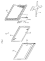
FIG. 1 is an exploded perspective view showing a schematic configuration of a television receiver according to one embodiment of the present invention; -
Fig. 2 is an exploded perspective view showing a schematic configuration of a liquid crystal display device included in the television receiver ofFig. 1 ; -
Fig. 3 is a cross-sectional view showing a sectional configuration of the liquid crystal display device ofFig. 2 , taken along a direction parallel to the short sides thereof; -
Fig. 4 is a cross-sectional view showing a sectional configuration of the liquid crystal display device ofFig. 2 , taken along a direction parallel to the long sides thereof; -
FIG. 5 is an enlarged view showing a larger view of the vicinity of an end-wall section of a hot cathode tube; -
FIG. 6 is a schematic view showing an aspect in which the hot cathode tube is being attached to a chassis; -
FIG. 7 is a schematic view showing an aspect in which the hot cathode tube has been attached to the chassis; -
FIG. 8 is an enlarged view showing a larger view of the vicinity of an end-wall section of a hot cathode tube in a comparative example; -
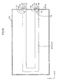
Fig. 9 is a schematic view showing the configuration of a backlight unit according to a second embodiment; -
Fig. 10 is a schematic view showing an aspect in which a glass tube of a hot cathode tube has a U shape with corners in straight angle; -
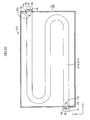
Fig. 11 is a schematic view showing the configuration of a backlight unit according to a third embodiment; -
FIG. 12 is a schematic view showing an aspect in which a glass tube of a hot cathode tube has a sigmoid shape; -
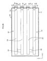
Fig. 13 is a schematic view showing the configuration of a backlight unit according to a fourth embodiment; -
Fig. 14 is a schematic view showing the configuration of a backlight unit according to a fifth embodiment; -
Fig. 15 is a schematic view showing the configuration of a backlight unit according to a sixth embodiment; -
Fig. 16 is a schematic view showing the configuration of a backlight unit according to a seventh embodiment; -
Fig. 17 is a schematic view showing the configuration of a liquid crystal display device according to an eighth embodiment; -
Fig. 18 is a schematic view showing the configuration of a liquid crystal display device according to a ninth embodiment; -
Fig. 19 is a schematic view showing the configuration of a liquid crystal display device according to a tenth embodiment; -
Fig. 20 is a schematic view showing the configuration of a liquid crystal display device according to an eleventh embodiment; -
Fig. 21 is a schematic view showing the configuration of a liquid crystal display device according to a twelfth embodiment; -
Fig. 22 is a schematic view showing the configuration of a liquid crystal display device according to a thirteenth embodiment; -
Fig. 23 is a schematic view showing the configuration of a backlight unit according to a fourteenth embodiment; -
Fig. 24 is a schematic view showing the configuration of a backlight unit according to a fifteenth embodiment; -
Fig. 25 is a schematic view showing the configuration of a backlight unit according to a sixteenth embodiment; -
Fig. 26 is a schematic view showing the configuration of a backlight unit according to a seventeenth embodiment; and -
Fig. 27 is a schematic view showing the configuration of a backlight unit according to an eighteenth embodiment. - A first embodiment of the present invention is described with reference to
Figs. 1 to 8 . Firstly, the configuration of a television receiver TV including a liquidcrystal display device 10 is described.Fig. 1 is an exploded perspective view showing a schematic configuration of the television receiver TV according to this embodiment;Fig. 2 is an exploded perspective view showing a schematic configuration of the liquid crystal display device included in the television receiver ofFig. 1 ;Fig. 3 is a cross-sectional view showing a sectional configuration of the liquid crystal display device ofFig. 2 , taken along a direction parallel to the short sides thereof; andFig. 4 is a cross-sectional view showing a sectional configuration of the liquid crystal display device ofFig. 2 , taken along a direction parallel to the long sides thereof. Note that this description assumes that the X-axis direction represents a direction parallel to the long sides of the chassis, and that the Y-axis direction represents a direction parallel to the short sides of the chassis. - As shown in
Fig. 1 , the television receiver TV according to this embodiment is configured by including the liquidcrystal display device 10, a power source P, a tuner T and a stand S. The liquid crystal display device 10 (a display device) as a whole has a horizontally-long quadrangular shape (a rectangular shape), and is housed in a stand-up state. As shown inFig. 2 , this liquidcrystal display device 10 includes a backlight unit 12 (a lighting device), which is an external light source, and a liquid crystal panel 11 (a display panel). The liquidcrystal display device 10 is configured such that these components are integrally supported via a frame-like bezel 13 and the like. Theliquid crystal panel 11 provides display by using light from thebacklight unit 12. Additionally, the liquidcrystal display device 10 is provided with two front and back cabinets Ca and Cb (housing members) configured to house both of theliquid crystal panel 11 and thebacklight unit 12 by sandwiching these components from the front and the back. The cabinet Ca (a frame-like section) has an opening Ca1 through which to expose adisplay surface 11A of theliquid crystal panel 11. In other words, the cabinet Ca surrounds the opening Ca1. - Next, the
liquid crystal panel 11 and thebacklight unit 12, which constitute the liquidcrystal display device 10, are described. The liquid crystal panel 11 (a display panel) has a configuration obtained by joining together a pair of glass substrates with a predetermined gap therebetween and enclosing liquid crystal between the two glass substrates. Provided on one of the glass substrates are switching components (e.g. , TFTs) each connected to a source line and a gate line that intersect at right angles, pixel electrodes connected to the switching components, an alignment film, and the like. Provided on the other glass substrate are a color filter, on which color sections each being of R (red), G (green), B (blue) or the like are arranged in a predetermined array, a counter electrode, an alignment film, and the like. Note that, as shown inFIG. 3 ,polarizing plates - As shown in
Fig. 2 , thebacklight unit 12 includes: achassis 14, which has anopening 14b in one side thereof having a light exiting surface (one side thereof facing the liquid crystal panel 11) and has a substantially boxlike shape; a group of optical members 15 (adiffuser plate 30, and a plurality ofoptical sheets 31 arranged between thediffuser plate 30 and the liquid crystal panel 11) arranged in a manner covering theopening 14b of thechassis 14; and frames 16 each arranged along a corresponding one of the long sides of thechassis 14, and supporting a long-side edge section of thediffuser plate 30 with the long-side edge section sandwiched between thechassis 14 and theframe 16. - In the inside of the
chassis 14, a hot cathode tube 17 (a discharge tube), which is a light source, andholders 19, which cover end sections of thehot cathode tube 17, are housed. As shown inFIGS. 3 and4 , in the central part of the inside of thechassis 14 in a direction parallel to the short sides thereof, thehot cathode tube 17 is arranged, as only one hot cathode tube, with the length direction (the axial direction) thereof agreeing with a direction parallel to the long sides of thechassis 14. While thehot cathode tube 17 is attached to thechassis 14 viaheat dissipation members 50, opposite ends (parts offerrules 17b) of thehot cathode tube 17 project and are exposed to the outside of thechassis 14 as shown inFIG. 4 . This configuration is described in detail below. Further, in the inside of thechassis 14, support pins 20 to support theoptical members 15 from the back side (one side facing the hot cathode tube 17) thereof are provided. Note that, in thebacklight unit 12, one side from thehot cathode tube 17 that faces theoptical members 15 is the light exiting side. - The
chassis 14 is made of metal. As shown inFigs. 3 and4 , thechassis 14 is composed of: abottom panel 14a having a rectangular shape in a plan view; and folded outermarginal sections bottom panel 14a. Sheet-metal forming process is used in forming thechassis 14 into a shallow, substantially boxlike shape opening toward the front (in one side facing the light exiting face) . Each of the folded outermarginal sections 21a is folded inward and extends in the direction parallel to the short sides. Each of the folded outermarginal sections 21b is folded substantially into a U shape and extends in the direction parallel to the long sides. As shown inFig. 3 , fixingholes 14c are formed in the upper surfaces of the folded outermarginal sections 21b by drilling, which makes it possible to integrate thebezel 13, theframes 16, thechassis 14 and the like by means of, for example, screws or the like. - Each of the
holders 19 covering the end sections of thehot cathode tube 17 is made of synthetic resin, the appearance of which is white, and, as shown inFig. 2 , has a long and narrow, substantially boxlike shape extending in the direction parallel to the short sides of thechassis 14. As shown inFig. 4 , while each of theholders 19 has, on the front face, a stepped surface by which theoptical members 15 or theliquid crystal panel 11 may be placed on different steps, theholders 19 are arranged in a state partially overlapping with the folded outermarginal sections 21a extending in the direction parallel to the short sides of thechassis 14. Theholders 19 thereby constitute, together with the folded outermarginal sections 21a, sidewalls of thebacklight unit 12. Insertion pins 24 are provided on and project from surfaces of theholders 19 that face the folded outermarginal sections 21a of thechassis 14, which provides a configuration where theholders 19 are attached to thechassis 14 with the insertion pins 24 inserted into insertion holes 25 formed on the upper surfaces of the folded outermarginal sections 21a of thechassis 14. - A
reflection sheet 23 is arranged on an internal surface (on a surface facing the hot cathode tube 17) of thebottom panel 14a of thechassis 14. Thereflection sheet 23 is made of synthetic resin, assumes a white color having excellent light reflectance, and is laid down along the internal surface of thebottom panel 14a of thechassis 14 in a manner almost entirely covering the internal surface. As shown inFig. 3 , the long-side edges of thereflection sheet 23 stand up in a manner covering the folded outermarginal sections 21b of thechassis 14 and are set in a state sandwiched between thechassis 14 and theoptical members 15. Thisreflection sheet 23 enables light emitted from thehot cathode tube 17 to be reflected toward theoptical members 15. - As shown in
Fig. 4 , theoptical members 15 have a rectangular shape in a plan view similarly to theliquid crystal panel 11 and thechassis 14. Theoptical members 15 is interposed between theliquid crystal panel 11 and thehot cathode tube 17, and are composed of: thediffusion plate 30 placed in the back side (one side facing thehot cathode tube 17; opposite to the light exiting side) of theoptical members 15; andoptical sheets 31 arranged in the front side (one side facing theliquid crystal panel 11; the light emitting side) thereof. Thediffusion plate 30 has a configuration obtained by dispersing a large number of diffusing particles in a substantially transparent base substrate having a predetermined thickness and made of resin. Thediffusion plate 30 has the capability to diffuse light that transmits therethrough, and has a light reflecting capability to reflect light that is emitted from thehot cathode tube 17. Theoptical sheet 31 has a sheet-like shape having a thickness thinner than that of thediffusion plate 30, and is formed by laminating, in order from thediffusion plate 30, a diffusion sheet, a lens sheet and a reflection type polarizing sheet. - The support pins 20 are configured to support the
diffusion plate 30 from the back side, and are made of synthetic resin (for example, made of polycarbonate). The overall appearances of the support pins 20 have a whitish color, such as white, which has excellent light reflectance. As shown inFigs. 2 to 4 , each of these support pins 20 is composed of: amain body section 20a forming a plate-like shape following thebottom panel 14a of thechassis 14; asupport section 20b projecting frontward (toward the optical member 15) from themain body section 20a; and anengagement section 20c projecting backward (toward thebottom panel 14a of the chassis 14) from themain body section 20a. - The engaging
section 20c includes a pair of elastic engagement pieces, and carries the function of holding thesupport pin 20 with respect to thechassis 14 by being engaged with a hole edge on the back side of anattachment hole 14d after both of the elastic engagement pieces have been inserted through theattachment hole 14d provided in thechassis 14. Thesupport section 20b as a whole has a conical shape, and is set to a length that allows the rounded apex thereof to abut on (or come close to) a surface on the back side of thediffusion plate 30. Thesupport members 20b are thereby enabled to support thediffusion plate 30 from the back side, and minimize bending of thediffusion plate 30 when thediffusion plate 30 bends. - The
diffusion plate 30 is formed by dispersedly blending a predetermined amount of diffusing particles that diffuse light into a substantially transparent base substrate made of synthetic resin (for example, made of polystyrene). Thus, the light transmittance and the light reflectance of thediffusion plate 30 as a whole are made substantially uniform. Note that it is preferable to set specific values of the light transmittance and the light reflectance of the base substrate (excluding alight reflecting section 32 to be described later) of thediffusion plate 30 to around 70% and around 30%, respectively. Thediffusion plate 30 has a surface (hereinafter referred to as afirst surface 30a) facing thehot cathode tube 17, and another surface (hereinafter referred to as asecond surface 30b) located on the side opposite to the side having thefirst surface 30a and facing theliquid crystal panel 11. This description assumes that, out of these surfaces, thefirst surface 30a is a light entering surface to which the light from thehot cathode tube 17 enters, whereas thesecond surface 30b is a light exiting surface from which light exits toward theliquid crystal panel 11. - Further, the
light reflecting section 32, which forms a dotted pattern assuming a white color, is formed on thefirst surface 30a constituting the light-entering surface in thediffusion plate 30. Thelight reflecting section 32 is formed, for example, by arranging a plurality ofdots 32a in a zigzag manner (in a zigzag alignment; in a staggered manner), the plurality ofdots 32a each having a circular shape in a plan view. The dot pattern constituting thelight reflecting section 32 is formed, for example, by being printed on the surface of thediffusion plate 30 with paste containing a metal oxide. Screen printing, ink-jet printing and the like are suitable as means for the printing. - The
light reflecting section 32 itself is configured, for example, to have light reflectance of about 75% which is higher than the light reflectance of the in-plane light reflectance of thediffusion plate 30 itself, which is set to about 30%. Here, this embodiment uses, as the light reflectance of each material, the average of light reflectance values within a measurement diameter, which are obtained by use of a LAV (with a measurement diameter ϕ at 25.4 mm) of CM-3700d manufactured by Konica Minolta Corporation. Note that a value for the light reflectance of thelight reflecting section 32 itself is set to one obtained by forming thelight reflecting section 32 all over one surface of the glass substrate and measuring, based on the above measurement means, the one surface having thelight reflecting section 32 formed thereon. - The
diffusion plate 30 is configured such that, with the dot pattern (the areas of therespective dots 32a) of thelight reflecting section 32 being varied, the light reflectance of thefirst surface 30a facing thehot cathode tube 17 of thediffusion plate 30 is varied along the direction (the Y-axis direction) parallel to the short sides. That is, thediffusion plate 30 is configured such that, in thefirst surface 30a, the light reflectance of a part (hereinafter referred to as a light source overlapping section DA) overlapping with thehot cathode tube 17 is higher than the light reflectance of a part (hereinafter referred to as a light source non-overlapping section DN) not overlapping with thehot cathode tube 17. Note that the light reflectance of thefirst surface 30a of thediffusion plate 30 is made almost invariable and substantially uniform along the direction parallel to the long sides. For the purpose of obtaining the above described distribution in light reflectance, the areas of therespective dots 32a constituting thelight reflecting section 32 are determined so that: the areas of thedots 32a in the central part, i.e., a part facing thehot cathode tube 17, of thediffusion plate 30 in a direction parallel to the short sides thereof can be the greatest; the areas of thedots 32a can gradually decrease according to how far therespective dots 32a are from the central part; and the areas of thedots 32a in the most marginal part of thediffusion plate 30 in the direction parallel to the short sides thereof can be the smallest. In other words, the areas of thedots 32a are determined so as to gradually decrease according to how far therespective dots 32a are from thehot cathode tube 17. - The
diffusion plate 30 having the above described configuration enables light emitted from thehot cathode tube 17 to: directly enter thefirst surface 30a of thediffusion plate 30, or indirectly enter thefirst surface 30a after being reflected by thereflection sheet 23, theholder 19, thesupport pin 20 and the like; then transmit through thediffusion plate 30; and, thereafter, exit toward theliquid crystal panel 11 through theoptical sheets 31. Light directly entering from thehot cathode tube 17 accounts for a large portion of light in the light source overlapping section DA which overlaps with thehot cathode tube 17 in thefirst surface 30a of thediffusion plate 30 through which light emitted from thehot cathode tube 17 enter, whereby the quantity of light in the light source overlapping section DA is relatively great as compared to that in the light source non-overlapping section DN. Therefore, relatively raising the light reflectance of thelight reflecting section 32 in the light source overlapping section DA results in reduction in light that enters thefirst surface 30a, whereby a large quantity of light is reflected and returned into the inside of thechassis 14. - On the other hand, in the
first surface 30a, the light source non-overlapping section DN not overlapping with thehot cathode tube 17 receives a little quantity of light directly from thehot cathode tube 17, and the quantity of light therein is relatively smaller than that in the light source overlapping section DA. Therefore, relatively lowering the light reflectance of thelight reflecting section 32 in the light source non-overlapping section DN makes it possible to promote entrance of light into thefirst surface 30a. At this time, light reflected into the inside of thechassis 14 by thelight reflecting section 32 of the light source overlapping section DA is guided to the light source non-overlapping section DN by thereflection sheet 23 and the like (a ray L1 ofFig. 3 ), which supplements the quantity of light therein. This makes it possible to secure a sufficient quantity of light that enters the light source non-overlapping section DN. - As mentioned above, changing the reflectance of the
diffusion plate 30 in the direction parallel to the short sides makes it possible both to obtain a configuration having thehot cathode tube 17 arranged only in the central part in the direction parallel to the short sides and to smoothen the distribution in brightness of illuminating light from thediffusion plate 30 as a whole, and thus makes it possible to achieve a smooth distribution in illumination brightness of thebacklight unit 12 as a whole. Note that, as means to condition the light reflectance, another method may be used in which, while the areas of therespective dots 32a of thelight reflecting section 32 are set equal to each other, intervals between thedots 32a are varied. - Next, the configuration of the
hot cathode tube 17 and a structure for attachment of thehot cathode tube 17 to thechassis 14 are described. As shown inFIGS. 3 and4 , thehot cathode tube 17 as a whole has a tubular shape (a linear shape), and includes ahollow glass tube 17a (a tube section), the pair offerrules 17b arranged on both end sections of theglass tube 17a, andfilaments 17d (electrodes) arranged on both ends of the inside of theglass tube 17a in the axial direction thereof. Note that, in general, the outer diameter size of the hot cathode tube 17 (theglass tube 17a) is large as compared to the outer diameter size (for example, about 4 mm) of the cold cathode tube, and is set to, for example, about 15.5 mm. - While the
glass tube 17a has a substantially cylindrical shape, a fluorescence material is applied to the inner wall surface of theglass tube 17a. Each of end-wall sections 60 on both ends in the axial direction of theglass tube 17a is composed of: aferrule attachment section 61 configured to enable either of theferrules 17b to fit in therewith from outside; and acoupling section 63 configured to couple the rim of theferrule attachment section 61 and asidewall 62 of theglass tube 17a together. Theferrule attachment section 61 is substantially U-shaped in a sectional view (illustrated by use of a dotted line inFIG. 5 ), and has a circular shape when viewed from the axial direction. The diameter of theferrule attachment section 61 is slightly smaller than the diameter of theglass tube 17a. On the other hand, thecoupling section 63 has a substantially annular shape when viewed from the axial direction. - The
ferrule attachment section 61 has anexhaust pipe 64 formed integrally therewith in a diametrically central portion thereof. Theexhaust pipe 64 is provided for the purpose of exhausting air from the inside of theglass tube 17a in manufacturing theglass tube 17a. Theexhaust pipe 64 is formed by projecting a part (a part of the end-wall section 60) of theferrule attachment section 61 so as to be far away from thefilament 17d. In other words, theexhaust pipe 64 projects from one end of theglass tube 17a. Additionally, theexhaust pipe 64 is coaxial with theglass tube 17a and the diameter of theexhaust pipe 64 is set smaller than the diameter of theferrule attachment section 61. - Here, the
exhaust pipe 64 will be explained in detail. In manufacturing theglass tube 17a, a vacuum pump (not illustrated), for example, is attached to one end (the outer side) of theexhaust pipe 64, and the vacuum pump is then driven. Air contained inside theglass tube 17a is thereby exhausted through theexhaust pipe 64. After the inside of theglass tube 17a is thus brought into a vacuum state, the inside of theglass tube 17a is filled up with mercury, rare gas and the like through theexhaust pipe 64. Thereafter, one end of theexhaust pipe 64 is fused by a burner or the like to be sealed up (a sealed section is denoted by a reference sign 65) . That is, a projecting portion is formed by sealing up one end of theexhaust pipe 64, and the sealedsection 65 is formed as a projecting end of the projecting portion. A state where mercury and rare gas are enclosed inside theglass tube 17a is reached through the above procedure. - While two
lead wires 17e penetrate, and are thereby attached to, each of theferrule attachment sections 61 of theglass tube 17a, thefilament 17d is provided as a bridge between these twolead wires 17e. Thefilament 17d is electrically connected to theferrule 17b via both of thelead wires 17e. Theferrule 17b is configured to have the same diameter as theglass tube 17a, and is attached to theglass tube 17a in a manner covering theexhaust pipe 64. Theexhaust pipe 64 is thereby protected by theferrule 17b. - The
filament 17d is arranged in a diametrically central portion of theglass tube 17a, and theexhaust pipe 64 and thefilament 17d are arranged side by side along the X-axis direction. In addition, as shown inFIG. 5 , when N1 and N2 represent the linear distance from thefilament 17d to the sealed section 65 (the projecting end of the projecting portion) and the greatest linear distance from thefilament 17d to the end-wall section 60, respectively, N1 and N2 are determined such that N1 is greater than N2. - Note that the greatest linear distance N2 from the
filament 17d to the end-wall section 60 represents a distance that is the greatest of all the linear distances between thefilament 17d and the end-wall section 60 (theferrule attachment section 61 and the coupling section 63) . In this embodiment, the linear distance from a point E1 on thefilament 17d to a diametrical end section (a point F1) of the end-wall section 60 corresponds to the greatest linear distance N2. Further, the point E1 on thefilament 17d is, for example, a position on thefilament 17d that is the nearest from the sealedsection 65. Note that the point E1 on thefilament 17d may be set to any position that is on thefilament 17d. As a result of the above configuration, the sealedsection 65 is located at a position that is the farthest of all the positions on the end-wall section 60 and the exhaust pipe 64 (more precisely, the inner surface of the end-wall section 60 and the inner surface of the exhaust pipe 64) from thefilament 17d. - As shown in
Fig. 4 , acutout 40 is formed in each of sidewalls 22 (a wall section of the chassis) that constitute the folded outermarginal sections 21a on both sides of thechassis 14 in the longitudinal direction (the X-axis direction) thereof. As shown inFig. 7 , thecutout 40 has a groove-like shape obtained by cutting out a marginal section of thesidewall 22 from the front side (the side facing the light exiting surface, or the upper side inFig. 7 ), and penetrates thesidewall 22 in the direction parallel to the long sides. Thehot cathode tube 17 is configured to be attachable to thecutouts 40 via the respectiveheat dissipation members 50 with thecutouts 40 penetrated by thehot cathode tube 17. That is, thecutouts 40 are provided as tube attachment sections. Parts of both of theferrules 17b of thehot cathode tube 17 project and are exposed to the outside of thechassis 14 through thecutouts 40. This results in the above described configuration where the sealedsections 65 of theexhaust pipes 64 are arranged outside thechassis 14. Note that, as shown inFIG. 4 , both of theferrules 17b and the sealedsections 65 are protected by being housed inside the two front and back cabinets Ca and Cb (arranged toward the inner side of the housing members) . - Each of the
heat dissipation members 50 is configured to enable heat dissipation from thehot cathode tube 17 toward thechassis 14 by being arranged between a corresponding one of thecutouts 40 and thehot cathode tube 17. Theheat dissipation member 50 is made of, for example, silicone rubber, and provides high insulation property. As shown inFIG. 7 , theheat dissipation member 50 has an annular shape having atube insertion hole 51 formed inside, and is elastically deformable in the diametrical direction thereof. The inner diameter of thetube insertion hole 51 is set substantially equal to or slightly smaller than the outer diameter of theglass tube 17a, and theglass tube 17a can be inserted through thetube insertion hole 51 in the axial direction of theglass tube 17a. As shown inFIG. 5 , this embodiment has a configuration where, with theglass tube 17a inserted through this tube insertion holes 51, the inner circumferential surface of each of theheat dissipation members 50 is in contact with both of the outer circumferential surface of theglass tube 17a and the outer circumferential surface of a corresponding one of theferrules 17b. - Note that, in the above configuration, when the
glass tube 17a is inserted into thetube insertion hole 51 in a case where the inner diameter of thetube insertion hole 51 is set slightly smaller than the outer diameter of theglass tube 17a, thetube insertion hole 51 elastically deforms in a direction such that the diameter thereof is enlarged. This makes it possible to further tighten contact between the outer circumferential surface of theglass tube 17a and the inner circumferential surface of theheat dissipation member 50, and to further facilitate heat dissipation from theglass tube 17a to theheat dissipation member 50. - The outer diameter A2 of the
heat dissipation member 50 is set greater than a width A1 of thecutout 40 in the Y-axis direction, and afitting groove 52 extending all over the circumference of theheat dissipation member 50 is concavely provided on the outward surface (the circumferential surface) thereof in the diametrical direction thereof. A groove width of thefitting groove 52 is set slightly smaller than (or substantially equal to) the thickness of thesidewall 22, and thefitting groove 52 is enabled to fit in with anedge 41 of thecutout 40. Both of theferrules 17b project to and are exposed to the outside of thechassis 14, and theheat dissipation members 50 are in contact with both of the chassis 14 (more specifically, theedge 41 of the cutouts 40) and the hot cathode tube 17 (theglass tube 17a). -
Sockets 18 are attached to therespective ferrules 17b of thehot cathode tube 17, and thefilaments 17d are electrically connected via thesockets 18 to an inverter board 26 (a power source) attached to the outward surface (the back side) of thebottom panel 14a of thechassis 14. That is, each of theferrules 17b electrically connects a corresponding one of thefilaments 17d and theinverter board 26 to each other. Driving power is supplied to thehot cathode tube 17 from theinverter board 26 and theinverter board 26 controls a tube current value, namely, brightness (the lighting state). - Next, a procedure for attachment of the
hot cathode tube 17 to thechassis 14 is described. First of all, the respectiveheat dissipation members 50 are attached to both ends of thehot cathode tube 17. Specifically, thehot cathode tube 17 is inserted into the tube insertion holes 51 of the respectiveheat dissipation members 50, whereby each of theheat dissipation members 50 is attached to a position, on the outer circumferential surface of theglass tube 17a, between corresponding ones of thefilaments 17d and theferrules 17b. Consequently, the outer circumferential surface of thehot cathode tube 17 and the inner circumferential surface of each of theheat dissipation members 50 are in contact with each other. Then, as shown inFIG. 6 , the respectiveheat dissipation members 50 are inserted from the front side (the open side of the chassis 14) into the correspondingcutouts 40, and thefitting grooves 52 of the respectiveheat dissipation members 50 are fit in with theedges 41 of thecutouts 40. Consequently, theglass tube 17a is attached to both of thecutouts 40 via both of theheat dissipation members 50, as shown inFIG. 4 . - Next, the operation and effect obtained when the
hot cathode tube 17 is lit on in thebacklight unit 12 of this embodiment are described. First of all, when driving power is supplied from theinverter board 26 to thehot cathode tube 17, electricity is discharged from thefilaments 17d of thehot cathode tube 17. Consequently, inside theglass tube 17a, electrons collide with mercury enclosed therein, and, as a result, mercury is activated, whereby ultraviolet rays are radiated. These ultraviolet rays activate the fluorescence material applied to the inner wall surface of theglass tube 17a, whereby visible light is emitted. - As mentioned above, if the
hot cathode tube 17 is lit on, temperatures inside and around theglass tube 17a rise due to heat generation (particularly, heat generation from thefilaments 17d) at the time of current passage. In this embodiment, the sealedsection 65 of theexhaust pipe 64 formed in theglass tube 17a is arranged outside thechassis 14. Therefore, this embodiment facilitates heat dissipation from the sealedsection 65 more effectively as compared to a configuration having the sealedsection 65 arranged inside thechassis 14 that tends to retain heat therein. As a result, a temperature of the sealedsection 65 is less likely to rise. - Further, the sealed
section 65 of theexhaust pipe 64 is located such that a distance between the sealedsection 65 and thefilament 17d that is a light source is longer than a distance between every portion of the end-wall section 60 and thefilament 17d. Therefore, when thefilament 17d produces heat while thehot cathode tube 17 is lit on, heat is least likely to be transferred to the sealedsection 65 among every portion of the end-wall section 60 and theexhaust pipe 64. Based on the above, the sealed section 65 (more precisely, the inner surface of the sealed section 65) of theexhaust pipe 64 is found as the coldest spot (that has the lowest temperature in theglass tube 17a; a point G1), and a temperature of the coldest spot is less likely to rise. - The temperature of the coldest spot influences a vapor pressure of mercury enclosed in the
glass tube 17a, and, by extension, influences the brightness of thehot cathode tube 17. Specifically, as the vapor pressure of mercury rises as the temperature of the coldest spot rises, the amount of ultraviolet rays released from the mercury increases, and the light emission efficiency thereby increases. As the vapor pressure of the mercury rises as the temperature of the coldest spot further rises, the amount of ultraviolet rays released by mercury and then reabsorbed by mercury around the foregoing mercury increases. Then, the amount of ultraviolet rays that hit the fluorescence material decreases, and this decrease impairs the light emission efficiency and decreases the brightness. That is, thehot cathode tube 17 has a characteristic such that, while the brightness thereof is the highest when the temperature of the coldest spot is a certain temperature (appropriate temperature), the brightness decreases as the temperature of the coldest spot becomes either higher or lower than this appropriate temperature. According to this embodiment, prevention of heating up of the coldest spot inside theglass tube 17a makes it possible to prevent the coldest spot from being brought above the appropriate temperature and also to prevent resulting decrease in brightness. - In this embodiment, the sealed
sections 65 of theexhaust pipes 64 are found as the coldest spots, as described above. That is, only the sealedsections 65 are provided outside thechassis 14 and this prevents a temperature of the coldest spot from rising. It is thereby possible to, as compared to a configuration where the coldest spots occur at any other portions inside theglass tube 17a, reduce a projecting amount by which theglass tube 17a projects outside of thechassis 14. This issue is described in detail next with reference to a comparative example shown inFIG. 8 . - In the
glass tube 17a shown in the comparative example inFIG. 8 , a length by which anexhaust pipe 164 projects is set shorter than a length by which theexhaust pipe 64 of this embodiment projects. Further, a linear distance N4 (a distance from a point E2 on thefilament 17d to a diametrical end section F2 of the end-wall section 60) is greater than a linear distance N3 (a distance from the point E2 on thefilament 17d to a sealed section G2 (a projecting end) of the exhaust pipe 164) . Therefore, a position on the end-wall section 60 and theexhaust pipe 64 of theglass tube 17a that is the farthest from thefilament 17d is found on the diametrical end section (the point F2) of the end-wall section 60. Therefore, with the configuration shown inFIG. 8 , there may be a case where the coldest spot occurs at the point F2. In a case where the coldest spot occurs at the point F2, the point F2 is necessarily provided outside thechassis 14 to prevent a temperature of the coldest spot from rising. Further, with a configuration where the point F2 is arranged outside thechassis 14, a longer portion of the end section of theglass tube 17a is required to project to the outside of thechassis 14 compared to a case with the configuration of this embodiment. - In this respect, this embodiment only requires that only the sealed
section 65 be arranged outside thechassis 14. Based on the above, this embodiment makes it possible to prevent decrease in brightness of thehot cathode tube 17 that is attributable to heating up of the coldest spots. Not only that, by setting the coldest spot at the projecting end (the sealed section 65) of theexhaust pipe 64, this embodiment makes it possible to reduce a projecting amount by which theglass tube 17a projects to outside of thechassis 14, and to reduce the width (the longitudinal width in this embodiment) of thebacklight unit 12. - Further, the
glass tube 17a includes theexhaust pipe 64 projecting from one end of theglass tube 17a. Theexhaust pipe 64 exhausts air from theglass tube 17a in manufacturing thehot cathode tubes 17. Theexhaust pipe 64 is formed as a projecting portion by sealing up an end section of theexhaust pipe 64. In a case where theexhaust pipe 64 inevitably formed in the manufacturing process of theglass tube 17a is utilized as a projecting portion, another new projecting portion is not necessarily formed and this reduces the manufacturing cost . - Further, the
inverter board 26 is provided to supply driving power to thehot cathode tube 17. Thehot cathode tube 17 has theferrules 17b each having the function of electrically connecting a corresponding one of thefilaments 17d and theinverter board 26, and theferrules 17b are attached to theglass tube 17a so as to cover the sealedsections 65. This configuration enables heat dissipation from the sealedsections 65 to theferrules 17b, and makes it possible to prevent a temperature of the sealed sections 65 (the coldest spots) from rising during lighting of thehot cathode tube 17. - Further, the
chassis 14 has thecutouts 40 penetrating thesidewalls 22 of thechassis 14, and thecutouts 40 are provided as tube attachment sections to which theglass tube 17a is attached with theglass tube 17a penetrating through thecutouts 40. The attachment of theglass tube 17a to thecutouts 40 enables the sealedsections 65 of theexhaust pipes 64 to be provided outside thechassis 14. - Further, the heat dissipation member 50is provided between each of the
cutouts 40 and theglass tube 17a. Theheat dissipation member 50 dissipates heat from theglass tube 17a to thechassis 14. With this configuration, heat that is produced while thehot cathode tube 17 is lit on is dissipated to thechassis 14 via theheat dissipation members 50. This prevents a temperature of the sealed sections 65 (the coldest spots) in theexhaust pipes 64 from rising. - Further, the
hot cathode tube 17 is used as a discharge tube. This achieves improved brightness. - A second embodiment of the present invention is described with reference to
Fig. 9 . In abacklight unit 312 of this embodiment, the shape of a hot cathode tube is different from those of the above respective embodiments. Parts identical to those of the above embodiments are denoted by the same reference signs, and redundant description is not repeated here. Thehot cathode tube 317 in this embodiment is a U-shaped tube. That is, theglass tube 317a (a tube section) is U-shaped in a plan view (in a view from the front side of the chassis 14). - The
sidewall 22 on one side (the right side ofFIG. 9 ) of thechassis 14, out of thesidewalls 22 on both sides in the X-axis direction thereof, has thecutouts 40 formed in a manner corresponding to both ends of thehot cathode tube 317. Each of the end sections of theglass tube 317a is attached to a corresponding one of thecutouts 40 with theelastic member 50 therebetween. Both of the sealedsections 65 of both of theexhaust pipes 64 are thereby arranged outside thechassis 14 by projecting to the outside thereof. The operation and effect obtained by arranging the sealedsections 65 outside thechassis 14 are similar to those in the first embodiment described above, and description thereof is not repeated here. Note that, as shown inFig. 10 , the shape of theglass tube 317a may have a U shape with corners in straight angle. With thehot cathode tube 317 being U-shaped (or U-shaped with corners in straight angle), it is possible to set, only on one end of thechassis 14, positions at which theglass tube 317a is attached to thechassis 14, whereby workability is improved. - A third embodiment of the present invention is described with reference to
Fig. 11 . In a backlight unit 412 of this embodiment, the shape of a hot cathode tube is different from those of the above respective embodiments. Parts identical to those of the above embodiments are denoted by the same reference signs, and redundant description is not repeated here. Thehot cathode tube 417 in this embodiment is a sigmoid tube, and the shape of aglass tube 417a has a sigmoid shape (a meandering shape) in a plan view (in a view from the front side of the chassis 14). - In the
sidewall 22 on one side (e.g., the right side ofFig. 11 ) of thechassis 14, which is one of thesidewalls 22 on both sides in the X-axis direction thereof, thecutout 40 is formed corresponding to one end of thehot cathode tube 417. The end section of theglass tube 417a is attached to thecutout 40 via theelastic member 50. The sealedsection 65 of theexhaust pipe 64 of thehot cathode tube 417 is thereby arranged outside thechassis 14 by projecting to the outside thereof. The operation and effect obtained by arranging the sealedsection 65 outside thechassis 14 are similar to those in each of the above described embodiments, and description thereof is not repeated here. Note that the shape of theglass tube 417a is not limited to a sigmoid shape, and may be any shape as long as the shape is a meandering shape. Additionally, as shown inFIG. 12 , the configuration may be such that the respective sealedsections 65 at both ends of thehot cathode tube 417 are arranged outside thechassis 14 by projecting to the outside thereof. As compared to a case where theglass tube 417a has a straight shape, theglass tube 417a thus configured to have a meandering shape makes it possible to enlarge, by using only the singlehot cathode tube 417, an area (a light emitting area), within the inner surface of thechassis 14 on which thehot cathode tube 417 is arranged. - A fourth embodiment of the present invention is described with reference to
Fig. 13 . Parts identical to those of the above embodiments are denoted by the same reference signs, and redundant description is not repeated here. In thechassis 14 of abacklight unit 512 of this embodiment, the plurality of (e.g., four)hot cathode tubes 17 is arranged in parallel with each other in the Y-axis direction. The respectivehot cathode tubes 17 are arranged in parallel to one another with the axial directions thereof agreeing with the X-axis direction. In this embodiment, directions toward which the sealedsections 65 project are various among thehot cathode tubes 17. - Specifically, the first and third hot cathode tubes 17 (first discharge tubes denoted by a
reference sign 17A) downward from the top inFIG. 13 are arranged outside thechassis 14 in a manner such that the sealedsections 65 project on one end (the right side inFIG. 13 ) of thechassis 14 in the direction (the X-axis direction; the width direction) parallel to the long sides thereof. That is, in thehot cathode tubes 17A, the sealedsections 65 at the one end project from the right sidewall 22 (denoted by areference sign 22R). - On the other hand, the second and fourth hot cathode tubes 17 (denoted by a
reference sign 17B, second discharge tubes) downward from the top inFIG. 13 are arranged outside thechassis 14 in a manner such that the sealedsections 65 project on the other end (the left side inFIG. 13 ) of thechassis 14 in the direction (the X-axis direction) parallel to the long sides thereof. That is, in thehot cathode tubes 17B, the sealedsections 65 at the other end project from the left sidewall 22 (denoted by areference sign 22R). In this embodiment, thehot cathode tubes 17A and thehot cathode tubes 17B are arranged alternately in the Y-axis direction. Note that a direction along which thehot cathode tubes 17 are arranged in parallel with each other is not limited to the Y-axis direction, and thehot cathode tubes 17 may be arranged in parallel with each other, for example, in the X-axis direction. In a case where thehot cathode tubes 17 are arranged in parallel with each other in the X-axis direction, it is only required that the above mentioned width direction of thechassis 14 be changed to, for example, the direction parallel to the short sides (the Y-axis direction) of thechassis 14. - A fifth embodiment of the present invention is described with reference to
Fig. 14 . Parts identical to those of the above embodiments are denoted by the same reference signs, and redundant description is not repeated here. In thechassis 14 of abacklight unit 612 of this embodiment, the plurality of (e.g., six)hot cathode tubes 17 is arranged in parallel with each other in the Y-axis direction. The respectivehot cathode tubes 17 are arranged in parallel to one another with the axial directions thereof agreeing with the X-axis direction. Additionally, directions toward which the sealedsections 65 project are various among groups (discharge tube groups) of thehot cathode tubes 17 that are next to one another. - Specifically, when a group of the first and second
hot cathode tubes 17 downward from the top, a group of the third and the fourthhot cathode tubes 17 downward from the top, and a group of the fifth and sixthhot cathode tubes 17 downward from the top, inFIG. 14 , are defined as adischarge tube group 617D (a first discharge tube group), adischarge tube group 617E (a second discharge tube group), and adischarge tube group 617F (another first discharge tube group), respectively, the sealedsections 65 of the respective hot cathode tubes 17 (denoted byreference signs discharge tube group 617D and thedischarge tube group 617F are arranged outside thechassis 14 in a manner projecting on one end (the right side inFIG. 14 ) of thechassis 14 in the direction parallel to the long sides (the width direction) thereof. - On the other hand, the sealed
sections 65 of the respective hot cathode tubes 17 (denoted by areference sign 17E) in thedischarge tube group 617E are arranged outside thechassis 14 in a manner projecting on the other end (the left side inFIG. 14 ) of thechassis 14 in the direction parallel to the long sides (the width direction) thereof. Additionally, the first discharge tube groups and the second discharge tube group are arranged alternately in the Y-axis direction. Note that any group of two or morehot cathode tubes 17 that are next to one another is applicable as each of the above described discharge tube groups, which means that the number of thehot cathode tubes 17 constituting each of the discharge tube groups may be changed as appropriate. - A sixth embodiment of the present invention is described with reference to
Fig. 15 . Parts identical to those of the above embodiments are denoted by the same reference signs, and redundant description is not repeated here. In thechassis 14 of a backlight unit 712 of this embodiment, the plurality of (e.g., four)hot cathode tubes 17 is arranged in parallel with each other in the Y-axis direction. Thehot cathode tubes 17 are arranged in parallel to one another with the axial directions thereof agreeing with the X-axis. The sealedsections 65 of the respectivehot cathode tubes 17 are exposed to the outside of thechassis 14 in a manner projecting on one end of the chassis 14 (the right side inFIG. 15 ) in the direction parallel to the long sides (the width direction) thereof. In other words, the sealedsections 65 arranged outside thechassis 14 are unevenly distributed on one end of thechassis 14. - A seventh embodiment of the present invention will be described with reference to
Fig. 16 . Parts identical to those of the above embodiments are denoted by the same reference signs, and redundant description is not repeated here. In abacklight unit 812 of this embodiment, the plurality of (e.g., four)hot cathode tubes 17 is arranged in parallel with each other in thechassis 14. Thehot cathode tubes 17 are arranged in parallel to one another with the axial directions thereof agreeing with the X-axis. In this embodiment, only the sealedsections 65 of the hot cathode tubes 17 (denoted by areference sign 17G) that are arranged in the central part of the direction of arranging the hot cathode tubes 17 (the Y-axis direction) are arranged outside thechassis 14. In a case where the plurality ofhot cathode tubes 17 is arranged in parallel with each other, the central part in the direction along which thehot cathode tubes 17 are arranged in parallel with each other tends to have a relatively higher temperature than the other parts inside thechassis 14. Therefore, it is particularly effective to prevent heating up of the coldest spots by exposing the sealedsections 65 of only thehot cathode tubes 17G arranged in the central part. - Note that a condition where some of the
hot cathode tubes 17 are arranged in the middle portion of thechassis 14 in a direction (e.g., the Y-axis direction) along which thehot cathode tubes 17 are arranged in parallel with each other implies a condition where anotherhot cathode tubes 17 are arranged on the respective sides (the upper and lower sides inFig. 16 ) of thehot cathode tubes 17G. Additionally, the number of thehot cathode tubes 17G arranged in the middle portion may be changed as appropriate. - An eighth embodiment of the present invention is described with reference to
Fig. 17 . Parts identical to those of the above embodiments are denoted by the same reference signs, and redundant description is not repeated here. In a liquidcrystal display device 310 of this embodiment, ventilation openings 311 (a cooling mechanism) are formed in the four corners of the rectangular cabinet Cb at the back by penetrating the cabinet Cb in the frontward-backward direction. For example, a slit shape (ventilation openings 311A in the left side) and a rectangular shape (ventilation openings 311B in the right side) can be presented as examples of the shape of each of theventilation openings 311. Further, in abacklight unit 320 of this embodiment, thechassis 14 includes, for example, the twohot cathode tubes 17, and both of the sealedsections 65 of each of thehot cathode tubes 17 are arranged outside thechassis 14 by projecting to the outside thereof. - Both of the
ventilation openings 311A in the left side inFIG. 17 are aligned along the Y-axis direction, and arranged so as to line up substantially in alignment with the sealedsections 65 in the left sides that project from achassis 22. Both of theventilation openings 311B in the right side are aligned along the Y-axis direction, and arranged so as to line up substantially in alignment with the sealedsections 65 in the right side that project from thechassis 22. - According to the above configuration, when the
hot cathode tubes 17 are lit on, air inside the front and back cabinets Ca and Cb is exhausted from therespective ventilation openings 311. This prevents accumulation of heat inside the cabinets Ca and Cb. Heat dissipation from the sealedsections 65 can be thereby further facilitated. In other words, theventilation openings 311 constitute a cooling mechanism configured to enable cooling of the sealedsections 65. - Further, arranging both of the
ventilation openings 311A in alignment with the sealedsections 65 makes it more likely that airflows occur around sealedsections 65 in the insides of the cabinets Ca and Cb. Specifically, for example, air having flown into the insides of the cabinets Ca and Cb from theventilation opening 311A in the lower side is exhausted from theventilation opening 311A in the upper side after passing through areas surrounding theferrules 17b (the sealed sections 65) in the left side. This further facilitates heat dissipation from the sealedsections 65, and more effectively prevents a temperature of the coldest spots from rising. Theventilation openings 311 andferrules 17b in the right side exhibit the same operation and effect as those in the left side. Note that the number of theventilation openings 311 and a position at which to form each of theventilation openings 311 are not limited by the configuration of this embodiment, and may be changed as appropriate. Alternatively, theventilation openings 311 may be composed only of the slit-like ventilation openings 311A, or may be composed only of theventilation openings 311B having rectangular shapes. The shape of each of therespective ventilation openings 311 is not limited to one mentioned in this embodiment, and may be another shape (e.g., a circular shape). - A ninth embodiment of the present invention is described with reference to
Fig. 18 . Parts identical to those of the above embodiments are denoted by the same reference signs, and redundant description is not repeated here. In a liquidcrystal display device 410 of this embodiment, cooling fans 411 (a cooling mechanism) for cooling the sealedsections 65 are provided at two positions of the back cabinet Cb. For example, a motor (not illustrated) is connected to each of the coolingfans 411. The configuration is such that air is blown by rotation of the coolingfan 411 when the motor is driven to rotate by receiving power supply from a power source not illustrated. Each of the coolingfans 411 is provided next to one of the sealed sections 65such that air blow from the coolingfan 411 forwards the sealedsection 65. With the above configuration, each cooling fan is activated while thehot cathode tubes 17 is lit on, and the sealedsections 65 are cooled more effectively and a temperature of the sealedsections 65 is prevented from rising. - A tenth embodiment of the present invention is described with reference to
Fig. 19 . Parts identical to those of the above embodiments are denoted by the same reference signs, and redundant description is not repeated here. In a liquidcrystal display device 510 of this embodiment, cooling elements 511 (a cooling mechanism) are provided in the back cabinet Cb. For example, Peltier elements are used as therespective cooling elements 511. A power source not illustrated is connected to each of thecooling elements 511. When an electric current is conducted through thecooling element 511, one surface of thecooling elements 511 absorbs heat, and the other surface thereof produces heat. Note that each of thecooling elements 511 is not limited to a Peltier element. - In this embodiment, the
respective cooling elements 511 are installed in a manner corresponding to the sealedsections 65 projecting rightward and leftward. More specifically, the heat-absorbing surfaces of therespective cooling elements 511 are in contact with theferrules 17b, and the heat-producing surfaces thereof are in contact with the cabinet Cb. Consequently, when electric currents are conducted through thecooling elements 511, heat of the sealedsections 65 are absorbed by the cooling elements through theferrules 17b. The absorbed heat is dissipated to the cabinet Cb from the heat-producing surface. Therefore, heating up of the sealedsections 65 can be prevented. - An eleventh embodiment of the present invention is described with reference to
Fig. 20 . Parts identical to those of the above embodiments are denoted by the same reference signs, and redundant description is not repeated here. In a liquidcrystal display device 610 of this embodiment, the back cabinet Cb is provided with heat pipes 611 (a cooling mechanism). For example, each of theheat pipes 611 is configured to function as a heat transfer member having an excellent heat transferring capability, and is composed of a pipe made of copper or a copper alloy. For example, water is contained as a refrigerant in the pipe. - As shown in
FIG. 20 , therespective heat pipes 611 are installed corresponding to the sealedsections 65 projecting rightward and leftward. One end (the lower end inFig. 20 ) of each of theheat pipes 611 is in contact with theferrules 17b, and the other end (the upper end inFig. 20 ) thereof is in contact with the cabinet Cb. Consequently, when heat of the sealedsections 65 reaches theheat pipes 611 through theferrules 17b, the heat is transferred toward the cabinet Cb through the insides of theheat pipes 611 by means of latent heat involved in evaporation and condensation of water contained in theheat pipes 611. This makes it possible to more effectively prevent a temperature of the sealedsections 65 which are the coldest spots from rising. - A twelfth embodiment of the present invention is described with reference to
Fig. 21 . Parts identical to those of the above embodiments are denoted by the same reference signs, and redundant description is not repeated here. Acirculation pipe 720, water (a refrigerant) enclosed in the inside of thecirculation pipe 720, and arefrigerant circulation pump 721 are included, as cooling mechanism, in a liquidcrystal display device 710 of this embodiment. Thecirculation pipe 720 has a substantially frame-like shape, and is arranged in a manner surrounding thechassis 14. Additionally, a part of thecirculation pipe 720 is in contact with (or close to) each of theferrules 17b. Therefrigerant circulation pump 721 is connected to thecirculation pipe 720, and connected to a power source not illustrated. This provides a configuration that causes water to circulate within thecirculation pipe 720 when therefrigerant circulation pump 721 is driven. - The above configuration causes water, which is a refrigerant, to circulate through the inside of the
circulation pipe 720 when therefrigerant circulation pump 721 is driven. Heat of the sealedsections 65 is thereby absorbed by water inside thecirculation pipe 720 through theferrules 17b. The absorbed heat is dissipated, for example, to the cabinet Cb as water circulates. This makes it possible to continually cool the sealedsections 65 by causing water to circulate, whereby heating up of the sealedsections 65 can be prevented. Note that some of the cooling mechanisms given as examples in the sixteenth to twentieth embodiments described above may be used and installed inside the cabinets in combination. - A thirteenth embodiment of the present invention is described with reference to
Fig. 22 . Parts identical to those of the above embodiments are denoted by the same reference signs, and redundant description is not repeated here. In abacklight unit 912 in a liquidcrystal display device 910 of this embodiment, aglass tube 917a of ahot cathode tube 917 is L-shaped. Additionally, in this embodiment, only one end of thehot cathode tube 917 projects to the outside of the chassis. Specifically, the one end of thehot cathode tube 917 projects on the back side of thechassis 14 through a throughhole 40 formed in thebottom panel 14a of thechassis 14. The sealedsection 65 of theglass tube 917a is thereby arranged outside thechassis 14 in a manner projecting on the back side of thechassis 14. Using a configuration where the sealedsection 65 projects on the back side makes it possible to reduce the length of thebacklight unit 912 in the width direction thereof as compared to a configuration where the sealedsection 65 projects from the sidewall. - A fourteenth embodiment of the present invention is described with reference to
Fig. 23 . Parts identical to those of the above embodiments are denoted by the same reference signs, and redundant description is not repeated here. In abacklight unit 200 of this embodiment, ahot cathode tube 201 is formed by joining a plurality of glass tubes (tube sections) together. Specifically, each of the glass tubes in thehot cathode tube 201 is formed by joining glass tube main body sections (tube sections, hereinafter referred to as main body sections 202) and a glass tube joining section (a tube section, hereinafter referred to as a joining section 203) together. Each of themain body sections 202 has a tubular shape and the twomain body sections 202 are arranged in parallel to each other with the axial directions thereof matching with the longitudinal direction of thechassis 14. The joiningsection 203 has a tubular shape, and both end sections thereof are fusion-joined to the respectivemain body sections 202. Thus, both of themain body sections 202 are coupled together by means of the joiningsection 203, and the internal space of the joiningsection 203 communicates with the internal spaces of the respectivemain body sections 202. - The
ferrule 17b is mounted on one end of each of themain body sections 202. Note that a position at which the joiningsection 203 is joined to each of themain body sections 202 is set relatively close to one side (the other end), of themain body section 202, on which theferrule 17b is not mounted. Additionally, like each of the above embodiments, this embodiment uses a configuration where, while parts of theferrules 17b are exposed to the outside of thechassis 14 through thecutouts 40 formed in thechassis 14, the sealedsections 65 of theexhaust pipes 64 are arranged outside thechassis 14. The operation and effect obtained by arranging the sealedsections 65 outside thechassis 14 are the same as those in each of the above embodiments, and description thereof is not repeated here. - A fifteenth embodiment of the present invention is described with reference to
Fig. 24 . Parts identical to those of the above embodiments are denoted by the same reference signs, and redundant description is not repeated here. In abacklight unit 210 of this embodiment, a plurality of (e.g., three)hot cathode tubes 211 is arranged in parallel with each other in the Y-axis direction. Each of thehot cathode tubes 211 is configured in the same manner as thehot cathode tube 201 in the fourteenth embodiment described above. Thehot cathode tube 211 is formed by joiningmain body sections 212 and a joiningsection 213 together, and has the sealedsections 65 arranged outside thechassis 14. The respectivehot cathode tubes 211 are arranged with themain body sections 212 thereof being set parallel to one another. - In the first and third hot cathode tubes 211 (
first discharge tubes 211A) downward from the top inFIG. 24 , the sealedsections 65 are arranged outside thechassis 14 with projecting to the right side (one end) ofFIG. 24 in the direction parallel to the long sides (the X-axis direction; the width direction) of thechassis 14. - On the other hand, in the second hot cathode tube 211 (
second discharge tube 211B) downward from the top inFIG. 24 , the sealedsections 65 are arranged outside of thechassis 14 with projecting to the left side (the other end) ofFIG. 24 in the direction parallel to the long sides (the width direction) of thechassis 14. That is, in this embodiment, thehot cathode tubes 211A and thehot cathode tube 211B are arranged alternately in the Y-axis direction. - A sixteenth embodiment of the present invention is described with reference to
Fig. 25 . Parts identical to those of the above embodiments are denoted by the same reference signs, and redundant description is not repeated here. In abacklight unit 220 of this embodiment, a plurality of (e.g., six)hot cathode tubes 221 is arranged in parallel with each other in the Y-axis direction. As in the case of thehot cathode tube 201 in the fourteenth embodiment described above, each of thehot cathode tubes 221 is formed by joining togethermain body sections 222 and a joiningsection 223. A part of eachferrule 17b is exposed to the outside of thechassis 14, and the sealed sections (not illustrated) of the exhaust pipes covered by theferrules 17b are arranged outside thechassis 14. Thesehot cathode tubes 221 are arranged with the respectivemain body sections 222 thereof being set parallel to each other. - In this embodiment, the
ferrules 17b (as a result, the sealed sections) project in different directions among groups (discharge tube groups) of thehot cathode tubes 221 that are next to one another. Specifically, a group of the first and secondhot cathode tubes 221 downward from the top, a group of the third and fourthhot cathode tubes 221 downward from the top, and a group of the fifth and sixthhot cathode tubes 221 downward from the top, inFIG. 25 , are defined as adischarge tube group 224D (a first discharge tube group), adischarge tube group 224E (a second discharge tube group), and adischarge tube group 224F (another first discharge tube group), respectively. Parts of theferrules 17b in the respective hot cathode tubes 221 (221D and 221F) in thedischarge tube group 221D and thedischarge tube group 221F are exposed to the outside of thechassis 14 with projecting from one end (the left side inFIG. 25 ) of thechassis 14 in the direction parallel to the long sides (the width direction) thereof. - On the other hand, parts of the
ferrules 17b in the hot cathode tubes 221 (221E) in thedischarge tube group 224E are exposed to the outside of thechassis 14 with projecting from the other end (the right side inFIG. 25 ) of thechassis 14 in the direction parallel to the long sides (the width direction) thereof. That is, the first discharge tube groups and the second discharge tube group are arranged alternately in the Y-axis direction. Note that any group of the two or morehot cathode tubes 221 that are next to one another is applicable as each of the above described discharge tube groups, and that the number of thehot cathode tubes 221 constituting each of the discharge tube groups may be changed as appropriate. - A seventeenth embodiment of the present invention is described with reference to
Fig. 26 . Parts identical to those of the above embodiments are denoted by the same reference signs, and redundant description is not repeated here. In abacklight unit 230 of this embodiment, a plurality of (e.g. , two)hot cathode tubes 231 is arranged in parallel with each other in the Y-axis direction. As in the case of thehot cathode tube 201 in the fourteenth embodiment described above, each of thehot cathode tubes 231 has a configuration obtained by joiningmain body sections 232 and a joiningsection 233 together. Thesehot cathode tubes 231 are arranged with themain body sections 232 thereof being set parallel to one another. In the respectivehot cathode tubes 231, the sealedsections 65 of theexhaust pipes 64 are arranged outside thechassis 14 in a manner projecting on one end (the right side inFIG. 26 ) of thechassis 14 in the direction parallel to the long sides (the width direction) thereof. In other words, the sealedsections 65 that correspond to parts arranged outside thechassis 14 are unevenly distributed on one end of thechassis 14. - An eighteenth embodiment of the present invention is described with reference to
Fig. 27 . Parts identical to those of the above embodiments are denoted by the same reference signs, and redundant description is not repeated here. In abacklight unit 240 of this embodiment, apluralityof (e.g., four)hot cathode tubes 241 is arranged in parallel with each other in the Y-axis direction. As in the case of thehot cathode tube 201 in the fourteenth embodiment described above, each of thehot cathode tubes 241 has a configuration obtained by joiningmain body sections 242 and a joiningsection 243 together. - In this embodiment, the sealed
sections 65 of themain body sections 242 of the hot cathode tubes 241 (denoted by areference sign 241G) that are arranged in the middle portion of the chassis in the arrangement direction of the hot cathode tubes 241 (the Y-axis direction) are arranged outside thechassis 14. In a case where the plurality ofhot cathode tubes 241 is arranged in parallel with each other, the middle portion of thechassis 14 in the direction along which thehot cathode tubes 241 are arranged in parallel with each other tends to have a relatively high temperature. Therefore, it is particularly effective to provide outside thechassis 14 the sealedsections 65 of thehot cathode tubes 241G in the middle portion to prevent a temperature of the coldest spots from rising. - Note that a condition where the
hot cathode tubes 241 are arranged in the middle portion in a direction (e.g. , the Y-axis direction) along which thehot cathode tubes 241 are arranged in parallel with each other implies a condition where anotherhot cathode tubes 241 are arranged on either sides (the upper and lower sides inFig. 27 ) of thehot cathode tubes 241G. Additionally, the number of thehot cathode tube 241G arranged in the central part is not limited two, and may be changed as appropriate. - The present invention is not limited to the above embodiments explained in the above description and drawings. The following embodiments may be included in the technical scope of the present invention, for example.
- (1) Although each of the above embodiments uses a configuration utilizing the
exhaust pipe 64 as the projecting portion, the present invention is not limited to this. The projecting portion may be any portion obtained by causing a part of the end-wall section 60 to project to be far away from thefilament 17d, and the shape thereof may be changed as appropriate. - (2) Although each of the above embodiments uses a configuration having the sealed
section 65 of theexhaust pipe 64 covered by theferrule 17b, the present invention is not limited to this. Another configuration may be used where the sealedsection 65 is exposed to the outside thechassis 14 without being covered by theferrule 17b. - (3) The
exhaust pipe 64 may be formed only in the end-wall section 60 on one end of theglass tube 17a in the axial direction thereof. - (4) A configuration where the
hot cathode tube 17 is attached to thecutout 40 in the sidewall 22 (the wall section) of thechassis 14 is shown as an example in each of the above embodiments. However, it is not always necessary that thehot cathode tube 17 be attached to the wall section of thechassis 14. It is only required that the projecting portion (the sealedsection 65 of the exhaust pipe 64) projecting from the end-wall section 60 of thehot cathode tube 17 be exposed to the outside of thechassis 14. Therefore, a position to which thehot cathode tube 17 is attached, and means used for attaching thehot cathode tube 17 may be changed as appropriate. - (5) Each of the above embodiments uses a configuration where the
hot cathode tube 17 is attached to thechassis 14 with theheat dissipation member 50 provided therebetween. However, another configuration that does not include the heat dissipation member may be used. - (6) Each of the above embodiments uses a configuration where the
heat dissipation member 50 is set in contact with both of the outer circumferential surface of theglass tube 17a and theferrule 17b. However, another configuration may be used where theheat dissipation member 50 is set in contact with any one of the outer circumferential surface of theglass tube 17a and theferrule 17b. - (7) Although silicone rubber is used for the material of the heat dissipation member in each of the above embodiments, the present invention is not limited to this. The material of the heat dissipation member may be changed as appropriate. Note that a material having a high thermal conductivity is preferable as the material of the heat dissipation member.
- (8) Any cutout which penetrates the chassis in a manner enabling communication between the outer and inner sides thereof, and through which a discharge tube can be inserted is applicable as each of the cutouts in the above embodiments, and the shape thereof may be changed as appropriate.
- (9) In each of the above embodiments, a case where the
hot cathode tube 17 is provided in a manner extending in a direction parallel to the long sides (the x-axis direction) of thechassis 14 is shown as an example. However, thehot cathode tube 17 may be provided in a manner extending in a direction parallel to the short sides (the Y-axis direction) of thechassis 14. In a case where this configuration is used, it is only required that the configuration be such that the sealedsections 65 of thehot cathode tube 17 are projected from the sidewalls on both sides of thechassis 14 in the direction parallel to the short sides thereof. - (10) Although a configuration where the
hot cathode tubes 17 are arranged in parallel with each other along the Y-axis direction is shown as an example in each of the above described embodiments, a direction along which the hot cathode tubes are arranged in parallel with each other is not limited to the Y-axis direction, and the hot cathode tubes may be arranged in parallel with each other, for example, in the x-axis direction. - (11) Although a case using the
hot cathode tube 17 as a discharge tube is shown in each of the above described embodiments, the present invention also includes a case using a discharge tube (such as a cold cathode tube or a xenon tube, for example) of another type. - (12) Although a case using only one kind of discharge tubes is shown in each above described embodiment, the present invention includes a case using two or more kinds of discharge tube in combination. For example, a cold cathode tube and a hot cathode tube may be used in combination.
- (13) Although a case where a liquid crystal panel and a chassis are set in a stand-up state with a direction parallel to the short sides thereof agreeing with the vertical direction is given as an example in each of the above described embodiments, the present invention also includes a case where a liquid crystal panel and a chassis are set in a stand-up state with a direction parallel to the long sides thereof agreeing with the vertical direction.
- (14) Although a TFT is used as each switching component of the liquid crystal display device in each of the above described embodiments, the present invention is applicable also to liquid crystal display devices using switching components (e.g., thin-film diodes (TFDs)) other than TFTs, and to liquid crystal display devices, such as liquid crystal display devices that provide monochrome display, other than those that provide color display.
- (15) Although a liquid crystal display device using a liquid crystal panel as a display panel is shown as an example in each of the above described embodiment, the present invention is also applicable to the display device using other types of display panels.
- (16) Although a television receiver including a tuner is given as an example in each of the above described embodiments, the present invention is applicable also to a display device not including a tuner.
-
- 10, 310, 410, 510, 610, 710: Liquid crystal display device (Display device)
- 11: Liquid crystal panel (Display panel)
- 12, 200, 210, 220, 230, 240, 312, 320, 412, 512, 612, 712, 812, 912: Backlight unit (Lighting device)
- 14: Chassis
- 17, 201, 211, 221, 221D, 221E, 221F, 231, 241, 317, 417, 917: Hot cathode tube (Discharge tube)
- 17a, 317a, 417a, 917a: Glass tube (Tube section)
- 17b: Ferrule
- 17d: Filament (Electrode)
- 17A, 211A: Hot cathode tube (First discharge tube)
- 17B, 211B: Hot cathode tube (Second discharge tube)
- 17G, 241G: Hot cathode tube (Discharge tube arranged in central part of discharge tubes in direction along which discharge tubes are arranged in parallel with each other)
- 22: Sidewall (Sidewall section of chassis)
- 26: Inverter board (Power source)
- 40: Cutout (Tube attachment section)
- 50: Heat dissipation member
- 60: End-wall section
- 64: Exhaust pipe (Projecting portion)
- 65: Sealed section (Projecting end of projecting portion)
- 202, 212, 222, 232, 242: Main body section (Tube section)
- 203, 213, 223, 233, 243: Joining section (Tube section)
- 311, 311A, 311B: Ventilation opening (Cooling mechanism)
- 617D, 617F: Discharge tube group (First discharge tube group)
- 617E: Discharge tube group (Second discharge tube group)
- 411: Cooling fan (Cooling mechanism)
- 511: Cooling element (Cooling mechanism)
- 611: Heat pipe (Cooling mechanism)
- 720: Circulation pipe
- 721: Refrigerant circulation pump
- N1: Linear distance (Linear distance from electrode to projecting end of projecting portion)
- N2: greatest linear distance (Greatest linear distance from electrode to end-wall section at one end)
- TV: Television receiver
- Ca: Cabinet (Frame-like section; housing member)
- Cal : Opening
- Cb: Cabinet (Housing member)
Claims (25)
- A lighting device comprising:a discharge tube, the discharge tube including a tube section and an electrode arranged inside the tube section, the tube section having an end wall on one end in an axial direction thereof and a projecting portion projecting from the end wall so as to be away from the electrode; anda chassis housing the discharge tube, wherein:the projecting portion has a projecting end that is provided outside the chassis; anda linear distance between the electrode and the projecting end of the projecting portion is greater than a greatest linear distance between the electrode and the end wall on the one end.
- The lighting device according to claim 1, wherein:the tube section includes an exhaust pipe projecting from the one end of the tube section and configured to exhaust air from the tube section in manufacturing the discharge tube; andthe exhaust pipe is configured as the projecting portion by closing an end of the exhaust pipe.
- The lighting device according to any one of claims 1 and 2, further comprising a power source configured to supply driving power to the discharge tube, wherein:the discharge tube includes a ferrule configured to electrically connect the electrode and the power source to each other; andthe ferrule is attached to the tube section to cover the projecting portion.
- The lighting device according to any one of claims 1 to 3, wherein:the chassis has a wall section and a cutout penetrating the wall section; andthe cutout is provided as a tube attachment section to which the tube section is attached with penetrating the cutout.
- The lighting device according to claim 4, further comprising a heat dissipation member provided between an edge of the cutout and the tube section, the heat dissipation member being configured to dissipate heat from the tube section toward the chassis.
- The lighting device according to any one of claims 1 to 5, wherein:the discharge tube includes a plurality of discharge tubes arranged in parallel with each other in the chassis, and the plurality of discharge tubes includes first discharge tubes and second discharge tubes;each of the first discharge tubes has the projecting end of the projecting portion that is disposed outside the chassis and projects from one end of the chassis in a width direction of the chassis;each of the second discharge tubes has the projecting end of the projecting portion that is disposed outside the chassis and projects from another end of the chassis in a width direction of the chassis; andthe first discharge tubes and the second discharge tubes are alternately arranged in parallel with each other.
- The lighting device according to any one of claims 1 to 5, wherein:the discharge tube includes a plurality of discharge tubes and the plurality of discharge tubes is arranged in parallel with each other in the chassis;the discharge tubes include a plurality of discharge tube groups each including at least two adjacent discharge tubes;the discharge tube groups include a first discharge tube group and a second discharge tube group;the projecting end of the projecting portion of each discharge tube of the first discharge tube group is disposed outside the chassis and projects from one end of the chassis in a width direction of the chassis;the projecting end of the projecting portion of each discharge tube of the second discharge tube group is disposed outside the chassis and projects from another end of the chassis in a width direction of the chassis; andthe first discharge tube group and the second discharge tube group are alternately arranged to be parallel to each other.
- The lighting device according to any one of claims 1 to 5, wherein:the discharge tube includes a plurality of discharge tubes that is arranged in parallel with each other in the chassis; and,each projecting end of the projecting portions of the discharge tubes are provided outside the chassis so as to project from one end of the chassis in a width direction of the chassis.
- The lighting device according to any one of claims 1 to 5, wherein:the discharge tube includes a plurality of discharge tubes that is arranged in parallel with each other in the chassis; andonly the discharge tubes that are arranged in a middle portion of the chassis in an arrangement direction of the discharge tubes have projecting ends of the projecting portions that are provided outside the chassis.
- The lighting device according to any one of claims 1 to 9, wherein the discharge tube is substantially L-shaped.
- The lighting device according to any one of claims 1 to 9, wherein the discharge tube is substantially U-shaped.
- The lighting device according to any one of claims 1 to 9, wherein the discharge tube has a meandering shape.
- The lighting device according to any one of claims 1 to 12, wherein the tube section includes a plurality of tube sections and the discharge tube is formed by joining the plurality of tube sections together.
- The lighting device according to any one of claims 1 to 13, wherein the discharge tube is a hot cathode tube.
- A display device comprising:the lighting device according to any one of claims 1 to 14; anda display panel configured to provide display by using light from the lighting device.
- The display device according to claim 15, wherein the display panel is a liquid crystal panel using liquid crystal.
- The display device according to any one of claims 15 and 16, further comprising a housing member configured to house the display panel and the lighting device, wherein:the housing member includes an opening section through which a display surface of the display panel is exposed, and a frame-like section surrounding the opening section; andthe projecting end of the projecting portion is provided in the housing member.
- The display device according to claim 17, further comprising a cooling mechanism provided in the housing member and configured to cool the projecting end of the projecting portion.
- The display device according to claim 18 wherein the cooling mechanism includes a ventilation opening penetrating through the housing member.
- The display device according to any one of claims 18 and 19, wherein the cooling mechanism includes a cooling fan conf igured to send air toward the projecting end of the projecting portion and thereby cool the projecting end of the projecting portion.
- The display device according to any one of claims 18 to 20, wherein the cooling mechanism includes a cooling element configured to come in contact with the projecting end of the projecting portion and thereby cool the projecting end of the projecting portion.
- The display device according to any one of claims 18 to 21, wherein the cooling mechanism includes a heat pipe configured to transfer heat of the projecting end of the projecting portion to the housing member.
- The display device according to any one of claims 18 to 22, wherein the cooling mechanism includes:a refrigerant configured to cool the projecting end of the projecting portion;a circulation pipe in which the refrigerant is contained; anda refrigerant circulation pump connected to the circulation pipe, and configured to circulate the refrigerant within the circulation pipe.
- The display device according to claim 23, wherein the refrigerant is water.
- A television receiver comprising the display device according to any one of claims 15 to 24.
Applications Claiming Priority (2)
| Application Number | Priority Date | Filing Date | Title |
|---|---|---|---|
| JP2009213494 | 2009-09-15 | ||
| PCT/JP2010/061772 WO2011033847A1 (en) | 2009-09-15 | 2010-07-12 | Lighting device, display device, and television receiver |
Publications (2)
| Publication Number | Publication Date |
|---|---|
| EP2479476A1 true EP2479476A1 (en) | 2012-07-25 |
| EP2479476A4 EP2479476A4 (en) | 2013-01-02 |
Family
ID=43758461
Family Applications (1)
| Application Number | Title | Priority Date | Filing Date |
|---|---|---|---|
| EP10816960A Withdrawn EP2479476A4 (en) | 2009-09-15 | 2010-07-12 | Lighting device, display device, and television receiver |
Country Status (10)
| Country | Link |
|---|---|
| US (1) | US20120162577A1 (en) |
| EP (1) | EP2479476A4 (en) |
| JP (1) | JPWO2011033847A1 (en) |
| KR (1) | KR20120055690A (en) |
| CN (1) | CN102498329A (en) |
| AU (1) | AU2010296639A1 (en) |
| BR (1) | BR112012005769A2 (en) |
| RU (1) | RU2012109550A (en) |
| SG (1) | SG179110A1 (en) |
| WO (1) | WO2011033847A1 (en) |
Families Citing this family (2)
| Publication number | Priority date | Publication date | Assignee | Title |
|---|---|---|---|---|
| JP5979656B2 (en) * | 2011-07-22 | 2016-08-24 | 株式会社Spd研究所 | UV irradiation curing equipment |
| US11004645B2 (en) * | 2019-07-25 | 2021-05-11 | Disney Enterprises, Inc. | Display assembly with anti-reflective film applied to video monitor with vacuum suction |
Family Cites Families (27)
| Publication number | Priority date | Publication date | Assignee | Title |
|---|---|---|---|---|
| JPH03179485A (en) * | 1989-12-08 | 1991-08-05 | Toshiba Lighting & Technol Corp | Lighting device |
| JPH06273765A (en) * | 1993-01-19 | 1994-09-30 | Canon Inc | Back light device and liquid crystal display device using the same |
| KR100469343B1 (en) * | 2001-08-16 | 2005-02-02 | 엘지.필립스 엘시디 주식회사 | Back light |
| TW525792U (en) * | 2002-01-29 | 2003-03-21 | Chi Mei Optoelectronics Corp | Liquid crystal display device and backlight module thereof |
| KR100840718B1 (en) * | 2002-05-31 | 2008-06-23 | 삼성전자주식회사 | Back light assembly and liquid crystal display device having the same |
| KR100883091B1 (en) * | 2002-06-28 | 2009-02-11 | 삼성전자주식회사 | Mold frame, backlight assembly and liquid crystal display having the same |
| TW567292B (en) * | 2002-07-31 | 2003-12-21 | Benq Corp | Lamp module and back light device having the same |
| KR100525440B1 (en) * | 2002-12-31 | 2005-11-02 | 엘지.필립스 엘시디 주식회사 | Back light unit |
| JP2004349040A (en) * | 2003-05-21 | 2004-12-09 | Nec Lcd Technologies Ltd | Backlight device and liquid crystal display device |
| TWI257509B (en) * | 2003-08-27 | 2006-07-01 | Au Optronics Corp | Direct backlight module |
| TWI272429B (en) * | 2003-10-30 | 2007-02-01 | Au Optronics Corp | Backlight module |
| JP3909603B2 (en) * | 2003-12-19 | 2007-04-25 | シャープ株式会社 | Optical material, optical member, lighting device and display device |
| JP4492174B2 (en) * | 2004-03-26 | 2010-06-30 | 株式会社日立製作所 | Liquid crystal display |
| JP4362410B2 (en) * | 2004-04-22 | 2009-11-11 | Nec液晶テクノロジー株式会社 | Backlight device and liquid crystal display device |
| KR101189265B1 (en) * | 2004-06-14 | 2012-10-09 | 삼성디스플레이 주식회사 | Liquid crystal display provided with an improved structure for discharging heat |
| KR101094771B1 (en) * | 2004-06-30 | 2011-12-16 | 엘지디스플레이 주식회사 | Backlight array structure of direct type liquid crystal display |
| JP2006114445A (en) | 2004-10-18 | 2006-04-27 | Toshiba Matsushita Display Technology Co Ltd | Backlight unit and liquid crystal display device |
| JP4049802B2 (en) * | 2005-01-07 | 2008-02-20 | シャープ株式会社 | Cold cathode tube lamp, illumination device and display device |
| WO2006136970A2 (en) * | 2005-06-21 | 2006-12-28 | Koninklijke Philips Electronics N.V. | Illumination system for illuminating display devices, and display device |
| CN200950193Y (en) * | 2006-04-30 | 2007-09-19 | 深圳市新超亮特种显示设备有限公司 | Backlight module for liquid crystal display |
| US20100085505A1 (en) * | 2006-09-28 | 2010-04-08 | Hiroki Kitagawa | Fitting, hot cathode lamp having the fitting, and liquid crystal display device |
| JP2008262818A (en) * | 2007-04-12 | 2008-10-30 | Matsushita Electric Ind Co Ltd | Backlight with hot cathode fluorescent lamp |
| CN101657677B (en) * | 2007-04-18 | 2012-08-22 | 夏普株式会社 | Backlight device and liquid crystal display device |
| JP2008293818A (en) * | 2007-05-25 | 2008-12-04 | Epson Imaging Devices Corp | BACKLIGHT DEVICE AND DISPLAY DEVICE HAVING THE BACKLIGHT DEVICE |
| JP2009146599A (en) * | 2007-12-11 | 2009-07-02 | Sharp Corp | Lighting device, display device, and television receiver |
| JP2009170154A (en) * | 2008-01-11 | 2009-07-30 | Stanley Electric Co Ltd | Fluorescent lamp |
| JP5050876B2 (en) * | 2008-01-24 | 2012-10-17 | 船井電機株式会社 | LCD module |
-
2010
- 2010-07-12 BR BR112012005769A patent/BR112012005769A2/en not_active IP Right Cessation
- 2010-07-12 EP EP10816960A patent/EP2479476A4/en not_active Withdrawn
- 2010-07-12 US US13/393,938 patent/US20120162577A1/en not_active Abandoned
- 2010-07-12 AU AU2010296639A patent/AU2010296639A1/en not_active Abandoned
- 2010-07-12 SG SG2012017562A patent/SG179110A1/en unknown
- 2010-07-12 JP JP2011531835A patent/JPWO2011033847A1/en active Pending
- 2010-07-12 KR KR1020127006695A patent/KR20120055690A/en not_active Ceased
- 2010-07-12 RU RU2012109550/07A patent/RU2012109550A/en not_active Application Discontinuation
- 2010-07-12 WO PCT/JP2010/061772 patent/WO2011033847A1/en not_active Ceased
- 2010-07-12 CN CN2010800406246A patent/CN102498329A/en active Pending
Also Published As
| Publication number | Publication date |
|---|---|
| AU2010296639A1 (en) | 2012-03-22 |
| JPWO2011033847A1 (en) | 2013-02-07 |
| EP2479476A4 (en) | 2013-01-02 |
| US20120162577A1 (en) | 2012-06-28 |
| RU2012109550A (en) | 2013-10-27 |
| BR112012005769A2 (en) | 2016-02-16 |
| KR20120055690A (en) | 2012-05-31 |
| SG179110A1 (en) | 2012-05-30 |
| WO2011033847A1 (en) | 2011-03-24 |
| CN102498329A (en) | 2012-06-13 |
Similar Documents
| Publication | Publication Date | Title |
|---|---|---|
| EP2778774B1 (en) | Liquid crystal display apparatus | |
| US7956979B2 (en) | Display apparatus | |
| CN1811559B (en) | Optical lens system, backlight assembly and display device | |
| KR101189265B1 (en) | Liquid crystal display provided with an improved structure for discharging heat | |
| US7452109B2 (en) | Edge light type backlight unit having heat sink system | |
| US20060164858A1 (en) | Backlight assembly and display apparatus having the same | |
| US20060103775A1 (en) | Reflection sheet, backlight assembly having the reflection sheet and display device having the backlight assembly | |
| US7195367B2 (en) | Backlight unit and liquid crystal display device having the same | |
| US20120154691A1 (en) | Lighting device, display device and television receiver | |
| EP2479476A1 (en) | Lighting device, display device, and television receiver | |
| US7281812B2 (en) | Backlight unit | |
| US8368837B2 (en) | Liquid crystal display device | |
| WO2011036954A1 (en) | Illuminating device, display device and television receiver | |
| KR20060038054A (en) | Back light unit and liquid crystal display | |
| HK1166837A (en) | Lighting device, display device, and television receiver | |
| US20120154692A1 (en) | Lighting device, display device and television receiver | |
| CN102459996A (en) | Lighting device, display device and television receiving device | |
| HK1170291A (en) | Lighting device, display device, and television receiver | |
| EP2479475A1 (en) | Lighting device, display device, and television receiver | |
| HK1166838A (en) | Lighting device, display device, and television receiver | |
| HK1170292A (en) | Lighting device, display device, and television receiver | |
| KR101385462B1 (en) | Backlight unit and liquid cristal display device usimg the same | |
| JP2002214605A (en) | Liquid crystal display | |
| KR20080071359A (en) | Lamp socket, backlight assembly including the same, and liquid crystal display including the same | |
| KR20060103648A (en) | Backlight Assembly and Display Device Having Same |
Legal Events
| Date | Code | Title | Description |
|---|---|---|---|
| PUAI | Public reference made under article 153(3) epc to a published international application that has entered the european phase |
Free format text: ORIGINAL CODE: 0009012 |
|
| 17P | Request for examination filed |
Effective date: 20120301 |
|
| AK | Designated contracting states |
Kind code of ref document: A1 Designated state(s): AL AT BE BG CH CY CZ DE DK EE ES FI FR GB GR HR HU IE IS IT LI LT LU LV MC MK MT NL NO PL PT RO SE SI SK SM TR |
|
| REG | Reference to a national code |
Ref country code: HK Ref legal event code: DE Ref document number: 1166837 Country of ref document: HK |
|
| DAX | Request for extension of the european patent (deleted) | ||
| A4 | Supplementary search report drawn up and despatched |
Effective date: 20121130 |
|
| RIC1 | Information provided on ipc code assigned before grant |
Ipc: F21V 23/00 20060101ALI20121126BHEP Ipc: G02F 1/13357 20060101AFI20121126BHEP Ipc: F21Y 103/00 20060101ALI20121126BHEP Ipc: F21Y 103/025 20060101ALI20121126BHEP Ipc: H01J 5/48 20060101ALI20121126BHEP Ipc: F21S 2/00 20060101ALI20121126BHEP Ipc: F21V 29/00 20060101ALI20121126BHEP |
|
| STAA | Information on the status of an ep patent application or granted ep patent |
Free format text: STATUS: THE APPLICATION HAS BEEN WITHDRAWN |
|
| 18W | Application withdrawn |
Effective date: 20121221 |
|
| REG | Reference to a national code |
Ref country code: HK Ref legal event code: WD Ref document number: 1166837 Country of ref document: HK |