EP2478877A2 - Urine sensor - Google Patents
Urine sensor Download PDFInfo
- Publication number
- EP2478877A2 EP2478877A2 EP12155507A EP12155507A EP2478877A2 EP 2478877 A2 EP2478877 A2 EP 2478877A2 EP 12155507 A EP12155507 A EP 12155507A EP 12155507 A EP12155507 A EP 12155507A EP 2478877 A2 EP2478877 A2 EP 2478877A2
- Authority
- EP
- European Patent Office
- Prior art keywords
- urine
- electrodes
- receiver
- sensor
- disposal system
- Prior art date
- Legal status (The legal status is an assumption and is not a legal conclusion. Google has not performed a legal analysis and makes no representation as to the accuracy of the status listed.)
- Withdrawn
Links
- 210000002700 urine Anatomy 0.000 title claims abstract description 231
- 239000011248 coating agent Substances 0.000 claims abstract description 25
- 238000000576 coating method Methods 0.000 claims abstract description 25
- 238000001514 detection method Methods 0.000 claims description 48
- 210000003608 fece Anatomy 0.000 claims description 34
- 239000000463 material Substances 0.000 claims description 8
- 230000007246 mechanism Effects 0.000 claims description 8
- 230000004044 response Effects 0.000 claims description 7
- 229920001169 thermoplastic Polymers 0.000 claims description 7
- 239000004416 thermosoftening plastic Substances 0.000 claims description 7
- 239000000057 synthetic resin Substances 0.000 claims description 6
- 229920003002 synthetic resin Polymers 0.000 claims description 6
- 239000012212 insulator Substances 0.000 description 11
- 230000027939 micturition Effects 0.000 description 10
- 239000000835 fiber Substances 0.000 description 7
- 125000006850 spacer group Chemical group 0.000 description 7
- 230000004888 barrier function Effects 0.000 description 5
- -1 polyethylene Polymers 0.000 description 5
- 239000004698 Polyethylene Substances 0.000 description 4
- 230000002745 absorbent Effects 0.000 description 4
- 239000002250 absorbent Substances 0.000 description 4
- 230000008859 change Effects 0.000 description 4
- 238000010586 diagram Methods 0.000 description 4
- 230000002093 peripheral effect Effects 0.000 description 4
- 229920000573 polyethylene Polymers 0.000 description 4
- 229920000297 Rayon Polymers 0.000 description 3
- 230000000694 effects Effects 0.000 description 3
- 230000008018 melting Effects 0.000 description 3
- 238000002844 melting Methods 0.000 description 3
- 239000004745 nonwoven fabric Substances 0.000 description 3
- 230000002265 prevention Effects 0.000 description 3
- 239000002964 rayon Substances 0.000 description 3
- OKTJSMMVPCPJKN-UHFFFAOYSA-N Carbon Chemical compound [C] OKTJSMMVPCPJKN-UHFFFAOYSA-N 0.000 description 2
- 239000004743 Polypropylene Substances 0.000 description 2
- 230000003213 activating effect Effects 0.000 description 2
- 210000000436 anus Anatomy 0.000 description 2
- 229910021383 artificial graphite Inorganic materials 0.000 description 2
- 239000006229 carbon black Substances 0.000 description 2
- 239000002131 composite material Substances 0.000 description 2
- 239000004020 conductor Substances 0.000 description 2
- 238000010276 construction Methods 0.000 description 2
- 239000012466 permeate Substances 0.000 description 2
- 229920001155 polypropylene Polymers 0.000 description 2
- 230000001681 protective effect Effects 0.000 description 2
- 206010021639 Incontinence Diseases 0.000 description 1
- 239000004820 Pressure-sensitive adhesive Substances 0.000 description 1
- BQCADISMDOOEFD-UHFFFAOYSA-N Silver Chemical compound [Ag] BQCADISMDOOEFD-UHFFFAOYSA-N 0.000 description 1
- 230000004913 activation Effects 0.000 description 1
- XAGFODPZIPBFFR-UHFFFAOYSA-N aluminium Chemical compound [Al] XAGFODPZIPBFFR-UHFFFAOYSA-N 0.000 description 1
- 229910052782 aluminium Inorganic materials 0.000 description 1
- 229910052799 carbon Inorganic materials 0.000 description 1
- 230000006835 compression Effects 0.000 description 1
- 238000007906 compression Methods 0.000 description 1
- 230000013872 defecation Effects 0.000 description 1
- 238000009429 electrical wiring Methods 0.000 description 1
- 230000008020 evaporation Effects 0.000 description 1
- 238000001704 evaporation Methods 0.000 description 1
- 229910002804 graphite Inorganic materials 0.000 description 1
- 239000010439 graphite Substances 0.000 description 1
- 238000000034 method Methods 0.000 description 1
- 229920000728 polyester Polymers 0.000 description 1
- 229920006267 polyester film Polymers 0.000 description 1
- 229920001225 polyester resin Polymers 0.000 description 1
- 239000004645 polyester resin Substances 0.000 description 1
- 239000012260 resinous material Substances 0.000 description 1
- 229920002994 synthetic fiber Polymers 0.000 description 1
- 239000012209 synthetic fiber Substances 0.000 description 1
Images





Classifications
-
- A—HUMAN NECESSITIES
- A61—MEDICAL OR VETERINARY SCIENCE; HYGIENE
- A61F—FILTERS IMPLANTABLE INTO BLOOD VESSELS; PROSTHESES; DEVICES PROVIDING PATENCY TO, OR PREVENTING COLLAPSING OF, TUBULAR STRUCTURES OF THE BODY, e.g. STENTS; ORTHOPAEDIC, NURSING OR CONTRACEPTIVE DEVICES; FOMENTATION; TREATMENT OR PROTECTION OF EYES OR EARS; BANDAGES, DRESSINGS OR ABSORBENT PADS; FIRST-AID KITS
- A61F5/00—Orthopaedic methods or devices for non-surgical treatment of bones or joints; Nursing devices ; Anti-rape devices
- A61F5/44—Devices worn by the patient for reception of urine, faeces, catamenial or other discharge; Colostomy devices
- A61F5/451—Genital or anal receptacles
-
- A—HUMAN NECESSITIES
- A61—MEDICAL OR VETERINARY SCIENCE; HYGIENE
- A61F—FILTERS IMPLANTABLE INTO BLOOD VESSELS; PROSTHESES; DEVICES PROVIDING PATENCY TO, OR PREVENTING COLLAPSING OF, TUBULAR STRUCTURES OF THE BODY, e.g. STENTS; ORTHOPAEDIC, NURSING OR CONTRACEPTIVE DEVICES; FOMENTATION; TREATMENT OR PROTECTION OF EYES OR EARS; BANDAGES, DRESSINGS OR ABSORBENT PADS; FIRST-AID KITS
- A61F13/00—Bandages or dressings; Absorbent pads
- A61F13/15—Absorbent pads, e.g. sanitary towels, swabs or tampons for external or internal application to the body; Supporting or fastening means therefor; Tampon applicators
- A61F13/42—Absorbent pads, e.g. sanitary towels, swabs or tampons for external or internal application to the body; Supporting or fastening means therefor; Tampon applicators with wetness indicator or alarm
-
- A—HUMAN NECESSITIES
- A61—MEDICAL OR VETERINARY SCIENCE; HYGIENE
- A61F—FILTERS IMPLANTABLE INTO BLOOD VESSELS; PROSTHESES; DEVICES PROVIDING PATENCY TO, OR PREVENTING COLLAPSING OF, TUBULAR STRUCTURES OF THE BODY, e.g. STENTS; ORTHOPAEDIC, NURSING OR CONTRACEPTIVE DEVICES; FOMENTATION; TREATMENT OR PROTECTION OF EYES OR EARS; BANDAGES, DRESSINGS OR ABSORBENT PADS; FIRST-AID KITS
- A61F13/00—Bandages or dressings; Absorbent pads
- A61F13/15—Absorbent pads, e.g. sanitary towels, swabs or tampons for external or internal application to the body; Supporting or fastening means therefor; Tampon applicators
- A61F13/42—Absorbent pads, e.g. sanitary towels, swabs or tampons for external or internal application to the body; Supporting or fastening means therefor; Tampon applicators with wetness indicator or alarm
- A61F2013/424—Absorbent pads, e.g. sanitary towels, swabs or tampons for external or internal application to the body; Supporting or fastening means therefor; Tampon applicators with wetness indicator or alarm having an electronic device
Definitions
- the present invention relates generally to a urine sensor to be used with an automatic urine disposal system for persons such as bedridden aged, bedridden patient and physically disabled persons for whom it is difficult to control timing of urination and/or to make a disposal of urine after discharged.
- an automatic urine disposal system comprising a urine receiver to be put against a wearer's crotch around a urethral, suction means such as a suction pump provided separately of the urine receiver adapted to guide the amount of urine collected by the suction means in the urine receiver to a urine reservoir.
- suction pump evacuates air within the hermetically sealed urine reservoir to generate a differential pressure between the urine receiver and the urine reservoir so that the differential pressure causes the amount of urine within the urine receiver to be guided into the urine reservoir.
- This urine receiver of prior art includes a urine sensor to detect urination and thereupon to activate the suction pump.
- the urine sensor includes a pair of electrodes and a urination detection circuit adapted to become live and to activate the suction pump when the paired electrodes are electrically connected to each other via urine.
- the urine receiver of this type for example, disclosed by Japanese Unexamined Patent Application Publication No. 2004-267517A (PATENT DOCUMENT 1) comprises a topsheet, a urine absorbent sheet, a urine backflow prevention sheet and a pair of electrodes constituting the urine sensor interposed between the topsheet and the urine backflow prevention sheet.
- the urine backflow prevention sheet functions to prevent backflow of urine from the urine absorbent sheet toward the urine sensor and, even if urine is quickly absorbed by the urine absorbent sheet and still stays thereon, no erroneous signal indicating urination is output on the basis of such urine staying on the urine absorbent sheet.
- the electrodes used in this urine sensor of prior art have a relatively large area entirely exposed and consequentially the suction pump may erroneously be activated due to a contact between the electrodes and the topsheet on which an amount of urine stays.
- the topsheet may come in contact with the urine sensor and erroneously activate the suction pump.
- a urine sensor to be used in a urine receiver comprising a urine collecting member to be put on a wearer's body with the inner side placed against a urethral and a skin thereabout and a urine detecting member to be interposed between the wearer' s skin and the urine collecting member and serving to detect urine discharged from the urethral, wherein the urine receiver is connected to vacuum suction means provided separately of the urine receiver so that the vacuum suction means may be activated in response to a detection signal output from the urine detecting member to suck the urine into the urine collecting member.
- the urine sensor comprises thermoplastic synthetic resin film having a length direction, a width direction and a thickness direction being orthogonal one to another, a pair of electrodes formed on a surface of the film and an electrically insulating coating formed on the surface to cover the electrodes, the film being formed along a center line bisecting the width of the film with an opening and both side portions of the film along the opening being respectively provided with the electrodes extending in the length direction, each of the electrodes being provided at one end of the opposite ends thereof as viewed in the length direction with an electrical connector means to be connected to the vacuum suction means, the insulating coating being formed between the opposite ends of the electrodes with a plurality of through-holes in which the electrodes may come in contact with the urine flowing into the through-holes.
- respective ends of the pair of electrodes opposed to the one ends are electrically connected to each other via a circuit having an electric resistance higher than those of the electrodes.
- each of the electrodes has an electric resistance of 150 K ⁇ or less and the circuit has an electric resistance of in a range of 2 to 10 M ⁇ .
- the urine sensor includes a pair of feces detection electrodes provided separately of a pair of the electrodes so as to extend in parallel to these electrodes and the feces detection electrodes are also covered with the electrically insulating coating including coating-free zones in the vicinity of the ends opposed to the respective one ends so that the coating-free zones are allowed to contact feces to be detected.
- the electrodes, the circuit and the feces detection electrodes are formed by conductive ink or conductive coating material.
- the electrodes for the urine sensor are formed on the surface of the thermoplastic synthetic resin film so as to extend on both sides of the opening formed in this film and covered with the insulator coating.
- the insulator coating is formed with a plurality of through-holes in which the electrodes are partially exposed and, when these exposed portions of the electrodes are wet with urine, the pair of electrodes are electrically connected to each other. In this way, urination can be reliably detected without erroneously activating the vacuum suction means.
- this circuit can be used as a means to detect whether a wiring breakage occurs or not in these paired electrodes.
- the urine receiver can be replaced in a timely manner before it loses a capability of urine collection.
- Fig. 1 is a diagram schematically illustrating a construction of an automatic urine disposal system 100 including a urine suction mechanism 100a to be combined with a urine receiver 102 according to the invention. While the urine receiver 102 has an inner side member facing the wearer's skin and an outer side member facing the wearer's clothes, the outer side member is shown as partially broken away.
- the automatic urine disposal system 100 is adapted to collect urine discharged from the wearer (not shown) by the urine receiver 102 for disposal.
- the urine receiver 102 includes a tray-like container member 112 to face the wearer's skin in the vicinity of the urethral and to receive urine discharged while the automatic urine disposal system 100 includes the urine suction mechanism 100a comprising various components such as a joint member 104, a urine guide tube 106 and a pump unit 108.
- the pump unit 108 comprises a urine reservoir 106a adapted to take over the amount of urine having been collected by the urine receiver 102 and to pool this, electric wiring 116 serving for an electrical connection of a urine sensor 118 provided on the urine receiver 102 for detection of urination to the pump unit 108, and a suction pump (not shown) adapted to be activated in response to a signal transmitted from the urine sensor 118 via the wiring 116.
- a peripheral wall of the container member 112 is formed with a urine evacuation opening 114 and the urine guide tube 106 is connected to this opening 114 by means of the joint member 104.
- the wiring 116 extending from the pump unit 108 is provided at its distal end with a clip 120 serving for electric connections of electrodes 218a, 218b (see Fig. 3 ) of the urine sensor 118 and others provided in the urine receiver 102 to the wiring 116.
- a clip 120 serving for electric connections of electrodes 218a, 218b (see Fig. 3 ) of the urine sensor 118 and others provided in the urine receiver 102 to the wiring 116.
- Such an automatic urine disposal system 100 detects a urination by the urine sensor 118 and the suction pump included in the pump unit 108 is activated in response to the detection signal.
- the pump unit 108 vacuums up air within the urine reservoir 106a so that the urine discharged from the wearer may be forcibly guided into the container member 112 and eventually collected into the urine reservoir 106a via the joint member 104 and the urine guide tube 106.
- Fig. 2 is a diagram exemplarily illustrating how to wear the urine receiver 102.
- the urine receiver 102 is fixed to the inner side of a crotch belt section 301 constituting a T-shaped belt 300 by means of, for example, a pressure-sensitive adhesive or a mechanical fastener known in a trade name of Magic Tape.
- a major part of the container member 112 of the urine receiver 102 extends in the vertical direction of the wearer's body with the inner side facing the urethral and the skin extending therearound while a lower end of the container member 112 extends toward the anus so as to describe a gentle curve.
- a waist belt section 302 In the T-shaped belt 300, longitudinally opposite ends of a waist belt section 302 are detachably connected to each other by a suitable connector means 303 such as a mechanical fastener while the crotch belt section 301 has end stitched together with the waist belt section 302 and the other end detachably connected to the waist belt section 302 by means of the mechanical fastener 304.
- a suitable connector means 303 such as a mechanical fastener
- the crotch belt section 301 has end stitched together with the waist belt section 302 and the other end detachably connected to the waist belt section 302 by means of the mechanical fastener 304.
- the chassis for the urine receiver 102 is not limited to the illustrated T-shaped belt and the other appropriate means such as the open- or pants-type diaper, the diaper cover or the pants for incontinent patient can be used as the chassis for the urine receiver 102.
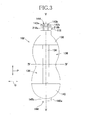
- Fig. 3 is a plan view showing the inner side of the urine receiver 102
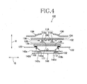
- Fig. 4 is a sectional view taken along the line IV-IV in Fig. 3
- Fig. 5 is a sectional view taken along the line V-V in Fig. 3 .
- most of the members stacked together in a thickness direction R (see Fig. 4 ) of the urine receiver 102 are illustrated to be spaced one from another.
- the urine receiver 102 has a length direction P corresponding to the vertical direction of the wearer' s body and a width direction Q which is orthogonal to the length direction P.
- the urine receiver 102 has a width which is relative large in the vicinity of its opposite end sections as viewed in the length direction P and gradually reduced in its middle section.
- the urine receiver 102 has a thickness direction R also, and comprises the container member 112, a liquid-impervious backsheet 122, a substantially non-breathable liquid-pervious sheet 124, a diffusive sheet 126, a cushion sheet 128, the urine sensor 118, a protective spacer 130 for the urine sensor 118, a protective sheet-like filter 132 for the urine sensor 118, a liquid-pervious skin-contacting sheet 134 and leak-proof barriers 136 stacked in this order from below.
- both upper and lower ends of the respective leak-proof barriers 136 are covered with first and second end sheets 138, 140 (see Fig. 3 ).
- the urine receiver 102 of Figs. 3 and 4 is provided with a feces sensor 144.
- the feces sensor 144 comprises a pair of electrodes 143a, 143b formed on thermoplastic synthetic resin films 142c, 142d, for example, by an aluminum evaporation technique.
- the films 142c, 142d are covered with a pair of cover sheets 142a, 142b.
- the cover sheets 142a, 142b are liquid-pervious so that an aqueous content of feces is permeable therethrough toward the electrodes 143a, 143b.
- the electrodes 143a, 143b extend in the length direction P in parallel to the electrodes 218a, 218b for urine detection. If a lower end section 145b of the feces sensor 144 as viewed in Figs. 3 and 5 is contaminated with feces, an aqueous content of feces permeates the cover sheet 142a and electrically connects the electrodes 143a, 143b to each other.
- a power source 116a (see Fig.1 ) provided in the wiring supplies an alarm unit with current in the form of signal asking for a treatment of feces and an exchange of the urine receiver 102.
- Fig. 6 is a plan view showing the urine sensor 118 used in the urine receiver 102 shown by Figs. 3 and 4 , the contour of the urine receiver 102 being indicated by an imaginary line.
- the urine sensor 118 comprises film 260 made of thermoplastic synthetic resin such as polyester resin, a pair of the urine detection electrodes 218a, 218b formed on one side of the film 260 and an insulator coating 170 covering most part of these electrodes 218a, 218b.
- the film 260 has a rectangular shape which is relatively long in the length direction P and a middle region thereof as viewed in the width direction Q is cut away to form a substantially rectangular opening 171.
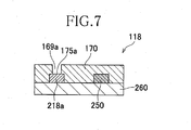
- Fig. 7 is a sectional view taken along the line VII-VII in Fig. 6 .
- the film 260 has on its upper surface, in addition to the urine detection electrode 218a, a wiring breakage detection circuit 250 and the urine detecting part 175a of the electrode 218a is exposed in the coating-free zone 169a. It should be understood that the circuit 250 is entirely covered with the insulator coating 170.
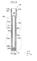
- Fig. 8 is a plan view showing the urine sensor 118 in the stage before covered with the insulator coating 170.
- urine detection electrode 218a On one side of the side portion 267a and the lower end 268a of the film 260 there is urine detection electrode 218a which is substantially L-shaped and on one side of the side portion 267b and the lower end 268b of the film 260 there is the urine detection electrode 218b which is substantially inverted L-shaped.
- the circular regions 175a, 175b of these electrodes 218a, 218b are exposed in the coating-free zones 169a, 169b as shown by Fig. 6 .
- the wiring breakage detection circuit 250 is defined between the electrodes 218a, 218b.
- the circuit 250 is electrically connected to the respective lower ends 173, 174 of the urine detection electrodes 218a, 218b and extends along the peripheral edge of the opening 171 as shown.
- a preferable example of the film 260 in such a urine sensor 118 is polyester film having a thickness in a range of 50 to 100 ⁇ m.
- the electrodes 218a, 218b may be prepared by printing conductive ink or conductive coating material in desired shapes on the film 260.
- the conductive ink or the conductive coating material may contain, as conductive materials, carbon black of 3 to 7% by weight, artificial graphite such as carbon graphite of 10 to 30% by weight and an appropriate amount of silver powder.
- Each of the preferred electrodes 218a, 218b has a width in a range of 0.5 to 2 mm, of which a value of resistance is 150 K ⁇ or less and a diameter of the coating-free zone 169a or 169b is in a range of 1 to 2 mm.
- the wiring breakage detection circuit 250 may be prepared, for example, by printing conductive ink containing carbon black of 3 to 7% by weight and artificial graphite of 5 to 10% by weight on the film 260 in a desired shape.
- This circuit 250 has a value of resistance substantially higher than those of the urine detection electrodes 218a, 218b and preferably has a width in a range of 0.3 to 1 mm and a value of resistance in a range of 2 to 10 M ⁇ .
- weak current A normally flows from the power supply 116a included in the electrical wiring 116 to the electrodes 218a, 218b and the circuit 250 electrically connected with these electrodes 218a, 218b via the clip 120.
- a circuit 110 including the wiring 116 decides that the urine detection electrodes 218a, 218b are normally functioning. If the current A is not detected, on the contrary, the circuit 110 decides that any failure, for example, wiring breakage has occurred in the urine detection electrodes 218a, 218b and thereupon causes the pump unit 108 to output a signal requesting a prompt exchange of the urine sensor 118. Referring to Fig.
- urine discharged in a range circled by an imaginary line 176 moves into the coating-free zones 169a, 169b provided on the side portions 267a, 267b, respectively, in contact with the urine detecting parts 175a, 175b and thereupon the electrode 218a on the side portion 267a and the electrode 218b on the side portion 267b are electrically connected to each other via urine. Consequently, the value of resistance between the electrodes 218a, 218b becomes lower than the value of resistance across the circuit 250, and the electric current flows not across the wiring breakage detection circuit 250 having the higher value of resistance but across urine.
- the circuit 110 detects a sudden change in the value of the electric current or the correspondingly sudden change in the value of voltage or resistance and immediately detects urination. Based on the signal generated in response to such a change, the pump unit 108 activates the pump to suck urine and then shuts down the pump as the value of resistance between the electrodes 218a, 218b sufficiently increases.
- the coating-free zones 169a, 169b for exposing the urine detecting parts 175a, 175b of the urine sensor 118 are formed on the side portions 267a, 267b in asymmetry about the center line L 1 -L 1 as illustrated to achieve an advantageous effect as follows.
- the urine receiver 102 is folded in two in the length direction P during use thereof and consequently the skin-contacting sheet 134 wet with urine is formed with a straight crease extending across the receiver 102 so as to pass through the coating-free zones 169a, 169b, the skin-contacting sheet 134 wet with urine will come in contact with the electrodes 218a, 218b and the pump unit 108 which has completed suction of urine will be erroneously activated again.
- Such erroneous activation can be easily avoided by the coating-free zones 169a, 169b arranged in asymmetric relation as shown.
- the film 260 has on the lower ends 268a, 268b and in the vicinity thereof a plurality of additional coating-free zones 169a, 169b arranged adjacent one to another. Owing to these additional coating-free zones 169a, 169b the urine receiver 102 can suck quickly an amount of urine which may rapidly flow downward immediately after urination as viewed in Fig. 6 , instead of flowing toward the liquid-pervious sheet 124.
- the layout of the coating-free zones 169a, 169b is not limited to one as illustrated and it is possible to distribute these zones 169a, 169b in a different manner on the side portions 267a, 267b in a manner different from that of Fig. 6 .
- Figs. 9 and 10 are views similar to Figs. 4 and 5 , respectively, showing one embodiment of the urine receiver 102 in which the respective members stacked one upon another in the thickness direction R are spaced one from another.
- This urine receiver 102 is provided on the outer side (i.e., lower side as viewed in Figs. 9 and 10 ) of the container member 112 with the liquid-impervious backsheet 122 extending outward from the peripheral edge of the container member 112 in the length direction P as well as in the width direction Q.
- the container member 112 is provided on its inner side with a bond sheet 200, the substantially air-impermeable liquid-pervious sheet 124, the cushion sheet 128, the urine sensor 118, the spacer 130, the filter 132, the skin-contacting sheet 134 and the leak-proof barriers 136 placed one upon another as illustrated.
- the bond sheet 200 is used to facilitate the liquid-pervious sheet 124 to be attached to the flange 152 of the container member 112.
- the container member 112 is made of polyethylene and the liquid-pervious sheet 124 is made of material having a melting temperature higher than that of polyethylene such as rayon fiber, polypropylene fiber or polyester fiber
- the bond sheet 200 is prepared from a resinous material having a melting temperature substantially same as or lower than that of the container member 112.
- the bond sheet 200 is a spun-bonded nonwoven fabric of polyethylene/polypropylene composite fiber of side-by-side type.
- the liquid-pervious sheet 124 can be easily attached to the flange 152 over the entire circumference thereof by melting polyethylene contained in the composite fiber interposed between the liquid-pervious sheet 124 and the flange 152 under compression in the thickness direction R.
- Such a bond sheet 200 may be used so as to cover the flange 152 and the upper opening entirely or so as to cover the flange 152 alone.
- the liquid-pervious sheet 124 of Figs. 9 and 10 has the both functions of the liquid-pervious sheet 124 of Figs. 4 and 5 and the diffusive sheet 126 of Figs. 4 and 5 .
- This liquid-pervious sheet 124 is formed, for example, by spun lace nonwoven fabric containing rayon fiber at a rate of 40% by weight or more with a fineness in a range of 1 to 6 dtex and a length in a range of 20 to 60 mm.
- the liquid-pervious sheet 124 may also contain thermoplastic synthetic fiber at a rate of 60% by weight or less with a fineness in a range of 1 to 6 dtex and a length in a range of 20 to 60 mm.
- thermoplastic synthetic fiber at a rate of 60% by weight or less with a fineness in a range of 1 to 6 dtex and a length in a range of 20 to 60 mm.
- the liquid-pervious sheet 124 of Figs. 9 and 10 has air-permeability in a range of 0 to 100 cc/cm 2 /sec in the wet condition and a range of 20 to 200 cc/cm 2 /sec in the dried condition.
- the liquid-pervious sheet 124 containing rayon fiber at a rate of 40% by weight or more can diffuse urine as quickly as the diffusive sheet 126 of Fig. 4 .
- the specified air-permeability is preferably met by the liquid-pervious sheet 124 itself, the specified air-permeability may be also met by the liquid-pervious sheet 124 placed upon and at least partially bonded to the bond sheet 200 which is entirely covering the opening of the container member 112 as shown by Figs. 9 and 10 .
- the cushion sheet 128 may be formed by the same material as that of the cushion sheet 128 of Figs. 4 and 5 and may have the same size as the liquid-pervious sheet 124.
- the urine sensor 118 includes the urine detection electrodes 218a, 218b (see Fig. 9 ) formed by coating the inner surface of the film 260 with conductive material.
- the film 260 extends in the length direction P substantially to the both ends of the backsheet 122.
- This film 260 is distinguished from the film 260 of Fig. 5 in that this film 260 is formed on the same surface with the paired feces detection electrodes 143a, 143b (see Fig. 9 ) also.
- the spacer 130 may be formed by the same material as that of the spacer 130 of Figs. 4 and 5 and may have the same size as the liquid-pervious sheet 124.
- the spacer 130 extends in the length direction P but does not extend downward as far as the spacer 130 might cover the feces detecting elements 144d, 144e (see Fig. 11 ) in the feces detection electrodes 143a, 143b.
- the filter 132 and the skin-contacting sheet 134 may be formed by the same materials as those for the filter 132 and the skin-contacting sheet 134 of Figs. 4 and 5 , respectively.
- the filter 132 has the same size as the liquid-pervious sheet 124.
- the skin-contacting sheet 134 has the same dimension as that of the liquid-pervious sheet 124 in the length direction P but has a dimension which is larger than the liquid-pervious sheet 124 and substantially same as the backsheet 122 in the width direction Q.
- the ends of the urine receiver 102 opposed to each other in the length direction P are respectively provided with the end sheets 138, 140 (see Fig. 10 ). These end sheets 138, 140 respectively cover the ends (not shown) of the leak-proof barrier 136 which is opposed to each other in the length direction P in the same manner as in Fig. 3 .
- the liquid-pervious sheet 124, the cushion sheet 128, the urine sensor 118, the spacer 130, the filter 132 and the skin-contacting sheet 134 stacked one on another are bonded one to another in the same manner as in Figs. 4 and 5 .
- a portion of the backsheet 122 extending outward beyond the flange 152 of the container member 112 is bonded to the skin-contacting sheet 134 and the other sheets and preferably further to the outer surface of.the bottom of the container member 112.
- the leak-proof barriers 136 are bonded to the skin-contacting sheet 134 and a portion of the backsheet 122 extending outward beyond the peripheral edge of the skin-contacting sheet 134.
- the feces detecting element 144d, 144e of the feces detection electrodes 143a, 143b are covered with nonwoven fabric cover sheet 201 (see Fig. 10 ) allowing the moisture content in feces to permeate therethrough.
- the end sheet 140 lying above the cover sheet 201 is formed with a through-hole 202 so that the end sheet 140 might cover the detecting elements 144d, 144e.
- the through-hole 202 is to be located in the vicinity of the anus of the wearer of the urine receiver 102.
- Fig. 11 is a plan view showing the urine sensor 118 used in the urine receiver 102 of Figs. 9 and 10 as partially in sectional view.
- the urine sensor 118 comprises a pair of urine detection electrodes 218a, 218b formed on the inner surface of the liquid-impervious thermoplastic synthetic resin film 260, a pair of feces detection electrodes 143a, 143b and a wiring breakage detection circuit 250. Most part of the electrodes 218a, 218b, 143a, 143b and the entire wiring breakage detection circuit 250 are covered with the insulator coating 170 partially shown in a sectional view.
- the film 260 is formed in the middle region as viewed in the width direction Q with two openings 171, 172 aligned with each other in the length direction P.
- a bridge 183 serving to prevent deformation of the film 260 is defined between these openings 171, 172.
- the pair of electrodes 218a, 218b as well as the pair of electrodes 143a, 143b are formed so as to be opposed to each other about the openings 171, 172, respectively, and the wiring breakage detection circuit 250 extends along the respective edges of the openings 171, 172 so as to connect the opposite ends of the pair of urine detection electrodes 218a, 218b. Referring to Fig.
- the urine detection electrodes 218a, 218b respectively have the urine detecting parts 175a, 175b exposed in zones 169a free from the insulator coating 170 while the feces detection electrodes 143a, 143b respectively have feces detecting elements 144d, 144e in the vicinity of the respective lower ends of the urine detection electrodes 218a, 218b and not covered with the coating 170.
- These urine detecting parts 175a, 175b and the feces detecting elements 144d, 144e are substantially symmetric about the center line L 1 -L 1 .
- the urine detection electrodes 218a, 218b are formed on the upper ends thereof with connectors 218c, 218d while the feces detection electrodes 143a, 143b are formed on the upper ends with connectors 244a, 244b. These connectors 218c, 218d and 244a, 244b are held by the clip 120 of Fig. 2 .
- the urine detecting parts 175a, 175b are electrically connected to each other via urine between the paired urine detection electrodes 218a, 218b, electric current flows between the urine detection electrodes 218a, 218b as in the case of the urine sensor of Fig. 6 and thereupon the pump unit 108 is activated.
- the feces detecting elements 144d, 144e are electrically connected to each other via aqueous content in feces between the paired feces detection electrodes 143a, 143b, electric current flows between the feces detection electrodes 143a, 143b and thereupon the pump unit 108 is informed of defecation as in the case of the urine receiver 102 of Figs. 4 and 5 .
- weak current normally flows in the wiring breakage detection circuit 250 as in the case of the urine sensor 118 of Fig. 8 so that a wiring breakage alarm device (not shown) included in the pump unit 108 is activated due to a change of electric current based on a damage of the urine detection electrodes 218a and/or 218b and urges to set off exchange of the urine receiver 102.
- the present invention presents a urine receiver which can efficiently and quickly suck urine.
Landscapes
- Health & Medical Sciences (AREA)
- Life Sciences & Earth Sciences (AREA)
- Public Health (AREA)
- Veterinary Medicine (AREA)
- Engineering & Computer Science (AREA)
- Biomedical Technology (AREA)
- Heart & Thoracic Surgery (AREA)
- Epidemiology (AREA)
- Animal Behavior & Ethology (AREA)
- Vascular Medicine (AREA)
- General Health & Medical Sciences (AREA)
- Nursing (AREA)
- Orthopedic Medicine & Surgery (AREA)
- Orthopedics, Nursing, And Contraception (AREA)
- Investigating Or Analyzing Materials By The Use Of Electric Means (AREA)
- Investigating Or Analysing Biological Materials (AREA)
Abstract
Description
- The present invention relates generally to a urine sensor to be used with an automatic urine disposal system for persons such as bedridden aged, bedridden patient and physically disabled persons for whom it is difficult to control timing of urination and/or to make a disposal of urine after discharged.
- It is often difficult for those persons as have been described above to control timing of urination on his or her own will and/or to make disposal of urine after discharged by his or her own ability. In order to overcome the difficulties for such persons, there has already been proposed an automatic urine disposal system comprising a urine receiver to be put against a wearer's crotch around a urethral, suction means such as a suction pump provided separately of the urine receiver adapted to guide the amount of urine collected by the suction means in the urine receiver to a urine reservoir. The suction pump evacuates air within the hermetically sealed urine reservoir to generate a differential pressure between the urine receiver and the urine reservoir so that the differential pressure causes the amount of urine within the urine receiver to be guided into the urine reservoir.
- This urine receiver of prior art includes a urine sensor to detect urination and thereupon to activate the suction pump. The urine sensor includes a pair of electrodes and a urination detection circuit adapted to become live and to activate the suction pump when the paired electrodes are electrically connected to each other via urine. The urine receiver of this type, for example, disclosed by Japanese Unexamined Patent Application Publication No.
2004-267517A - PATENT DOCUMENT 1: Japanese Unexamined Patent Application Publication No.
2004-267517A - However, the electrodes used in this urine sensor of prior art have a relatively large area entirely exposed and consequentially the suction pump may erroneously be activated due to a contact between the electrodes and the topsheet on which an amount of urine stays. In addition, depending on a posture of a wearer of the urine receiver, the topsheet may come in contact with the urine sensor and erroneously activate the suction pump.
- In view of the problems described above, it is an object of the present invention to prevent the urine sensor included in the urine receiver from erroneously activating a suction pump.
- According to the present invention, there is provided a urine sensor to be used in a urine receiver comprising a urine collecting member to be put on a wearer's body with the inner side placed against a urethral and a skin thereabout and a urine detecting member to be interposed between the wearer' s skin and the urine collecting member and serving to detect urine discharged from the urethral, wherein the urine receiver is connected to vacuum suction means provided separately of the urine receiver so that the vacuum suction means may be activated in response to a detection signal output from the urine detecting member to suck the urine into the urine collecting member.
- The urine sensor comprises thermoplastic synthetic resin film having a length direction, a width direction and a thickness direction being orthogonal one to another, a pair of electrodes formed on a surface of the film and an electrically insulating coating formed on the surface to cover the electrodes, the film being formed along a center line bisecting the width of the film with an opening and both side portions of the film along the opening being respectively provided with the electrodes extending in the length direction, each of the electrodes being provided at one end of the opposite ends thereof as viewed in the length direction with an electrical connector means to be connected to the vacuum suction means, the insulating coating being formed between the opposite ends of the electrodes with a plurality of through-holes in which the electrodes may come in contact with the urine flowing into the through-holes.
- According to one embodiment, respective ends of the pair of electrodes opposed to the one ends are electrically connected to each other via a circuit having an electric resistance higher than those of the electrodes.
- According to another embodiment, each of the electrodes has an electric resistance of 150 KΩ or less and the circuit has an electric resistance of in a range of 2 to 10 MΩ.
- According to still another embodiment, the urine sensor includes a pair of feces detection electrodes provided separately of a pair of the electrodes so as to extend in parallel to these electrodes and the feces detection electrodes are also covered with the electrically insulating coating including coating-free zones in the vicinity of the ends opposed to the respective one ends so that the coating-free zones are allowed to contact feces to be detected.
- According to further another embodiment, the electrodes, the circuit and the feces detection electrodes are formed by conductive ink or conductive coating material.
- According to an embodiment of the present invention, the electrodes for the urine sensor are formed on the surface of the thermoplastic synthetic resin film so as to extend on both sides of the opening formed in this film and covered with the insulator coating. The insulator coating is formed with a plurality of through-holes in which the electrodes are partially exposed and, when these exposed portions of the electrodes are wet with urine, the pair of electrodes are electrically connected to each other. In this way, urination can be reliably detected without erroneously activating the vacuum suction means.
- According to an embodiment of the present invention wherein the respective ends of the pair of electrodes are electrically connected to each other via the circuit having an electrical resistance higher than those of these electrodes, this circuit can be used as a means to detect whether a wiring breakage occurs or not in these paired electrodes.
- According to an embodiment of the present invention wherein feces can be detected, the urine receiver can be replaced in a timely manner before it loses a capability of urine collection.
-
- [
FIG. 1] Fig. 1 is a schematic diagram illustrating a construction of an automatic urine disposal system including a urine receiver. - [
FIG. 2] Fig. 2 is a diagram showing the urine receiver as put on a wearer. - [
FIG. 3] Fig. 3 is a plan view of the urine receiver. - [
FIG. 4] Fig. 4 is a sectional view taken along the line IV-IV inFig. 3 . - [
FIG. 5] Fig. 5 is a sectional view taken along the line V-V inFig. 3 . - [
FIG. 6] Fig. 6 is a plan view of a urine sensor. - [
FIG. 7] Fig. 7 is a sectional view taken along the line VII-VII inFig. 6 . - [
FIG. 8] Fig. 8 is a plan view of the urine sensor not covered with insulator coating. - [
FIG. 9] Fig. 9 is a view similar toFig. 4 , showing one embodiment of the urine receiver. - [
FIG. 10] Fig. 10 is a view similar toFig. 5 , showing another embodiment of the urine receiver. - [
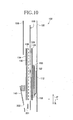
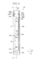
FIG. 11] Fig. 11 is a view similar toFig. 6 , showing one embodiment of the urine sensor. -
- 100a
- urine suction mechanism
- 102
- urine receiver
- 112
- urine collecting member (container member)
- 118
- urine sensor
- 143a, 143b
- feces detection electrodes
- 169a, 169b
- coating-free zones
- 170
- insulator coating
- 171
- opening
- 172
- opening
- 175a, 175b
- urine detecting parts
- 218a, 218b
- urine detection electrodes
- 250
- wiring breakage detection circuit
- 260
- film
- P
- length direction
- Q
- width direction
- R
- thickness direction
- Details of the urine sensor according to the present invention will be more fully understood from the description given hereunder in reference with the accompanying drawings.
-
Fig. 1 is a diagram schematically illustrating a construction of an automaticurine disposal system 100 including aurine suction mechanism 100a to be combined with aurine receiver 102 according to the invention. While theurine receiver 102 has an inner side member facing the wearer's skin and an outer side member facing the wearer's clothes, the outer side member is shown as partially broken away. - The automatic
urine disposal system 100 is adapted to collect urine discharged from the wearer (not shown) by theurine receiver 102 for disposal. Theurine receiver 102 includes a tray-like container member 112 to face the wearer's skin in the vicinity of the urethral and to receive urine discharged while the automaticurine disposal system 100 includes theurine suction mechanism 100a comprising various components such as ajoint member 104, aurine guide tube 106 and apump unit 108. - The
pump unit 108 comprises aurine reservoir 106a adapted to take over the amount of urine having been collected by theurine receiver 102 and to pool this,electric wiring 116 serving for an electrical connection of aurine sensor 118 provided on theurine receiver 102 for detection of urination to thepump unit 108, and a suction pump (not shown) adapted to be activated in response to a signal transmitted from theurine sensor 118 via thewiring 116. In theurine receiver 102, a peripheral wall of thecontainer member 112 is formed with a urine evacuation opening 114 and theurine guide tube 106 is connected to thisopening 114 by means of thejoint member 104. Thewiring 116 extending from thepump unit 108 is provided at its distal end with aclip 120 serving for electric connections ofelectrodes Fig. 3 ) of theurine sensor 118 and others provided in theurine receiver 102 to thewiring 116. Such an automaticurine disposal system 100 detects a urination by theurine sensor 118 and the suction pump included in thepump unit 108 is activated in response to the detection signal. Thepump unit 108 vacuums up air within theurine reservoir 106a so that the urine discharged from the wearer may be forcibly guided into thecontainer member 112 and eventually collected into theurine reservoir 106a via thejoint member 104 and theurine guide tube 106. -
Fig. 2 is a diagram exemplarily illustrating how to wear theurine receiver 102. Theurine receiver 102 is fixed to the inner side of acrotch belt section 301 constituting a T-shapedbelt 300 by means of, for example, a pressure-sensitive adhesive or a mechanical fastener known in a trade name of Magic Tape. Being put on the wearer's body, a major part of thecontainer member 112 of theurine receiver 102 extends in the vertical direction of the wearer's body with the inner side facing the urethral and the skin extending therearound while a lower end of thecontainer member 112 extends toward the anus so as to describe a gentle curve. In the T-shapedbelt 300, longitudinally opposite ends of awaist belt section 302 are detachably connected to each other by a suitable connector means 303 such as a mechanical fastener while thecrotch belt section 301 has end stitched together with thewaist belt section 302 and the other end detachably connected to thewaist belt section 302 by means of themechanical fastener 304. It should be noted here that the chassis for theurine receiver 102 is not limited to the illustrated T-shaped belt and the other appropriate means such as the open- or pants-type diaper, the diaper cover or the pants for incontinent patient can be used as the chassis for theurine receiver 102. -
Fig. 3 is a plan view showing the inner side of theurine receiver 102,Fig. 4 is a sectional view taken along the line IV-IV inFig. 3 andFig. 5 is a sectional view taken along the line V-V inFig. 3 . InFigs. 4 and5 , most of the members stacked together in a thickness direction R (seeFig. 4 ) of theurine receiver 102 are illustrated to be spaced one from another. - Referring to
Figs. 3 and4 , theurine receiver 102 has a length direction P corresponding to the vertical direction of the wearer' s body and a width direction Q which is orthogonal to the length direction P. Theurine receiver 102 has a width which is relative large in the vicinity of its opposite end sections as viewed in the length direction P and gradually reduced in its middle section. Theurine receiver 102 has a thickness direction R also, and comprises thecontainer member 112, a liquid-impervious backsheet 122, a substantially non-breathable liquid-pervious sheet 124, adiffusive sheet 126, acushion sheet 128, theurine sensor 118, aprotective spacer 130 for theurine sensor 118, a protective sheet-like filter 132 for theurine sensor 118, a liquid-pervious skin-contactingsheet 134 and leak-proof barriers 136 stacked in this order from below. - As seen with the
urine receiver 102 flattened, both upper and lower ends of the respective leak-proof barriers 136 are covered with first andsecond end sheets 138, 140 (seeFig. 3 ). - If the skin-contacting
sheet 134 is contaminated with feces discharged from the wearer of theurine receiver 102, it will be no more possible for theurine receiver 102 to absorb urine. In order to deal with this problem, theurine receiver 102 ofFigs. 3 and4 is provided with afeces sensor 144. Referring toFig. 4 , thefeces sensor 144 comprises a pair ofelectrodes synthetic resin films films cover sheets cover sheets electrodes feces sensor 144, theelectrodes electrodes lower end section 145b of thefeces sensor 144 as viewed inFigs. 3 and5 is contaminated with feces, an aqueous content of feces permeates thecover sheet 142a and electrically connects theelectrodes power source 116a (seeFig.1 ) provided in the wiring supplies an alarm unit with current in the form of signal asking for a treatment of feces and an exchange of theurine receiver 102. -
Fig. 6 is a plan view showing theurine sensor 118 used in theurine receiver 102 shown byFigs. 3 and4 , the contour of theurine receiver 102 being indicated by an imaginary line. Theurine sensor 118 comprisesfilm 260 made of thermoplastic synthetic resin such as polyester resin, a pair of theurine detection electrodes film 260 and aninsulator coating 170 covering most part of theseelectrodes film 260 has a rectangular shape which is relatively long in the length direction P and a middle region thereof as viewed in the width direction Q is cut away to form a substantiallyrectangular opening 171. Such afilm 260 inFig. 6 is contoured by anupper end 266 to be held by theclip 120,side portions upper end 266 and along theopening 171 so as to extend on both sides a center line L1-L1 bisecting the width of theurine sensor 118, andlower ends side portions joint portion 268c. Most part of the surface of thefilm 260 carrying theelectrodes insulator coating 170 except theupper end 266 at which theelectrodes side portions free zones insulator coating 170 is formed and theurine detecting parts electrode -
Fig. 7 is a sectional view taken along the line VII-VII inFig. 6 . As shown, thefilm 260 has on its upper surface, in addition to theurine detection electrode 218a, a wiringbreakage detection circuit 250 and theurine detecting part 175a of theelectrode 218a is exposed in the coating-free zone 169a. It should be understood that thecircuit 250 is entirely covered with theinsulator coating 170. -
Fig. 8 is a plan view showing theurine sensor 118 in the stage before covered with theinsulator coating 170. On one side of theside portion 267a and thelower end 268a of thefilm 260 there isurine detection electrode 218a which is substantially L-shaped and on one side of theside portion 267b and thelower end 268b of thefilm 260 there is theurine detection electrode 218b which is substantially inverted L-shaped. Thecircular regions electrodes free zones Fig. 6 . The wiringbreakage detection circuit 250 is defined between theelectrodes circuit 250 is electrically connected to the respective lower ends 173, 174 of theurine detection electrodes opening 171 as shown. - A preferable example of the
film 260 in such aurine sensor 118 is polyester film having a thickness in a range of 50 to 100 µm. Theelectrodes film 260. The conductive ink or the conductive coating material may contain, as conductive materials, carbon black of 3 to 7% by weight, artificial graphite such as carbon graphite of 10 to 30% by weight and an appropriate amount of silver powder. Each of thepreferred electrodes free zone breakage detection circuit 250 may be prepared, for example, by printing conductive ink containing carbon black of 3 to 7% by weight and artificial graphite of 5 to 10% by weight on thefilm 260 in a desired shape. Thiscircuit 250 has a value of resistance substantially higher than those of theurine detection electrodes - When the
urine sensor 118 ofFig. 6 is used in theurine receiver 102, weak current A normally flows from thepower supply 116a included in theelectrical wiring 116 to theelectrodes circuit 250 electrically connected with theseelectrodes clip 120. In response to such weak current A, acircuit 110 including thewiring 116 decides that theurine detection electrodes circuit 110 decides that any failure, for example, wiring breakage has occurred in theurine detection electrodes pump unit 108 to output a signal requesting a prompt exchange of theurine sensor 118. Referring toFig. 6 , urine discharged in a range circled by animaginary line 176 moves into the coating-free zones side portions urine detecting parts electrode 218a on theside portion 267a and theelectrode 218b on theside portion 267b are electrically connected to each other via urine. Consequently, the value of resistance between theelectrodes circuit 250, and the electric current flows not across the wiringbreakage detection circuit 250 having the higher value of resistance but across urine. When electric current B flowing across urine becomes remarkably higher than the electric current A flowing across thecircuit 250, thecircuit 110 detects a sudden change in the value of the electric current or the correspondingly sudden change in the value of voltage or resistance and immediately detects urination. Based on the signal generated in response to such a change, thepump unit 108 activates the pump to suck urine and then shuts down the pump as the value of resistance between theelectrodes - In the
urine sensor 118 ofFig. 6 , the coating-free zones urine detecting parts urine sensor 118 are formed on theside portions urine receiver 102 is folded in two in the length direction P during use thereof and consequently the skin-contactingsheet 134 wet with urine is formed with a straight crease extending across thereceiver 102 so as to pass through the coating-free zones sheet 134 wet with urine will come in contact with theelectrodes pump unit 108 which has completed suction of urine will be erroneously activated again. Such erroneous activation can be easily avoided by the coating-free zones free zones film 260 has on the lower ends 268a, 268b and in the vicinity thereof a plurality of additional coating-free zones free zones urine receiver 102 can suck quickly an amount of urine which may rapidly flow downward immediately after urination as viewed inFig. 6 , instead of flowing toward the liquid-pervious sheet 124. The layout of the coating-free zones zones side portions Fig. 6 . -
Figs. 9 and10 are views similar toFigs. 4 and5 , respectively, showing one embodiment of theurine receiver 102 in which the respective members stacked one upon another in the thickness direction R are spaced one from another. Thisurine receiver 102 is provided on the outer side (i.e., lower side as viewed inFigs. 9 and10 ) of thecontainer member 112 with the liquid-impervious backsheet 122 extending outward from the peripheral edge of thecontainer member 112 in the length direction P as well as in the width direction Q. Thecontainer member 112 is provided on its inner side with abond sheet 200, the substantially air-impermeable liquid-pervious sheet 124, thecushion sheet 128, theurine sensor 118, thespacer 130, thefilter 132, the skin-contactingsheet 134 and the leak-proof barriers 136 placed one upon another as illustrated. - The
bond sheet 200 is used to facilitate the liquid-pervious sheet 124 to be attached to theflange 152 of thecontainer member 112. For example, if thecontainer member 112 is made of polyethylene and the liquid-pervious sheet 124 is made of material having a melting temperature higher than that of polyethylene such as rayon fiber, polypropylene fiber or polyester fiber, thebond sheet 200 is prepared from a resinous material having a melting temperature substantially same as or lower than that of thecontainer member 112. For example, thebond sheet 200 is a spun-bonded nonwoven fabric of polyethylene/polypropylene composite fiber of side-by-side type. The liquid-pervious sheet 124 can be easily attached to theflange 152 over the entire circumference thereof by melting polyethylene contained in the composite fiber interposed between the liquid-pervious sheet 124 and theflange 152 under compression in the thickness direction R. Such abond sheet 200 may be used so as to cover theflange 152 and the upper opening entirely or so as to cover theflange 152 alone. - The liquid-
pervious sheet 124 ofFigs. 9 and10 has the both functions of the liquid-pervious sheet 124 ofFigs. 4 and5 and thediffusive sheet 126 ofFigs. 4 and5 . This liquid-pervious sheet 124 is formed, for example, by spun lace nonwoven fabric containing rayon fiber at a rate of 40% by weight or more with a fineness in a range of 1 to 6 dtex and a length in a range of 20 to 60 mm. The liquid-pervious sheet 124 may also contain thermoplastic synthetic fiber at a rate of 60% by weight or less with a fineness in a range of 1 to 6 dtex and a length in a range of 20 to 60 mm. Similarly to the liquid-pervious sheet 124 ofFig. 4 , the liquid-pervious sheet 124 ofFigs. 9 and10 has air-permeability in a range of 0 to 100 cc/cm2/sec in the wet condition and a range of 20 to 200 cc/cm2/sec in the dried condition. The liquid-pervious sheet 124 containing rayon fiber at a rate of 40% by weight or more can diffuse urine as quickly as thediffusive sheet 126 ofFig. 4 . While the specified air-permeability is preferably met by the liquid-pervious sheet 124 itself, the specified air-permeability may be also met by the liquid-pervious sheet 124 placed upon and at least partially bonded to thebond sheet 200 which is entirely covering the opening of thecontainer member 112 as shown byFigs. 9 and10 . - The
cushion sheet 128 may be formed by the same material as that of thecushion sheet 128 ofFigs. 4 and5 and may have the same size as the liquid-pervious sheet 124. - The
urine sensor 118 includes theurine detection electrodes Fig. 9 ) formed by coating the inner surface of thefilm 260 with conductive material. Thefilm 260 extends in the length direction P substantially to the both ends of thebacksheet 122. Thisfilm 260 is distinguished from thefilm 260 ofFig. 5 in that thisfilm 260 is formed on the same surface with the pairedfeces detection electrodes Fig. 9 ) also. - The
spacer 130 may be formed by the same material as that of thespacer 130 ofFigs. 4 and5 and may have the same size as the liquid-pervious sheet 124. Thespacer 130 extends in the length direction P but does not extend downward as far as thespacer 130 might cover thefeces detecting elements Fig. 11 ) in thefeces detection electrodes - The
filter 132 and the skin-contactingsheet 134 may be formed by the same materials as those for thefilter 132 and the skin-contactingsheet 134 ofFigs. 4 and5 , respectively. Thefilter 132 has the same size as the liquid-pervious sheet 124. The skin-contactingsheet 134 has the same dimension as that of the liquid-pervious sheet 124 in the length direction P but has a dimension which is larger than the liquid-pervious sheet 124 and substantially same as thebacksheet 122 in the width direction Q. - The ends of the
urine receiver 102 opposed to each other in the length direction P are respectively provided with theend sheets 138, 140 (seeFig. 10 ). Theseend sheets proof barrier 136 which is opposed to each other in the length direction P in the same manner as inFig. 3 . - Referring to
Figs. 8 and9 , the liquid-pervious sheet 124, thecushion sheet 128, theurine sensor 118, thespacer 130, thefilter 132 and the skin-contactingsheet 134 stacked one on another are bonded one to another in the same manner as inFigs. 4 and5 . However, a portion of thebacksheet 122 extending outward beyond theflange 152 of thecontainer member 112 is bonded to the skin-contactingsheet 134 and the other sheets and preferably further to the outer surface of.the bottom of thecontainer member 112. The leak-proof barriers 136 are bonded to the skin-contactingsheet 134 and a portion of thebacksheet 122 extending outward beyond the peripheral edge of the skin-contactingsheet 134. - Referring to
Fig. 10 , thefeces detecting element feces detection electrodes Fig. 10 ) allowing the moisture content in feces to permeate therethrough. Theend sheet 140 lying above thecover sheet 201 is formed with a through-hole 202 so that theend sheet 140 might cover the detectingelements hole 202 is to be located in the vicinity of the anus of the wearer of theurine receiver 102. -
Fig. 11 is a plan view showing theurine sensor 118 used in theurine receiver 102 ofFigs. 9 and10 as partially in sectional view. Theurine sensor 118 comprises a pair ofurine detection electrodes synthetic resin film 260, a pair offeces detection electrodes breakage detection circuit 250. Most part of theelectrodes breakage detection circuit 250 are covered with theinsulator coating 170 partially shown in a sectional view. Thefilm 260 is formed in the middle region as viewed in the width direction Q with twoopenings bridge 183 serving to prevent deformation of thefilm 260 is defined between theseopenings electrodes electrodes openings breakage detection circuit 250 extends along the respective edges of theopenings urine detection electrodes Fig. 11 , theurine detection electrodes urine detecting parts zones 169a free from theinsulator coating 170 while thefeces detection electrodes feces detecting elements urine detection electrodes coating 170. Theseurine detecting parts feces detecting elements urine detection electrodes connectors feces detection electrodes connectors connectors clip 120 ofFig. 2 . When theurine detecting parts urine detection electrodes urine detection electrodes Fig. 6 and thereupon thepump unit 108 is activated. When thefeces detecting elements feces detection electrodes feces detection electrodes pump unit 108 is informed of defecation as in the case of theurine receiver 102 ofFigs. 4 and5 . - It should be noted that weak current normally flows in the wiring
breakage detection circuit 250 as in the case of theurine sensor 118 ofFig. 8 so that a wiring breakage alarm device (not shown) included in thepump unit 108 is activated due to a change of electric current based on a damage of theurine detection electrodes 218a and/or 218b and urges to set off exchange of theurine receiver 102. - The present invention presents a urine receiver which can efficiently and quickly suck urine.
Claims (8)
- A urine disposal system(100) comprising a urine receiver (102) to receive discharged urine and a urine suction mechanism (100a), wherein:said urine receiver (102) comprises a urine collecting member (112) to be put on a wearer's body with the inner side placed against a urethral and a skin thereabout and a urine sensor (118) to be interposed between said skin and said urine collecting member and serving to detect urine discharged from said urethral, wherein said urine receiver(102) is connected to said urine suction mechanism(100a) provided separately of said urine receiver so that said urine suction mechanism may be activated in response to a detection signal output from said urine detecting member to suck said urine into said urine collecting member(112), and wherein:said urine sensor (118) further comprises thermoplastic synthetic resin film(260) having a length direction (P), a width direction(Q) and a thickness direction being orthogonal one to another, a pair of electrodes(218a,218b) formed on a surface of said film and an electrically insulating coating(170) formed on said surface to cover said electrodes, said film being formed along a center line bisecting the width of said film with an opening(171) and both side portions(267a,267b) of said film along said opening being respectively provided with said electrodes extending in said length direction, each of said electrodes being provided at one end of the opposite ends thereof as viewed in said length direction with an electrical connector means to be connected to said urine suction mechanism.
- The Urine disposal system defined by Claim 1, wherein said urine suction mechanism (100a) comprises a pump unit (108), a joint member (104) and a urine guide tube (106) connected to said urine collecting member (112) by means of said joint member.
- The Urine disposal system defined by claim 2, wherein said pump unit (108) comprises a urine reservoir (106a) adapted to take over and pool the amount of urine having been collected by said urine receiver (102), an electric wiring (116) serving for an electrical connection of said urine sensor and a suction pump adapted to be activated in response to a signal transmitted from said urine sensor via said electric wiring.
- The Urine disposal system defined by any one of claims 1-3, wherein said insulating coating is formed between said opposite ends of said electrodes with a plurality of through-holes in which said electrodes may come in contact with said urine flowing into said through-holes.
- The urine disposal system defined by Claims 1-4, wherein respective ends of said pair of electrodes opposed to said one ends are electrically connected to each other via a circuit having an electric resistance higher than those of said electrodes.
- The urine disposal system defined by any one of Claims 1-5, wherein each of said electrodes has an electric resistance of 150 KΩ or less and said circuit has an electric resistance of in a range of 2 to 10 MΩ.
- The urine disposal system defined by any one of claims 1-6, wherein said urine sensor includes a pair of feces detection electrodes provided separately of said pair of electrodes so as to extend in parallel to said electrodes and said feces detection electrodes are also covered with said electrically insulating coating including coating-free zones in the vicinity of said ends opposed to said respective one ends so that said coating-free zones are allowed to contact feces to be detected.
- The urine disposal system defined by any one of Claims 1-7, wherein said electrodes, said circuit and said feces detection electrodes are formed by conductive ink or conductive coating material.
Applications Claiming Priority (3)
| Application Number | Priority Date | Filing Date | Title |
|---|---|---|---|
| JP2005204978 | 2005-07-13 | ||
| JP2006187166A JP4979999B2 (en) | 2005-07-13 | 2006-07-06 | Urine sensor |
| EP06768203A EP1905400B1 (en) | 2005-07-13 | 2006-07-13 | Urine sensor |
Related Parent Applications (1)
| Application Number | Title | Priority Date | Filing Date |
|---|---|---|---|
| EP06768203.9 Division | 2006-07-13 |
Publications (2)
| Publication Number | Publication Date |
|---|---|
| EP2478877A2 true EP2478877A2 (en) | 2012-07-25 |
| EP2478877A3 EP2478877A3 (en) | 2012-08-22 |
Family
ID=37637224
Family Applications (2)
| Application Number | Title | Priority Date | Filing Date |
|---|---|---|---|
| EP12155507A Withdrawn EP2478877A3 (en) | 2005-07-13 | 2006-07-13 | Urine sensor |
| EP06768203A Expired - Lifetime EP1905400B1 (en) | 2005-07-13 | 2006-07-13 | Urine sensor |
Family Applications After (1)
| Application Number | Title | Priority Date | Filing Date |
|---|---|---|---|
| EP06768203A Expired - Lifetime EP1905400B1 (en) | 2005-07-13 | 2006-07-13 | Urine sensor |
Country Status (6)
| Country | Link |
|---|---|
| US (1) | US7755497B2 (en) |
| EP (2) | EP2478877A3 (en) |
| JP (1) | JP4979999B2 (en) |
| KR (1) | KR101273195B1 (en) |
| TW (1) | TWI307275B (en) |
| WO (1) | WO2007007844A1 (en) |
Families Citing this family (160)
| Publication number | Priority date | Publication date | Assignee | Title |
|---|---|---|---|---|
| JP5037043B2 (en) * | 2005-07-14 | 2012-09-26 | ユニ・チャーム株式会社 | Moisture detection sensor |
| US20080262453A1 (en) * | 2007-04-18 | 2008-10-23 | Mcginnis William J | Remote monitoring diaper system, kit and method of using |
| US20080262452A1 (en) * | 2007-04-18 | 2008-10-23 | Mcginnis William J | Standalone smart disposable diaper, kit and method |
| JP5154136B2 (en) | 2007-04-26 | 2013-02-27 | ユニ・チャーム株式会社 | Absorbent articles |
| JP4941985B2 (en) * | 2007-09-18 | 2012-05-30 | パラマウントベッド株式会社 | Control device for vacuum suction urine collection device |
| JP4384694B2 (en) * | 2008-02-13 | 2009-12-16 | ユニ・チャーム株式会社 | Urine sucking device |
| JP5358103B2 (en) * | 2008-02-14 | 2013-12-04 | ユニ・チャーム株式会社 | Automatic urine treatment equipment |
| CN102196787A (en) * | 2008-09-19 | 2011-09-21 | 尤妮佳股份有限公司 | Urine receiver and wearing article |
| JP5346193B2 (en) * | 2008-09-19 | 2013-11-20 | ユニ・チャーム株式会社 | Wearing article |
| AU2009292872B2 (en) * | 2008-09-19 | 2015-06-11 | Uni-Charm Corporation | Excretory fluid detection device |
| US8237573B2 (en) | 2010-03-25 | 2012-08-07 | Bhatia Saket S | Alarm unit for monitoring or detection of an analyte |
| JP5457904B2 (en) * | 2010-03-26 | 2014-04-02 | ユニ・チャーム株式会社 | Urine processing structure |
| BR112012025259A2 (en) | 2010-04-08 | 2019-09-24 | Koninl Philips Electronics Nv | "sensor equipment, clothing item, method and computer program" |
| GB201022031D0 (en) * | 2010-12-23 | 2011-02-02 | Sca Hygiene Prod Ab | Absorbent article comprising a liquid discharge detection sensor |
| US9323799B2 (en) | 2013-09-21 | 2016-04-26 | Oracle International Corporation | Mechanism to run OLTP workload on in-memory database under memory pressure |
| KR101382138B1 (en) * | 2013-10-04 | 2014-04-17 | 조영숙 | Smart diaper |
| US11090183B2 (en) | 2014-11-25 | 2021-08-17 | Purewick Corporation | Container for collecting liquid for transport |
| US10952889B2 (en) | 2016-06-02 | 2021-03-23 | Purewick Corporation | Using wicking material to collect liquid for transport |
| US11806266B2 (en) | 2014-03-19 | 2023-11-07 | Purewick Corporation | Apparatus and methods for receiving discharged urine |
| US10390989B2 (en) | 2014-03-19 | 2019-08-27 | Purewick Corporation | Apparatus and methods for receiving discharged urine |
| US10226376B2 (en) | 2014-03-19 | 2019-03-12 | Purewick Corporation | Apparatus and methods for receiving discharged urine |
| US10531977B2 (en) | 2014-04-17 | 2020-01-14 | Coloplast A/S | Thermoresponsive skin barrier appliances |
| US11141100B2 (en) | 2015-12-23 | 2021-10-12 | Coloplast A/S | Moisture assessment system and method for wound care |
| US10690655B2 (en) * | 2016-02-18 | 2020-06-23 | Ur24 Technology, Llc | Automated urine collector-analyzer |
| US10682124B2 (en) | 2016-02-18 | 2020-06-16 | Ur24 Technology, Llc | Automated collection and analysis of body fluids |
| JP6839452B2 (en) | 2016-02-18 | 2021-03-10 | ユーアール24 テクノロジー,エルエルシー | Automatic Urine Collector-Analyst |
| CN205964299U (en) * | 2016-03-10 | 2017-02-22 | 小贵族科技有限公司 | An electronic moisture absorbent product |
| USD928946S1 (en) | 2016-06-02 | 2021-08-24 | Purewick Corporation | Urine receiving apparatus |
| US10376406B2 (en) | 2016-07-27 | 2019-08-13 | Purewick Corporation | Male urine collection device using wicking material |
| US10973678B2 (en) | 2016-07-27 | 2021-04-13 | Purewick Corporation | Apparatus and methods for receiving discharged urine |
| CN110612075B (en) | 2017-01-31 | 2022-09-09 | 普利维克公司 | Apparatus and method for receiving excreted urine |
| EP3357414A1 (en) * | 2017-02-01 | 2018-08-08 | Universitat Rovira I Virgili | Biosensor for detecting biological fluid |
| WO2018152156A1 (en) | 2017-02-14 | 2018-08-23 | Sage Products, Llc | Devices and methods for urine collection |
| WO2018221530A1 (en) | 2017-05-30 | 2018-12-06 | 花王株式会社 | Wearable article equipped with sensor |
| US11721436B2 (en) | 2017-05-30 | 2023-08-08 | Kao Corporation | Care schedule proposal device |
| WO2019051118A1 (en) | 2017-09-07 | 2019-03-14 | Smardii, Inc. | Systems and methods of a health monitoring device |
| USD882768S1 (en) | 2017-09-08 | 2020-04-28 | Sage Products, Llc | Urine collection device |
| JP6941546B2 (en) * | 2017-11-30 | 2021-09-29 | 花王株式会社 | Inspection method for sensors for absorbent articles |
| AU2018386865B2 (en) | 2017-12-22 | 2024-03-14 | Coloplast A/S | Ostomy system and monitor device with angular leakage detection |
| EP4640191A3 (en) | 2017-12-22 | 2026-01-07 | Coloplast A/S | Data transmission schemes for an ostomy system, monitor device for an ostomy appliance and related methods |
| US11534323B2 (en) | 2017-12-22 | 2022-12-27 | Coloplast A/S | Tools and methods for placing a medical appliance on a user |
| CN111447896B (en) | 2017-12-22 | 2023-03-28 | 科洛普拉斯特公司 | Base plate for an ostomy appliance, monitoring device and system for an ostomy appliance |
| US10799385B2 (en) | 2017-12-22 | 2020-10-13 | Coloplast A/S | Ostomy appliance with layered base plate |
| DK4032510T3 (en) | 2017-12-22 | 2025-09-29 | Coloplast As | BASE PLATE WITH SELECTIVE SENSOR POINTS AND METHOD FOR MANUFACTURING THE SAME |
| US11707377B2 (en) | 2017-12-22 | 2023-07-25 | Coloplast A/S | Coupling part with a hinge for a medical base plate and sensor assembly part |
| WO2019120450A1 (en) | 2017-12-22 | 2019-06-27 | Coloplast A/S | Base plate for an ostomy appliance and a sensor assembly part for a base plate and a method for manufacturing a base plate and sensor assembly part |
| WO2019120429A1 (en) | 2017-12-22 | 2019-06-27 | Coloplast A/S | Data collection schemes for an ostomy appliance and related methods |
| US10500084B2 (en) | 2017-12-22 | 2019-12-10 | Coloplast A/S | Accessory devices of an ostomy system, and related methods for communicating leakage state |
| JP7249347B2 (en) | 2017-12-22 | 2023-03-30 | コロプラスト アクティーゼルスカブ | A system including a skin-engageable element of an ostomy appliance |
| LT3727228T (en) | 2017-12-22 | 2022-08-10 | Coloplast A/S | MAIN BOARD AND SENSOR STRUCTURE PART FOR OSTOMY DEVICE AND METHOD OF MANUFACTURING THE MAIN BOARD AND SENSOR STRUCTURE PART |
| DK3727219T3 (en) | 2017-12-22 | 2023-10-30 | Coloplast As | MOISTURE DETECTING BASE PLATE FOR AN OSTOMY DEVICE AND SYSTEM FOR DETERMINING MOISTURE DISPERSION IN A BASE PLATE AND/OR A SENSOR MOUNTING PART |
| US11998473B2 (en) | 2017-12-22 | 2024-06-04 | Coloplast A/S | Tools and methods for cutting holes in a medical appliance |
| WO2019120433A1 (en) | 2017-12-22 | 2019-06-27 | Coloplast A/S | Monitor device of an ostomy system and associated method for operating a monitor device |
| EP3727242B1 (en) | 2017-12-22 | 2022-03-09 | Coloplast A/S | Monitor device of an ostomy system having a connector for coupling to both a base plate and an accessory device |
| DK3727234T3 (en) | 2017-12-22 | 2022-04-19 | Coloplast As | OSTOMY APPARATUS WITH ANGLE LEAK DETECTION |
| WO2019120446A1 (en) | 2017-12-22 | 2019-06-27 | Coloplast A/S | Base plate and sensor assembly part of an ostomy system having a moisture sensor |
| EP3727237B1 (en) | 2017-12-22 | 2024-08-21 | Coloplast A/S | A base plate for an ostomy appliance and a device for connecting to a base plate |
| EP4248920A3 (en) | 2017-12-22 | 2023-12-27 | Coloplast A/S | Ostomy appliance system, monitor device, and method of monitoring an ostomy appliance |
| EP3727222B1 (en) | 2017-12-22 | 2024-05-08 | Coloplast A/S | Sensor assembly part for an ostomy appliance and a method for manufacturing a sensor assembly part |
| CN111432756B (en) | 2017-12-22 | 2022-07-29 | 科洛普拉斯特公司 | Bottom plate and sensor assembly section of an ostomy system with leak sensor |
| US10849781B2 (en) | 2017-12-22 | 2020-12-01 | Coloplast A/S | Base plate for an ostomy appliance |
| US11654043B2 (en) | 2017-12-22 | 2023-05-23 | Coloplast A/S | Sensor assembly part and a base plate for a medical appliance and a method for manufacturing a base plate or a sensor assembly part |
| EP3729453A1 (en) | 2017-12-22 | 2020-10-28 | Coloplast A/S | Calibration methods for ostomy appliance tools |
| WO2019120434A1 (en) | 2017-12-22 | 2019-06-27 | Coloplast A/S | Processing schemes for an ostomy system, monitor device for an ostomy appliance and related methods |
| EP4643830A3 (en) | 2017-12-22 | 2026-01-21 | Coloplast A/S | Accessory devices of an ostomy system, and related methods for communicating operating state |
| EP3727236B1 (en) | 2017-12-22 | 2025-03-19 | Coloplast A/S | A base plate for an ostomy appliance and a method for manufacturing it |
| EP3755280B1 (en) | 2018-02-20 | 2024-07-31 | Coloplast A/S | Accessory devices of an ostomy system, ostomy sytems and related methods for future operating state |
| EP4631480A3 (en) | 2018-02-20 | 2025-12-10 | Coloplast A/S | Accessory devices of an ostomy system, and related methods for changing an ostomy appliance based on future operating state |
| EP3755283B1 (en) | 2018-02-20 | 2024-05-01 | Coloplast A/S | Sensor assembly part and a base plate and an ostomy pouch for an ostomy appliance and a device for connecting to a base plate and/or a sensor assembly part |
| EP3755282B1 (en) | 2018-02-20 | 2024-05-08 | Coloplast A/S | Sensor assembly part and a base plate for an ostomy appliance and a device for connecting to a base plate and/or a sensor assembly part |
| DK3764960T3 (en) | 2018-03-15 | 2024-02-26 | Coloplast As | APPARATUS AND METHODS FOR DETERMINING THE WEAR TIME OF AN OSTOMY APPLIANCE FROM LOCATION DATA |
| US11998474B2 (en) | 2018-03-15 | 2024-06-04 | Coloplast A/S | Apparatus and methods for navigating ostomy appliance user to changing room |
| DK3764956T3 (en) | 2018-03-15 | 2022-08-01 | Coloplast As | METHODS OF MANAGING THE REMAINING WEAR TIME OF AN OSTOMY DEVICE AND ASSOCIATED ACCESSORY DEVICE |
| CN111885984B (en) | 2018-03-15 | 2023-08-04 | 科洛普拉斯特公司 | Apparatus and method for determining when to wear an ostomy appliance based on sensor data |
| US11903728B2 (en) | 2018-03-15 | 2024-02-20 | Coloplast A/S | Methods of configuring medical notifications and related accessory devices |
| AU2019262945B2 (en) | 2018-05-01 | 2022-08-25 | Purewick Corporation | Fluid collection devices and methods of using the same |
| US11944740B2 (en) | 2018-05-01 | 2024-04-02 | Purewick Corporation | Fluid collection devices, related systems, and related methods |
| CA3098571C (en) * | 2018-05-01 | 2023-09-26 | Purewick Corporation | Fluid collection devices, systems, and methods |
| US12575961B2 (en) | 2018-05-01 | 2026-03-17 | Purewick Corporation | Fluid collection devices, systems, and methods |
| CN112804971B (en) * | 2018-05-01 | 2024-03-26 | 普利维克公司 | Fluid collection garment |
| JP7072084B2 (en) | 2018-05-01 | 2022-05-19 | ピュアウィック コーポレイション | Fluid collectors, related systems, and related methods |
| AU2019262946B2 (en) | 2018-05-02 | 2022-06-23 | Purewick Corporation | Fluid collection devices, systems, and methods |
| EP3837520B1 (en) | 2018-08-15 | 2025-10-08 | Coloplast A/S | Accessory device of an ostomy system and related methods for issue identification |
| US11839528B2 (en) * | 2018-10-22 | 2023-12-12 | Medline Industries, Lp | Drypad with rapid absorption and liquid removal |
| US12165312B2 (en) | 2018-12-20 | 2024-12-10 | Coloplast A/S | Ostomy condition classification with masking, devices and related methods |
| EP3897482B1 (en) | 2018-12-20 | 2025-07-16 | Coloplast A/S | Ostomy condition classification with image data transformation, devices and related methods |
| US12232998B2 (en) | 2019-01-31 | 2025-02-25 | Coloplast A/S | Application of a stomal sensor patch |
| WO2020156626A1 (en) | 2019-01-31 | 2020-08-06 | Coloplast A/S | A sensor patch for an ostomy appliance |
| LT3917466T (en) | 2019-01-31 | 2023-09-11 | Coloplast A/S | STOMA SENSOR PATCH |
| US11612512B2 (en) | 2019-01-31 | 2023-03-28 | Coloplast A/S | Moisture detecting base plate for an ostomy appliance and a system for determining moisture propagation in a base plate and/or a sensor assembly part |
| US12558250B2 (en) | 2019-01-31 | 2026-02-24 | Coloplast A/S | Base plate and a sensor assembly part for an ostomy appliance |
| EP3930642B1 (en) | 2019-02-28 | 2023-10-25 | Coloplast A/S | A sensor patch for attachment to a base plate |
| WO2020216427A1 (en) | 2019-04-26 | 2020-10-29 | Coloplast A/S | A sensor patch for attachment to a base plate |
| USD929578S1 (en) | 2019-06-06 | 2021-08-31 | Purewick Corporation | Urine collection assembly |
| CA3143904C (en) * | 2019-06-21 | 2023-11-28 | Purewick Corporation | Fluid collection devices including a base securement area, and related systems and methods |
| CN114375187A (en) | 2019-07-11 | 2022-04-19 | 普奥维克有限公司 | Fluid collection devices, systems, and methods |
| ES2980959T3 (en) | 2019-07-19 | 2024-10-03 | Purewick Corp | Fluid collection devices including at least one shape memory material |
| WO2021046501A1 (en) | 2019-09-06 | 2021-03-11 | Sage Products Llc | Devices and systems for urine collection |
| EP4051190B1 (en) | 2019-10-28 | 2024-05-22 | Purewick Corporation | Fluid collection assemblies including a sample port |
| CA3162044A1 (en) * | 2020-01-03 | 2021-07-08 | Vikram S. MEHTA | Wearable device |
| EP4084746B1 (en) | 2020-01-03 | 2025-04-02 | Purewick Corporation | Urine collection devices having a relatively wide portion and an elongated portion and related methods cross-reference to related applications |
| WO2021155206A1 (en) * | 2020-01-30 | 2021-08-05 | Purewick Corporation | Fluid collection assemblies including a skirt cross-reference to related applications |
| US12181471B2 (en) | 2020-03-10 | 2024-12-31 | SciKare, Inc. | Devices and methods of urinalysis for real-time monitoring of organ health |
| US12589022B2 (en) | 2020-03-19 | 2026-03-31 | Purewick Corporation | Fluid collection assemblies including one or more movement enhancing features |
| WO2021195384A1 (en) | 2020-03-26 | 2021-09-30 | Purewick Corporation | Multi-layered urine capture device and related methods |
| WO2021207621A1 (en) * | 2020-04-10 | 2021-10-14 | Purewick Corporation | Fluid collection assemblies including one or more leak prevention features |
| WO2021209104A1 (en) | 2020-04-14 | 2021-10-21 | Coloplast A/S | Personal care system with monitor device and a plurality of accessory devices, and related methods |
| US12147357B2 (en) | 2020-04-14 | 2024-11-19 | Coloplast A/S | Personal care system with monitor device and related methods |
| US12447042B2 (en) | 2020-04-17 | 2025-10-21 | Purewick Corporation | Fluid collection assemblies including a fluid impermeable barrier having a sump and a base |
| US12465514B2 (en) | 2020-04-17 | 2025-11-11 | Purewick Corporation | Fluid collection devices, systems, and methods securing a protruding portion in position for use |
| US12472090B2 (en) | 2020-04-17 | 2025-11-18 | Purewick Corporation | Female external catheter devices having a urethral cup, and related systems and methods |
| WO2021216422A1 (en) | 2020-04-20 | 2021-10-28 | Purewick Corporation | Fluid collection devices adjustable between a vacuum- based orientation and a gravity-based orientation, and related systems and methods |
| US11207206B2 (en) | 2020-05-14 | 2021-12-28 | Cm Technologies, Inc. | Fluid removal device |
| US11311405B2 (en) | 2020-05-22 | 2022-04-26 | Ur24Technology, Inc. | Methods and apparatus for collecting body fluids |
| US12048643B2 (en) | 2020-05-27 | 2024-07-30 | Purewick Corporation | Fluid collection assemblies including at least one inflation device and methods and systems of using the same |
| USD969308S1 (en) | 2020-05-28 | 2022-11-08 | Ur24Technology, Inc. | Fluid collection apparatus |
| US11504265B2 (en) | 2020-06-18 | 2022-11-22 | Medline Industries, Lp | Urine collection device, system, and method |
| USD967409S1 (en) | 2020-07-15 | 2022-10-18 | Purewick Corporation | Urine collection apparatus cover |
| WO2022031798A1 (en) | 2020-08-04 | 2022-02-10 | Cm Technologies, Inc. | Fecal management systems and methods |
| US12685663B2 (en) | 2020-08-05 | 2026-07-21 | Purewick Corporation | Fluid collection devices including an enlarged base, and systems and methods of use |
| WO2022031943A1 (en) * | 2020-08-06 | 2022-02-10 | Purewick Corporation | A fluid collection system including a garment and a fluid collection device |
| WO2022035745A1 (en) | 2020-08-11 | 2022-02-17 | Purewick Corporation | Fluid collection devices and methods of manufacturing same cross-reference to related applications |
| US20220047410A1 (en) | 2020-08-11 | 2022-02-17 | Purewick Corporation | Fluid collection assemblies defining waist and leg openings |
| WO2022055957A1 (en) | 2020-09-09 | 2022-03-17 | Purewick Corporation | Fluid collection devices, systems, and methods |
| US12156792B2 (en) | 2020-09-10 | 2024-12-03 | Purewick Corporation | Fluid collection assemblies including at least one inflation device |
| US11801186B2 (en) | 2020-09-10 | 2023-10-31 | Purewick Corporation | Urine storage container handle and lid accessories |
| US12042423B2 (en) | 2020-10-07 | 2024-07-23 | Purewick Corporation | Fluid collection systems including at least one tensioning element |
| US12569365B2 (en) | 2020-10-21 | 2026-03-10 | Purewick Corporation | Fluid collection assemblies including at least one shape memory material disposed in the conduit |
| US12257174B2 (en) | 2020-10-21 | 2025-03-25 | Purewick Corporation | Fluid collection assemblies including at least one of a protrusion or at least one expandable material |
| US12440370B2 (en) | 2020-10-21 | 2025-10-14 | Purewick Corporation | Apparatus with compressible casing for receiving discharged urine |
| US12208031B2 (en) | 2020-10-21 | 2025-01-28 | Purewick Corporation | Adapters for fluid collection devices |
| US12048644B2 (en) | 2020-11-03 | 2024-07-30 | Purewick Corporation | Apparatus for receiving discharged urine |
| US12070432B2 (en) | 2020-11-11 | 2024-08-27 | Purewick Corporation | Urine collection system including a flow meter and related methods |
| US12245967B2 (en) | 2020-11-18 | 2025-03-11 | Purewick Corporation | Fluid collection assemblies including an adjustable spine |
| US12599495B2 (en) | 2021-01-05 | 2026-04-14 | Purewick Corporation | Male external catheter with attachment interface configured to bias against penis |
| US12268627B2 (en) | 2021-01-06 | 2025-04-08 | Purewick Corporation | Fluid collection assemblies including at least one securement body |
| CN116940312A (en) * | 2021-01-07 | 2023-10-24 | 普利维克公司 | Wheelchair-mounted urine collection system and related method |
| ES2975761T3 (en) * | 2021-01-19 | 2024-07-15 | Purewick Corp | Variable adjustment liquid collection device |
| US12178735B2 (en) | 2021-02-09 | 2024-12-31 | Purewick Corporation | Noise reduction for a urine suction system |
| JP2023553620A (en) * | 2021-02-26 | 2023-12-25 | ピュアウィック コーポレイション | Fluid collection device having a drainage basin between a pipe opening and a barrier, and related systems and methods |
| US12558472B2 (en) | 2021-03-05 | 2026-02-24 | Purewick Corporation | Portable fluid collection systems with storage and related methods |
| US12551385B2 (en) | 2021-03-05 | 2026-02-17 | Purewick Corporation | Fluid collection assembly including a tube having porous wicking material for improved fluid transport |
| US12458525B2 (en) | 2021-03-10 | 2025-11-04 | Purewick Corporation | Acoustic silencer for a urine suction system |
| US11938054B2 (en) | 2021-03-10 | 2024-03-26 | Purewick Corporation | Bodily waste and fluid collection with sacral pad |
| US12702578B2 (en) | 2021-03-29 | 2026-08-11 | Coloplast A/S | Liquid sensing in ostomy appliance |
| US12029677B2 (en) | 2021-04-06 | 2024-07-09 | Purewick Corporation | Fluid collection devices having a collection bag, and related systems and methods |
| MX2023011851A (en) | 2021-04-09 | 2023-10-19 | Purewick Corp | Conduits including at least one conduit porous material. |
| US11717435B2 (en) * | 2021-04-19 | 2023-08-08 | Lyv Life Inc. | Menstrual disc and methods of use |
| US12233003B2 (en) | 2021-04-29 | 2025-02-25 | Purewick Corporation | Fluid collection assemblies including at least one length adjusting feature |
| US12251333B2 (en) | 2021-05-21 | 2025-03-18 | Purewick Corporation | Fluid collection assemblies including at least one inflation device and methods and systems of using the same |
| US12324767B2 (en) | 2021-05-24 | 2025-06-10 | Purewick Corporation | Fluid collection assembly including a customizable external support and related methods |
| US12150885B2 (en) | 2021-05-26 | 2024-11-26 | Purewick Corporation | Fluid collection system including a cleaning system and methods |
| US12575960B2 (en) | 2021-06-24 | 2026-03-17 | Purewick Corporation | Urine collection systems having one or more of volume, pressure, or flow indicators, and related methods |
| JP2024528975A (en) * | 2021-08-02 | 2024-08-01 | ピュアウィック コーポレイション | Molded or extruded fluid collection devices and related systems and methods - Patents.com |
| US12551366B2 (en) | 2021-08-02 | 2026-02-17 | Purewick Corporation | Fluid collection devices having multiple fluid collection regions, and related systems and methods |
| US12594062B2 (en) | 2021-09-08 | 2026-04-07 | Purewick Corporation | Fluid collection assemblies including an extension |
| USD1041003S1 (en) | 2022-02-10 | 2024-09-03 | Medline Industries, Lp | Catheter connector |
| KR102652047B1 (en) * | 2022-08-23 | 2024-03-29 | 김후영 | Pants for urine and feces amd method of disposing urine and feces |
| USD1034968S1 (en) | 2022-10-31 | 2024-07-09 | Ur24Technology, Inc. | Fluid collection apparatus |
| USD1034967S1 (en) | 2022-10-31 | 2024-07-09 | Ur24Technology, Inc. | Fluid collection apparatus |
Citations (1)
| Publication number | Priority date | Publication date | Assignee | Title |
|---|---|---|---|---|
| JP2004267517A (en) | 2003-03-10 | 2004-09-30 | Hitachi Ltd | Automatic urination processing device and urine receiver used therefor |
Family Cites Families (22)
| Publication number | Priority date | Publication date | Assignee | Title |
|---|---|---|---|---|
| US4264901A (en) * | 1978-07-17 | 1981-04-28 | Petersen Lee O | Moisture detecting and alarm device |
| US4356818A (en) * | 1979-12-03 | 1982-11-02 | Helene Macias | Diaper with moisture detecting apparatus |
| JPS60139261U (en) * | 1984-02-28 | 1985-09-14 | 猪原 敏郎 | Urination alarm sensor |
| US4653491A (en) * | 1984-06-20 | 1987-03-31 | Nippon Kodoshi Corporation | Water content sensing and informing system for a disposable diaper |
| JPS6190048A (en) * | 1984-10-09 | 1986-05-08 | Junkosha Co Ltd | Detection sensor for liquid leakage |
| US4688027A (en) * | 1985-11-04 | 1987-08-18 | Widener M W | Isolated molded sensor strip |
| US4747166A (en) | 1987-05-15 | 1988-05-31 | Kuntz David H | Fluid aspiration system for the management of urinary incontinence |
| JPS63290950A (en) * | 1987-05-25 | 1988-11-28 | Kyohei Mizushima | Moisture sensor |
| JPH02174846A (en) | 1988-12-28 | 1990-07-06 | Kyohei Mizushima | Leakage detection system of diaper |
| JPH0614741Y2 (en) * | 1991-05-17 | 1994-04-20 | 誠二 川崎 | Excrement sensor for excretion treatment device |
| FR2688793B1 (en) | 1992-03-19 | 1994-06-03 | Roquette Freres | COMPOSITION OF HYPOCARIOGENIC SACCHARIDES SACCHARIDES, PROCESS FOR PREPARING THE SAME AND APPLICATION THEREOF. |
| US5790036A (en) * | 1992-07-22 | 1998-08-04 | Health Sense International, Inc. | Sensor material for use in detection of electrically conductive fluids |
| JPH07239990A (en) | 1994-03-01 | 1995-09-12 | Nippondenso Co Ltd | Wetting state notification device and urine detection device used therefor |
| JP3077083B2 (en) * | 1995-05-30 | 2000-08-14 | ナイルス部品株式会社 | Excrement disposal device |
| JP3376769B2 (en) | 1995-07-21 | 2003-02-10 | 株式会社デンソー | Diaper replacement time detection device |
| JPH10272153A (en) * | 1997-03-31 | 1998-10-13 | Ee C P:Kk | Diapers with sensors and diapers with sensors |
| JPH11295250A (en) * | 1998-04-14 | 1999-10-29 | Panetto:Kk | Diaper sensor |
| EP1188157B1 (en) | 1999-06-21 | 2005-12-07 | Bent Thorning Bensen A/S | Radiofrequency resonant circuit sensing device, method of its production, and uses |
| JP3552997B2 (en) * | 2000-07-04 | 2004-08-11 | 花王株式会社 | Excretion detection device |
| JP2002243677A (en) * | 2001-02-13 | 2002-08-28 | Medisens Inc | Biological electrolyte detection sensor and detection device using the same |
| TWI265024B (en) | 2003-03-10 | 2006-11-01 | Hitachi Ltd | Automatic urine disposal device and urine receptacle used therefor |
| JP4283631B2 (en) * | 2003-09-30 | 2009-06-24 | 株式会社日立製作所 | Automatic urination processing apparatus and urine receiver used therefor |
-
2006
- 2006-07-06 JP JP2006187166A patent/JP4979999B2/en not_active Expired - Fee Related
- 2006-07-12 US US11/457,005 patent/US7755497B2/en not_active Expired - Fee Related
- 2006-07-13 TW TW095125688A patent/TWI307275B/en not_active IP Right Cessation
- 2006-07-13 WO PCT/JP2006/313995 patent/WO2007007844A1/en not_active Ceased
- 2006-07-13 EP EP12155507A patent/EP2478877A3/en not_active Withdrawn
- 2006-07-13 KR KR1020087001231A patent/KR101273195B1/en not_active Expired - Fee Related
- 2006-07-13 EP EP06768203A patent/EP1905400B1/en not_active Expired - Lifetime
Patent Citations (1)
| Publication number | Priority date | Publication date | Assignee | Title |
|---|---|---|---|---|
| JP2004267517A (en) | 2003-03-10 | 2004-09-30 | Hitachi Ltd | Automatic urination processing device and urine receiver used therefor |
Also Published As
| Publication number | Publication date |
|---|---|
| EP1905400B1 (en) | 2012-03-28 |
| KR20080030021A (en) | 2008-04-03 |
| WO2007007844A1 (en) | 2007-01-18 |
| JP2007044493A (en) | 2007-02-22 |
| US7755497B2 (en) | 2010-07-13 |
| JP4979999B2 (en) | 2012-07-18 |
| TW200722066A (en) | 2007-06-16 |
| KR101273195B1 (en) | 2013-06-14 |
| US20070035405A1 (en) | 2007-02-15 |
| TWI307275B (en) | 2009-03-11 |
| EP2478877A3 (en) | 2012-08-22 |
| EP1905400A1 (en) | 2008-04-02 |
| EP1905400A4 (en) | 2010-06-30 |
Similar Documents
| Publication | Publication Date | Title |
|---|---|---|
| EP1905400B1 (en) | Urine sensor | |
| EP2243447B1 (en) | Urine suction device | |
| EP2335659B1 (en) | Urine receiver and wearing article | |
| EP2478878B1 (en) | Urine receiver | |
| EP2243448A1 (en) | An automated urine processing apparatus | |
| JP4384701B2 (en) | Urine sensor | |
| US9173799B2 (en) | Urine disposal device | |
| EP2329801B1 (en) | Excretion sensing device | |
| JP5129073B2 (en) | Urine receiver |
Legal Events
| Date | Code | Title | Description |
|---|---|---|---|
| PUAL | Search report despatched |
Free format text: ORIGINAL CODE: 0009013 |
|
| PUAI | Public reference made under article 153(3) epc to a published international application that has entered the european phase |
Free format text: ORIGINAL CODE: 0009012 |
|
| AC | Divisional application: reference to earlier application |
Ref document number: 1905400 Country of ref document: EP Kind code of ref document: P |
|
| AK | Designated contracting states |
Kind code of ref document: A2 Designated state(s): AT BE BG CH CY CZ DE DK EE ES FI FR GB GR HU IE IS IT LI LT LU LV MC NL PL PT RO SE SI SK TR |
|
| AK | Designated contracting states |
Kind code of ref document: A3 Designated state(s): AT BE BG CH CY CZ DE DK EE ES FI FR GB GR HU IE IS IT LI LT LU LV MC NL PL PT RO SE SI SK TR |
|
| RIC1 | Information provided on ipc code assigned before grant |
Ipc: A61F 13/42 20060101ALI20120716BHEP Ipc: A61F 5/451 20060101AFI20120716BHEP |
|
| 17P | Request for examination filed |
Effective date: 20130221 |
|
| STAA | Information on the status of an ep patent application or granted ep patent |
Free format text: STATUS: THE APPLICATION HAS BEEN WITHDRAWN |
|
| 18W | Application withdrawn |
Effective date: 20140604 |