EP2478762A1 - Systems and methods for extracting particulate from raw slurry material - Google Patents
Systems and methods for extracting particulate from raw slurry material Download PDFInfo
- Publication number
- EP2478762A1 EP2478762A1 EP12000305A EP12000305A EP2478762A1 EP 2478762 A1 EP2478762 A1 EP 2478762A1 EP 12000305 A EP12000305 A EP 12000305A EP 12000305 A EP12000305 A EP 12000305A EP 2478762 A1 EP2478762 A1 EP 2478762A1
- Authority
- EP
- European Patent Office
- Prior art keywords
- processing
- separator
- raw slurry
- barrel member
- slurry material
- Prior art date
- Legal status (The legal status is an assumption and is not a legal conclusion. Google has not performed a legal analysis and makes no representation as to the accuracy of the status listed.)
- Granted
Links
Images







Classifications
-
- B—PERFORMING OPERATIONS; TRANSPORTING
- B01—PHYSICAL OR CHEMICAL PROCESSES OR APPARATUS IN GENERAL
- B01D—SEPARATION
- B01D21/00—Separation of suspended solid particles from liquids by sedimentation
- B01D21/24—Feed or discharge mechanisms for settling tanks
- B01D21/245—Discharge mechanisms for the sediments
- B01D21/2461—Positive-displacement pumps; Screw feeders; Trough conveyors
-
- A—HUMAN NECESSITIES
- A01—AGRICULTURE; FORESTRY; ANIMAL HUSBANDRY; HUNTING; TRAPPING; FISHING
- A01K—ANIMAL HUSBANDRY; AVICULTURE; APICULTURE; PISCICULTURE; FISHING; REARING OR BREEDING ANIMALS, NOT OTHERWISE PROVIDED FOR; NEW BREEDS OF ANIMALS
- A01K1/00—Housing animals; Equipment therefor
- A01K1/01—Removal of dung or urine ; Removal of manure from stables
- A01K1/0139—Removal of dung or urine ; Removal of manure from stables by means of screw conveyors
-
- B—PERFORMING OPERATIONS; TRANSPORTING
- B65—CONVEYING; PACKING; STORING; HANDLING THIN OR FILAMENTARY MATERIAL
- B65G—TRANSPORT OR STORAGE DEVICES, e.g. CONVEYORS FOR LOADING OR TIPPING, SHOP CONVEYOR SYSTEMS OR PNEUMATIC TUBE CONVEYORS
- B65G33/00—Screw or rotary spiral conveyors
- B65G33/08—Screw or rotary spiral conveyors for fluent solid materials
- B65G33/12—Screw or rotary spiral conveyors for fluent solid materials with screws formed by straight tubes or drums having internal threads, or by spiral or helical tubes
Definitions
- any particular gallon of municipal waste may contain a variety of unknown solid or liquid components. Any one of these unknown components may represent an environmental hazard. Accordingly, before municipal waste can be introduced into the environment, it is typically processed to remove any hazardous components. Municipal waste is thus typically processed in a variety of stages designed to remove liquid and solid materials that might be unsuitable for discharge into the environment.
- the at least one pre-processing member transports at least a portion of the raw slurry material from the feed portion towards the outlet opening such that at least some of the heavy particulate material in the raw slurry material is transported to the outlet opening, at least some of the liquid material in the raw slurry material is allowed to flow back towards the feed portion, and at least some of the liquid material and at least some of the light particulate material is allowed to flow through the at least one pre-processing opening in the barrel member.
- the present invention may also be embodied as processing system for processing raw slurry material comprising light particulate material, heavy particulate material, and liquid material to separate the light and heavy particulate materials from the liquid material.
- the processing system comprises a barrel member, at least one preprocessing member, a plurality of separator members, and at least one pre-processing opening.
- the barrel member defines a processing axis, a processing chamber defining a feed portion, a pre-processing portion, a separator portion, and an outlet opening.
- the at least one pre-processing member is supported by the barrel member within the feed portion and the pre-processing portion of the processing chamber.
- the first example separator system comprises a support frame 22, a processing system 24, a trough system 26, and a drive system 28.
- the example drive system 28 comprises a drive shaft 60 ( FIG. 3 ), a shaft bearing assembly 62, a transmission assembly 64, a drive motor assembly 66, and a plurality (two or more) bearing wheel assemblies 68 ( FIG. 7 ).
- the drive motor assembly 66 rotates the drive shaft 60 through the transmission assembly 64.
- the example drive shaft 60 is connected to the processing structure 40 such that rotation of the drive shaft 60 causes rotation of the processing structure 40 about the processing axis A1.
- the shaft bearing assembly 62 is arranged to support the drive shaft 60 and thus an end of the processing structure 40.
- the bearing wheel assemblies 68 are configured to support a portion of the processing structure 40 for rotation about the processing axis A1.
- the example processing structure 40 comprises a barrel member 70, a guide member 72, an auger member 74, a pre-processing member 76, and a plurality (two or more) of separator members 78.
- the example barrel member 70 is an elongate cylinder made of material capable of maintaining this cylindrical shape while supporting the guide member 72, auger member 74, pre-processing member 76, and separator members 78 as will be described below.
- the example barrel member 70 is made of steel, but other materials such as plastic or composites may be used under certain circumstances.
- the guide member 72 is rigidly secured to an inner edge 76a of the portion of the pre-processing member 76 within the feed portion 80 such that a longitudinal axis of the guide member 72 is aligned with the processing axis A1.
- the auger member 74 is rigidly secured to the guide member 72 such that the auger member 74 extends from the guide member 72 outside of the processing chamber 46.
- the example auger member 74 further follows substantially the same predetermined helical path as the pre-processing member 76.
- a notch 70a is formed in the barrel member 70 to create a path from the feed portion 50b of the main trough 50 into the processing chamber 46 around the auger member 74 and through the pre-processing member 76.
- first example separator member 78a is the leading separator member of this pair of separating members and defines a leading edge 90a and a trailing edge 92a.
- the second example separator member 78b is the trailing separator member in this pair and defines a leading edge 90b and a trailing edge 92b.
- the baffle 58 forces the raw slurry material to flow down to the bottom of the main trough 50 before entering the feed portion 50b of that trough 50.
- the main trough 50 thus functions like a gravity separator in which heavier particulate material such as sand sinks to the bottom and the liquid portion rises to the top.
- the flow path under the baffle 58 forces particulate material to flow to a lower portion of the trough 50 before entering the upper trough 54 as will be described in further detail below.
- FIGS. 6A, 6B , and 6C illustrate what happens as the slurry passes through the separator portion 84 of the processing chamber 46.
- FIGS. 6A and 6C show the leading portion 99a of the slurry material, while FIGS. 6A, 6B , and 6C show both the leading portion 99a and the lagging portion 99b.
- rotation of the barrel member 70 causes the leading portion 99a to cross the separator gaps 88.
- the more fluid leading portion 99a passes through the gaps 88 to the course below.
- the less fluid lagging portion 99b projects across the separator gap onto the next separator member 78.
- the second example separator system comprises a support frame 122, a processing system 124, a trough system 126, and a drive system 128.
- the support frame 122 supports the processing structure 140 such that the feed portion 180 of the processing chamber 146 is within the main trough 150. Rotation of the barrel member 170 causes the particulate portion of the raw slurry material to move up through the processing chamber 146 and out of the outlet portion 186. As generally described above, the portion of the material raw slurry material that reaches the outlet portion 186 of the separator chamber comprises a very high proportion of the particulate portion in comparison to the proportion of the particulate material in the raw slurry material entering the feed portion 180.
- FIG. 16 further shows that the example processing system 324 comprises a processing structure 330 and a processing conduit 332. Operation of the example drive system 328 causes rotation of the processing structure 330 about a processing axis.
- the example trough system 326 comprises a main trough 340 and a drain conduit 342. A baffle 344 and a wall 346 are formed in the trough system 326.
- the support frame 322 supports the processing structure 330 at an angle such that the feed portion 360 of the main processing chamber 336 is within the feed portion of the main trough 340 and the outlet portion 366 extends into the air away from the main trough 340.
- the auger member 354 extends into the bottom of the main trough 340.
- the barrel member 550 defines both the main processing chamber 534 and the processing axis.
- the main processing chamber 534 defines a feed portion 570, a pre-processing portion 572, a separator portion 574, an outlet portion 576, and a lower secondary processing portion 578a, and an upper secondary processing portion 578b.
- Part of the pre-processing member 552 extends out of the main processing chamber 534 and to define the feed portion of the main processing chamber 534.
- the inlet member 556 is arranged adjacent to the feed portion of the main processing chamber 534 and defines an inlet surface that facilitates the entry of the raw slurry material into the main processing chamber 534.
- Part of the last separator member 554 extends out through the outlet opening 576 such that particulate material does not drop back into the separator portion 574 of the main processing chamber 534.
- the separator members 554 extend generally radially inwardly from the barrel member 550 and generally follow the predetermined helical path defined by the pre-processing member 552. However, the separator members 554 are spaced from each other along the predetermined helical path and/or deviate from the predetermined helical path such that separator gaps 560 are formed between adjacent separator members 554.
Landscapes
- Life Sciences & Earth Sciences (AREA)
- Environmental Sciences (AREA)
- Chemical & Material Sciences (AREA)
- Chemical Kinetics & Catalysis (AREA)
- Zoology (AREA)
- Animal Husbandry (AREA)
- Biodiversity & Conservation Biology (AREA)
- Separation Of Solids By Using Liquids Or Pneumatic Power (AREA)
Abstract
Description
- This application (Attorney's Ref. No. P216847) claims benefit of
U.S. Provisional Patent Application Serial No. 61/434,803 filed January 20, 2011 - This application (Attorney's Ref. No. P216847) is also a continuation-in-part of
U.S. Patent Application Serial No. 12/917,728 filed November 2, 2010 -
U.S. Patent Application Serial No. 12/917,728 claims priority toU.S. Provisional Application Serial No. 61/258,467, filed November 5, 2009 - The contents of all related applications listed above are incorporated herein by reference.
- The present invention relates to the extraction of solid particulates from raw slurry material and, in particular, to the extraction of solid particulates such as sand from raw slurry material comprising at least water, animal or human waste, and solid particulates.
- In many situations, it is desirable to separate a slurry of raw material into constituent solid and liquid components. For example, while the general composition of municipal waste may be known, any particular gallon of municipal waste may contain a variety of unknown solid or liquid components. Any one of these unknown components may represent an environmental hazard. Accordingly, before municipal waste can be introduced into the environment, it is typically processed to remove any hazardous components. Municipal waste is thus typically processed in a variety of stages designed to remove liquid and solid materials that might be unsuitable for discharge into the environment.
- Modern animal husbandry operations such as dairy farms represent another example of a system requiring the processing of a slurry of raw material to remove solid particulates. The present invention is of particular significance in the context of processing waste from a dairy farm, and that application of the present invention will be described in detail herein. However, the principles of the present invention may be applied to any system in which a slurry of raw material must be processed to remove solid components from the slurry.
- Dairy farms often require the handling of relatively large numbers of animals in indoor facilities. For example, cows in a dairy operation are kept at least part of the day in stalls defining a stall resting surface. From a cow's perspective, the stall resting surface should be covered with bedding material that is comfortable to lie on, provide uniform support, be cool in the summer, be non-abrasive, and provide confident footing during reclining and rising maneuvers. From the perspective of the operator of the dairy, bedding material should not be detrimental to the health of the cows or the quality of the milk produced by the cows. Sand has been proven to be advantageous as a bedding material and is commonly used in modern dairy operations.
- When used as a bedding material, sand often becomes mixed with manure and possibly other contaminants. When cleaning systems are used to remove manure from a diary facility, raw slurry material is formed containing rinse liquids, liquid manure, solids, sand, and possibly other contaminants. If possible, it is desirable to convert components of the raw slurry mixture to usable materials and/or reuse the components of the raw slurry mixture. It is also desirable to allow the sand to be reused.
- The present invention relates to the removal of particulate material such as sand from raw slurry mixtures so that the sand may be reused. Removal of sand from the raw slurry material further forms a processed slurry (low sand content) that is more appropriate for further processing operations such as extraction of water, composting, and/or digesting.
- The present invention may be embodied as a processing system for processing raw slurry material comprising light particulate material, heavy particulate material, and liquid material to separate the light and heavy particulate materials from the liquid material. The processing system comprises a barrel member, at least one pre-processing member, and at least one pre-processing opening. The barrel member defines a feed portion, a processing chamber, and an outlet opening. The at least one pre-processing member is supported by the barrel member within the processing chamber. The at least one pre-processing opening is formed in the barrel member adjacent to a first portion of the pre-processing member. As the barrel member rotates about the processing axis, the at least one pre-processing member transports at least a portion of the raw slurry material from the feed portion towards the outlet opening such that at least some of the heavy particulate material in the raw slurry material is transported to the outlet opening, at least some of the liquid material in the raw slurry material is allowed to flow back towards the feed portion, and at least some of the liquid material and at least some of the light particulate material is allowed to flow through the at least one pre-processing opening in the barrel member.
- The present invention may also be embodied as processing system for processing raw slurry material comprising light particulate material, heavy particulate material, and liquid material to separate the light and heavy particulate materials from the liquid material. In this form, the processing system comprises a barrel member, at least one preprocessing member, a plurality of separator members, and at least one pre-processing opening. The barrel member defines a processing axis, a processing chamber defining a feed portion, a pre-processing portion, a separator portion, and an outlet opening. The at least one pre-processing member is supported by the barrel member within the feed portion and the pre-processing portion of the processing chamber. The plurality of separator members are supported by the barrel member within the separator portion of the processing chamber and define at least one separator gap. At least one pre-processing opening is formed in the barrel member adjacent to a first portion of the pre-processing member. As the barrel member rotates about the processing axis, the at least one pre-processing member transports at least a portion of the raw slurry material from the feed portion to the separator portion through the pre-processing portion such that at least some of the particulate material in the raw slurry material is transported to the separator portion, at least some of the liquid material in the raw slurry material is allowed to flow back towards the feed portion, and at least some of the liquid material flowing back towards the feed portion and at least some of the light particulate material is allowed to flow through the at least one pre-processing opening in the barrel member. The plurality of separator members transport at least a portion of the raw slurry material from the pre-processing portion to the outlet opening through the separator portion such that at least some of the particulate material in the raw slurry material is transported to the outlet opening, and at least some of the liquid material in the raw slurry material is allowed to flow back towards the pre-processing portion through the at least one separator gap.
- The present invention may also be embodied as a method of processing raw slurry material comprising light particulate material, heavy particulate material, and liquid material to separate the light and heavy particulate materials from the liquid material. In this form, the method comprises the following steps. A barrel member defining a feed portion, a processing chamber, and an outlet opening is provided. At least one pre-processing member is supported on the barrel member within the processing chamber. At least one pre-processing opening is formed in the barrel member adjacent to a first portion of the pre-processing member. The barrel member is rotated about the processing axis such that the at least one pre-processing member transports at least some of the heavy particulate material in the raw slurry material to the outlet opening, at least some of the liquid material in the raw slurry material flows back towards the feed portion, and at least some of the liquid material and at least some of the light particulate material flows through the at least one pre-processing opening in the barrel member.
-
-
FIG. 1 is a perspective view of a first example separator system; -
FIG. 2 is a side elevation view of the first example separator system; -
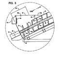
FIG. 3 is an enlarged portion ofFIG. 2 ; -
FIG. 4 is an enlarged portion ofFIG. 2 ; -
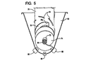
FIG. 5 is a partial cutaway, end elevation view of the first example separator system; -
FIG. 6 is an end perspective view taken along lines 6-6 inFIG. 2 ; -
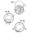
FIGS. 6A and 6B are section views taken alonglines 6A-6A inFIG. 2 illustrating the separation of the raw slurry material into a thinned portion and a thickened portion; -
FIG. 6C is a section view taken alonglines 6C-6C inFIG. 6B ; -
FIG. 6D is a section view similar toFIG. 6C without the raw slurry material; -
FIG. 7 is a cutaway view taken along lines 7-7 inFIG. 2 ; -
FIG. 8 is a perspective view of a second example separator system; -
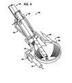
FIG. 9 is a side elevation view of the second example separator system; -
FIG. 10 is a perspective view of a proximal end of a barrel member of the separator member illustrating a portion of the pre-processing member thereof; -
FIG. 11 is an enlarged portion ofFIG. 9 ; -
FIG. 12A is a perspective view of a distal end of a barrel member; -
FIG. 12B is a section view of an intermediate portion of the barrel member; -
FIG. 13 is a perspective view of the distal end of a barrel member of the separator member illustrating portions of the separator members; -
FIG. 14 is a cutaway view taken along lines 14-14inFIG. 9 ; -
FIG. 15 is a section view taken along lines 15-15 inFIG. 10 ; -
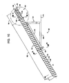
FIG. 16 is a side elevation view of a third example particulate separator system; -
FIG. 16A is a enlarged portion of the third example particulate separator system depicted inFIG. 16 ; -
FIGS. 17 and 18 are section views of a portion of a processing structure of the third example particulate separator system; -
FIG. 19 is a side elevation section view depicting the processing of a raw slurry using the third example particulate separator system; -
FIG. 20 is a side elevation section view of a fourth example particulate separator system; and -
FIG. 21 is a side elevation section view of a fifth example particulate separator system. - Referring initially to
FIG. 1 of the drawing, depicted at 20 therein is a first example separator system constructed in accordance with, and embodying, the principles of the present invention. The first example separator system comprises asupport frame 22, aprocessing system 24, atrough system 26, and adrive system 28. - In general, the
support frame 22 supports theprocessing system 24 relative to thetrough system 26 such that slurry material within thetrough system 26 is fed into theprocessing system 24. Thedrive system 28 rotates at least a portion of theprocessing system 24 such that particulate material such as sand is extracted from the slurry material fed into and through theprocessing system 24. - The
example support frame 22 defines asurface engaging portion 30, asupport portion 32,cradle portions 33, a bearingsurface 36, and amotor platform 38. Thesurface engaging portion 30 defines a reference plane P1, and thesupport portion 32 defines a support plane P2 that extends at an angle to the reference plane P1 (FIG. 2 ). Thesurface engaging portion 30 is adapted to be supported on a support surface such that the reference plane P1 is substantially horizontal. Accordingly, the reference plane P2 extends at an angle with respect to horizontal. - The purpose of the
support frame 22 is to support theprocessing system 24 at a particular angle with respect to horizontal and in a desired position with respect to thetrough system 26. Any structure that supports one or all of the processing, trough, and/ordrive systems example support frame 22. -
FIG. 1 further shows that theexample processing system 24 comprises aprocessing structure 40, afirst processing conduit 42, and asecond processing conduit 44. As perhaps best shown inFIG. 2 , theprocessing structure 40 defines a processing axis A1 and aprocessing chamber 46. Theexample cradle portions 33 are configured to supporttrough system 26. The bearingsurface 36 andmotor platform 38 are arranged and configured such that the processing axis A1 is substantially parallel to the support plane P2 as will be described in further detail below. The processing axis A1 thus extends at an angle with respect to horizontal. - The
example trough system 26 comprises amain trough 50, an inlet conduit 52, and anupper trough 54. Adivider surface 56 separates themain trough 50 from theupper trough 54. Abaffle 58 divides themain trough 50 into aninlet portion 50a and afeed portion 50b. The inlet conduit 52 is arranged to deposit raw slurry material into theinlet portion 50a. Raw slurry material in theinlet portion 50a flows down and under thebaffle 58 before flowing into thefeed portion 50b. - The
example drive system 28 comprises a drive shaft 60 (FIG. 3 ), ashaft bearing assembly 62, atransmission assembly 64, adrive motor assembly 66, and a plurality (two or more) bearing wheel assemblies 68 (FIG. 7 ). Thedrive motor assembly 66 rotates thedrive shaft 60 through thetransmission assembly 64. Theexample drive shaft 60 is connected to theprocessing structure 40 such that rotation of thedrive shaft 60 causes rotation of theprocessing structure 40 about the processing axis A1. Theshaft bearing assembly 62 is arranged to support thedrive shaft 60 and thus an end of theprocessing structure 40. Thebearing wheel assemblies 68 are configured to support a portion of theprocessing structure 40 for rotation about the processing axis A1. - The
example processing structure 40 comprises abarrel member 70, aguide member 72, anauger member 74, a pre-processingmember 76, and a plurality (two or more) ofseparator members 78. Theexample barrel member 70 is an elongate cylinder made of material capable of maintaining this cylindrical shape while supporting theguide member 72,auger member 74, pre-processingmember 76, andseparator members 78 as will be described below. Theexample barrel member 70 is made of steel, but other materials such as plastic or composites may be used under certain circumstances. - The
barrel member 70 defines both theprocessing chamber 46 and the processing axis A1. Theprocessing chamber 46 defines afeed portion 80, apre-processing portion 82, aseparator portion 84, and anoutlet portion 86. - The pre-processing
member 76 andseparator members 78 extend into theprocessing chamber 46 from the interior wall of thebarrel member 70. In particular, the pre-processingmember 76 extends substantially radially inwardly from thebarrel member 70 into part of thefeed portion 80 and throughout thepre-processing portion 82 of theprocessing chamber 46. Theexample pre-processing member 76 follows a predetermined helical path defined by the diameter of thebarrel member 70 and the distance between axially spaced portions of the pre-processingmember 76. In the following discussion, each portion or segment of the pre-processingmember 76 extending through one rotation along the helical path defines a course. These discrete portions or sections of the pre-processingmember 76 may thus be referred to as courses. - The
guide member 72 is rigidly secured to aninner edge 76a of the portion of the pre-processingmember 76 within thefeed portion 80 such that a longitudinal axis of theguide member 72 is aligned with the processing axis A1. Theauger member 74 is rigidly secured to theguide member 72 such that theauger member 74 extends from theguide member 72 outside of theprocessing chamber 46. Theexample auger member 74 further follows substantially the same predetermined helical path as the pre-processingmember 76. Anotch 70a is formed in thebarrel member 70 to create a path from thefeed portion 50b of themain trough 50 into theprocessing chamber 46 around theauger member 74 and through the pre-processingmember 76. - The
separator members 78 extend generally radially inwardly from thebarrel member 70 and generally follow the predetermined helical path defined by the pre-processingmember 76. However, theseparator members 78 are spaced from each other along the predetermined helical path and/or deviate from the predetermined helical path such thatseparator gaps 88 are formed betweenadjacent separator members 78. - In particular, first and second
example separator members FIG. 6D . As generally described above, the processing axis A1 extends at an angle with respect to horizontal; the processing axis A1 thus defines up and down directions as represented by arrows labeled UP and DOWN in drawingFIGS. 1-4 ,6C, and 6D . In the context of any given pair of separator members, the uppermost separator member will be referred to as the as the leading separator member, while the lowermost separator member will be referred to as the trailing separator member. Using similar terminology, each separator member defines to radially aligned edges, and the uppermost of these edges will be referred to as the leading edge, while the lower most of these edges will be referred to as the trailing edge. - Accordingly, the first
example separator member 78a is the leading separator member of this pair of separating members and defines aleading edge 90a and a trailingedge 92a. The secondexample separator member 78b is the trailing separator member in this pair and defines aleading edge 90b and a trailingedge 92b. - Using this terminology,
FIG. 6D shows that theleading edge 90b of the trailingseparator member 78b is above the trailingedge 92a of the leadingseparator member 78a by a distance D1.FIG. 6D also shows that theleading edge 90b of the trailingseparator member 78b is circumferentially spaced from the trailingedge 92a of the leadingseparator member 78a by a distance D2. At least one of these distances D1 and D2 must be greater than zero to define theseparator gap 88. - The
example separator members 78 are in the shape of segments of the predetermined helical path but each helical separator member is offset from the predetermined helical path relative to the helical separators adjacent thereto. Another way of forming theseparator gaps 88 is to arrange non-helical separator members along the predetermined helical path. Additionally, non-helical separator members may be offset from the predetermined helical path to form theseparator gaps 88. - The
example processing structure 40 further comprises cleaningblades 94 formed on the outer surface thereof.Main trough outlets 96 are formed in themain trough 50, whileupper trough outlets 98 are formed in theupper trough 54. - The first
example separator system 20 operates as follows. Raw slurry material is forced through the inlet conduit 52 into theinlet portion 50a of themain trough 50. Theexample separator system 20 is designed to process raw slurry material a liquid portion comprising at least rinse liquid, such as water, and manure and a particulate portion comprising particulate material such as sand. - The
baffle 58 forces the raw slurry material to flow down to the bottom of themain trough 50 before entering thefeed portion 50b of thattrough 50. Themain trough 50 thus functions like a gravity separator in which heavier particulate material such as sand sinks to the bottom and the liquid portion rises to the top. The flow path under thebaffle 58 forces particulate material to flow to a lower portion of thetrough 50 before entering theupper trough 54 as will be described in further detail below. - The
support frame 22 supports theprocessing structure 40 such that thefeed portion 80 of theprocessing chamber 46 is within thefeed portion 50b of themain trough 50. Theauger member 74 extends into the bottom of themain trough 50 with thedrive shaft 60 partly within theguide member 72. In particular, thedrive shaft 60 is coupled to theguide member 72 such that axial rotation of thedrive shaft 60 rotates theguide member 72 about the processing axis A1. And because theguide member 72 supports theauger member 74 and pre-processingmember 76, theauger member 74 and pre-processingmember 76 also rotate about the processing axis A1. Similarly, the pre-processingmember 76 supports thebarrel member 70, so thebarrel member 70 also rotates about the processing axis A1. And axial rotation of thebarrel member 70 causes theseparator members 78 also to rotate about the processing axis A1. - As the
auger member 74 rotates about the processing axis A1, a leading surface of theauger member 74 acts on the raw slurry material within themain trough 50 to displace this raw slurry material up towards the processingchamber 46. At about thenotch 70a formed in thebarrel member 70, the raw slurry material displaced by theauger member 74 enters thepre-processing portion 82 of the processing chamber, where the raw slurry material is displaced through thepre-processing portion 82 by a leading surface of the pre-processingmember 76. - As the pre-processing member displaces the raw slurry material up along the processing axis A1 through the pre-processing portion of the processing chamber, the particulate portion of the raw slurry material sinks in the liquid portion of the raw slurry material, separating the raw slurry material into thickened portion and a thinned portion. The thickened portion is relatively close to the inner wall of the
barrel member 70, while the thinned portion is away from this inner wall. The thickened portion has a relatively high concentration of particulate material, while the thinned portion has a relatively lower concentration of the particulate material. The concentration of particulate material in the thickened portion increases as the raw slurry material proceeds up through thepre-processing portion 82 of theprocessing chamber 46. - Towards the lower end of the
pre-processing portion 82 of theprocessing chamber 46, the thinned portion of the raw slurry material flows over theinner edge 76a of the pre-processingmember 76 from one course of the pre-processingmember 76 back down to the course below. This process begins to concentrate the particulate material within the thickened portion. At some point along thepre-processing portion 82, the thinned portion of the raw slurry material no longer flows over theinner edge 76a. - After this point, the slurry material continues to separate, with the lighter, leading portion thereof being pushed in front (i.e., in the direction opposite the direction of rotation of the barrel member) and the heavier lagging portion behind (i.e., in the direction of rotation of the barrel member).
- Accordingly, by the time the raw slurry material reaches the
separator portion 84, the slurry material has been thickened and separated into a leading portion and a lagging portion. The leading portion will contain a lower concentration of particulate, while the lagging portion will contain a higher concentration of particulate. -
FIGS. 6A, 6B , and6C illustrate what happens as the slurry passes through theseparator portion 84 of theprocessing chamber 46.FIGS. 6A and6C show the leadingportion 99a of the slurry material, whileFIGS. 6A, 6B , and6C show both the leadingportion 99a and the laggingportion 99b. As generally described above, rotation of thebarrel member 70 causes the leadingportion 99a to cross theseparator gaps 88. The more fluid leadingportion 99a passes through thegaps 88 to the course below. The less fluid laggingportion 99b, however, projects across the separator gap onto thenext separator member 78. Accordingly, as the slurry material moves across thesuccessive separator gaps 88 formed by theseparator members 78 in the separator region, more and more of the more fluid portion flows back down through the processing chamber. Theprocessing system 24 thus separates the particulate portion of the raw slurry material from the liquid portion of the raw slurry material. - The portion of the material raw slurry material that reaches the
outlet portion 86 of the separator chamber comprises a very high proportion of the particulate portion in comparison to the proportion of the particulate material in the raw slurry material entering thefeed portion 80. - In addition to separating the particulate portion from the liquid portion of the raw slurry material, the first example
sand separating system 20 may be configured to clean the particulate portion and/or dilute the liquid portion. In particular, one or both of the first and second example processing conduits of the firstexample processing system 24 may be configured to arrange rinse liquids within theprocessing chamber 46. - In the
example processing system 24, thefirst processing conduit 42 is arranged to deposit a first rinse fluid at a first location 42a within theprocessing chamber 46. Thesecond processing conduit 44 is arranged to deposit a second rinse fluid at asecond location 44a within theprocessing chamber 46. Theprocessing system 24 may thus be operated without a supplemental rinse fluid, with either the first rinse fluid or the second rinse fluid, or with both the first and second rinse fluids. - Typically, the first location 42a at which the first rinse fluid is introduced is below the
second location 44a at which the second rinse fluid. In theexample processing system 24, the first location 42a is between thesecond location 44a and thefeed portion 80, approximately at the junction of thepre-processing portion 82 and theseparator portion 84. The second location is between the first location 42a and theoutlet portion 86 of theprocessing chamber 46. - In this configuration, the second rinse fluid may be a relatively pure or clean liquid such as water while the first rinse fluid may be a relatively impure fluid that is a byproduct of the stall rinse system. The first rinse fluid will provide a fresh volume of low contaminant liquid material to facilitate separation of the particulate portion from the liquid portion of the raw slurry material. The second rinse fluid will provide a fresh volume of uncontaminated liquid material to rinse contaminants from the particulate portion of the raw slurry material. Additives such as lubricants, defoamers, disinfectants, or the like may be added to one or both of the first and second rinse fluids.
- The liquid portion of the raw slurry material flows back down through the
processing chamber 46 and collects in thefeed portion 50b of themain trough 50. This liquid portion will collect in the upper portion of themain trough 50 and will eventually flow over thedivider surface 56, intoupper trough 54, and out of thesystem 20 through theupper trough outlets 98. Themain trough outlets 96 allow material to be removed from the bottom of themain trough 50 when necessary. - Referring now to
FIGS. 9-14 of the drawing, depicted at 120 therein is a second example separator system constructed in accordance with, and embodying, the principles of the present invention. The second example separator system comprises asupport frame 122, aprocessing system 124, atrough system 126, and adrive system 128. - In general, the
support frame 122 supports the processing system relative to thetrough system 126 such that slurry material within thetrough system 126 is fed into theprocessing system 124. Thedrive system 128 rotates at least a portion of theprocessing system 124 such that particulate material such as sand is extracted from the slurry material fed into and through theprocessing system 124. - The
example support frame 122 defines asurface engaging portion 130, asupport portion 132, a bearingsurface 134, amotor platform 136, and braceassembly 138. Thesurface engaging portion 130 defines a reference plane P1, and thesupport portion 132 defines a support plane P2 that extends at an angle to the reference plane P1 (FIG. 12 ). Thesurface engaging portion 130 is adapted to be supported on a support surface such that the reference plane P1 is substantially horizontal. Accordingly, the reference plane P2 extends at an angle with respect to horizontal. - The purpose of the
support frame 122 is to support theprocessing system 124 at a particular angle with respect to horizontal and in a desired position with respect to thetrough system 126. -
FIG. 8 further shows that theexample processing system 124 comprises aprocessing structure 140, afirst processing conduit 142, and asecond processing conduit 144. As perhaps best shown inFIG. 12 , theprocessing structure 140 defines a processing axis A1 and aprocessing chamber 146. The bearingsurface 134 andmotor platform 136 are arranged and configured such that the processing axis A1 is substantially parallel to the support plane P2 as will be described in further detail below. The processing axis A1 thus extends at an angle with respect to horizontal. - The
example trough system 126 comprises amain trough 150, aninlet conduit 152, and anupper trough 154. Adivider surface 156 separates themain trough 150 from theupper trough 154. Theinlet conduit 152 is arranged to deposit raw slurry material into themain trough 150. Anoutlet conduit 158 allows fluid to flow out of theupper trough 154. - The
example drive system 128 comprises adrive motor 160, adrive member 162 such as a belt or chain, adrive surface 164 such as a sprocket, andbearing wheel assemblies 166. Thedrive motor 160 causes rotation of theprocessing structure 140 through thedrive member 162 and thedrive surface 164. Thebearing wheel assemblies 166 support theprocessing structure 140 for rotation about the processing axis A1. - The
example processing structure 140 comprises abarrel member 170, apre-processing member 172, a plurality (two or more) ofseparator members 174, aninlet member 176, and anextension portion 178. Theexample barrel member 170 is an elongate cylinder made of material capable of maintaining this cylindrical shape while supporting thepre-processing member 172 andseparator members 174 as will be described below. Theexample barrel member 170 is made of steel, but other materials such as plastic or composites may be used under certain circumstances. - The
barrel member 170 defines both theprocessing chamber 146 and the processing axis A1. Theprocessing chamber 146 defines afeed portion 180, apre-processing portion 182, aseparator portion 184, and anoutlet portion 186. Part of thepre-processing member 172 extends out of theprocessing chamber 146 and to define the feed portion of theprocessing chamber 146. Theinlet member 176 is arranged adjacent to the feed portion of theprocessing chamber 146 and defines an inlet surface that facilitates the entry of the raw slurry material into theprocessing chamber 146. Part of thelast separator member 174 extends out through theoutlet opening 186 such that particulate material does not drop back into theseparator portion 184 of theprocessing chamber 146. - The
pre-processing member 172 andseparator members 174 extend into theprocessing chamber 146 from the interior wall of thebarrel member 170. In particular, the pre-processingmember 172 extends substantially radially inwardly from thebarrel member 170 into part of thefeed portion 180 and throughout thepre-processing portion 182 of theprocessing chamber 146. Theexample pre-processing member 172 follows a predetermined helical path defined by the diameter of thebarrel member 170 and the distance between axially spaced portions of thepre-processing member 172. In the following discussion, each portion or segment of thepre-processing member 172 extending through one rotation along the helical path defines a course. These discrete portions or sections of thepre-processing member 172 may thus be referred to as courses. - The
separator members 174 extend generally radially inwardly from thebarrel member 170 and generally follow the predetermined helical path defined by thepre-processing member 172. However, theseparator members 174 are spaced from each other along the predetermined helical path and/or deviate from the predetermined helical path such thatseparator gaps 188 are formed betweenadjacent separator members 174. - The
example processing structure 140 further comprises cleaning blades 190 formed on the outer surface thereof. In addition, as shown inFIG. 12B ,openings 192 are formed in theprocessing structure 140. Theopenings 192 are arranged betweendownstream surface portions 174a andupstream surface portions 174b of theseparator members 174. For reasons that will become apparent from the following discussion, theopenings 192 are arranged immediately adjacent to thedownstream surface portion 174a and are spaced a distance from theupstream surface portions 174b. - The second
example separator system 120 operates in a manner that is generally similar to that of thefirst example separator 20 described above. Raw slurry material is forced through theinlet conduit 152 into themain trough 150. Theexample separator system 120 is designed to process raw slurry material a liquid portion comprising at least rinse liquid, such as water, and manure and a particulate portion comprising particulate material such as sand. Themain trough 150 functions like a gravity separator in which heavier particulate material such as sand sinks to the bottom and the liquid portion rises to the top. - The
support frame 122 supports theprocessing structure 140 such that thefeed portion 180 of theprocessing chamber 146 is within themain trough 150. Rotation of thebarrel member 170 causes the particulate portion of the raw slurry material to move up through theprocessing chamber 146 and out of theoutlet portion 186. As generally described above, the portion of the material raw slurry material that reaches theoutlet portion 186 of the separator chamber comprises a very high proportion of the particulate portion in comparison to the proportion of the particulate material in the raw slurry material entering thefeed portion 180. - In addition to separating the particulate portion from the liquid portion of the raw slurry material, the second example
sand separating system 120 may be configured to clean the particulate portion and/or dilute the liquid portion. In particular, one or both of the first and second example processing conduits of the secondexample processing system 124 may be configured to arrange rinse liquids within theprocessing chamber 146. - In the
example processing system 124, thefirst processing conduit 142 is arranged to deposit a first rinse fluid at afirst location 142a within theprocessing chamber 146. Thesecond processing conduit 144 is arranged to deposit a second rinse fluid at asecond location 144a within theprocessing chamber 146. Theprocessing system 124 may thus be operated without a supplemental rinse fluid, with either the first rinse fluid or the second rinse fluid, or with both the first and second rinse fluids. - Typically, the
first location 142a at which the first rinse fluid is introduced is below thesecond location 144a at which the second rinse fluid. In theexample processing system 124, thefirst location 142a is between thesecond location 144a and thefeed portion 180, approximately at the junction of thepre-processing portion 182 and theseparator portion 184. The second location is between thefirst location 142a and theoutlet portion 186 of theprocessing chamber 146. - In this configuration, the second rinse fluid may be a relatively pure or clean liquid such as water while the first rinse fluid may be a relatively impure fluid that is a byproduct of the stall rinse system. The first rinse fluid will provide a fresh volume of low contaminant liquid material to facilitate separation of the particulate portion from the liquid portion of the raw slurry material. The second rinse fluid will provide a fresh volume of uncontaminated liquid material to rinse contaminants from the particulate portion of the raw slurry material. Additives such as lubricants, defoamers, disinfectants, or the like may be added to one or both of the first and second rinse fluids.
- The liquid portion of the raw slurry material flows back down through the
processing chamber 146 and collects in themain trough 150. This liquid portion will collect in the upper portion of themain trough 150 and will eventually flow over thedivider surface 156, intoupper trough 154, and out of thesystem 120 through theupper trough outlet 158. - As shown in
FIG. 12B , theopenings 192 formed in theprocessing structure 140 are configured to allow a portion of the material supported against theupstream surface portions 174b to flow out of theprocessing chamber 146. The purpose of theseopenings 192 is to allow certain solid particulate materials such as corn in the liquid portion of the raw slurry flowing back down through theprocessing chamber 146 to be removed therefrom. - Referring now to
FIG. 15 of the drawing, depicted at 220 therein is a second example separator system constructed in accordance with, and embodying, the principles of the present invention. The second example separator system comprises asupport frame 222, aprocessing system 224, atrough system 226, and adrive system 228. Theprocessing system 224 anddrive system 228 are or may be the same as theprocessing system 124 anddrive system 128 described above and will not be described herein in detail. - The
example trough system 226 comprises amain trough 250, aninlet conduit 252, and anupper trough 254. Adivider surface 256 separates themain trough 250 from theupper trough 254. Theinlet conduit 252 is arranged to deposit raw slurry material into themain trough 250. Anoutlet conduit 258 allows fluid to flow out of theupper trough 254. In theexample trough system 226, theinlet conduit 252 is arranged such that themain trough 250 is gravity fed. Raw slurry material entering the main trough flows down and around a conical surface defined by themain trough 250 so that the particulate material has time to sink to the bottom of themain trough 250 and be taken in by theprocessing system 224. - Referring now to
FIGS. 16-18 of the drawing, depicted at 320 therein is a third example particulate separator system constructed in accordance with, and embodying, the principles of the present invention. One problem with a separator system such as theseparator system 20 described above is that lighter particulate materials contained within the raw slurry material are not effectively removed and can clog the feed portion of the processing chamber. One such solid material is corn. Corn is commonly used as an animal feed, and a typical raw slurry material generated by a dairy operation will contain a certain percentage of corn. Corn kernels are too light to be separated using theseparator system 20 as described above and tend to flow back towards the intake portion. Eventually, enough of these lighter particulate materials accumulate in themain trough 50 that function of thesystem 20 is compromised. The fourth example particulate separator system is designed to reduce accumulation of lighter particulate materials in the main trough. - As shown in
FIG. 16 , the thirdexample separator system 320 comprises asupport frame 322, aprocessing system 324, atrough system 326, and adrive system 328. The thirdexample separator system 320 is similar to the first exampleparticulate separator system 20 described above and will be described primarily to the extent that it differs from the firstexample separator system 20 described above. -
FIG. 16 further shows that theexample processing system 324 comprises aprocessing structure 330 and aprocessing conduit 332. Operation of theexample drive system 328 causes rotation of theprocessing structure 330 about a processing axis. Theexample trough system 326 comprises amain trough 340 and adrain conduit 342. Abaffle 344 and awall 346 are formed in thetrough system 326. - The
example processing structure 330 comprises abarrel member 350, aguide member 352, anauger member 354, apre-processing member 356, and a plurality (two or more) ofseparator members 358. Theexample barrel member 350 is an elongate cylinder made of material capable of maintaining this cylindrical shape while supporting theguide member 352,auger member 354,pre-processing member 356, andseparator members 358. Thebarrel member 350 defines both themain processing chamber 336 and a processing axis. Themain processing chamber 336 defines afeed portion 360, apre-processing portion 362, aseparator portion 364, anoutlet portion 366, and asecondary processing portion 368 within thepre-processing portion 362. - The
pre-processing member 356 andseparator members 358 extend generally inwardly radially into themain processing chamber 336 from the interior wall of thebarrel member 350. Theseparator members 358 extend generally radially inwardly from thebarrel member 350 and generally follow the predetermined helical path defined by thepre-processing member 356. However, theseparator members 358 are spaced from each other along the predetermined helical path and/or deviate from the predetermined helical path such thatseparator gaps 370 are formed betweenadjacent separator members 358. - The first
example separator system 320 operates as follows. Raw slurry material is introduced into an inlet portion of themain trough 340. Theexample separator system 320 is designed to process raw slurry material comprising a liquid portion comprising at least rinse liquid such as water, manure, a heavier particulate portion comprising particulate material such as sand, and a lighter particulate portion comprising a particulate material such as feed corn. - The
baffle 344 forces the raw slurry material to flow down to the bottom of themain trough 340 before entering a feed portion of thattrough 340. Themain trough 340 thus functions like a gravity separator in which heavier particulate material such as sand sinks to the bottom and the liquid portion rises to the top. - The
support frame 322 supports theprocessing structure 330 at an angle such that thefeed portion 360 of themain processing chamber 336 is within the feed portion of themain trough 340 and theoutlet portion 366 extends into the air away from themain trough 340. Theauger member 354 extends into the bottom of themain trough 340. - As the
auger member 354 rotates about the processing axis, a leading surface of theauger member 354 acts on the raw slurry material within themain trough 340 to displace this raw slurry material up towards themain processing chamber 336. At about thenotch 350a formed in thebarrel member 350, the raw slurry material displaced by theauger member 354 enters thepre-processing portion 362 of the processing chamber, where the raw slurry material is displaced through thepre-processing portion 362 by a leading surface of thepre-processing member 356. - The
pre-processing member 356 displaces the raw slurry material up along the processing axis through thepre-processing portion 362 of themain processing chamber 336. As the slurry material is displaced upwardly along the processing axis, the particulate portion of the raw slurry material sinks in the liquid portion of the raw slurry material, separating the raw slurry material into thickened portion and a thinned portion. The thickened portion is relatively close to the inner wall of thebarrel member 350, while the thinned portion is away from this inner wall. The thickened portion has a relatively high concentration of heavier particulate material, while the thinned portion has a relatively lower concentration of the heavier particulate material. The concentration of heavier particulate material in the thickened portion increases as the raw slurry material proceeds up through thepre-processing portion 362 of themain processing chamber 336. However, the thinned portion contains a relatively higher percentage of the lighter particulate materials in the raw slurry material. - Towards the lower end of the
pre-processing portion 362 of themain processing chamber 336, the thinned portion of the raw slurry material flows over theinner edge 356a of thepre-processing member 356 from one course of thepre-processing member 356 back down to the course below. This process rinses impurities from the raw slurry material and begins to concentrate the heavier particulate material within the thickened portion. At some point towards the upper end of thepre-processing portion 362, the thinned portion of the raw slurry material no longer flows over theinner edge 356a. On the other hand, this process tends to concentrate the lighter particulate material within the thinned portion, and the thinned portion carries the lighter particulate material downward through themain processing chamber 336. - In the
separator portion 364 above thepre-processing portion 362, the slurry material continues to separate, with the lighter, leading portion thereof being pushed in front (i.e., in the direction opposite the direction of rotation of the barrel member) and the heavier lagging portion behind (i.e., in the direction of rotation of the barrel member). - Accordingly, by the time the raw slurry material reaches the
separator portion 364, the thickened portion of the slurry material has separated into a thinner leading portion a relatively lower concentration of heavier particulate material and a thicker lagging portion comprising a relatively higher concentration of heavier particulate material. And, although much lighter particulate material has been removed at this point, the leading portion will likely contain a higher concentration of any remaining lighter particulate material, while the lagging portion will likely contain a lower concentration of the lighter particulate material. The leading portion of the thickened raw slurry material within the separator portion falls through theseparator gaps 370, while the lagging portion is passed from oneseparator member 358 over theseparator gaps 370. - As shown in
FIGS. 16-19 , the thirdexample separator system 320 comprises asecondary processing member 380 arranged immediately behind at least a portion of thepre-processing member 356 in thesecondary processing portion 368 of themain processing chamber 336. The examplesecondary processing member 380 is shaped like thepre-processing member 356 and, like thepre-processing member 356, is secured to the interior wall of thebarrel member 350.End plates barrel member 350 such that theseplates pre-processing member 356 and the ends of thesecondary processing member 380. - The
pre-processing member 356, thesecondary processing member 380, and theend plates secondary processing chamber 386 within themain processing chamber 336. The examplesecondary processing chamber 386 defines a shallow, helical trough with an open side facing radially inwardly. This trough extends around at least one, and preferably at least one and one-quarter, revolutions or courses of thepre-processing member 356. One or moresecondary processing openings 388 are formed in thebarrel member 350 within thesecondary processing chamber 386 adjacent to a portion of thepre-processing member 356. In the following discussion, the portion of thepre-processing member 356 adjacent to the one or moresecondary openings 388 will be referred to as afirst portion 356a of thepre-processing member 356, while the portion of thepre-processing member 356 adjacent to thesecondary processing member 380 will be referred to as a second portion 356b of thepre-processing member 356. - The purpose of the
secondary processing chamber 386 and thesecondary processing openings 388 is to alleviate the clogging caused by light particulate materials such as corn. As perhaps best shown inFIG. 19 , rotation of thebarrel member 350 causes the raw slurry material to be displaced upward along themain processing chamber 336. However, theend plates pre-processing member 356 from entering thesecondary processing chamber 386. The raw slurry material carried by the pre-processing material thus bypasses thesecondary processing chamber 386 on the way up through theprocessing chamber 336. - However, as the raw slurry material passes around the
secondary processing chamber 386 while traveling up through themain processing chamber 336, the raw slurry material mixes with rinse liquids introduced into theseparator portion 364 of themain processing chamber 336 by theprocessing conduit 332. The raw slurry material and rinse liquids are mixed and allow separation of the heavier particulate materials from the liquid materials as generally described above with reference to the firstexample separator system 20. - Above the
secondary processing chamber 386, the lighter particulate materials will float to the top of the mixture of raw slurry material and rinse liquids. The lighter particulate materials will thus flow down through themain processing chamber 336 by flowing or spilling over theinner edge 356a of thepre-processing member 356 with the liquid portion of the raw slurry material and the rinse liquids. - Thus, the liquid portion of the raw slurry material, rinse liquids, and these lighter particulate materials will flow or spill over the inner edge of the
pre-processing member 356 and into thesecondary processing chamber 386. However, the heavier particulate materials, such as sand, sink to the bottom of the slurry and rinse liquids being displaced or carried upwards by thepre-processing member 356 and thus do not flow over theinner edge 356a and into thesecondary processing chamber 386. As thebarrel member 350 rotates, the slurry liquids, rinse liquids, and lighter particulate materials eventually flow out of thepre-processing member 356, through the shallow trough formed by thesecondary processing chamber 386, and then through thesecondary processing openings 388. At least one and preferably two to three of thesecondary processing openings 388 are formed to allow the material collected by thesecondary processing chamber 386 to flow out of these openings as thebarrel member 350 rotates. - The
drain conduit 342 is arranged below thesecondary processing openings 388. Accordingly, any materials flowing out of thesecondary processing openings 388 fall into thedrain conduit 342 and may be reused, recycled, or disposed of. Thewall 346 prevents materials flowing into thedrain conduit 342 from flowing into themain trough 340. Materials collected by thesecondary processing chamber 386 are thus prevented from reaching the feed portion of themain trough 340. Much of the light particulate in the raw slurry material is collected by the secondary processing chambers and is thus prevented from collecting in and clogging themain trough 340. - Referring now to
FIG. 20 of the drawing, depicted at 420 therein is a fourth example separator system constructed in accordance with, and embodying, the principles of the present invention. The fourthexample separator system 420 comprises a support frame 422, aprocessing system 424, atrough system 426, and a drive system (not shown). The fourthexample separator system 420 is similar to the secondexample separator system 120 described above and will be described herein primarily to the extent that thesystem 420 differs from the previously describedsystem 120. - The purpose of the support frame 422 is to support the
processing system 424 at a particular angle with respect to horizontal and in a desired position with respect to thetrough system 426.FIG. 20 further shows that theexample processing system 424 comprises aprocessing structure 430 and aprocessing conduit 432. Theprocessing structure 430 defines a processing axis and amain processing chamber 434. Theexample trough system 426 comprises amain trough 440 and asecondary trough 442. - The
example processing structure 430 comprises abarrel member 450, apre-processing member 452, a plurality (two or more) ofseparator members 454, aninlet member 456, and anextension portion 458. Theexample barrel member 450 is an elongate cylinder made of material capable of maintaining this cylindrical shape while supporting thepre-processing member 452 andseparator members 454 as will be described below. Theexample barrel member 450 is made of steel, but other materials such as plastic or composites may be used under certain circumstances. - The
barrel member 450 defines both themain processing chamber 434 and the processing axis. Themain processing chamber 434 defines afeed portion 470, apre-processing portion 472, aseparator portion 474, anoutlet portion 476, and a lowersecondary processing portion 478. Part of thepre-processing member 452 extends out of themain processing chamber 434 to define the feed portion of themain processing chamber 434. Theinlet member 456 is arranged adjacent to the feed portion of themain processing chamber 434 and defines an inlet surface that facilitates the entry of the raw slurry material into themain processing chamber 434. Part of thelast separator member 454 extends out through theoutlet opening 476 such that particulate material does not drop back into theseparator portion 474 of themain processing chamber 434. - The
pre-processing member 452 andseparator members 454 extend into themain processing chamber 434 from the interior wall of thebarrel member 450. In particular, the pre-processingmember 452 extends substantially radially inwardly from thebarrel member 450 into part of thefeed portion 470 and throughout thepre-processing portion 472 of themain processing chamber 434. Theexample pre-processing member 452 follows a predetermined helical path defined by the diameter of thebarrel member 450 and the distance between axially spaced portions of thepre-processing member 452. In the following discussion, each portion or segment of thepre-processing member 452 extending through one rotation along the helical path defines a course. These discrete portions or sections of thepre-processing member 452 may thus be referred to as courses. - The
separator members 454 extend generally radially inwardly from thebarrel member 450 and generally follow the predetermined helical path defined by thepre-processing member 452. However, theseparator members 454 are spaced from each other along the predetermined helical path and/or deviate from the predetermined helical path such thatseparator gaps 460 are formed betweenadjacent separator members 454. -
FIG. 20 further shows that the fourthexample separator system 420 comprises asecondary processing member 480 arranged immediately behind at least a portion of thepre-processing member 452 in thesecondary processing portion 478 of themain processing chamber 434. The examplesecondary processing member 480 is shaped like thepre-processing member 452 and, like thepre-processing member 452, is secured to the interior wall of thebarrel member 450. Afirst end plates 482 and a second end plate (not shown) are further secured to the interior wall of thebarrel member 450 such that these plates extend between thepre-processing member 452 and the ends of thesecondary processing member 480. - The
pre-processing member 452, thesecondary processing member 480, and the end plates thus define asecondary processing chamber 486 within themain processing chamber 434. The examplesecondary processing chamber 486 defines a shallow, helical trough with an open side facing radially inwardly. This trough extends around at least one, and preferably at least one and one-quarter, revolutions or courses of thepre-processing member 452. Additionally, one or moresecondary processing openings 488 are formed in thebarrel member 450 within thesecondary processing chamber 486. The purpose of thesecondary processing chamber 486 and thesecondary processing openings 488 is to alleviate the clogging caused by light particulate materials such as corn. - As with the
system 320 described above, rotation of thebarrel member 450 causes the raw slurry material to be displaced upward along themain processing chamber 434. However, the end plates prevent the raw slurry material carried upward by thepre-processing member 452 from entering the processing chambers. The raw slurry material carried by the pre-processing material thus bypasses the secondary processing chambers on the way up through themain processing chamber 434. - However, as the raw slurry material passes around the secondary processing chambers while traveling up through the
main processing chamber 434, the raw slurry material mixes with rinse liquids introduced into theseparator portion 474 of themain processing chamber 434 by theprocessing conduit 432. The raw slurry material and rinse liquids are mixed and allow separation of the heavier particulate materials from the liquid materials as generally described above with reference to the firstexample separator system 20. - Above the secondary processing chambers, the lighter particulate materials will float to the top of the mixture of raw slurry material and rinse liquids. The lighter particulate materials will thus flow down through the
main processing chamber 434 over theinner edge 452a of thepre-processing member 452 with the liquid portion of the raw slurry material and the rinse liquids. - Thus, the liquid portion of the raw slurry material, rinse liquids, and these lighter particulate materials will flow over the inner edge of the
pre-processing member 452 and into thesecondary processing chamber 486. However, the heavier particulate materials, such as sand, do not flow over theinner edge 452a into the secondary processing chamber. As thebarrel member 450 rotates, the slurry liquids, rinse liquids, and lighter particulate materials eventually flow out of the proc-processingmember 452 through thesecondary processing openings 488. At least one and preferably two to three of thesecondary processing openings 488 are formed in each of the secondary processing chambers. - The
secondary trough 442 is arranged below thesecondary processing openings 488 of thesecondary processing chamber 486. Accordingly, any materials flowing out of thesecondary processing openings 488 are collected by thetrough 442 for reuse, recycling, or disposal. Materials collected by the secondary processing chambers are thus prevented from reaching themain chamber 440. Much of the light particulate in the raw slurry material is collected by the secondary processing chambers and is thus prevented from collecting in and clogging themain chamber 440. - Referring now to
FIG. 21 of the drawing, depicted at 520 therein is a fifth example separator system constructed in accordance with, and embodying, the principles of the present invention. The fifthexample separator system 520 comprises asupport frame 522, aprocessing system 524, atrough system 526, and a drive system (not shown). The fifthexample separator system 520 is similar to the secondexample separator system 420 described above and will be described herein primarily to the extent that thesystem 520 differs from the previously describedsystems 420. - The purpose of the
support frame 522 is to support theprocessing system 524 at a particular angle with respect to horizontal and in a desired position with respect to thetrough system 526.FIG. 21 further shows that theexample processing system 524 comprises aprocessing structure 530 and aprocessing conduit 532. Theprocessing structure 530 defines a processing axis and amain processing chamber 534. Theexample trough system 526 comprises amain trough 540, a lowersecondary trough 542, and an uppersecondary trough 544. - The
example processing structure 530 comprises abarrel member 550, apre-processing member 552, a plurality (two or more) ofseparator members 554, aninlet member 556, and anextension portion 558. Theexample barrel member 550 is an elongate cylinder made of material capable of maintaining this cylindrical shape while supporting thepre-processing member 552 andseparator members 554 as will be described below. Theexample barrel member 550 is made of steel, but other materials such as plastic or composites may be used under certain circumstances. - The
barrel member 550 defines both themain processing chamber 534 and the processing axis. Themain processing chamber 534 defines afeed portion 570, apre-processing portion 572, aseparator portion 574, anoutlet portion 576, and a lowersecondary processing portion 578a, and an uppersecondary processing portion 578b. Part of thepre-processing member 552 extends out of themain processing chamber 534 and to define the feed portion of themain processing chamber 534. Theinlet member 556 is arranged adjacent to the feed portion of themain processing chamber 534 and defines an inlet surface that facilitates the entry of the raw slurry material into themain processing chamber 534. Part of thelast separator member 554 extends out through theoutlet opening 576 such that particulate material does not drop back into theseparator portion 574 of themain processing chamber 534. - The
pre-processing member 552 andseparator members 554 extend into themain processing chamber 534 from the interior wall of thebarrel member 550. In particular, the pre-processingmember 552 extends substantially radially inwardly from thebarrel member 550 into part of thefeed portion 570 and throughout thepre-processing portion 572 of themain processing chamber 534. Theexample pre-processing member 552 follows a predetermined helical path defined by the diameter of thebarrel member 550 and the distance between axially spaced portions of thepre-processing member 552. In the following discussion, each portion or segment of thepre-processing member 552 extending through one rotation along the helical path defines a course. These discrete portions or sections of thepre-processing member 552 may thus be referred to as courses. - The
separator members 554 extend generally radially inwardly from thebarrel member 550 and generally follow the predetermined helical path defined by thepre-processing member 552. However, theseparator members 554 are spaced from each other along the predetermined helical path and/or deviate from the predetermined helical path such thatseparator gaps 560 are formed betweenadjacent separator members 554. -
FIG. 21 further shows that the fifthexample separator system 520 comprises a lowersecondary processing member 580a and an uppersecondary processing member 580b arranged immediately behind at least a portion of thepre-processing member 552 in the lower and uppersecondary processing portions main processing chamber 534, respectively. The examplesecondary processing members pre-processing member 552 and, like thepre-processing member 552, are secured to the interior wall of thebarrel member 550.First end plates 582a and 582b and second end plates (not shown) are further secured to the interior wall of thebarrel member 550 such that these plates extend between thepre-processing member 552 and the ends of each of thesecondary processing members - The
pre-processing member 552, thesecondary processing members secondary processing chambers main processing chamber 534. The example secondary processing chambers 576a and 576b each define shallow, helical troughs with an open side facing radially inwardly. These troughs extend around at least one, and preferably at least one and one-quarter, revolutions or courses of thepre-processing member 552. Additionally, one or moresecondary processing openings 588 are formed in thebarrel member 550 within each of thesecondary processing chambers secondary processing chambers secondary processing openings 588 is to alleviate the clogging caused by light particulate materials such as corn. - As with the
system 420 described above, rotation of thebarrel member 550 causes the raw slurry material to be displaced upward along themain processing chamber 534. However, the end plates prevent the raw slurry material carried upward by thepre-processing member 552 from entering the processing chambers. The raw slurry material carried by the pre-processing material thus bypasses the secondary processing chambers on the way up through themain processing chamber 534. - However, as the raw slurry material passes around the secondary processing chambers while traveling up through the
main processing chamber 534, the raw slurry material mixes with rinse liquids introduced into theseparator portion 574 of themain processing chamber 534 by theprocessing conduit 532. The raw slurry material and rinse liquids are mixed and allow separation of the heavier particulate materials from the liquid materials as generally described above with reference to the firstexample separator system 20. - Above the secondary processing chambers, the lighter particulate materials will float to the top of the mixture of raw slurry material and rinse liquids. The lighter particulate materials will thus flow down through the
main processing chamber 534 over theinner edge 552a of thepre-processing member 552 with the liquid portion of the raw slurry material and the rinse liquids. - Thus, the liquid portion of the raw slurry material, rinse liquids, and these lighter particulate materials will flow over the inner edge of the
pre-processing member 552 and into thesecondary processing chambers inner edge 552a into the secondary processing chamber. As thebarrel member 550 rotates, the slurry liquids, rinse liquids, and lighter particulate materials eventually flow out of the proc-processingmember 552 through thesecondary processing openings 588. At least one and preferably two to three of thesecondary processing openings 588 are formed in each of the secondary processing chambers. - The
secondary troughs secondary processing openings 588 of the lower and uppersecondary processing chambers secondary processing openings 588 are collected by thetroughs main chamber 540. Much of the light particulate in the raw slurry material is collected by the secondary processing chambers and is thus prevented from collecting in and clogging themain chamber 540.
Claims (18)
- A processing system for processing raw slurry material comprising light particulate material, heavy particulate material, and liquid material to separate the light and heavy particulate materials from the liquid material, the processing system comprising:a barrel member defining a processing axis a feed portion, a processing chamber, and an outlet opening;at least one pre-processing member, where the at least one pre-processing member is supported by the barrel member within the processing chamber;at least one pre-processing opening formed in the barrel member adjacent to a first portion of the pre-processing member; whereinas the barrel member rotates about the processing axis, the at least
one pre-processing member transports at least a portion of the raw slurry material from the feed portion towards the outlet opening such that
at least some of the heavy particulate material in the raw slurry material is transported to the outlet opening,
at least some of the liquid material in the raw slurry material is allowed to flow back towards the feed portion,
at least some of the liquid material and at least some of the light particulate material is allowed to flow through the at least one pre-processing opening in the barrel member. - A processing system as recited in claim 1, wherein: the barrel member defines a pre-processing portion, and a separator portion;
the at least one pre-processing member is supported by the barrel member within the feed portion and the pre-processing portion of the processing chamber;
the processing system further comprises a plurality of separator members, where
the plurality of separator members are supported by the barrel member within the separator portion of the processing chamber, and
the plurality of separator members define at least one separator gap; and
as the barrel member rotates about the processing axis,
the at least one pre-processing member transports at least a portion of the raw slurry material from the feed portion to the separator portion through the pre-processing portion such that
at least some of the particulate material in the raw slurry material is transported to the separator portion,
at least some of the liquid material in the raw slurry material is allowed to flow back towards the feed portion, and
at least some of the liquid material flowing back towards the feed portion and at least some of the light particulate material is allowed to flow through the at least one pre-processing opening in the barrel member;
the plurality of separator members transport at least a portion of the raw slurry material from the pre-processing portion to the outlet opening through the separator portion such that
at least some of the particulate material in the raw slurry material is transported to the outlet opening, and
at least some of the liquid material in the raw slurry material is allowed to flow back towards the pre-processing portion through the at least one separator gap. - A processing system as recited in claim 1 or claim 2, in which a radial dimension of the first portion of the pre-processing member is determined such that a substantial portion of the heavy particulate material of the slurry portion does not flow through the at least one pre-processing opening in the barrel member.
- A processing system as recited in claim 1 or claim 2, in which:the processing axis extends at an angle with respect to horizontal; andthe angle at which the processing axis extends with respect to horizontal is determined such that a substantial portion of the heavy particulate material of the slurry portion does not flow through the at least one pre-processing opening in the barrel member.
- A processing system as recited in claim 1 or claim 2, in which:the processing axis extends at an angle with respect to horizontal; andthe angle at which the processing axis extends with respect to horizontal and a radial dimension of at least the first portion of the pre-processing member are determined such that a substantial portion of the heavy particulate material of the slurry portion does not flow through the at least one pre-processing opening in the barrel member.
- A processing system as recited in claim 1 or claim 2, further comprising a secondary processing member arranged adjacent to a second portion of the pre-processing member; wherein
the second portion of the pre-processing member includes the first portion of the pre-processing member;
the secondary processing member and the second portion of the pre-processing member define a secondary processing chamber; and
liquid material flowing through the at least one pre-processing opening in the barrel member flows into the secondary processing chamber before flowing through the at least one pre-processing portion. - A processing system as recited in claim 1 or claim 2, further comprising at least one end plate arranged between the secondary processing member and the second portion of the pre-processing member further to define the secondary processing chamber.
- A processing system as recited in claim 6, in which the secondary processing chamber defined by the secondary processing member and the second portion of the pre-processing member is substantially helical and has an open side facing radially inwardly from the barrel member.
- A processing system as recited in claim 7, in which the secondary processing chamber defined by the secondary processing member, the second portion of the pre-processing member, and the at least one end plate is substantially helical and has an open side facing radially inwardly from the barrel member.
- A processing system as recited in claim 1 or claim 2, further comprising at least one drain conduit arranged to collect material flowing through the at least one pre-processing opening.
- A processing system as recited in claim 1 or claim 2, further comprising a plurality of the pre-processing openings.
- A processing system as recited in claim 11, further comprising at least one drain conduit arranged below the plurality of pre-processing openings.
- A processing system as recited in claim 1 or claim 2, further comprising:a plurality of the pre-processing openings arranged at a plurality of processing locations spaced along the processing axis; and a plurality of drain conduits, where one of the plurality of drain conduits is arranged at each of the processing locations.
- A processing system as recited in claim 6, further comprising:a plurality of the pre-processing openings arranged at a plurality of processing locations spaced along the processing axis;a plurality of the secondary processing members, where one of the plurality of secondary processing members is arranged at each of the plurality of processing locations; anda plurality of drain conduits, where one of the plurality of drain conduits is arranged at each of the processing locations.
- A processing system as recited in claim 6, further comprising:a plurality of the pre-processing openings arranged at each of a plurality of processing locations spaced along the processing axis;a plurality of the secondary processing members, where one of the plurality of secondary processing members is arranged at each of the plurality of processing locations; anda plurality of drain conduits, where one of the plurality of drain conduits is arranged at each of the processing locations.
- A method of processing raw slurry material comprising light particulate material, heavy particulate material, and liquid material to separate the light and heavy particulate materials from the liquid material, the method comprising the steps of:providing a barrel member defining a feed portion, a processing chamber, and an outlet opening;supporting at least one pre-processing member on the barrel member within the processing chamber;forming at least one pre-processing opening in the barrel member adjacent to a first portion of the pre-processing member;rotating the barrel member about the processing axis such that the at least one pre-processing member transports at least some of the heavy particulate material in the raw slurry material to the outlet opening,
at least some of the liquid material in the raw slurry material flows back towards the feed portion,
at least some of the liquid material and at least some of the light particulate material flows through the at least one pre-processing opening in the barrel member. - A method as recited in claim 16, further comprising the steps of:supporting a secondary processing member adjacent to a second portion of the pre-processing member to define a secondary processing chamber, where the second portion of the pre-processing member includes the first portion of the pre-processing member;allowing liquid material to flow into the secondary processing chamber before flowing through the at least one pre-processing portion.
- A method as recited in claim 16, further comprising the steps of arranging at least on one drain conduit to collect material flowing through the at least one pre-processing opening.
Applications Claiming Priority (1)
| Application Number | Priority Date | Filing Date | Title |
|---|---|---|---|
| US201161434803P | 2011-01-20 | 2011-01-20 |
Publications (2)
| Publication Number | Publication Date |
|---|---|
| EP2478762A1 true EP2478762A1 (en) | 2012-07-25 |
| EP2478762B1 EP2478762B1 (en) | 2023-06-07 |
Family
ID=45531743
Family Applications (1)
| Application Number | Title | Priority Date | Filing Date |
|---|---|---|---|
| EP12000305.8A Active EP2478762B1 (en) | 2011-01-20 | 2012-01-19 | Systems and methods for extracting particulate from raw slurry material |
Country Status (2)
| Country | Link |
|---|---|
| EP (1) | EP2478762B1 (en) |
| CA (1) | CA2764679C (en) |
Cited By (4)
| Publication number | Priority date | Publication date | Assignee | Title |
|---|---|---|---|---|
| CN110102106A (en) * | 2019-06-14 | 2019-08-09 | 深圳市中科智诚科技有限公司 | A kind of milk filter device with removing bubble function |
| CN110352857A (en) * | 2019-08-17 | 2019-10-22 | 安徽安凯金达机械制造有限公司 | A kind of night soil collector |
| FR3134729A1 (en) * | 2022-04-22 | 2023-10-27 | Fertinnov | Livestock building effluent treatment device, installation and associated method |
| WO2025163258A1 (en) * | 2024-02-02 | 2025-08-07 | Gaztransport Et Technigaz | Device for collecting an aggregate cargo |
Families Citing this family (7)
| Publication number | Priority date | Publication date | Assignee | Title |
|---|---|---|---|---|
| US8728801B2 (en) | 2009-01-21 | 2014-05-20 | Daritech, Inc. | Composter mechanism |
| US8926846B2 (en) | 2009-11-05 | 2015-01-06 | Daritech, Inc. | Systems and methods for extracting particulate from raw slurry material |
| US8470183B2 (en) | 2009-11-05 | 2013-06-25 | Daritech, Inc. | Systems and methods for extracting sand from raw slurry material |
| US9751787B1 (en) | 2011-08-23 | 2017-09-05 | Daritech, Inc. | Anaerobic digesting systems and methods for processing animal waste |
| CA2893311A1 (en) | 2014-05-30 | 2015-11-30 | Daritech, Inc. | Cleaning systems and methods for rotary screen separators |
| US10603675B2 (en) | 2014-11-02 | 2020-03-31 | Dari-Tech, Inc. | Systems and methods for extracting particulate from raw slurry material |
| CA2963406A1 (en) | 2016-04-05 | 2017-10-05 | Daritech, Inc. | Self-flushing anaerobic digester system |
Citations (1)
| Publication number | Priority date | Publication date | Assignee | Title |
|---|---|---|---|---|
| US20110100930A1 (en) * | 2009-11-05 | 2011-05-05 | Daritech, Inc. | Systems and methods for extracting sand from raw slurry material |
Family Cites Families (5)
| Publication number | Priority date | Publication date | Assignee | Title |
|---|---|---|---|---|
| US832191A (en) * | 1905-07-07 | 1906-10-02 | Wilhelm Holzer | Centrifugal separator. |
| DE4143376C2 (en) * | 1991-06-28 | 1994-12-15 | Hans Georg Huber | Compact system for separating and removing screenings and sand from feed channels |
| US5261869A (en) * | 1992-04-06 | 1993-11-16 | Alfa Laval Separation, Inc. | Decanter centrifuge having discontinuous flights in the beach area |
| EP0719171A1 (en) * | 1993-09-15 | 1996-07-03 | ABEL, Gunther | System and method of processing mixture of solids and liquids |
| SE507499C2 (en) * | 1996-10-07 | 1998-06-15 | Spirac Engineering Ab | Separation device provided with transport coil and screen means |
-
2012
- 2012-01-18 CA CA2764679A patent/CA2764679C/en active Active
- 2012-01-19 EP EP12000305.8A patent/EP2478762B1/en active Active
Patent Citations (1)
| Publication number | Priority date | Publication date | Assignee | Title |
|---|---|---|---|---|
| US20110100930A1 (en) * | 2009-11-05 | 2011-05-05 | Daritech, Inc. | Systems and methods for extracting sand from raw slurry material |
Cited By (5)
| Publication number | Priority date | Publication date | Assignee | Title |
|---|---|---|---|---|
| CN110102106A (en) * | 2019-06-14 | 2019-08-09 | 深圳市中科智诚科技有限公司 | A kind of milk filter device with removing bubble function |
| CN110352857A (en) * | 2019-08-17 | 2019-10-22 | 安徽安凯金达机械制造有限公司 | A kind of night soil collector |
| FR3134729A1 (en) * | 2022-04-22 | 2023-10-27 | Fertinnov | Livestock building effluent treatment device, installation and associated method |
| WO2025163258A1 (en) * | 2024-02-02 | 2025-08-07 | Gaztransport Et Technigaz | Device for collecting an aggregate cargo |
| FR3158998A1 (en) * | 2024-02-02 | 2025-08-08 | Gaztransport Et Technigaz | Device for collecting an aggregated cargo |
Also Published As
| Publication number | Publication date |
|---|---|
| EP2478762B1 (en) | 2023-06-07 |
| CA2764679C (en) | 2019-01-15 |
| CA2764679A1 (en) | 2012-07-20 |
Similar Documents
| Publication | Publication Date | Title |
|---|---|---|
| US8926846B2 (en) | Systems and methods for extracting particulate from raw slurry material | |
| CA2719630C (en) | Systems and methods for extracting sand from raw slurry material | |
| EP2478762B1 (en) | Systems and methods for extracting particulate from raw slurry material | |
| US20200094174A1 (en) | Feed systems and methods for rotary screen separators | |
| US20200122159A1 (en) | Systems and methods for extracting particulate from raw slurry material | |
| US20110198268A1 (en) | Hybrid rotary screen separator | |
| US5957301A (en) | Method and apparatus for the separation of materials having different densities | |
| US20150008193A1 (en) | Systems and Methods for Extracting Particulate from Raw Slurry Material | |
| US5950839A (en) | Method and apparatus for the separation of manure and sand | |
| US20130299395A1 (en) | Hybrid Rotary Screen Separator | |
| CA2737609A1 (en) | Systems and methods for cleaning dairy facilities | |
| CN101036843A (en) | Separation apparatus and method | |
| US20060243677A1 (en) | Manure separator | |
| JP7444878B2 (en) | Screw type separator, casing, wastewater treatment system, and cleaning method for screw type separator | |
| US10828581B2 (en) | Wastewater separation system | |
| CN218842092U (en) | A waste oil treatment system | |
| KR100879714B1 (en) | Solid-liquid separator which separates centrifugal process and consolidation process | |
| CN219117192U (en) | Dry and wet separator with circulating pump added to animal manure of dairy farm | |
| CA2214270C (en) | Improved method and apparatus for the separation of materials having different densities | |
| Gooch et al. | Effective Means of Handling Sand-Laden Dairy Manure | |
| JPH07124842A (en) | Processing facilities | |
| CZ20012812A3 (en) | Sand trapping equipment | |
| JP2005342688A (en) | Contaminant removal device in sewage washing machine | |
| JP2016019952A (en) | Method and apparatus for concentrating sludge |
Legal Events
| Date | Code | Title | Description |
|---|---|---|---|
| PUAI | Public reference made under article 153(3) epc to a published international application that has entered the european phase |
Free format text: ORIGINAL CODE: 0009012 |
|
| AK | Designated contracting states |
Kind code of ref document: A1 Designated state(s): AL AT BE BG CH CY CZ DE DK EE ES FI FR GB GR HR HU IE IS IT LI LT LU LV MC MK MT NL NO PL PT RO RS SE SI SK SM TR |
|
| AX | Request for extension of the european patent |
Extension state: BA ME |
|
| 17P | Request for examination filed |
Effective date: 20130125 |
|
| 17Q | First examination report despatched |
Effective date: 20160324 |
|
| STAA | Information on the status of an ep patent application or granted ep patent |
Free format text: STATUS: EXAMINATION IS IN PROGRESS |
|
| REG | Reference to a national code |
Ref country code: DE Ref legal event code: R079 Ref document number: 602012079625 Country of ref document: DE Free format text: PREVIOUS MAIN CLASS: A01K0001010000 Ipc: A61L0002200000 |
|
| GRAP | Despatch of communication of intention to grant a patent |
Free format text: ORIGINAL CODE: EPIDOSNIGR1 |
|
| STAA | Information on the status of an ep patent application or granted ep patent |
Free format text: STATUS: GRANT OF PATENT IS INTENDED |
|
| RIC1 | Information provided on ipc code assigned before grant |
Ipc: B65G 33/12 20060101ALI20211215BHEP Ipc: B01D 21/24 20060101ALI20211215BHEP Ipc: A01K 1/01 20060101ALI20211215BHEP Ipc: A61L 9/03 20060101ALI20211215BHEP Ipc: A61L 9/015 20060101ALI20211215BHEP Ipc: A61L 2/20 20060101AFI20211215BHEP |
|
| INTG | Intention to grant announced |
Effective date: 20220111 |
|
| GRAJ | Information related to disapproval of communication of intention to grant by the applicant or resumption of examination proceedings by the epo deleted |
Free format text: ORIGINAL CODE: EPIDOSDIGR1 |
|
| STAA | Information on the status of an ep patent application or granted ep patent |
Free format text: STATUS: EXAMINATION IS IN PROGRESS |
|
| GRAP | Despatch of communication of intention to grant a patent |
Free format text: ORIGINAL CODE: EPIDOSNIGR1 |
|
| STAA | Information on the status of an ep patent application or granted ep patent |
Free format text: STATUS: GRANT OF PATENT IS INTENDED |
|
| INTC | Intention to grant announced (deleted) | ||
| INTG | Intention to grant announced |
Effective date: 20220413 |
|
| GRAJ | Information related to disapproval of communication of intention to grant by the applicant or resumption of examination proceedings by the epo deleted |
Free format text: ORIGINAL CODE: EPIDOSDIGR1 |
|
| STAA | Information on the status of an ep patent application or granted ep patent |
Free format text: STATUS: EXAMINATION IS IN PROGRESS |
|
| GRAP | Despatch of communication of intention to grant a patent |
Free format text: ORIGINAL CODE: EPIDOSNIGR1 |
|
| STAA | Information on the status of an ep patent application or granted ep patent |
Free format text: STATUS: GRANT OF PATENT IS INTENDED |
|
| INTC | Intention to grant announced (deleted) | ||
| INTG | Intention to grant announced |
Effective date: 20221220 |
|
| GRAS | Grant fee paid |
Free format text: ORIGINAL CODE: EPIDOSNIGR3 |
|
| GRAA | (expected) grant |
Free format text: ORIGINAL CODE: 0009210 |
|
| STAA | Information on the status of an ep patent application or granted ep patent |
Free format text: STATUS: THE PATENT HAS BEEN GRANTED |
|
| AK | Designated contracting states |
Kind code of ref document: B1 Designated state(s): AL AT BE BG CH CY CZ DE DK EE ES FI FR GB GR HR HU IE IS IT LI LT LU LV MC MK MT NL NO PL PT RO RS SE SI SK SM TR |
|
| REG | Reference to a national code |
Ref country code: GB Ref legal event code: FG4D |
|
| REG | Reference to a national code |
Ref country code: CH Ref legal event code: EP Ref country code: AT Ref legal event code: REF Ref document number: 1572959 Country of ref document: AT Kind code of ref document: T Effective date: 20230615 Ref country code: DE Ref legal event code: R096 Ref document number: 602012079625 Country of ref document: DE |
|
| REG | Reference to a national code |
Ref country code: LT Ref legal event code: MG9D |
|
| REG | Reference to a national code |
Ref country code: NL Ref legal event code: MP Effective date: 20230607 |
|
| PG25 | Lapsed in a contracting state [announced via postgrant information from national office to epo] |
Ref country code: SE Free format text: LAPSE BECAUSE OF FAILURE TO SUBMIT A TRANSLATION OF THE DESCRIPTION OR TO PAY THE FEE WITHIN THE PRESCRIBED TIME-LIMIT Effective date: 20230607 Ref country code: NO Free format text: LAPSE BECAUSE OF FAILURE TO SUBMIT A TRANSLATION OF THE DESCRIPTION OR TO PAY THE FEE WITHIN THE PRESCRIBED TIME-LIMIT Effective date: 20230907 Ref country code: ES Free format text: LAPSE BECAUSE OF FAILURE TO SUBMIT A TRANSLATION OF THE DESCRIPTION OR TO PAY THE FEE WITHIN THE PRESCRIBED TIME-LIMIT Effective date: 20230607 |
|
| REG | Reference to a national code |
Ref country code: AT Ref legal event code: MK05 Ref document number: 1572959 Country of ref document: AT Kind code of ref document: T Effective date: 20230607 |
|
| PG25 | Lapsed in a contracting state [announced via postgrant information from national office to epo] |
Ref country code: RS Free format text: LAPSE BECAUSE OF FAILURE TO SUBMIT A TRANSLATION OF THE DESCRIPTION OR TO PAY THE FEE WITHIN THE PRESCRIBED TIME-LIMIT Effective date: 20230607 Ref country code: NL Free format text: LAPSE BECAUSE OF FAILURE TO SUBMIT A TRANSLATION OF THE DESCRIPTION OR TO PAY THE FEE WITHIN THE PRESCRIBED TIME-LIMIT Effective date: 20230607 Ref country code: LV Free format text: LAPSE BECAUSE OF FAILURE TO SUBMIT A TRANSLATION OF THE DESCRIPTION OR TO PAY THE FEE WITHIN THE PRESCRIBED TIME-LIMIT Effective date: 20230607 Ref country code: LT Free format text: LAPSE BECAUSE OF FAILURE TO SUBMIT A TRANSLATION OF THE DESCRIPTION OR TO PAY THE FEE WITHIN THE PRESCRIBED TIME-LIMIT Effective date: 20230607 Ref country code: HR Free format text: LAPSE BECAUSE OF FAILURE TO SUBMIT A TRANSLATION OF THE DESCRIPTION OR TO PAY THE FEE WITHIN THE PRESCRIBED TIME-LIMIT Effective date: 20230607 Ref country code: GR Free format text: LAPSE BECAUSE OF FAILURE TO SUBMIT A TRANSLATION OF THE DESCRIPTION OR TO PAY THE FEE WITHIN THE PRESCRIBED TIME-LIMIT Effective date: 20230908 |
|
| PG25 | Lapsed in a contracting state [announced via postgrant information from national office to epo] |
Ref country code: FI Free format text: LAPSE BECAUSE OF FAILURE TO SUBMIT A TRANSLATION OF THE DESCRIPTION OR TO PAY THE FEE WITHIN THE PRESCRIBED TIME-LIMIT Effective date: 20230607 |
|
| PG25 | Lapsed in a contracting state [announced via postgrant information from national office to epo] |
Ref country code: SK Free format text: LAPSE BECAUSE OF FAILURE TO SUBMIT A TRANSLATION OF THE DESCRIPTION OR TO PAY THE FEE WITHIN THE PRESCRIBED TIME-LIMIT Effective date: 20230607 |
|
| PG25 | Lapsed in a contracting state [announced via postgrant information from national office to epo] |
Ref country code: IS Free format text: LAPSE BECAUSE OF FAILURE TO SUBMIT A TRANSLATION OF THE DESCRIPTION OR TO PAY THE FEE WITHIN THE PRESCRIBED TIME-LIMIT Effective date: 20231007 |
|
| PG25 | Lapsed in a contracting state [announced via postgrant information from national office to epo] |
Ref country code: SM Free format text: LAPSE BECAUSE OF FAILURE TO SUBMIT A TRANSLATION OF THE DESCRIPTION OR TO PAY THE FEE WITHIN THE PRESCRIBED TIME-LIMIT Effective date: 20230607 Ref country code: SK Free format text: LAPSE BECAUSE OF FAILURE TO SUBMIT A TRANSLATION OF THE DESCRIPTION OR TO PAY THE FEE WITHIN THE PRESCRIBED TIME-LIMIT Effective date: 20230607 Ref country code: RO Free format text: LAPSE BECAUSE OF FAILURE TO SUBMIT A TRANSLATION OF THE DESCRIPTION OR TO PAY THE FEE WITHIN THE PRESCRIBED TIME-LIMIT Effective date: 20230607 Ref country code: PT Free format text: LAPSE BECAUSE OF FAILURE TO SUBMIT A TRANSLATION OF THE DESCRIPTION OR TO PAY THE FEE WITHIN THE PRESCRIBED TIME-LIMIT Effective date: 20231009 Ref country code: IS Free format text: LAPSE BECAUSE OF FAILURE TO SUBMIT A TRANSLATION OF THE DESCRIPTION OR TO PAY THE FEE WITHIN THE PRESCRIBED TIME-LIMIT Effective date: 20231007 Ref country code: EE Free format text: LAPSE BECAUSE OF FAILURE TO SUBMIT A TRANSLATION OF THE DESCRIPTION OR TO PAY THE FEE WITHIN THE PRESCRIBED TIME-LIMIT Effective date: 20230607 Ref country code: CZ Free format text: LAPSE BECAUSE OF FAILURE TO SUBMIT A TRANSLATION OF THE DESCRIPTION OR TO PAY THE FEE WITHIN THE PRESCRIBED TIME-LIMIT Effective date: 20230607 Ref country code: AT Free format text: LAPSE BECAUSE OF FAILURE TO SUBMIT A TRANSLATION OF THE DESCRIPTION OR TO PAY THE FEE WITHIN THE PRESCRIBED TIME-LIMIT Effective date: 20230607 |
|
| PG25 | Lapsed in a contracting state [announced via postgrant information from national office to epo] |
Ref country code: PL Free format text: LAPSE BECAUSE OF FAILURE TO SUBMIT A TRANSLATION OF THE DESCRIPTION OR TO PAY THE FEE WITHIN THE PRESCRIBED TIME-LIMIT Effective date: 20230607 |
|
| REG | Reference to a national code |
Ref country code: DE Ref legal event code: R097 Ref document number: 602012079625 Country of ref document: DE |
|
| PLBE | No opposition filed within time limit |
Free format text: ORIGINAL CODE: 0009261 |
|
| STAA | Information on the status of an ep patent application or granted ep patent |
Free format text: STATUS: NO OPPOSITION FILED WITHIN TIME LIMIT |
|
| PG25 | Lapsed in a contracting state [announced via postgrant information from national office to epo] |
Ref country code: DK Free format text: LAPSE BECAUSE OF FAILURE TO SUBMIT A TRANSLATION OF THE DESCRIPTION OR TO PAY THE FEE WITHIN THE PRESCRIBED TIME-LIMIT Effective date: 20230607 |
|
| PG25 | Lapsed in a contracting state [announced via postgrant information from national office to epo] |
Ref country code: SI Free format text: LAPSE BECAUSE OF FAILURE TO SUBMIT A TRANSLATION OF THE DESCRIPTION OR TO PAY THE FEE WITHIN THE PRESCRIBED TIME-LIMIT Effective date: 20230607 |
|
| 26N | No opposition filed |
Effective date: 20240308 |
|
| PG25 | Lapsed in a contracting state [announced via postgrant information from national office to epo] |
Ref country code: SI Free format text: LAPSE BECAUSE OF FAILURE TO SUBMIT A TRANSLATION OF THE DESCRIPTION OR TO PAY THE FEE WITHIN THE PRESCRIBED TIME-LIMIT Effective date: 20230607 Ref country code: IT Free format text: LAPSE BECAUSE OF FAILURE TO SUBMIT A TRANSLATION OF THE DESCRIPTION OR TO PAY THE FEE WITHIN THE PRESCRIBED TIME-LIMIT Effective date: 20230607 |
|
| REG | Reference to a national code |
Ref country code: DE Ref legal event code: R119 Ref document number: 602012079625 Country of ref document: DE |
|
| PG25 | Lapsed in a contracting state [announced via postgrant information from national office to epo] |
Ref country code: MC Free format text: LAPSE BECAUSE OF FAILURE TO SUBMIT A TRANSLATION OF THE DESCRIPTION OR TO PAY THE FEE WITHIN THE PRESCRIBED TIME-LIMIT Effective date: 20230607 |
|
| PG25 | Lapsed in a contracting state [announced via postgrant information from national office to epo] |
Ref country code: MC Free format text: LAPSE BECAUSE OF FAILURE TO SUBMIT A TRANSLATION OF THE DESCRIPTION OR TO PAY THE FEE WITHIN THE PRESCRIBED TIME-LIMIT Effective date: 20230607 |
|
| REG | Reference to a national code |
Ref country code: CH Ref legal event code: PL |
|
| PG25 | Lapsed in a contracting state [announced via postgrant information from national office to epo] |
Ref country code: LU Free format text: LAPSE BECAUSE OF NON-PAYMENT OF DUE FEES Effective date: 20240119 |
|
| GBPC | Gb: european patent ceased through non-payment of renewal fee |
Effective date: 20240119 |
|
| PG25 | Lapsed in a contracting state [announced via postgrant information from national office to epo] |
Ref country code: LU Free format text: LAPSE BECAUSE OF NON-PAYMENT OF DUE FEES Effective date: 20240119 |
|
| PG25 | Lapsed in a contracting state [announced via postgrant information from national office to epo] |
Ref country code: DE Free format text: LAPSE BECAUSE OF NON-PAYMENT OF DUE FEES Effective date: 20240801 |
|
| PG25 | Lapsed in a contracting state [announced via postgrant information from national office to epo] |
Ref country code: GB Free format text: LAPSE BECAUSE OF NON-PAYMENT OF DUE FEES Effective date: 20240119 |
|
| PG25 | Lapsed in a contracting state [announced via postgrant information from national office to epo] |
Ref country code: BE Free format text: LAPSE BECAUSE OF NON-PAYMENT OF DUE FEES Effective date: 20240131 |
|
| PG25 | Lapsed in a contracting state [announced via postgrant information from national office to epo] |
Ref country code: FR Free format text: LAPSE BECAUSE OF NON-PAYMENT OF DUE FEES Effective date: 20240131 |
|
| PG25 | Lapsed in a contracting state [announced via postgrant information from national office to epo] |
Ref country code: CH Free format text: LAPSE BECAUSE OF NON-PAYMENT OF DUE FEES Effective date: 20240131 |
|
| PG25 | Lapsed in a contracting state [announced via postgrant information from national office to epo] |
Ref country code: GB Free format text: LAPSE BECAUSE OF NON-PAYMENT OF DUE FEES Effective date: 20240119 Ref country code: FR Free format text: LAPSE BECAUSE OF NON-PAYMENT OF DUE FEES Effective date: 20240131 Ref country code: DE Free format text: LAPSE BECAUSE OF NON-PAYMENT OF DUE FEES Effective date: 20240801 Ref country code: CH Free format text: LAPSE BECAUSE OF NON-PAYMENT OF DUE FEES Effective date: 20240131 Ref country code: BE Free format text: LAPSE BECAUSE OF NON-PAYMENT OF DUE FEES Effective date: 20240131 |
|
| REG | Reference to a national code |
Ref country code: BE Ref legal event code: MM Effective date: 20240131 |
|
| PG25 | Lapsed in a contracting state [announced via postgrant information from national office to epo] |
Ref country code: BG Free format text: LAPSE BECAUSE OF FAILURE TO SUBMIT A TRANSLATION OF THE DESCRIPTION OR TO PAY THE FEE WITHIN THE PRESCRIBED TIME-LIMIT Effective date: 20230607 |
|
| PG25 | Lapsed in a contracting state [announced via postgrant information from national office to epo] |
Ref country code: BG Free format text: LAPSE BECAUSE OF FAILURE TO SUBMIT A TRANSLATION OF THE DESCRIPTION OR TO PAY THE FEE WITHIN THE PRESCRIBED TIME-LIMIT Effective date: 20230607 |
|
| PG25 | Lapsed in a contracting state [announced via postgrant information from national office to epo] |
Ref country code: IE Free format text: LAPSE BECAUSE OF NON-PAYMENT OF DUE FEES Effective date: 20240119 |
|
| PG25 | Lapsed in a contracting state [announced via postgrant information from national office to epo] |
Ref country code: IE Free format text: LAPSE BECAUSE OF NON-PAYMENT OF DUE FEES Effective date: 20240119 |
|
| PG25 | Lapsed in a contracting state [announced via postgrant information from national office to epo] |
Ref country code: CY Free format text: LAPSE BECAUSE OF FAILURE TO SUBMIT A TRANSLATION OF THE DESCRIPTION OR TO PAY THE FEE WITHIN THE PRESCRIBED TIME-LIMIT; INVALID AB INITIO Effective date: 20120119 |
|
| PG25 | Lapsed in a contracting state [announced via postgrant information from national office to epo] |
Ref country code: HU Free format text: LAPSE BECAUSE OF FAILURE TO SUBMIT A TRANSLATION OF THE DESCRIPTION OR TO PAY THE FEE WITHIN THE PRESCRIBED TIME-LIMIT; INVALID AB INITIO Effective date: 20120119 |
|
| PG25 | Lapsed in a contracting state [announced via postgrant information from national office to epo] |
Ref country code: TR Free format text: LAPSE BECAUSE OF FAILURE TO SUBMIT A TRANSLATION OF THE DESCRIPTION OR TO PAY THE FEE WITHIN THE PRESCRIBED TIME-LIMIT Effective date: 20230607 |