EP2477407A1 - A method and a system for determining a video frame type - Google Patents
A method and a system for determining a video frame type Download PDFInfo
- Publication number
- EP2477407A1 EP2477407A1 EP20110000290 EP11000290A EP2477407A1 EP 2477407 A1 EP2477407 A1 EP 2477407A1 EP 20110000290 EP20110000290 EP 20110000290 EP 11000290 A EP11000290 A EP 11000290A EP 2477407 A1 EP2477407 A1 EP 2477407A1
- Authority
- EP
- European Patent Office
- Prior art keywords
- frame
- coordinates
- characteristic features
- value
- list
- Prior art date
- Legal status (The legal status is an assumption and is not a legal conclusion. Google has not performed a legal analysis and makes no representation as to the accuracy of the status listed.)
- Granted
Links
- 238000000034 method Methods 0.000 title claims abstract description 36
- 239000011159 matrix material Substances 0.000 claims abstract description 34
- 238000009825 accumulation Methods 0.000 claims abstract description 26
- 238000001914 filtration Methods 0.000 claims abstract description 3
- 238000004590 computer program Methods 0.000 claims description 6
- 230000015654 memory Effects 0.000 description 5
- 238000004458 analytical method Methods 0.000 description 1
- 230000001413 cellular effect Effects 0.000 description 1
- 238000001514 detection method Methods 0.000 description 1
- 238000003708 edge detection Methods 0.000 description 1
- 238000003707 image sharpening Methods 0.000 description 1
- 238000012986 modification Methods 0.000 description 1
- 230000004048 modification Effects 0.000 description 1
Images




Classifications
-
- H—ELECTRICITY
- H04—ELECTRIC COMMUNICATION TECHNIQUE
- H04N—PICTORIAL COMMUNICATION, e.g. TELEVISION
- H04N13/00—Stereoscopic video systems; Multi-view video systems; Details thereof
- H04N13/10—Processing, recording or transmission of stereoscopic or multi-view image signals
- H04N13/106—Processing image signals
- H04N13/161—Encoding, multiplexing or demultiplexing different image signal components
-
- H—ELECTRICITY
- H04—ELECTRIC COMMUNICATION TECHNIQUE
- H04N—PICTORIAL COMMUNICATION, e.g. TELEVISION
- H04N2213/00—Details of stereoscopic systems
- H04N2213/007—Aspects relating to detection of stereoscopic image format, e.g. for adaptation to the display format
Definitions
- the present invention relates to determining video frame type, in particular distinguishing between a two-dimensional (2D) and three-dimensional (3D) video frames.
- Stereoscopic video displays can be used to display both 2D and 3D video signals, by processing the frames of the signals depending on the type of signal.
- the type of the signal can be specified manually by the user, which can be troublesome for inexperienced users.
- the type of signal can be also specified by supplementary data included in the signal itself or by a supplementary signal, which requires the video display unit to be able to decode and recognize the supplementary data or the supplementary signal.
- a US patent application US2009/0009508 presents an apparatus and a method for driving a 2D/3D switchable display, which includes an image mode determination unit determining whether input image signals of continuous frames are in a 2D mode or 3D mode.
- the 3D mode is recognized by determining a syntax indicating a stereo or a multiview image included in the header information of the input image signal.
- the image mode can be determined based on the presence of a stereo sync signal. Therefore, the mode determination requires data or signals supplementary to the basic image data.
- a PCT patent application W02010/014973 presents a method and an apparatus for encoding or tagging a video frame which provide a way to indicate, to a receiver, whether the video content is 3-D content or 2-D content, by replacing lines of at least one video frame in a 3-D content with a specific color or pattern. Therefore, the method is useful only for receivers, which are able to recognize the specific color or patterns as an indication of a 3-D content.
- the display lacks the functionality of decoding supplementary data included in the signal or is not able to decode supplementary signals describing the video type, or the video signal contains only basic image contents without the image type indicated, the signal must be recognized in an alternative way.
- the aim of the present invention is to provide a method for determining the video frame type by analyzing video signals having no or unknown indication of video frame type.
- the object of the invention is a computer-implemented method for determining a video frame type, comprising the steps of receiving a video frame, filtering the video frame to enhance characteristic features of the contents of the video frame, creating a list of coordinates of at least part of the characteristic features for a first half of the frame and the other half of the frame, comparing the coordinates of the characteristic features of the list for the first half of the frame with the coordinates of the characteristic features of the other half of the frame to obtain an accumulation matrix having a peak value specifying the most frequent coordinate difference and a mean value specifying the mean coordinate difference and classifying the frame as a stereoscopic frame if the peak value exceeds the mean value by a predefined threshold and as a monoscopic frame otherwise.
- the first half can be the left half, the other half can be the right half and the frame can be classified as a LR-type stereoscopic frame if the peak value exceeds the mean value by a threshold value.
- the first half can be the top half, the other half can be the bottom half and the frame can be classified as a TB-type stereoscopic frame if the peak value exceeds the mean value by a threshold value.
- a first set of lists of coordinates can be created for the left half and the right half of the frame
- a second set of lists of coordinates can be created for the top half and the bottom half of the frame
- a peak value and a mean value can be obtained for the first set and for the second set and the frame can be classified as a LR-type stereoscopic frame, a TB-type stereoscopic frame or a monoscopic frame.
- the method may further comprise the step of calculating a probability of a stereoscopic frame as a difference between 1 and a ratio of the mean value and the peak value.
- the characteristic features can be individual pixels of the video frame having a value different from the color of the neighboring pixels.
- a list of coordinates of a predetermined number of the most characteristic features can be created.
- a list of coordinates of the characteristic features having a parameter larger than a predetermined threshold value can be created.
- a list of coordinates of a predetermined number of randomly-selected characteristic features can be created.
- the accumulation matrix can be obtained by increasing the value of the element of the matrix corresponding to the detected difference between the compared coordinates of the characteristic features of the list for the first half of the frame with the coordinates of the characteristic features of the other half of the frame.
- the method may further comprise the step of increasing the value of the neighboring elements of the main element corresponding to the detected difference by a value smaller than the value of increase of the main element.
- the object of the invention is also a computer program comprising program code means for performing all the steps of the computer-implemented method of the invention when said program is run on a computer, as well as a computer readable medium storing computer-executable instructions performing all the steps of the computer-implemented method of the invention when executed on a computer.
- Another object of the invention is a system for determining a video frame type, comprising a frame reader configured to receive a video frame, a frame filter configured to filter the video frame to enhance characteristic features of the contents of the video frame, a list collector configured to create a list of coordinates of at least part of the characteristic features for a first half of the frame and the other half of the frame, an accumulator configured to compare the coordinates of the characteristic features of the list for the first half of the frame with the coordinates of the characteristic features of the other half of the frame to obtain an accumulation matrix having a peak value specifying the most frequent coordinate difference and a mean value specifying the mean coordinate difference and a frame type classifier configured to classify the frame as a stereoscopic frame if the peak value exceeds the mean value by a predefined threshold and as a monoscopic frame otherwise.
- the system may comprise a pair of list collectors configured to create a first set of lists of coordinates for the left half and the right half of the frame, creating a second set of lists of coordinates for the top half and the bottom half of the frame, and a pair of accumulators configured to obtain a peak value and a mean value for the first set and for the second set, wherein the frame type classifier is configured to classify the frame as a LT-type stereoscopic frame, a TB-type stereoscopic frame or a monoscopic frame.
- Figs. 1A-1D show examples of typical 2D video frames.
- the frame may comprise only an active image region 111 as shown in Fig. 1A .
- the 2D frame may further comprise a non-active image region 110, such as bars of a uniform color, e.g. black, at the top and bottom edges of the frame as shown in Fig. 1B or bars at the top, bottom, left and right edges of the frame as shown in Fig. 1C or bars at the left and right edges of the frame as shown in Fig. 1D .
- a uniform color e.g. black
- Figs. 2A-2H show examples of typical 3D video frames of a Left-Right (LR) type.
- Such frame as shown in Fig. 2A , comprises two active image regions 111, 112, which define the content to be displayed for the left and right eye.
- the active regions 111, 112 may be scaled-down in the horizontal direction in order to fit into dimensions of a standardized 2D frame.
- a 3D frame may also contain non-active image regions 110, such as bars of a uniform color, e.g. black, at the top and bottom edges of the frame as shown in Fig. 2B , at the top, bottom, left and right edges of the frame as shown in Fig. 2C , at the left and right edges of the frame as shown in Fig.
- Figs. 3A-3H show examples of typical 3D video frames of a Top-Bottom (TB) type.
- Such frame as shown in Fig. 3A , comprises two active image regions 111, 112, which define the content to be displayed for the left (e.g. the top region) and the right (e.g. the bottom region) eye.
- the active regions 111, 112 may be scaled-down in the vertical direction in order to fit into dimensions of a standard 2D frame.
- a 3D frame may also contain non-active image regions 110, such as: bars of a uniform color, e.g. black, at the left and right edges of the frame as shown in Fig. 3B , at the top, bottom, left and right edges of the frame as shown in Fig.
- the most probable non-active regions 110 may form bars at the top, bottom, left, right, horizontal centre and vertical centre of the frame, as shown in Fig. 4 .
- Fig. 5 shows the structure of a system for determining video frame type according to the invention.
- the system comprises a frame compactor 201 configured to extract from the input video frames data representing an active region and discard the data representing the non-active region of the frame, according to the procedure shown in Fig. 6 , and possibly to reduce the amount of data by scaling-down and/or discarding the color information.
- the reduced frame representation is passed to a buffer 202, from which it is collected by a frame type detector 203 operating according to the procedure shown in Fig.
- the frame type detector 203 provides an output specifying the type of the frame: that the frame is a 2D or a 3D frame, wherein for 3D frames the detector may indicate the type of frame as an LR frame ( p LR ) or a TB frame ( p TB ).
- the system may be adapted to distinguish only between mono frames and one type of 3D frames, i.e. LR-type or TB-type frames.
- Fig. 6 shows the procedure of operation of the frame compactor 201.
- the color information can be discarded, either by converting the frame contents into a grayscale or selecting contents of only one color channel.
- the received input frame may be reduced for easier analysis, by scaling it down, i.e. reducing the size of the frame.
- the frame is analyzed to detect the non-active regions, preferably in areas indicated in Fig. 4 , namely in the bars located at the top, bottom, left, right, horizontal centre and vertical centre of the frame.
- the contents of the detected non-active regions are discarded in step 304 so as to generate a frame containing only data of active regions, as shown in Fig. 1A , 2A or 3A .
- the processing of a frame by the frame compactor 201 may be initiated after a change of the video input signal, for example a change of a channel in a television decoder, in order to determine the type of the new signal.
- the frame compactor 201 may be operated continuously, in order to detect change of type of the received signal, for example to detect a 2D commercial break in a 3D video film.
- the frame compactor 201 may receive the frames with a specific frequency, preferably lower than the frame display rate, such as 2 frames per second, in order to minimize the computational load of the signal receiver.
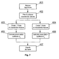
- Fig. 7 shows the procedure of operation of the frame type detector 203.
- the input frame is received in step 401 as a matrix describing its contents (pixel values).
- the frame is filtered in step 402 in order to enhance characteristic features of the frame, i.e. the features which can be recognized in a stereo frame and for which a shift between the left-eye frame and the right-eye frame can be measured.
- Such features are for example corners or edges of objects having a color different than a background color.
- Various image sharpening, edge detection, contrast enhancement etc. algorithms can be used.
- A is the input image matrix
- B is the filtered image matrix i,j are horizontal and vertical pixel coordinates
- the characteristic features of the filtered image are collected in two sets, each set describing a different half of the filtered image.
- the sets are created for the left and right half of the image in order to distinguish between a mono frame and a LR-type 3D frame
- the sets are created for the top and bottom half of the image in order to distinguish between a mono frame and a TB-type 3D frame.
- Each set comprises coordinates of the individual characteristic features.
- the characteristic features can be individual pixels of the filtered image having a value higher than a predefined threshold (i.e. the most contrasting pixels of the original image, such as the corners and edges of contrasting objects). Alternatively, a predetermined number of most characteristic features (i.e.
- each set may contain a predetermined number of randomly-selected characteristic features.
- the characteristic features can be also more complicated geometrical objects, such as lines, figures, areas of pixel concentration etc., detected using dedicated features detection algorithms.
- An exemplary list of features for the exemplary image shown in fig. 8 is shown in Fig. 9 .
- Fig. 8 shows an exemplary LR-type 3D frame, wherein the right part of the frame corresponds to the left part shifted slightly to the right.
- the filter algorithm described with reference to step 402 the most characteristic features of the images will be identified at the points of the corners of the geometrical figures, as they are mostly distinguishable from their neighboring pixels and less characteristic ones located on the remaining edges of the objects.
- the corresponding characteristic points on the image halves have been connected with dashed lines (not forming part of the source frame).
- Fig. 9 shows an exemplary features list for the left and right half of the frame of Fig. 8 . It is noted that the order in which the characteristic features are arranged on both lists is not relevant, as evident from the description of the algorithm of steps 405, 406.
- the top corner of the triangle of the left half of the frame is the fourth feature (D L ) on the left half features list and as the third feature (C R ) on the right half features list.
- Each element of the list (1-7) comprises the i,j coordinates of the characteristic feature.
- each characteristic feature of the first half of the frame is compared with each characteristic feature of the other half of the frame.
- the comparison is performed by calculating the difference in coordinates ( ⁇ i, ⁇ j) of the features.
- FIG. 10 presents exemplary plot of accumulation matrix (U ⁇ i, ⁇ j ) for an exemplary stereoscopic frame (with a larger number of characteristic features than that shown in Fig. 8 , such as points of frame borders and other possible characteristic points within the objects).
- the value of each element of the matrix (U ⁇ i, ⁇ j ) indicates the number of characteristic features that are shifted by the coordinate difference indicated by the particular element ( ⁇ i, ⁇ j).
- the peak value specifies the most frequent coordinate difference, i.e.
- the peak value is higher by a predefined threshold than a mean value for all values of the accumulation matrix - this indicates that the frame is a stereoscopic frame, and since the accumulation matrix was created by comparing the characteristic features for left half of the frame with the characteristic features for the right half of the frame, this indicated an LR-type frame.
- the predefined threshold may require the peak value to be e.g. at least 2 times higher than the mean value.
- the value by which the element of the matrix (U ⁇ i, ⁇ j ) is increased when a particular coordinate difference is detected can be a number different than 1, such as a number proportional to the strength of characteristics of a given characteristic points compared. Therefore, comparisons between the most characteristic points may result in a greater increase of the value of the element of the matrix (U ⁇ i, ⁇ j ) than comparisons between the least characteristic points.
- the neighboring elements of the accumulation matrix can be increased as well by a smaller amount, for example:
- the resolution of the accumulation matrix (U ⁇ i, ⁇ j ) can be adapted to the available memory and the processing power of the system.
- Fig. 11 presents an exemplary mono frame divided in half, wherein the characteristic features of the left half are not shifted by a common coordinate difference versus the characteristic features of the right half.
- Fig. 12 presents an exemplary plot of the accumulation matrix (U ⁇ i, ⁇ j ) for an exemplary mono frame (with a larger number of features than that shown in Fig. 11 " such as points of frame borders and other possible characteristic points within the objects), wherein there is no distinguishable peak, and therefore there is no correlation between characteristic features.
- the accumulation matrix V ⁇ i, ⁇ j is calculated in a way equivalent to step 405.
- the frame is classified as a 2D mono frame, or a 3D LR-type frame or TB-type frame.
- the classification may be a hard classification, wherein the frame is classified as a mono frame if no peaks were detected, as a LR-type frame if a peak has been detected in step 405 for the accumulation matrix U ⁇ i, ⁇ j and as a TB-type frame if a peak has been detected in step 406 for the accumulation matrix V ⁇ i, ⁇ j .
- the peak of the highest value can be selected to indicate the frame type.
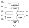
- Fig. 13 presents an exemplary embodiment of the frame type detector 203 according to the invention.
- the detector comprises a frame reader 501 configured to receive a video frame.
- a frame filter 502 is configured to filter the video frame to enhance characteristic features (A L -G L , A R -G R ) of the contents of the video frame, in a way equivalent to step 402.
- At least one list collector 503, 504 is configured to create a list of coordinates of at least part of the characteristic features for a first half of the frame (A L -G L ) and the other half (A R -G R ) of the frame, in a way equivalent to steps 403, 404.
- the list collector 403 may create lists for the left and right half of the frame and the list collector 404 may create lists for the top and bottom half of the frame.
- At least one accumulator 505, 506 configured to compare the coordinates (i,j) of the characteristic features of the list for the first half of the frame with the coordinates (i,j) of the characteristic features of the other half of the frame to obtain an accumulation matrix (U ⁇ i, ⁇ j , V ⁇ i, ⁇ j ) having a peak value (x LR , x TB ) specifying the most frequent coordinate difference and a mean value (m LR , m TB ) specifying the mean coordinate difference, in a way equivalent to steps 405, 406.
- a frame type classifier 507 is configured to classify the frame as a stereoscopic frame if the peak value (x LR , x TB ) exceeds the mean value (m LR , m TB ) by a predefined threshold and as a monoscopic frame otherwise, in a way equivalent to step 407.
- the frame type detector 203 can form a part of a multi-component system, in which a plurality of different frame type detectors are used, each configured to analyze the frame using a different algorithm configured to output a type coefficient indicative of a probability that the frame is of a 2D or 3D type, wherein the type coefficients from the frame type detectors are received by a controller configured to generate a predicted frame type indicator based on the received type coefficients.
- the determined frame type can be used to select the method of processing the signal to be displayed.
- the determined frame type can be used to select the method of processing the signal to be passed to a display unit, for example converting a 2D signal to a 3D format in case the display unit is set to receive 3D video signals.
- the aforementioned system and method for determining video frame type may be performed and/or controlled by one or more computer programs.
- Such computer programs are typically executed by utilizing the computing resources of a processing unit which can be embedded within various video signal receivers, such as personal computers, personal digital assistants, cellular telephones, receivers and decoders of digital television, video display units or the like.
- the computer programs can be stored in a non-volatile memory, for example a flash memory or in a volatile memory, for example RAM and are executed by the processing unit.
- These memories are exemplary recording media for storing computer programs comprising computer-executable instructions performing all the steps of the computer-implemented method according the technical concept presented herein.
Landscapes
- Engineering & Computer Science (AREA)
- Multimedia (AREA)
- Signal Processing (AREA)
- Testing, Inspecting, Measuring Of Stereoscopic Televisions And Televisions (AREA)
Abstract
Description
- The present invention relates to determining video frame type, in particular distinguishing between a two-dimensional (2D) and three-dimensional (3D) video frames.
- Stereoscopic video displays can be used to display both 2D and 3D video signals, by processing the frames of the signals depending on the type of signal. The type of the signal can be specified manually by the user, which can be troublesome for inexperienced users. The type of signal can be also specified by supplementary data included in the signal itself or by a supplementary signal, which requires the video display unit to be able to decode and recognize the supplementary data or the supplementary signal.
- A US patent application
US2009/0009508 presents an apparatus and a method for driving a 2D/3D switchable display, which includes an image mode determination unit determining whether input image signals of continuous frames are in a 2D mode or 3D mode. The 3D mode is recognized by determining a syntax indicating a stereo or a multiview image included in the header information of the input image signal. Alternatively, the image mode can be determined based on the presence of a stereo sync signal. Therefore, the mode determination requires data or signals supplementary to the basic image data. - A PCT patent application
W02010/014973 - In case the display lacks the functionality of decoding supplementary data included in the signal or is not able to decode supplementary signals describing the video type, or the video signal contains only basic image contents without the image type indicated, the signal must be recognized in an alternative way.
- The aim of the present invention is to provide a method for determining the video frame type by analyzing video signals having no or unknown indication of video frame type.
- The object of the invention is a computer-implemented method for determining a video frame type, comprising the steps of receiving a video frame, filtering the video frame to enhance characteristic features of the contents of the video frame, creating a list of coordinates of at least part of the characteristic features for a first half of the frame and the other half of the frame, comparing the coordinates of the characteristic features of the list for the first half of the frame with the coordinates of the characteristic features of the other half of the frame to obtain an accumulation matrix having a peak value specifying the most frequent coordinate difference and a mean value specifying the mean coordinate difference and classifying the frame as a stereoscopic frame if the peak value exceeds the mean value by a predefined threshold and as a monoscopic frame otherwise.
- The first half can be the left half, the other half can be the right half and the frame can be classified as a LR-type stereoscopic frame if the peak value exceeds the mean value by a threshold value.
- The first half can be the top half, the other half can be the bottom half and the frame can be classified as a TB-type stereoscopic frame if the peak value exceeds the mean value by a threshold value.
- A first set of lists of coordinates can be created for the left half and the right half of the frame, a second set of lists of coordinates can be created for the top half and the bottom half of the frame, a peak value and a mean value can be obtained for the first set and for the second set and the frame can be classified as a LR-type stereoscopic frame, a TB-type stereoscopic frame or a monoscopic frame.
- The method may further comprise the step of calculating a probability of a stereoscopic frame as a difference between 1 and a ratio of the mean value and the peak value.
- The characteristic features can be individual pixels of the video frame having a value different from the color of the neighboring pixels.
- A list of coordinates of a predetermined number of the most characteristic features can be created.
- A list of coordinates of the characteristic features having a parameter larger than a predetermined threshold value can be created.
- A list of coordinates of a predetermined number of randomly-selected characteristic features can be created.
- The accumulation matrix can be obtained by increasing the value of the element of the matrix corresponding to the detected difference between the compared coordinates of the characteristic features of the list for the first half of the frame with the coordinates of the characteristic features of the other half of the frame.
- The method may further comprise the step of increasing the value of the neighboring elements of the main element corresponding to the detected difference by a value smaller than the value of increase of the main element.
- The object of the invention is also a computer program comprising program code means for performing all the steps of the computer-implemented method of the invention when said program is run on a computer, as well as a computer readable medium storing computer-executable instructions performing all the steps of the computer-implemented method of the invention when executed on a computer.
- Another object of the invention is a system for determining a video frame type, comprising a frame reader configured to receive a video frame, a frame filter configured to filter the video frame to enhance characteristic features of the contents of the video frame, a list collector configured to create a list of coordinates of at least part of the characteristic features for a first half of the frame and the other half of the frame, an accumulator configured to compare the coordinates of the characteristic features of the list for the first half of the frame with the coordinates of the characteristic features of the other half of the frame to obtain an accumulation matrix having a peak value specifying the most frequent coordinate difference and a mean value specifying the mean coordinate difference and a frame type classifier configured to classify the frame as a stereoscopic frame if the peak value exceeds the mean value by a predefined threshold and as a monoscopic frame otherwise.
- The system may comprise a pair of list collectors configured to create a first set of lists of coordinates for the left half and the right half of the frame, creating a second set of lists of coordinates for the top half and the bottom half of the frame, and a pair of accumulators configured to obtain a peak value and a mean value for the first set and for the second set, wherein the frame type classifier is configured to classify the frame as a LT-type stereoscopic frame, a TB-type stereoscopic frame or a monoscopic frame.
- The present invention will be shown by means of an exemplary embodiment on a drawing, in which:
-
Figs. 1A-1D show examples of typical 2D video frames. -
Figs. 2A-2H show examples of typical 3D video frames of an Left-Right (LR) type. -
Figs. 3A-3H show examples of typical 3D video frames of a Top-Bottom (TB) type. -
Fig. 4 shows the common non-active image regions of a video frame. -
Fig. 5 shows the structure of a system for determining video frame type. -
Fig. 6 shows the procedure of operation of a frame compactor. -
Fig. 7 shows the procedure of operation of a frame type detector. -
Fig. 8 shows an exemplary LR-type 3D frame -
Fig. 9 shows an exemplary features list for the left and right half of the frame ofFig. 8 . -
Fig. 10 presents exemplary plot of values of the accumulation matrix for an exemplary stereoscopic frame. -
Fig. 11 presents an exemplary mono frame. -
Fig. 12 presents an exemplary plot of the accumulation matrix for an exemplary mono frame. -
Fig. 13 presents an exemplary embodiment of the frame type detector. -
Figs. 1A-1D show examples of typical 2D video frames. The frame may comprise only anactive image region 111 as shown inFig. 1A . Alternatively, the 2D frame may further comprise anon-active image region 110, such as bars of a uniform color, e.g. black, at the top and bottom edges of the frame as shown inFig. 1B or bars at the top, bottom, left and right edges of the frame as shown inFig. 1C or bars at the left and right edges of the frame as shown inFig. 1D . -
Figs. 2A-2H show examples of typical 3D video frames of a Left-Right (LR) type. Such frame, as shown inFig. 2A , comprises twoactive image regions active regions non-active image regions 110, such as bars of a uniform color, e.g. black, at the top and bottom edges of the frame as shown inFig. 2B , at the top, bottom, left and right edges of the frame as shown inFig. 2C , at the left and right edges of the frame as shown inFig. 2D , at the top, bottom, left and right edges of the frame and between the active regions as shown inFig. 2E , at the left and right edges of the frame and between the active regions as shown inFig. 2F , between the active regions as shown inFig. 2G or at the top and bottom edges of the frame and between the active regions as shown inFig. 2H . -
Figs. 3A-3H show examples of typical 3D video frames of a Top-Bottom (TB) type. Such frame, as shown inFig. 3A , comprises twoactive image regions active regions non-active image regions 110, such as: bars of a uniform color, e.g. black, at the left and right edges of the frame as shown inFig. 3B , at the top, bottom, left and right edges of the frame as shown inFig. 3C , at the top and bottom edges of the frame as shown inFig. 3D , at the top, bottom, left and right edges of the frame and between the active regions as shown inFig. 3E , at the top and bottom edges of the frame and between the active regions as shown inFig. 3F , between the active regions as shown inFig. 3G or at the left and right edges of the frame and between the active regions as shown inFig. 3H . - Therefore, for any 2D or 3D video frame, the most probable
non-active regions 110 may form bars at the top, bottom, left, right, horizontal centre and vertical centre of the frame, as shown inFig. 4 . -
Fig. 5 shows the structure of a system for determining video frame type according to the invention. The system comprises aframe compactor 201 configured to extract from the input video frames data representing an active region and discard the data representing the non-active region of the frame, according to the procedure shown inFig. 6 , and possibly to reduce the amount of data by scaling-down and/or discarding the color information. The reduced frame representation is passed to abuffer 202, from which it is collected by aframe type detector 203 operating according to the procedure shown inFig. 7 Theframe type detector 203 provides an output specifying the type of the frame: that the frame is a 2D or a 3D frame, wherein for 3D frames the detector may indicate the type of frame as an LR frame (p LR) or a TB frame (p TB). In a simple embodiment, the system may be adapted to distinguish only between mono frames and one type of 3D frames, i.e. LR-type or TB-type frames. -
Fig. 6 shows the procedure of operation of theframe compactor 201. Instep 301 the color information can be discarded, either by converting the frame contents into a grayscale or selecting contents of only one color channel. Next, instep 302, the received input frame may be reduced for easier analysis, by scaling it down, i.e. reducing the size of the frame. Next, instep 303 the frame is analyzed to detect the non-active regions, preferably in areas indicated inFig. 4 , namely in the bars located at the top, bottom, left, right, horizontal centre and vertical centre of the frame. The contents of the detected non-active regions are discarded instep 304 so as to generate a frame containing only data of active regions, as shown inFig. 1A ,2A or3A . The processing of a frame by theframe compactor 201 may be initiated after a change of the video input signal, for example a change of a channel in a television decoder, in order to determine the type of the new signal. Alternatively, theframe compactor 201 may be operated continuously, in order to detect change of type of the received signal, for example to detect a 2D commercial break in a 3D video film. In such a case, theframe compactor 201 may receive the frames with a specific frequency, preferably lower than the frame display rate, such as 2 frames per second, in order to minimize the computational load of the signal receiver. -
Fig. 7 shows the procedure of operation of theframe type detector 203. The input frame is received instep 401 as a matrix describing its contents (pixel values). Next, the frame is filtered instep 402 in order to enhance characteristic features of the frame, i.e. the features which can be recognized in a stereo frame and for which a shift between the left-eye frame and the right-eye frame can be measured. Such features are for example corners or edges of objects having a color different than a background color. Various image sharpening, edge detection, contrast enhancement etc. algorithms can be used. For example, all pixels of the image can be filtered with the following algorithm, which enhances the value of pixels which differ from their neighboring left, right, top and bottom pixels and zeroes the pixels which have the same value as their neighboring pixels:

wherein
A is the input image matrix
B is the filtered image matrix
i,j are horizontal and vertical pixel coordinates - Next, in
steps step 403 the sets are created for the left and right half of the image in order to distinguish between a mono frame and a LR-type 3D frame, and instep 404 the sets are created for the top and bottom half of the image in order to distinguish between a mono frame and a TB-type 3D frame. Each set comprises coordinates of the individual characteristic features. The characteristic features can be individual pixels of the filtered image having a value higher than a predefined threshold (i.e. the most contrasting pixels of the original image, such as the corners and edges of contrasting objects). Alternatively, a predetermined number of most characteristic features (i.e. having the highest values) can be selected. Furthermore, each set may contain a predetermined number of randomly-selected characteristic features. The characteristic features can be also more complicated geometrical objects, such as lines, figures, areas of pixel concentration etc., detected using dedicated features detection algorithms. An exemplary list of features for the exemplary image shown infig. 8 is shown inFig. 9 . - The procedure for creating the LR-type list can be summarized by equations:
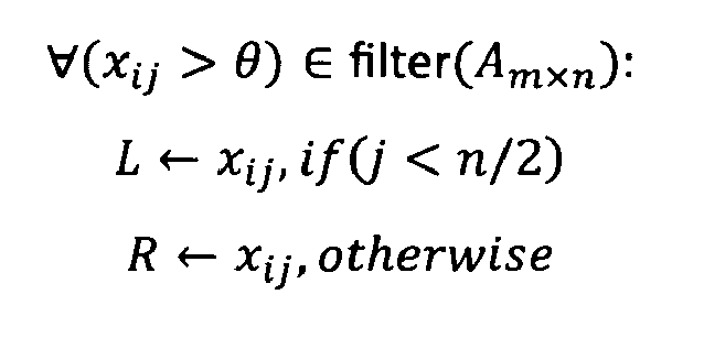
wherein
(m x n) is the image size specified as a number of pixels in horizontal and vertical direction
L, R is the characteristic features set for the left and right half of the frame, respectively - The procedure for creating the TB-type list can be summarized by equations:
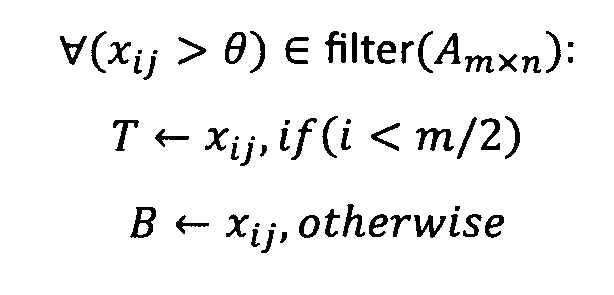
wherein
T, B is the characteristic features set for the top and bottom half of the frame, respectively -
Fig. 8 shows an exemplary LR-type 3D frame, wherein the right part of the frame corresponds to the left part shifted slightly to the right. Using the filter algorithm described with reference to step 402, the most characteristic features of the images will be identified at the points of the corners of the geometrical figures, as they are mostly distinguishable from their neighboring pixels and less characteristic ones located on the remaining edges of the objects. The corresponding characteristic points on the image halves have been connected with dashed lines (not forming part of the source frame). -
Fig. 9 shows an exemplary features list for the left and right half of the frame ofFig. 8 . It is noted that the order in which the characteristic features are arranged on both lists is not relevant, as evident from the description of the algorithm ofsteps - In
step 405 the set for the left frame half is compared with the set for the right frame half according to the algorithm:


wherein
UΔi,Δj is an accumulation matrix specifying the number of characteristic features of the left (L) half of the image which are shifted by (Δi,Δj) with respect to the characteristic features of the right (R) half of the image. - Therefore, each characteristic feature of the first half of the frame is compared with each characteristic feature of the other half of the frame. The comparison is performed by calculating the difference in coordinates (Δi,Δj) of the features. When corresponding features of a 3D LR-type signal are compared with each other (i.e. AL with BR, BL with AL, CL with ER, DL with CR, EL with DR, FL with GR and GL with FR), the comparison will result in the same difference in coordinates, where the horizontal axis coordinate difference (Δi) will be equal to the amount of the horizontal shift between the two pictures and the vertical axis coordinate difference (Δj) will be usually equal to zero, as the LR-type image is usually not shifted in the vertical direction. A comparison between non-corresponding features (e.g. AL with AR, CR, DR, ER, FR, GR, BL with BR, CR, DR, ER, FR, GR, etc) will result in various values.
Fig. 10 presents exemplary plot of accumulation matrix (UΔi,Δj) for an exemplary stereoscopic frame (with a larger number of characteristic features than that shown inFig. 8 , such as points of frame borders and other possible characteristic points within the objects). The value of each element of the matrix (UΔi,Δj) indicates the number of characteristic features that are shifted by the coordinate difference indicated by the particular element (Δi,Δj). The peak value specifies the most frequent coordinate difference, i.e. corresponds substantially to the amount of shift between the left and right half of the frame. If the peak value is higher by a predefined threshold than a mean value for all values of the accumulation matrix - this indicates that the frame is a stereoscopic frame, and since the accumulation matrix was created by comparing the characteristic features for left half of the frame with the characteristic features for the right half of the frame, this indicated an LR-type frame. The predefined threshold may require the peak value to be e.g. at least 2 times higher than the mean value. - Alternatively, the value by which the element of the matrix (UΔi,Δj) is increased when a particular coordinate difference is detected can be a number different than 1, such as a number proportional to the strength of characteristics of a given characteristic points compared. Therefore, comparisons between the most characteristic points may result in a greater increase of the value of the element of the matrix (UΔi,Δj) than comparisons between the least characteristic points.
- Moreover, simultaneously with increasing the element of the accumulation matrix (UΔi,Δi) corresponding to a particular coordinate difference, the neighboring elements of the accumulation matrix can be increased as well by a smaller amount, for example:
- the element of coordinates (Δi,Δj) can be increased by 1.
- the elements of coordinates (Δi-1, Δj) (Δi+1, Δj), (Δi, Δj-1), (Δi, Δj+1) can be increased by a smaller amount, such as 0,5
- the elements of coordinates (Δi-1, Δj-1), (Δi-1, Δj+1), (Δi+1, Δj-1), (Δi+1, Δj+1) can be increased by a smaller amount, such as 0,1.
- Increasing the values of the neighboring elements (Δi-1, Δj) (Δi+1, Δj), (Δi, Δj-1), (Δi, Δj+1), (Δi-1, Δj-1), (Δi-1, Δj+1), (Δi+1, Δj-1), (Δi+1, Δj+1) by smaller amount than the main element (Δi,Δj) allows to decrease the level of noise within the accumulation matrix.
- The resolution of the accumulation matrix (UΔi,Δj) can be adapted to the available memory and the processing power of the system.
- In turn,
Fig. 11 presents an exemplary mono frame divided in half, wherein the characteristic features of the left half are not shifted by a common coordinate difference versus the characteristic features of the right half.Fig. 12 presents an exemplary plot of the accumulation matrix (UΔi,Δj) for an exemplary mono frame (with a larger number of features than that shown inFig. 11 " such as points of frame borders and other possible characteristic points within the objects), wherein there is no distinguishable peak, and therefore there is no correlation between characteristic features. - In
step 406 the set of characteristic features for the top frame half is compared with the set for the bottom frame half according to the algorithm:


- The accumulation matrix VΔi,Δj is calculated in a way equivalent to step 405.
- Finally, in
step 407 the frame is classified as a 2D mono frame, or a 3D LR-type frame or TB-type frame. The classification may be a hard classification, wherein the frame is classified as a mono frame if no peaks were detected, as a LR-type frame if a peak has been detected instep 405 for the accumulation matrix UΔi,Δj and as a TB-type frame if a peak has been detected instep 406 for the accumulation matrix VΔi,Δj. In case the peaks were detected both insteps - The classification can be also a soft classification, providing a probability coefficient indicating each frame type, calculated as:


wherein
mLR is the mean value for the UΔi,Δj accumulation matrix
xLR is the peak value for the UΔi,Δj accumulation matrix
mTB is the mean value for the VΔi,Δj accumulation matrix
xTB is the peak value for the VΔi,Δj accumulation matrix -
Fig. 13 presents an exemplary embodiment of theframe type detector 203 according to the invention. The detector comprises aframe reader 501 configured to receive a video frame. Aframe filter 502 is configured to filter the video frame to enhance characteristic features (AL-GL, AR-GR) of the contents of the video frame, in a way equivalent to step 402. At least onelist collector steps list collector 403 may create lists for the left and right half of the frame and thelist collector 404 may create lists for the top and bottom half of the frame. At least oneaccumulator steps frame type classifier 507 is configured to classify the frame as a stereoscopic frame if the peak value (xLR, xTB) exceeds the mean value (mLR, mTB) by a predefined threshold and as a monoscopic frame otherwise, in a way equivalent to step 407. - The
frame type detector 203 can form a part of a multi-component system, in which a plurality of different frame type detectors are used, each configured to analyze the frame using a different algorithm configured to output a type coefficient indicative of a probability that the frame is of a 2D or 3D type, wherein the type coefficients from the frame type detectors are received by a controller configured to generate a predicted frame type indicator based on the received type coefficients. - In case the system according to the invention is embedded in a video display unit, the determined frame type can be used to select the method of processing the signal to be displayed. In case the system according to the invention is embedded in a video decoder, such as a television set-top box, the determined frame type can be used to select the method of processing the signal to be passed to a display unit, for example converting a 2D signal to a 3D format in case the display unit is set to receive 3D video signals.
- It can be easily recognized, by one skilled in the art, that the aforementioned system and method for determining video frame type may be performed and/or controlled by one or more computer programs. Such computer programs are typically executed by utilizing the computing resources of a processing unit which can be embedded within various video signal receivers, such as personal computers, personal digital assistants, cellular telephones, receivers and decoders of digital television, video display units or the like. The computer programs can be stored in a non-volatile memory, for example a flash memory or in a volatile memory, for example RAM and are executed by the processing unit. These memories are exemplary recording media for storing computer programs comprising computer-executable instructions performing all the steps of the computer-implemented method according the technical concept presented herein.
- While the invention presented herein has been depicted, described, and has been defined with reference to particular preferred embodiments, such references and examples of implementation in the foregoing specification do not imply any limitation on the invention. It will, however, be evident that various modifications and changes may be made thereto without departing from the broader scope of the technical concept. The presented preferred embodiments are exemplary only, and are not exhaustive of the scope of the technical concept presented herein. Accordingly, the scope of protection is not limited to the preferred embodiments described in the specification, but is only limited by the claims that follow.
Claims (15)
- A computer-implemented method for determining a video frame type, characterized in that it comprises the steps of:- receiving a video frame,- filtering the video frame to enhance characteristic features (AL-GL, AR-GR) of the contents of the video frame,- creating a list of coordinates of at least part of the characteristic features for a first half of the frame (AL-GL) and the other half (AR-GR) of the frame,- comparing the coordinates (i,j) of the characteristic features of the list for the first half of the frame with the coordinates (i,j) of the characteristic features of the other half of the frame to obtain an accumulation matrix (UΔi,Δj, VΔi,Δj) having a peak value (xLR, xTB) specifying the most frequent coordinate difference and a mean value (mLR, mTB) specifying the mean coordinate difference,- classifying the frame as a stereoscopic frame if the peak value (xLR, xTB) exceeds the mean value (mLR, mTB) by a predefined threshold and as a monoscopic frame otherwise.
- The method according to claim 1, wherein the first half is the left half, the other half is the right half and the frame is classified as a LR-type stereoscopic frame if the peak value (xLR) exceeds the mean value (mLR) by a threshold value.
- The method according to claim 1, wherein the first half is the top half, the other half is the bottom half and the frame is classified as a TB-type stereoscopic frame if the peak value (xTB) exceeds the mean value (mTB) by a threshold value.
- The method according to claims 2 and 3, characterized by creating a first set of lists of coordinates for the left half and the right half of the frame, creating a second set of lists of coordinates for the top half and the bottom half of the frame, obtaining a peak value (xLR, xTB) and a mean value (mLR, mTB) for the first set and for the second set and classifying the frame as a LR-type stereoscopic frame, a TB-type stereoscopic frame or a monoscopic frame.
- The method according to any of previous claims, further comprising the step of calculating a probability of a stereoscopic frame as a difference between 1 and a ratio of the mean value (mLR, mTB) and the peak value (xLR, xTB).
- The method according to any of previous claims, wherein the characteristic features are individual pixels of the video frame having a value different from the color of the neighboring pixels.
- The method according to any of previous claims, characterized by creating a list of coordinates of a predetermined number of the most characteristic features.
- The method according to any of previous claims, characterized by creating a list of coordinates of the characteristic features having a parameter larger than a predetermined threshold value.
- The method according to any of previous claims, characterized by creating a list of coordinates of a predetermined number of randomly-selected characteristic features.
- The method according to any of previous claims, characterized by obtaining the accumulation matrix (UΔi,Δj, VΔi,Δj) by increasing the value of the element (Δi,Δj) of the matrix (UΔi,Δj, VΔi,Δj) corresponding to the detected difference (Δi,Δj) between the compared coordinates (i,j) of the characteristic features of the list for the first half of the frame with the coordinates (i,j) of the characteristic features of the other half of the frame.
- The method according to claim 10, further comprising the step of increasing the value of the neighboring elements (Δi-1, Δj) (Δi+1, Δj), (Δi, Δj-1), (Δi, Δj+1), (Δi-1, Δj-1), (Δi-1, Δj+1), (Δi+1, Δj-1), (Δi+1, Δj+1) of the main element (Δi,Δj) corresponding to the detected difference (Δi,Δj) by a value smaller than the value of increase of the main element (Δi,Δj).
- A computer program comprising program code means for performing all the steps of the computer-implemented method according to any of claims 1-11 when said program is run on a computer.
- A computer readable medium storing computer-executable instructions performing all the steps of the computer-implemented method according to any of claims 1-11 when executed on a computer.
- A system for determining a video frame type, characterized in that it comprises:- a frame reader (501) configured to receive a video frame,- a frame filter (502) configured to filter the video frame to enhance characteristic features (AL-GL, AR-GR) of the contents of the video frame,- a list collector (503, 504) configured to create a list of coordinates of at least part of the characteristic features for a first half of the frame (AL-GL) and the other half (AR-GR) of the frame,- an accumulator (505, 506) configured to compare the coordinates (i,j) of the characteristic features of the list for the first half of the frame with the coordinates (i,j) of the characteristic features of the other half of the frame to obtain an accumulation matrix (UΔi,Δj, VΔi,Δj) having a peak value (xLR, xTB) specifying the most frequent coordinate difference and a mean value (mLR, mTB) specifying the mean coordinate difference,- a frame type classifier (507) configured to classify the frame as a stereoscopic frame if the peak value (xLR, xTB) exceeds the mean value (mLR, mTB) by a predefined threshold and as a monoscopic frame otherwise.
- The system according to claim 14, comprising a pair of list collectors (503, 504) configured to create a first set of lists of coordinates for the left half and the right half of the frame, creating a second set of lists of coordinates for the top half and the bottom half of the frame, and a pair of accumulators (505, 506) configured to obtain a peak value (xLR, xTB) and a mean value (mLR, mTB) for the first set and for the second set, wherein the frame type classifier (507) is configured to classify the frame as a LT-type stereoscopic frame, a TB-type stereoscopic frame or a monoscopic frame.
Priority Applications (1)
| Application Number | Priority Date | Filing Date | Title |
|---|---|---|---|
| EP11000290.4A EP2477407B1 (en) | 2011-01-15 | 2011-01-15 | A method and a system for determining a video frame type |
Applications Claiming Priority (1)
| Application Number | Priority Date | Filing Date | Title |
|---|---|---|---|
| EP11000290.4A EP2477407B1 (en) | 2011-01-15 | 2011-01-15 | A method and a system for determining a video frame type |
Publications (2)
| Publication Number | Publication Date |
|---|---|
| EP2477407A1 true EP2477407A1 (en) | 2012-07-18 |
| EP2477407B1 EP2477407B1 (en) | 2018-03-21 |
Family
ID=43902814
Family Applications (1)
| Application Number | Title | Priority Date | Filing Date |
|---|---|---|---|
| EP11000290.4A Active EP2477407B1 (en) | 2011-01-15 | 2011-01-15 | A method and a system for determining a video frame type |
Country Status (1)
| Country | Link |
|---|---|
| EP (1) | EP2477407B1 (en) |
Cited By (1)
| Publication number | Priority date | Publication date | Assignee | Title |
|---|---|---|---|---|
| CN103593837A (en) * | 2012-08-15 | 2014-02-19 | 联咏科技股份有限公司 | Method for automatically detecting image format and related device |
Citations (3)
| Publication number | Priority date | Publication date | Assignee | Title |
|---|---|---|---|---|
| US20090009508A1 (en) | 2007-07-06 | 2009-01-08 | Samsung Electronics Co., Ltd. | Apparatus and method for driving 2d/3d switchable display |
| WO2010014973A1 (en) | 2008-08-01 | 2010-02-04 | Real D | Method and apparatus to mark and identify stereoscopic video frames |
| US20100182404A1 (en) * | 2008-12-05 | 2010-07-22 | Panasonic Corporation | Three dimensional video reproduction apparatus, three dimensional video reproduction system, three dimensional video reproduction method, and semiconductor device for three dimensional video reproduction |
-
2011
- 2011-01-15 EP EP11000290.4A patent/EP2477407B1/en active Active
Patent Citations (3)
| Publication number | Priority date | Publication date | Assignee | Title |
|---|---|---|---|---|
| US20090009508A1 (en) | 2007-07-06 | 2009-01-08 | Samsung Electronics Co., Ltd. | Apparatus and method for driving 2d/3d switchable display |
| WO2010014973A1 (en) | 2008-08-01 | 2010-02-04 | Real D | Method and apparatus to mark and identify stereoscopic video frames |
| US20100182404A1 (en) * | 2008-12-05 | 2010-07-22 | Panasonic Corporation | Three dimensional video reproduction apparatus, three dimensional video reproduction system, three dimensional video reproduction method, and semiconductor device for three dimensional video reproduction |
Cited By (1)
| Publication number | Priority date | Publication date | Assignee | Title |
|---|---|---|---|---|
| CN103593837A (en) * | 2012-08-15 | 2014-02-19 | 联咏科技股份有限公司 | Method for automatically detecting image format and related device |
Also Published As
| Publication number | Publication date |
|---|---|
| EP2477407B1 (en) | 2018-03-21 |
Similar Documents
| Publication | Publication Date | Title |
|---|---|---|
| US9905031B2 (en) | Method and related apparatus for capturing and processing image data | |
| EP2382791B1 (en) | Depth and video co-processing | |
| RU2469418C2 (en) | Image processing device, image processing method and program | |
| CN102461185B (en) | Method and device for automatic conversion of 3D video | |
| US8817020B2 (en) | Image processing apparatus and image processing method thereof | |
| TWI469623B (en) | Method for distinguishing a 3d image from a 2d image and for identifying the presence of a 3d image format by feature correspondence determination | |
| US8805020B2 (en) | Apparatus and method for generating depth signal | |
| US9237326B2 (en) | Imaging system and method | |
| US9185400B2 (en) | Method and a system for determining a video frame type | |
| US20140333720A1 (en) | Subtitle detection for stereoscopic video contents | |
| KR101797035B1 (en) | Method for converting overlaying area into 3D image and apparatus thereof | |
| CN103049908B (en) | The method and apparatus generating stereoscopic video file | |
| EP2477407B1 (en) | A method and a system for determining a video frame type | |
| US10096116B2 (en) | Method and apparatus for segmentation of 3D image data | |
| EP2426931A1 (en) | A method and a system for determining a video frame type | |
| EP2658265B1 (en) | Adaptive depth offset calculation for an image | |
| CN104185023A (en) | Automatic detecting method and device for three-dimensional video format | |
| EP2963924B1 (en) | A method and a system for determining a video frame type | |
| EP2477406B1 (en) | A method and a system for determining a video frame type | |
| KR20140029454A (en) | Method and system for decoding a stereoscopic video signal | |
| WO2017113735A1 (en) | Video format distinguishing method and system | |
| EP2932466B1 (en) | Method and apparatus for segmentation of 3d image data | |
| CN103763545B (en) | A kind of free stereo image processing method and device, electronic equipment | |
| WO2014025295A1 (en) | 2d/3d image format detection | |
| KR102276628B1 (en) | Image process device and display apparatus having the same |
Legal Events
| Date | Code | Title | Description |
|---|---|---|---|
| PUAI | Public reference made under article 153(3) epc to a published international application that has entered the european phase |
Free format text: ORIGINAL CODE: 0009012 |
|
| AK | Designated contracting states |
Kind code of ref document: A1 Designated state(s): AL AT BE BG CH CY CZ DE DK EE ES FI FR GB GR HR HU IE IS IT LI LT LU LV MC MK MT NL NO PL PT RO RS SE SI SK SM TR |
|
| AX | Request for extension of the european patent |
Extension state: BA ME |
|
| 17P | Request for examination filed |
Effective date: 20130102 |
|
| 17Q | First examination report despatched |
Effective date: 20140106 |
|
| STAA | Information on the status of an ep patent application or granted ep patent |
Free format text: STATUS: EXAMINATION IS IN PROGRESS |
|
| GRAP | Despatch of communication of intention to grant a patent |
Free format text: ORIGINAL CODE: EPIDOSNIGR1 |
|
| STAA | Information on the status of an ep patent application or granted ep patent |
Free format text: STATUS: GRANT OF PATENT IS INTENDED |
|
| GRAS | Grant fee paid |
Free format text: ORIGINAL CODE: EPIDOSNIGR3 |
|
| GRAA | (expected) grant |
Free format text: ORIGINAL CODE: 0009210 |
|
| STAA | Information on the status of an ep patent application or granted ep patent |
Free format text: STATUS: THE PATENT HAS BEEN GRANTED |
|
| INTG | Intention to grant announced |
Effective date: 20180122 |
|
| AK | Designated contracting states |
Kind code of ref document: B1 Designated state(s): AL AT BE BG CH CY CZ DE DK EE ES FI FR GB GR HR HU IE IS IT LI LT LU LV MC MK MT NL NO PL PT RO RS SE SI SK SM TR |
|
| REG | Reference to a national code |
Ref country code: GB Ref legal event code: FG4D |
|
| REG | Reference to a national code |
Ref country code: CH Ref legal event code: EP |
|
| REG | Reference to a national code |
Ref country code: AT Ref legal event code: REF Ref document number: 982339 Country of ref document: AT Kind code of ref document: T Effective date: 20180415 |
|
| REG | Reference to a national code |
Ref country code: IE Ref legal event code: FG4D |
|
| REG | Reference to a national code |
Ref country code: DE Ref legal event code: R096 Ref document number: 602011046608 Country of ref document: DE |
|
| REG | Reference to a national code |
Ref country code: NL Ref legal event code: MP Effective date: 20180321 |
|
| PG25 | Lapsed in a contracting state [announced via postgrant information from national office to epo] |
Ref country code: LT Free format text: LAPSE BECAUSE OF FAILURE TO SUBMIT A TRANSLATION OF THE DESCRIPTION OR TO PAY THE FEE WITHIN THE PRESCRIBED TIME-LIMIT Effective date: 20180321 Ref country code: CY Free format text: LAPSE BECAUSE OF FAILURE TO SUBMIT A TRANSLATION OF THE DESCRIPTION OR TO PAY THE FEE WITHIN THE PRESCRIBED TIME-LIMIT Effective date: 20180321 Ref country code: HR Free format text: LAPSE BECAUSE OF FAILURE TO SUBMIT A TRANSLATION OF THE DESCRIPTION OR TO PAY THE FEE WITHIN THE PRESCRIBED TIME-LIMIT Effective date: 20180321 Ref country code: NO Free format text: LAPSE BECAUSE OF FAILURE TO SUBMIT A TRANSLATION OF THE DESCRIPTION OR TO PAY THE FEE WITHIN THE PRESCRIBED TIME-LIMIT Effective date: 20180621 Ref country code: FI Free format text: LAPSE BECAUSE OF FAILURE TO SUBMIT A TRANSLATION OF THE DESCRIPTION OR TO PAY THE FEE WITHIN THE PRESCRIBED TIME-LIMIT Effective date: 20180321 |
|
| REG | Reference to a national code |
Ref country code: LT Ref legal event code: MG4D |
|
| REG | Reference to a national code |
Ref country code: AT Ref legal event code: MK05 Ref document number: 982339 Country of ref document: AT Kind code of ref document: T Effective date: 20180321 |
|
| PG25 | Lapsed in a contracting state [announced via postgrant information from national office to epo] |
Ref country code: BG Free format text: LAPSE BECAUSE OF FAILURE TO SUBMIT A TRANSLATION OF THE DESCRIPTION OR TO PAY THE FEE WITHIN THE PRESCRIBED TIME-LIMIT Effective date: 20180621 Ref country code: GR Free format text: LAPSE BECAUSE OF FAILURE TO SUBMIT A TRANSLATION OF THE DESCRIPTION OR TO PAY THE FEE WITHIN THE PRESCRIBED TIME-LIMIT Effective date: 20180622 Ref country code: SE Free format text: LAPSE BECAUSE OF FAILURE TO SUBMIT A TRANSLATION OF THE DESCRIPTION OR TO PAY THE FEE WITHIN THE PRESCRIBED TIME-LIMIT Effective date: 20180321 Ref country code: LV Free format text: LAPSE BECAUSE OF FAILURE TO SUBMIT A TRANSLATION OF THE DESCRIPTION OR TO PAY THE FEE WITHIN THE PRESCRIBED TIME-LIMIT Effective date: 20180321 Ref country code: RS Free format text: LAPSE BECAUSE OF FAILURE TO SUBMIT A TRANSLATION OF THE DESCRIPTION OR TO PAY THE FEE WITHIN THE PRESCRIBED TIME-LIMIT Effective date: 20180321 |
|
| PG25 | Lapsed in a contracting state [announced via postgrant information from national office to epo] |
Ref country code: NL Free format text: LAPSE BECAUSE OF FAILURE TO SUBMIT A TRANSLATION OF THE DESCRIPTION OR TO PAY THE FEE WITHIN THE PRESCRIBED TIME-LIMIT Effective date: 20180321 Ref country code: PL Free format text: LAPSE BECAUSE OF FAILURE TO SUBMIT A TRANSLATION OF THE DESCRIPTION OR TO PAY THE FEE WITHIN THE PRESCRIBED TIME-LIMIT Effective date: 20180321 Ref country code: AL Free format text: LAPSE BECAUSE OF FAILURE TO SUBMIT A TRANSLATION OF THE DESCRIPTION OR TO PAY THE FEE WITHIN THE PRESCRIBED TIME-LIMIT Effective date: 20180321 Ref country code: ES Free format text: LAPSE BECAUSE OF FAILURE TO SUBMIT A TRANSLATION OF THE DESCRIPTION OR TO PAY THE FEE WITHIN THE PRESCRIBED TIME-LIMIT Effective date: 20180321 Ref country code: RO Free format text: LAPSE BECAUSE OF FAILURE TO SUBMIT A TRANSLATION OF THE DESCRIPTION OR TO PAY THE FEE WITHIN THE PRESCRIBED TIME-LIMIT Effective date: 20180321 Ref country code: EE Free format text: LAPSE BECAUSE OF FAILURE TO SUBMIT A TRANSLATION OF THE DESCRIPTION OR TO PAY THE FEE WITHIN THE PRESCRIBED TIME-LIMIT Effective date: 20180321 |
|
| PG25 | Lapsed in a contracting state [announced via postgrant information from national office to epo] |
Ref country code: CZ Free format text: LAPSE BECAUSE OF FAILURE TO SUBMIT A TRANSLATION OF THE DESCRIPTION OR TO PAY THE FEE WITHIN THE PRESCRIBED TIME-LIMIT Effective date: 20180321 Ref country code: AT Free format text: LAPSE BECAUSE OF FAILURE TO SUBMIT A TRANSLATION OF THE DESCRIPTION OR TO PAY THE FEE WITHIN THE PRESCRIBED TIME-LIMIT Effective date: 20180321 Ref country code: SM Free format text: LAPSE BECAUSE OF FAILURE TO SUBMIT A TRANSLATION OF THE DESCRIPTION OR TO PAY THE FEE WITHIN THE PRESCRIBED TIME-LIMIT Effective date: 20180321 Ref country code: SK Free format text: LAPSE BECAUSE OF FAILURE TO SUBMIT A TRANSLATION OF THE DESCRIPTION OR TO PAY THE FEE WITHIN THE PRESCRIBED TIME-LIMIT Effective date: 20180321 |
|
| PG25 | Lapsed in a contracting state [announced via postgrant information from national office to epo] |
Ref country code: PT Free format text: LAPSE BECAUSE OF FAILURE TO SUBMIT A TRANSLATION OF THE DESCRIPTION OR TO PAY THE FEE WITHIN THE PRESCRIBED TIME-LIMIT Effective date: 20180723 |
|
| REG | Reference to a national code |
Ref country code: DE Ref legal event code: R097 Ref document number: 602011046608 Country of ref document: DE |
|
| PLBE | No opposition filed within time limit |
Free format text: ORIGINAL CODE: 0009261 |
|
| STAA | Information on the status of an ep patent application or granted ep patent |
Free format text: STATUS: NO OPPOSITION FILED WITHIN TIME LIMIT |
|
| PG25 | Lapsed in a contracting state [announced via postgrant information from national office to epo] |
Ref country code: DK Free format text: LAPSE BECAUSE OF FAILURE TO SUBMIT A TRANSLATION OF THE DESCRIPTION OR TO PAY THE FEE WITHIN THE PRESCRIBED TIME-LIMIT Effective date: 20180321 |
|
| 26N | No opposition filed |
Effective date: 20190102 |
|
| PG25 | Lapsed in a contracting state [announced via postgrant information from national office to epo] |
Ref country code: IT Free format text: LAPSE BECAUSE OF FAILURE TO SUBMIT A TRANSLATION OF THE DESCRIPTION OR TO PAY THE FEE WITHIN THE PRESCRIBED TIME-LIMIT Effective date: 20180321 |
|
| PG25 | Lapsed in a contracting state [announced via postgrant information from national office to epo] |
Ref country code: SI Free format text: LAPSE BECAUSE OF FAILURE TO SUBMIT A TRANSLATION OF THE DESCRIPTION OR TO PAY THE FEE WITHIN THE PRESCRIBED TIME-LIMIT Effective date: 20180321 |
|
| PG25 | Lapsed in a contracting state [announced via postgrant information from national office to epo] |
Ref country code: MC Free format text: LAPSE BECAUSE OF FAILURE TO SUBMIT A TRANSLATION OF THE DESCRIPTION OR TO PAY THE FEE WITHIN THE PRESCRIBED TIME-LIMIT Effective date: 20180321 |
|
| REG | Reference to a national code |
Ref country code: CH Ref legal event code: PL |
|
| PG25 | Lapsed in a contracting state [announced via postgrant information from national office to epo] |
Ref country code: LU Free format text: LAPSE BECAUSE OF NON-PAYMENT OF DUE FEES Effective date: 20190115 |
|
| REG | Reference to a national code |
Ref country code: BE Ref legal event code: MM Effective date: 20190131 |
|
| REG | Reference to a national code |
Ref country code: IE Ref legal event code: MM4A |
|
| PG25 | Lapsed in a contracting state [announced via postgrant information from national office to epo] |
Ref country code: BE Free format text: LAPSE BECAUSE OF NON-PAYMENT OF DUE FEES Effective date: 20190131 |
|
| PG25 | Lapsed in a contracting state [announced via postgrant information from national office to epo] |
Ref country code: CH Free format text: LAPSE BECAUSE OF NON-PAYMENT OF DUE FEES Effective date: 20190131 Ref country code: LI Free format text: LAPSE BECAUSE OF NON-PAYMENT OF DUE FEES Effective date: 20190131 |
|
| PG25 | Lapsed in a contracting state [announced via postgrant information from national office to epo] |
Ref country code: IE Free format text: LAPSE BECAUSE OF NON-PAYMENT OF DUE FEES Effective date: 20190115 |
|
| PG25 | Lapsed in a contracting state [announced via postgrant information from national office to epo] |
Ref country code: TR Free format text: LAPSE BECAUSE OF FAILURE TO SUBMIT A TRANSLATION OF THE DESCRIPTION OR TO PAY THE FEE WITHIN THE PRESCRIBED TIME-LIMIT Effective date: 20180321 |
|
| PG25 | Lapsed in a contracting state [announced via postgrant information from national office to epo] |
Ref country code: MT Free format text: LAPSE BECAUSE OF NON-PAYMENT OF DUE FEES Effective date: 20190115 |
|
| PG25 | Lapsed in a contracting state [announced via postgrant information from national office to epo] |
Ref country code: IS Free format text: LAPSE BECAUSE OF FAILURE TO SUBMIT A TRANSLATION OF THE DESCRIPTION OR TO PAY THE FEE WITHIN THE PRESCRIBED TIME-LIMIT Effective date: 20180721 |
|
| PG25 | Lapsed in a contracting state [announced via postgrant information from national office to epo] |
Ref country code: HU Free format text: LAPSE BECAUSE OF FAILURE TO SUBMIT A TRANSLATION OF THE DESCRIPTION OR TO PAY THE FEE WITHIN THE PRESCRIBED TIME-LIMIT; INVALID AB INITIO Effective date: 20110115 |
|
| PG25 | Lapsed in a contracting state [announced via postgrant information from national office to epo] |
Ref country code: MK Free format text: LAPSE BECAUSE OF FAILURE TO SUBMIT A TRANSLATION OF THE DESCRIPTION OR TO PAY THE FEE WITHIN THE PRESCRIBED TIME-LIMIT Effective date: 20180321 |
|
| PGFP | Annual fee paid to national office [announced via postgrant information from national office to epo] |
Ref country code: DE Payment date: 20250129 Year of fee payment: 15 |
|
| PGFP | Annual fee paid to national office [announced via postgrant information from national office to epo] |
Ref country code: FR Payment date: 20250127 Year of fee payment: 15 |
|
| PGFP | Annual fee paid to national office [announced via postgrant information from national office to epo] |
Ref country code: GB Payment date: 20250127 Year of fee payment: 15 |