EP2476482B2 - Method and arrangement for feeding heat-sensitive materials to fixed-bed reactors - Google Patents
Method and arrangement for feeding heat-sensitive materials to fixed-bed reactors Download PDFInfo
- Publication number
- EP2476482B2 EP2476482B2 EP11151226.5A EP11151226A EP2476482B2 EP 2476482 B2 EP2476482 B2 EP 2476482B2 EP 11151226 A EP11151226 A EP 11151226A EP 2476482 B2 EP2476482 B2 EP 2476482B2
- Authority
- EP
- European Patent Office
- Prior art keywords
- feed
- distributor
- fixed
- bed reactor
- catalyst bed
- Prior art date
- Legal status (The legal status is an assumption and is not a legal conclusion. Google has not performed a legal analysis and makes no representation as to the accuracy of the status listed.)
- Active
Links
Images
Classifications
-
- B—PERFORMING OPERATIONS; TRANSPORTING
- B01—PHYSICAL OR CHEMICAL PROCESSES OR APPARATUS IN GENERAL
- B01J—CHEMICAL OR PHYSICAL PROCESSES, e.g. CATALYSIS OR COLLOID CHEMISTRY; THEIR RELEVANT APPARATUS
- B01J8/00—Chemical or physical processes in general, conducted in the presence of fluids and solid particles; Apparatus for such processes
- B01J8/02—Chemical or physical processes in general, conducted in the presence of fluids and solid particles; Apparatus for such processes with stationary particles, e.g. in fixed beds
- B01J8/04—Chemical or physical processes in general, conducted in the presence of fluids and solid particles; Apparatus for such processes with stationary particles, e.g. in fixed beds the fluid passing successively through two or more beds
- B01J8/0492—Feeding reactive fluids
-
- C—CHEMISTRY; METALLURGY
- C10—PETROLEUM, GAS OR COKE INDUSTRIES; TECHNICAL GASES CONTAINING CARBON MONOXIDE; FUELS; LUBRICANTS; PEAT
- C10G—CRACKING HYDROCARBON OILS; PRODUCTION OF LIQUID HYDROCARBON MIXTURES, e.g. BY DESTRUCTIVE HYDROGENATION, OLIGOMERISATION, POLYMERISATION; RECOVERY OF HYDROCARBON OILS FROM OIL-SHALE, OIL-SAND, OR GASES; REFINING MIXTURES MAINLY CONSISTING OF HYDROCARBONS; REFORMING OF NAPHTHA; MINERAL WAXES
- C10G3/00—Production of liquid hydrocarbon mixtures from oxygen-containing organic materials, e.g. fatty oils, fatty acids
- C10G3/42—Catalytic treatment
- C10G3/44—Catalytic treatment characterised by the catalyst used
- C10G3/47—Catalytic treatment characterised by the catalyst used containing platinum group metals or compounds thereof
-
- C—CHEMISTRY; METALLURGY
- C10—PETROLEUM, GAS OR COKE INDUSTRIES; TECHNICAL GASES CONTAINING CARBON MONOXIDE; FUELS; LUBRICANTS; PEAT
- C10G—CRACKING HYDROCARBON OILS; PRODUCTION OF LIQUID HYDROCARBON MIXTURES, e.g. BY DESTRUCTIVE HYDROGENATION, OLIGOMERISATION, POLYMERISATION; RECOVERY OF HYDROCARBON OILS FROM OIL-SHALE, OIL-SAND, OR GASES; REFINING MIXTURES MAINLY CONSISTING OF HYDROCARBONS; REFORMING OF NAPHTHA; MINERAL WAXES
- C10G49/00—Treatment of hydrocarbon oils, in the presence of hydrogen or hydrogen-generating compounds, not provided for in a single one of groups C10G45/02, C10G45/32, C10G45/44, C10G45/58 or C10G47/00
- C10G49/002—Apparatus for fixed bed hydrotreatment processes
-
- B—PERFORMING OPERATIONS; TRANSPORTING
- B01—PHYSICAL OR CHEMICAL PROCESSES OR APPARATUS IN GENERAL
- B01J—CHEMICAL OR PHYSICAL PROCESSES, e.g. CATALYSIS OR COLLOID CHEMISTRY; THEIR RELEVANT APPARATUS
- B01J2208/00—Processes carried out in the presence of solid particles; Reactors therefor
- B01J2208/00008—Controlling the process
- B01J2208/00017—Controlling the temperature
- B01J2208/00106—Controlling the temperature by indirect heat exchange
- B01J2208/00265—Part of all of the reactants being heated or cooled outside the reactor while recycling
- B01J2208/00283—Part of all of the reactants being heated or cooled outside the reactor while recycling involving reactant liquids
-
- B—PERFORMING OPERATIONS; TRANSPORTING
- B01—PHYSICAL OR CHEMICAL PROCESSES OR APPARATUS IN GENERAL
- B01J—CHEMICAL OR PHYSICAL PROCESSES, e.g. CATALYSIS OR COLLOID CHEMISTRY; THEIR RELEVANT APPARATUS
- B01J2219/00—Chemical, physical or physico-chemical processes in general; Their relevant apparatus
- B01J2219/00049—Controlling or regulating processes
- B01J2219/00245—Avoiding undesirable reactions or side-effects
- B01J2219/00247—Fouling of the reactor or the process equipment
-
- C—CHEMISTRY; METALLURGY
- C10—PETROLEUM, GAS OR COKE INDUSTRIES; TECHNICAL GASES CONTAINING CARBON MONOXIDE; FUELS; LUBRICANTS; PEAT
- C10G—CRACKING HYDROCARBON OILS; PRODUCTION OF LIQUID HYDROCARBON MIXTURES, e.g. BY DESTRUCTIVE HYDROGENATION, OLIGOMERISATION, POLYMERISATION; RECOVERY OF HYDROCARBON OILS FROM OIL-SHALE, OIL-SAND, OR GASES; REFINING MIXTURES MAINLY CONSISTING OF HYDROCARBONS; REFORMING OF NAPHTHA; MINERAL WAXES
- C10G2300/00—Aspects relating to hydrocarbon processing covered by groups C10G1/00 - C10G99/00
- C10G2300/10—Feedstock materials
- C10G2300/1011—Biomass
-
- C—CHEMISTRY; METALLURGY
- C10—PETROLEUM, GAS OR COKE INDUSTRIES; TECHNICAL GASES CONTAINING CARBON MONOXIDE; FUELS; LUBRICANTS; PEAT
- C10G—CRACKING HYDROCARBON OILS; PRODUCTION OF LIQUID HYDROCARBON MIXTURES, e.g. BY DESTRUCTIVE HYDROGENATION, OLIGOMERISATION, POLYMERISATION; RECOVERY OF HYDROCARBON OILS FROM OIL-SHALE, OIL-SAND, OR GASES; REFINING MIXTURES MAINLY CONSISTING OF HYDROCARBONS; REFORMING OF NAPHTHA; MINERAL WAXES
- C10G2300/00—Aspects relating to hydrocarbon processing covered by groups C10G1/00 - C10G99/00
- C10G2300/10—Feedstock materials
- C10G2300/1037—Hydrocarbon fractions
- C10G2300/104—Light gasoline having a boiling range of about 20 - 100 °C
-
- C—CHEMISTRY; METALLURGY
- C10—PETROLEUM, GAS OR COKE INDUSTRIES; TECHNICAL GASES CONTAINING CARBON MONOXIDE; FUELS; LUBRICANTS; PEAT
- C10G—CRACKING HYDROCARBON OILS; PRODUCTION OF LIQUID HYDROCARBON MIXTURES, e.g. BY DESTRUCTIVE HYDROGENATION, OLIGOMERISATION, POLYMERISATION; RECOVERY OF HYDROCARBON OILS FROM OIL-SHALE, OIL-SAND, OR GASES; REFINING MIXTURES MAINLY CONSISTING OF HYDROCARBONS; REFORMING OF NAPHTHA; MINERAL WAXES
- C10G2300/00—Aspects relating to hydrocarbon processing covered by groups C10G1/00 - C10G99/00
- C10G2300/10—Feedstock materials
- C10G2300/1037—Hydrocarbon fractions
- C10G2300/1044—Heavy gasoline or naphtha having a boiling range of about 100 - 180 °C
-
- C—CHEMISTRY; METALLURGY
- C10—PETROLEUM, GAS OR COKE INDUSTRIES; TECHNICAL GASES CONTAINING CARBON MONOXIDE; FUELS; LUBRICANTS; PEAT
- C10G—CRACKING HYDROCARBON OILS; PRODUCTION OF LIQUID HYDROCARBON MIXTURES, e.g. BY DESTRUCTIVE HYDROGENATION, OLIGOMERISATION, POLYMERISATION; RECOVERY OF HYDROCARBON OILS FROM OIL-SHALE, OIL-SAND, OR GASES; REFINING MIXTURES MAINLY CONSISTING OF HYDROCARBONS; REFORMING OF NAPHTHA; MINERAL WAXES
- C10G2300/00—Aspects relating to hydrocarbon processing covered by groups C10G1/00 - C10G99/00
- C10G2300/10—Feedstock materials
- C10G2300/1081—Alkanes
-
- C—CHEMISTRY; METALLURGY
- C10—PETROLEUM, GAS OR COKE INDUSTRIES; TECHNICAL GASES CONTAINING CARBON MONOXIDE; FUELS; LUBRICANTS; PEAT
- C10G—CRACKING HYDROCARBON OILS; PRODUCTION OF LIQUID HYDROCARBON MIXTURES, e.g. BY DESTRUCTIVE HYDROGENATION, OLIGOMERISATION, POLYMERISATION; RECOVERY OF HYDROCARBON OILS FROM OIL-SHALE, OIL-SAND, OR GASES; REFINING MIXTURES MAINLY CONSISTING OF HYDROCARBONS; REFORMING OF NAPHTHA; MINERAL WAXES
- C10G2300/00—Aspects relating to hydrocarbon processing covered by groups C10G1/00 - C10G99/00
- C10G2300/40—Characteristics of the process deviating from typical ways of processing
- C10G2300/4031—Start up or shut down operations
-
- C—CHEMISTRY; METALLURGY
- C10—PETROLEUM, GAS OR COKE INDUSTRIES; TECHNICAL GASES CONTAINING CARBON MONOXIDE; FUELS; LUBRICANTS; PEAT
- C10G—CRACKING HYDROCARBON OILS; PRODUCTION OF LIQUID HYDROCARBON MIXTURES, e.g. BY DESTRUCTIVE HYDROGENATION, OLIGOMERISATION, POLYMERISATION; RECOVERY OF HYDROCARBON OILS FROM OIL-SHALE, OIL-SAND, OR GASES; REFINING MIXTURES MAINLY CONSISTING OF HYDROCARBONS; REFORMING OF NAPHTHA; MINERAL WAXES
- C10G2300/00—Aspects relating to hydrocarbon processing covered by groups C10G1/00 - C10G99/00
- C10G2300/40—Characteristics of the process deviating from typical ways of processing
- C10G2300/4037—In-situ processes
-
- C—CHEMISTRY; METALLURGY
- C10—PETROLEUM, GAS OR COKE INDUSTRIES; TECHNICAL GASES CONTAINING CARBON MONOXIDE; FUELS; LUBRICANTS; PEAT
- C10G—CRACKING HYDROCARBON OILS; PRODUCTION OF LIQUID HYDROCARBON MIXTURES, e.g. BY DESTRUCTIVE HYDROGENATION, OLIGOMERISATION, POLYMERISATION; RECOVERY OF HYDROCARBON OILS FROM OIL-SHALE, OIL-SAND, OR GASES; REFINING MIXTURES MAINLY CONSISTING OF HYDROCARBONS; REFORMING OF NAPHTHA; MINERAL WAXES
- C10G2300/00—Aspects relating to hydrocarbon processing covered by groups C10G1/00 - C10G99/00
- C10G2300/40—Characteristics of the process deviating from typical ways of processing
- C10G2300/4081—Recycling aspects
-
- C—CHEMISTRY; METALLURGY
- C10—PETROLEUM, GAS OR COKE INDUSTRIES; TECHNICAL GASES CONTAINING CARBON MONOXIDE; FUELS; LUBRICANTS; PEAT
- C10G—CRACKING HYDROCARBON OILS; PRODUCTION OF LIQUID HYDROCARBON MIXTURES, e.g. BY DESTRUCTIVE HYDROGENATION, OLIGOMERISATION, POLYMERISATION; RECOVERY OF HYDROCARBON OILS FROM OIL-SHALE, OIL-SAND, OR GASES; REFINING MIXTURES MAINLY CONSISTING OF HYDROCARBONS; REFORMING OF NAPHTHA; MINERAL WAXES
- C10G2300/00—Aspects relating to hydrocarbon processing covered by groups C10G1/00 - C10G99/00
- C10G2300/80—Additives
- C10G2300/802—Diluents
-
- Y—GENERAL TAGGING OF NEW TECHNOLOGICAL DEVELOPMENTS; GENERAL TAGGING OF CROSS-SECTIONAL TECHNOLOGIES SPANNING OVER SEVERAL SECTIONS OF THE IPC; TECHNICAL SUBJECTS COVERED BY FORMER USPC CROSS-REFERENCE ART COLLECTIONS [XRACs] AND DIGESTS
- Y02—TECHNOLOGIES OR APPLICATIONS FOR MITIGATION OR ADAPTATION AGAINST CLIMATE CHANGE
- Y02P—CLIMATE CHANGE MITIGATION TECHNOLOGIES IN THE PRODUCTION OR PROCESSING OF GOODS
- Y02P30/00—Technologies relating to oil refining and petrochemical industry
- Y02P30/20—Technologies relating to oil refining and petrochemical industry using bio-feedstock
Definitions
- the invention relates to a method and arrangement for feeding heat-sensitive materials, particularly a heat-sensitive feedstock, to fixed-bed reactors comprising recycle whereby the residence time of the heat-sensitive material is decreased.
- feed materials are more or less sensitive to heating and they undergo readily undesired reactions at elevated temperatures when feeding and processing of said feeds.
- Heat-induced thermal side-reactions occurring particularly before the feed is brought into contact with an active catalyst bed can yield side-reaction products, such as polymeric substances, which may form fine particles and larger agglomerates causing fouling of the reactor and pipes and eventually plugging of the active catalyst bed.
- heat-sensitive feeds are feedstocks comprising fatty acids and/or derivatives thereof like palm oil, soybean oil, rapeseed oil and sunflower oil, as well as fats and oils originating from animals and fish.
- Said starting materials may be used for example in hydrotreating reactions.
- a feedstock comprising fatty acids and/or derivatives thereof enters a hydrotreating reactor at elevated temperatures and it is brought into contact with a hydrotreating catalyst bed for effecting hydrotreating reaction to obtain paraffinic hydrocarbons, adverse thermal side-reactions may occur. Examples of such thermal side-reactions include polymerization of double bonds in the fatty acid chains, which is dramatically increased with increased temperature.
- Free fatty acids may undergo similar dimerization, oligomerization and polymerization reactions.
- Fatty acids of plant origin typically contain several double bonds, like the polyunsaturated fatty acids (PUFA) of soybean oil. Conjugated double bonds of PUFA undergo readily polymerization reactions and they are therefore very sensitive for excess heating.
- PUFA polyunsaturated fatty acids
- Hydrotreating of fatty acids and derivatives of fatty acids is typically carried out by hydrodeoxygenating/hydrogenating at an elevated temperature on a catalyst bed containing a solid metal catalyst.
- the reactor is usually equipped with a recycling line in order to recycle a part of the formed hydrotreated product back to the reactor feed.
- the reaction temperature In the hydrodeoxygenation and/or hydrogenation of fatty acids and/or derivatives thereof the reaction temperature must typically be raised gradually with ageing of the catalyst, which in turn increases the adverse side-reactions. Heavier molecules formed in the side-reactions significantly decrease the quality of the hydrotreated product and also lead to problems if the hydrotreated product is subsequently subjected to an isomerization reaction step.
- the temperature of the feed must be raised to the level required by the hydrodeoxygenation and hydrogenation reactions prior to feeding it to the reactor and to the active catalyst bed.
- residence times in these hydrotreatment processes are around 1min.
- the temperature of the feed has been adjusted to the desired range by mixing a fresh feed with hot product recycle before introducing the mixture to the reactor.
- the fresh feed is diluted when it comes into contact with the product recycle.
- This dilution recycling facilitates an economical way of elevating the process temperature and adjusting the concentration of the substances contained in the feedstock to a suitable level in the feed.
- Publication US20070010682 describes a method for the manufacture of diesel range hydrocarbons wherein a feedstock comprising triglycerides and/or fatty acids is hydrotreated and isomerized and the fresh feed is diluted with a recycled hydrotreated product stream.
- a process for continuous hydrogenation of triglyceride containing raw materials in a fixed bed reactor system having several catalyst beds arranged in series is disclosed in EP 2226375 .
- a vegetable oil raw material feed, hydrogen containing gas and diluting agent are passed to each catalyst bed.
- the weight ratio of the diluting agent to the raw material feed at the entrance of each catalyst bed should be essentially the same at the entrance of all catalyst beds and should not exceed 4:1. This process provides low downstream hydraulic load and allows the use of existing units without considerable revamp.
- Publication US 7,803,334 B1 relates to a hydrocracking process and an apparatus.
- feedstock is hydrotreated and liquid and gaseous effluent from the hydrotreater is introduced into upper end of a hydrocracking vessel which provides a liquid seal to prevent passage of the gaseous stream that contains hydrogen sulfide and ammonia from the hydrotreater to enter the hydrocracking zone containing hydrocracking catalyst.
- Fresh hydrogen is then introduced into the hydrocracking zone.
- residence time means the average amount of time that the heat-sensitive material or feedstock spends at elevated temperature before entering the catalyst bed.
- the fresh feed is to be understood comprising the heat-sensitive feedstock.
- the liquid feed is to be understood comprising the fresh feed and optionally at least one diluting agent, said liquid feed being in liquid form.
- a conventional distributor is to be understood as a feed distributor used typically in industrial applications with longer residence times.
- a conventional distributor is used for distributing a liquid feed evenly in a reactor.
- a cold feed distributor is to be understood as a feed distributor which is arranged on top of a catalyst bed. This means that the cold feed distributor is arranged as close as technically possible on the catalyst bed or partly embedded in the catalyst bed.
- the cold feed distributor is a short residence time distributor.
- hydrotreatment is to be understood as a catalytic process, which removes oxygen from organic oxygen compounds as water (hydrodeoxygenation, HDO), sulphur from organic sulphur compounds as dihydrogen sulphide (H 2 S) (hydrode-sulphurisation, HDS), nitrogen from organic nitrogen compounds as ammonia (NH 3 ) (hydrodenitrogenation, HDN) and halogens, such as chloride from organic chloride compounds as hydrochloric acid (HCl) (hydrodechlorination, HDCl), typically under the influence of a sulphided NiMo or sulphided CoMo catalysts.
- H 2 S dihydrogen sulphide
- HDS dihydrogen sulphide
- NH 3 ammonia
- halogens such as chloride from organic chloride compounds as hydrochloric acid (HCl) (hydrodechlorination, HDCl), typically under the influence of a sulphided NiMo or sulphided CoM
- hydrodeoxygenation is to be understood to mean the removal of carboxyl oxygen as water by the means of molecular hydrogen under the influence of a catalyst from compounds like fatty acid derivatives or fatty acids.
- hydrogenation means saturation of carbon-carbon double bonds by the means of molecular hydrogen under the influence of a catalyst.
- n-paraffins mean normal alkanes or linear alkanes that do not contain side chains.
- isoparaffins mean alkanes having one or more C 1 - C 9 , typically C 1 - C 2 alkyl side chains, typically mono-, di-, tri- or tetramethylalkanes.
- the invention is directed to a method and arrangement for feeding heat-sensitive materials, particularly heatsensitive feedstocks to fixed-bed reactor systems comprising product recycle and more than one reaction zone having at least one catalyst bed and comprising a cold feed distributor arranged on top of each catalyst bed and a conventional distributor arranged above each cold feed distributor, and the heat-sensitive feedstock is introduced to the catalyst beds using the cold feed distributors, as defined in claims 1 and 3.
- the sub-claims are directed to preferred embodiments of the invention, while details and advantages of the invention will become apparent from the following description.
- the invention is based on the idea that the temperature of the heat-sensitive feedstock, when entering the reactor and before getting into contact with the active catalyst bed, is maintained at a lower level, typically at approximately a temperature which is too low for effecting any thermal reactions and yet sufficiently high for maintaining the feed in liquid form. Then a hot dilution stream comprising a hot recycle stream, or a hot reaction mixture coming from the conventional distributor above the cold feed distributor is mixed with the liquid feed when entering the active catalyst bed, whereby the liquid feed is rapidly heated to substantially the temperature required for effecting the desired reaction. This makes it possible to maintain the residence time of the heat-sensitive material as short as possible and side-reactions can be substantially decreased or in some cases even avoided.
- a dilution stream comprising at least part of a product recycle is introduced to a fixed-bed reactor system comprising at least one fixed-bed reactor comprising more than one reaction zone having at least one catalyst bed and said reaction zone comprising a cold feed distributor arranged on top of each catalyst bed and a conventional distributor arranged above each cold feed distributor, and means for product recycle, said dilution stream being introduced at the top of the fixed-bed reactor to the conventional distributor, and a liquid feed comprising the heat-sensitive feedstock is introduced to the fixed-bed reactor to each reaction zone using the cold feed distributor(s).
- the dilution stream comprising at least part of the product recycle, or reaction mixture obtained from an upper catalyst bed in the case the reactor system contains more than one catalyst beds, is passed from the conventional distributor on the cold feed distributor below the conventional distributor and the liquid feed is rapidly mixed with the hot product recycle or hot reaction mixture and heated substantially to the desired reaction temperature and simultaneously passed to the active catalyst bed where the desired reaction is carried out.
- the arrangement according to the invention for feeding heat-sensitive materials to fixed-bed reactor system comprises a fixed-bed reactor comprising more than one reaction zone having at least one catalyst bed and said reaction zone comprising a cold feed distributor arranged on top of each catalyst bed and a conventional distributor arranged above each cold feed distributor, and means for product recycle.
- a fixed-bed reactor comprising more than one reaction zone having at least one catalyst bed and said reaction zone comprising a cold feed distributor arranged on top of each catalyst bed and a conventional distributor arranged above each cold feed distributor, and means for product recycle.
- the residence time and thermal side-reactions are decreased significantly when two separate distributors are utilized, providing very short residence time for the heat-sensitive feedstock and rapid mixing of separate streams having different temperatures.
- FIG. 1 shows a hydrotreating reactor (12), which in this instance comprises three reaction zones (13C), (13B) and (13A), of which each contains a hydrotreating catalyst arranged to a catalyst bed.
- a liquid feed comprising a feedstock comprising renewable starting materials, typically vegetable oil, is fed at temperature T1 through line (10) to feed inlet lines (10A), (10B) and (10C), where a part of the product recycle (hydrotreated product), recycled as dilution through the recycling line (16) and a heat exchanger (15), is combined with the liquid feed.
- the diluted and heated liquid feed is fed at temperature T2 to the hydrotreating reactor (12) at feed inlets F 1 , F 2 and F 3 to the three reaction zones (13C), (13B) and (13A) using cold feed distributors.
- the reactor (12) comprises conventional distributors (not shown in the Figure) above each cold feed distributor. (Detail A of reaction zone 13C where cold feed distributor (21) is shown is illustrated in Figure 2 ).
- At least part of the product recycle in line (16), optionally comprising the diluted and heated liquid feed is fed at temperature T2 to the hydrotreating reactor (12) at inlet F 4 using a conventional distributor (not shown in the figure).
- the temperature of the recycling line (16) is set with the help of a heat exchanger (15).
- the liquid feed (10) With the dilution stream of recycling line (16) the liquid feed (10) is effectively diluted and heated. Hydrogen (H 2 ) containing gas (17) is fed to the recycling line (16) and the hydrogen containing dilution stream (11) is fed to the hydrotreating reactor (12) at temperature T2 and introduced to the reactor at feed inlet F 4 . Optionally a part of the liquid feed (10) may be introduced to the hydrogen containing dilution stream (11). Similarly the hydrogen feed (17) can be arranged to be introduced to the reactor together with the feed inlets F 1 , F 2 and F 3 . (Not shown in the figure.) The hydrotreated product is withdrawn using line (14) at the temperature T3.
- At least a significant portion or preferably all liquid feed is fed to the hydrotreating reactor directly to the hydrotreatment reaction zones through the feed inlets F 1 , F 2 and F 3 on the side of the reactor (12) and to the catalyst beds using the cold feed distributors.
- FIG 2 shows detail A of Figure 1 , describing in reactor (12) a hydrotreatment zone (13C) to which a liquid feed is introduced into the catalyst bed (22) with a feed inlet F 3 using a cold feed distributor (21) arranged on top of the catalyst bed (22).
- FIG 3 shows in detail a cross-section of a suitable cold feed distributor (21) and in this particular embodiment a ring distributor, to be installed in a reactor (12).
- the ring distributor (21) comprises a sufficient amount of, at least two and typically 6 distributor units (23) that are interconnected with each other with a pipe arrangement (24). Suitable said pipe arrangement is a feed ring/pipe.
- Said distributor units (23) comprise a space (26) limited with a wall (27).
- Said distributor units (23) are located on a circle (28) and preferably at least one of the distributor units (23) is located in the middle of the circle (28).
- Said distributor units (23) are located essentially in the same cross-section.
- Said ring distributor (21) further comprises at least one means (29) for feeding the liquid feed to the distributor units (23), said means being interconnected with said pipe arrangement (24) and a connection (30).
- Said distributor units (23) are advantageously manufactured from screen type plate that provides maximal flow area combined with even and stable flow to each direction.
- Said distributor units have preferably a ring-shaped structure, which enables simultaneous flow coming from above also through their openings.
- the parts of the distributor may be sufficiently connected to each other e.g. with flanged connections (not shown) so that that they are easily dismantled and removed if needed.
- the distributor units can be filled e.g. with active grading catalyst or be fully located within such layer to control the possible impurities in the flow to be distributed.
- FIG 4 shows as side-view the operation of the cold feed distributor (21).
- the liquid feed (10) optionally comprising product recycled is fed to the ring distributor (21) and divided using pipe arrangement (24) to each distributor unit (23A), (23B) and (23C), and from the distributor units to the surrounding reactor space and catalyst bed, a stream (11) containing hydrogen and the diluting stream or reaction mixture from the previous catalyst bed is passed from a conventional distributor (not shown in the Figure) above the cold feed distributor (21) and to the catalyst bed (22).
- the method according to the invention for feeding heat-sensitive feedstocks to a fixed-bed reactor system comprises the steps where a dilution stream comprising at least part of a product recycle is introduced to a fixed-bed reactor system comprising at least one fixed-bed reactor comprising at least one reaction zone having at least one catalyst bed and said reaction zone comprising a cold feed distributor arranged on top of each catalyst bed and a conventional distributor arranged above each cold feed distributor, and means for product recycle, said dilution stream being introduced at the top of the fixed-bed reactor to the conventional distributor, and a liquid feed comprising the heat-sensitive feedstock is introduced to the fixed-bed reactor to each reaction zone using the cold feed distributor(s).
- the temperature of said liquid feed is high enough to allow suitable transport of it to the reactor system, i.e. the viscosity of the feed material must be appropriate, but simultaneously the temperature is as low as possible to avoid side-reactions.
- any suitable hydrocarbon can be used as the product recycle until the actual product recycle is available.
- the dilution stream comprising at least part of the product recycle, or a reaction mixture obtained as effluent from an upper reaction zone (and catalyst bed) in the case the reactor system contains more than one reaction zones, is passed from the conventional distributor on the cold feed distributor whereby the liquid feed is rapidly mixed with the product recycle or reaction mixture and thus heated substantially to the desired reaction temperature and simultaneously passed to the active catalyst bed where the reaction is realized.
- the fixed-bed reactor comprises more than one reaction zone, the reaction zones being preferably in series.
- the arrangement according to the invention for feeding heat-sensitive feedstocks to a fixed-bed reactor system comprises a fixed-bed reactor comprising at least one reaction zone, suitably three reaction zones and each zones having at least one catalyst bed and each of the reaction zones comprising a cold feed distributor arranged on top of each catalyst bed and a conventional distributor arranged above each cold feed distributor, and means for product recycle.
- Said fixed-bed reactor system further comprises means for feeding the dilution stream (product recycle), optionally means for feeding gaseous component(s) and optionally means for feeding part of the liquid feed to the dilution stream to the feed inlet at the top of the fixed-bed reactor, optional means for feeding gaseous component(s) to one or more liquid feed inlets on the side of the fixed-bed reactor, means (preferably a recycle line) for recycling the reactor product to one or more feed inlets to each reaction zone to each catalyst bed, means for feeding liquid feed to one or more feed inlets, preferably to feed inlets on the side of the fixed-bed reactor to the cold feed distributors and at least one heat exchanging device in the recycle line for setting the temperature of the recycle product.
- product recycle optionally means for feeding gaseous component(s) and optionally means for feeding part of the liquid feed to the dilution stream to the feed inlet at the top of the fixed-bed reactor
- gaseous component(s) to one or more liquid feed inlets on the side of the fixed-bed reactor
- the cold feed distributor may be any feed distributor which can be arranged on top of a catalyst bed. This means that the cold feed distributor is arranged as close as technically possible on the catalyst bed or partly embedded in the catalyst bed.
- the cold feed distributor is a short residence time distributor which provides immediate and even distribution of the feed.
- a ring distributor as described in Figure 3 is an example of a suitable cold feed distributor.
- the conventional distributor may be any distributor known in the art which provides longer residence times.
- suitable conventional distributors are bubble cap trays, nozzle trays and the like.
- a cold feed distributor is used for introducing the liquid feed to a reaction zone and directly to an active catalyst bed, particularly for ensuring simultaneously 1) even and rapid mixing of dilution stream or reaction mixture with the liquid feed and 2) for ensuring even and rapid distribution and entering of the liquid feed into the catalyst bed(s).
- the ring distributor which is an example of a suitable cold feed distributor, comprises a sufficient amount, suitably at least two, preferably at least six distributor units interconnected with each other with a pipe arrangement, such as a feed ring/pipe, and at least one means for introducing the liquid feed into the distributor units, such as a feed pipe connected to the said pipe arrangement.
- the distributor units are located essentially in the same cross-section.
- the distributor units are advantageously manufactured from material comprising holes or openings, such as screen type plate, that allows and provides maximal flow area combined with even and stable flow to each direction.
- the distributor unit comprises a space limited by a wall and preferably said units have a ring-shaped structure, which enables simultaneous flow coming from above also through their openings. This arrangement minimizes the vertical flow obstacle and provides optimal mixing. Particularly the over-all flow profile is stabilized and very fast below the units.
- gaseous component(s) such as hydrogen
- said gaseous component(s) or part of it and at least part of the dilution stream are introduced at the top of the fixed-bed reactor system.
- said gaseous component(s) may also be introduced to one or more reaction zone(s) together with the liquid feed comprising the heat-sensitive feedstock using the cold feed distributors.
- Hydrogen refers here to hydrogen or any gas containing hydrogen.
- Liquid feed comprising the heat-sensitive feedstock is introduced to the fixed-bed reactor to each reaction zone and to the active catalyst bed using the cold feed distributor(s) arranged on the top of each catalyst bed.
- Said liquid feed has a temperature typically of at least ambient temperature (20-250°C), suitably from at least 60°C to 240°C.
- Said liquid feed comprising the heat-sensitive feedstock may comprise optional diluents, optionally part of the hot dilution stream and optionally gaseous component(s).
- the optional diluents may comprise any inert diluents suitably used in the intended reaction, such as hydrocarbons and the like.
- the liquid feed, which comprises the heat-sensitive feedstock, optional diluents, optionally part of the hot dilution stream and optionally gaseous component(s), is introduced to each catalyst bed using the cold feed distributors.
- the dilution stream introduced to the reactor at the top of it and comprising at least part of a product recycle, or a reaction mixture obtained as effluent from an upper catalyst bed, both obtained/flowing from a conventional distributor arranged above the cold feed distributor is mixed with the liquid feed, which is rapidly heated whereby the temperature of the liquid feed is raised to the level required for effecting the reaction and simultaneously passed to the active catalyst bed.
- the heat-sensitive feed is maintained at this higher temperature for a very short time before the actual reaction occurs and thus essentially no or almost no adverse thermal side-reactions can occur.
- the residence time is less than 10 s, preferably 2-5 s and more preferably 1-2 s.
- the temperature of the liquid feed, before entering the cold feed distributor and getting in contact with the active catalyst bed, depends on the nature of the feedstock. Suitably it is selected to be close to the temperature required in the reaction zone but lower than a temperature in which adverse side-reactions will occur.
- the liquid feed is preferably heated with the dilution stream comprising the product recycle by mixing the liquid feed with the dilution stream having a temperature of 50 - 340 °C higher than the temperature of the liquid feed, to achieve the desired temperature, preferably between 60 and 240°C, particularly preferably between 150 and 220°C, whereby the dilution stream comprising the product recycle acts as a diluent and heats the liquid feed.
- a dilution stream having a temperature between 280 and 450°C, preferably between 300 and 350°C is used.
- the liquid feed is diluted and heated in at least one step, preferably in two to five steps, particularly preferably in two steps.
- the proportion of the dilution in the steps may vary in a ratio from 10:100 to 5000:100 (diluent:fresh feed).
- the feed is diluted in the first step with a diluent in a ratio from 0.1:1 to 5:1 (diluent:fresh feed) per weight.
- the liquid feed is then diluted with a diluent from 0.1:1 to 50:1 (diluent:fresh feed) per weight.
- a method for feeding heat-sensitive feedstock comprising fatty acids and/or derivatives thereof to a hydrotreating reactor system for producing paraffinic hydrocarbons (n-paraffins) from renewable sources is presented in the following.
- the obtained hydrocarbons can be used as a hydrocarbon fuel or they can be converted into hydrocarbon fuels, for example by a further isomerization step resulting in iso-paraffins.
- Said method involves treating the feedstock with hydrogen in the presence of a catalyst whereby fatty acids and/or derivatives thereof are hydrodeoxygenated and/hydrogenated to form hydrocarbons.
- Said method for feeding heat-sensitive feedstock to a fixed-bed reactor system comprises the steps, where
- hydrogenation catalysts containing metals from Group VIII and/or VIB of the Periodic System may be used.
- the hydrogenation catalysts are supported Pd, Pt, Ni, NiMo or a CoMo catalysts, the support being alumina and/or silica.
- the pressure may be varied between 2 and 15 MPa, and LHSV may range from 0.1 to 10 h -1 and H 2 feed from 50 to 2000 l/l.
- the feed is rapidly heated to the temperature required for effecting the hydrotreatment reactions to happen in the presence of hydrogen.
- the duration of this heating step is so short that substantially no adverse thermal side-reactions can occur before the feedstock is hydrotreated.
- the feedstock is maintained at the hydrotreating temperature of 250-350°C only for a very short time before the actual hydrotreatment reactions start and thus essentially no adverse thermal reactions can occur.
- the residence time is less than 10 s, preferably 2-5 s and more preferably 1-2 s.
- the heat-sensitive feedstock comprising fatty acids and/or derivatives thereof is heated if necessary, to a temperature typically of at least ambient temperature (20°C or higher) required to obtain a liquid feed, i.e. in a form where it can be pumped. This temperature is highly dependent of the chemical composition of the feedstock.
- the liquid feed may optionally be diluted with diluents such as hydrocarbons if desired.
- the diluents may be recycled hydroteated products, recycled hydrotreated and isomerized products or a fresh hydrocarbon stream of any origin or any combination thereof.
- diesel range hydrocarbon fractions may be used as diluents.
- the hydrogenation and hydrodeoxygenation of fatty acid substances to n-paraffins is a highly exothermic reaction.
- the heat thus produced can be used for heating the liquid feed by recycling the hydrotreated product to liquid feed.
- Said feedstock may comprise bio oil and/or fat originating from renewable sources, such as fats and oils from plants and/or animals and/or fish and compounds derived from them.
- Suitable bio oils are plant and vegetable oils and fats, animal fats, fish oils, and any mixtures thereof containing fatty acids and/or fatty acid esters.
- Examples of said materials are wood-based and other plant-based and vegetable-based fats and oils such as rapeseed oil, colza oil, canola oil, tall oil, sunflower oil, soybean oil, hempseed oil, olive oil, linseed oil, mustard oil, palm oil, peanut oil, castor oil, coconut oil, as well as fats contained in plants bred by means of gene manipulation, animal-based fats such as lard, tallow, train oil, and fats contained in milk, as well as recycled fats of the food industry and mixtures of the above.
- the feedstock such as crude plant oil or animal fat, contains high impurity content and thus the feedstock is preferably purified using suitable pretreatment steps before introducing it to the hydrotreating step.
- a bio oil or fat comprised in the feedstock comprises C 12 - C 24 fatty acids, derivatives thereof such as anhydrides or esters of fatty acids as well as triglycerides of fatty acids or combinations of thereof.
- the fatty acids or fatty acid derivatives, such as esters may be produced via hydrolysis of bio oils or by their fractionalization or transesterification reactions of triglycerides.
- the basic structural unit of a typical plant or vegetable or animal oil/fat useful as the feedstock is a triglyceride.
- the invention provides several significant advantages over the state of the art.
- the formation of heat-induced side-reaction products before contacting the feed with the active catalyst bed can be avoided or at least significantly decreased.
- the feed having a lower temperature is passed very rapidly to the active catalyst bed and simultaneously when entering the catalyst bed it is heated to the actual reaction temperature whereby the desired reactions start to occur. This decreases the residence times to a significant extent.
- the temperatures and the proportions of the product recycle can be optimised within the scope of the invention.
- a person skilled in the art is capable of optimising the temperatures and amounts of the dilution stream in the liquid feed and the dilution stream at the top of the reactor to achieve the temperatures of the invention.
- RSO purified rapeseed oil
- Table 1 below shows that almost no oligomerisation/polymerization occured when RSO was heated from 25 to 200 °C. Even, after 22 h at 200 °C virtually no oligomerisation/polymerization was observed.
- RSO was heated to 300 °C the oligomerisation/polymerization started immediately and after 5 hours at 300 °C already 16 % of the feedstock was oligomerised/polymerized. In the case RSO was maintained for a longer period of at a temperature of 300 °C, more oligomerisation/polymerization occured.
- Table 1 shows that almost no oligomerisation/polymerization occured when RSO was heated from 25 to 200 °C. Even, after 22 h at 200 °C virtually no oligomerisation/polymerization was observed.
- RSO was heated to 300 °C the oligomerisation/polymerization started immediately and after 5 hours at 300 °C already 16 % of the feedstock was oli
Landscapes
- Chemical & Material Sciences (AREA)
- Oil, Petroleum & Natural Gas (AREA)
- Chemical Kinetics & Catalysis (AREA)
- Organic Chemistry (AREA)
- Engineering & Computer Science (AREA)
- General Chemical & Material Sciences (AREA)
- Devices And Processes Conducted In The Presence Of Fluids And Solid Particles (AREA)
- Production Of Liquid Hydrocarbon Mixture For Refining Petroleum (AREA)
Description
- The invention relates to a method and arrangement for feeding heat-sensitive materials, particularly a heat-sensitive feedstock, to fixed-bed reactors comprising recycle whereby the residence time of the heat-sensitive material is decreased.
- Several feed materials are more or less sensitive to heating and they undergo readily undesired reactions at elevated temperatures when feeding and processing of said feeds.
- Heat-induced thermal side-reactions occurring particularly before the feed is brought into contact with an active catalyst bed can yield side-reaction products, such as polymeric substances, which may form fine particles and larger agglomerates causing fouling of the reactor and pipes and eventually plugging of the active catalyst bed.
- Examples of heat-sensitive feeds are feedstocks comprising fatty acids and/or derivatives thereof like palm oil, soybean oil, rapeseed oil and sunflower oil, as well as fats and oils originating from animals and fish. Said starting materials may be used for example in hydrotreating reactions. When a feedstock comprising fatty acids and/or derivatives thereof enters a hydrotreating reactor at elevated temperatures and it is brought into contact with a hydrotreating catalyst bed for effecting hydrotreating reaction to obtain paraffinic hydrocarbons, adverse thermal side-reactions may occur. Examples of such thermal side-reactions include polymerization of double bonds in the fatty acid chains, which is dramatically increased with increased temperature. In said polymerization two fatty acid molecules, which may originate from triglycerides, are coupled together at the double bonds of the molecules and the double bond of the formed molecule is shifted to another position. In the case of conjugated double bonds further polymerization is even more likely to occur.
- Free fatty acids may undergo similar dimerization, oligomerization and polymerization reactions. Fatty acids of plant origin typically contain several double bonds, like the polyunsaturated fatty acids (PUFA) of soybean oil. Conjugated double bonds of PUFA undergo readily polymerization reactions and they are therefore very sensitive for excess heating.
- Hydrotreating of fatty acids and derivatives of fatty acids is typically carried out by hydrodeoxygenating/hydrogenating at an elevated temperature on a catalyst bed containing a solid metal catalyst. The reactor is usually equipped with a recycling line in order to recycle a part of the formed hydrotreated product back to the reactor feed. In the hydrodeoxygenation and/or hydrogenation of fatty acids and/or derivatives thereof the reaction temperature must typically be raised gradually with ageing of the catalyst, which in turn increases the adverse side-reactions. Heavier molecules formed in the side-reactions significantly decrease the quality of the hydrotreated product and also lead to problems if the hydrotreated product is subsequently subjected to an isomerization reaction step.
- For effecting the desired conversion in the hydrotreatment process the temperature of the feed must be raised to the level required by the hydrodeoxygenation and hydrogenation reactions prior to feeding it to the reactor and to the active catalyst bed. Typically residence times in these hydrotreatment processes are around 1min.
- In practice, the temperature of the feed has been adjusted to the desired range by mixing a fresh feed with hot product recycle before introducing the mixture to the reactor. At the same time the fresh feed is diluted when it comes into contact with the product recycle. This dilution recycling facilitates an economical way of elevating the process temperature and adjusting the concentration of the substances contained in the feedstock to a suitable level in the feed.
- Publication
US20070010682 describes a method for the manufacture of diesel range hydrocarbons wherein a feedstock comprising triglycerides and/or fatty acids is hydrotreated and isomerized and the fresh feed is diluted with a recycled hydrotreated product stream. - A process for continuous hydrogenation of triglyceride containing raw materials in a fixed bed reactor system having several catalyst beds arranged in series is disclosed in
EP 2226375 . A vegetable oil raw material feed, hydrogen containing gas and diluting agent are passed to each catalyst bed. The weight ratio of the diluting agent to the raw material feed at the entrance of each catalyst bed should be essentially the same at the entrance of all catalyst beds and should not exceed 4:1. This process provides low downstream hydraulic load and allows the use of existing units without considerable revamp. - Publication
US 7,803,334 B1 relates to a hydrocracking process and an apparatus. In the process feedstock is hydrotreated and liquid and gaseous effluent from the hydrotreater is introduced into upper end of a hydrocracking vessel which provides a liquid seal to prevent passage of the gaseous stream that contains hydrogen sulfide and ammonia from the hydrotreater to enter the hydrocracking zone containing hydrocracking catalyst. Fresh hydrogen is then introduced into the hydrocracking zone. - Therefore it is the object of the present invention to provide a method and arrangement for feeding heat-sensitive materials to fixed-bed reactors comprising recycling whereby the residence time of the heat-sensitive material and adverse side-reactions can be substantially decreased.
- Here residence time means the average amount of time that the heat-sensitive material or feedstock spends at elevated temperature before entering the catalyst bed. The fresh feed is to be understood comprising the heat-sensitive feedstock.
- The liquid feed is to be understood comprising the fresh feed and optionally at least one diluting agent, said liquid feed being in liquid form.
- A conventional distributor is to be understood as a feed distributor used typically in industrial applications with longer residence times. A conventional distributor is used for distributing a liquid feed evenly in a reactor.
- A cold feed distributor is to be understood as a feed distributor which is arranged on top of a catalyst bed. This means that the cold feed distributor is arranged as close as technically possible on the catalyst bed or partly embedded in the catalyst bed. The cold feed distributor is a short residence time distributor.
- Here hydrotreatment is to be understood as a catalytic process, which removes oxygen from organic oxygen compounds as water (hydrodeoxygenation, HDO), sulphur from organic sulphur compounds as dihydrogen sulphide (H2S) (hydrode-sulphurisation, HDS), nitrogen from organic nitrogen compounds as ammonia (NH3) (hydrodenitrogenation, HDN) and halogens, such as chloride from organic chloride compounds as hydrochloric acid (HCl) (hydrodechlorination, HDCl), typically under the influence of a sulphided NiMo or sulphided CoMo catalysts.
- Here hydrodeoxygenation (HDO) is to be understood to mean the removal of carboxyl oxygen as water by the means of molecular hydrogen under the influence of a catalyst from compounds like fatty acid derivatives or fatty acids.
- Here hydrogenation means saturation of carbon-carbon double bonds by the means of molecular hydrogen under the influence of a catalyst.
- Here n-paraffins mean normal alkanes or linear alkanes that do not contain side chains.
- Here isoparaffins mean alkanes having one or more C1 - C9, typically C1 - C2 alkyl side chains, typically mono-, di-, tri- or tetramethylalkanes.
- The invention is directed to a method and arrangement for feeding heat-sensitive materials, particularly heatsensitive feedstocks to fixed-bed reactor systems comprising product recycle and more than one reaction zone having at least one catalyst bed and comprising a cold feed distributor arranged on top of each catalyst bed and a conventional distributor arranged above each cold feed distributor, and the heat-sensitive feedstock is introduced to the catalyst beds using the cold feed distributors, as defined in claims 1 and 3. The sub-claims are directed to preferred embodiments of the invention, while details and advantages of the invention will become apparent from the following description.
- The invention is based on the idea that the temperature of the heat-sensitive feedstock, when entering the reactor and before getting into contact with the active catalyst bed, is maintained at a lower level, typically at approximately a temperature which is too low for effecting any thermal reactions and yet sufficiently high for maintaining the feed in liquid form. Then a hot dilution stream comprising a hot recycle stream, or a hot reaction mixture coming from the conventional distributor above the cold feed distributor is mixed with the liquid feed when entering the active catalyst bed, whereby the liquid feed is rapidly heated to substantially the temperature required for effecting the desired reaction. This makes it possible to maintain the residence time of the heat-sensitive material as short as possible and side-reactions can be substantially decreased or in some cases even avoided.
- Accordingly, in the method according to the invention for feeding heat-sensitive materials a dilution stream comprising at least part of a product recycle is introduced to a fixed-bed reactor system comprising at least one fixed-bed reactor comprising more than one reaction zone having at least one catalyst bed and said reaction zone comprising a cold feed distributor arranged on top of each catalyst bed and a conventional distributor arranged above each cold feed distributor, and means for product recycle, said dilution stream being introduced at the top of the fixed-bed reactor to the conventional distributor, and a liquid feed comprising the heat-sensitive feedstock is introduced to the fixed-bed reactor to each reaction zone using the cold feed distributor(s). The dilution stream comprising at least part of the product recycle, or reaction mixture obtained from an upper catalyst bed in the case the reactor system contains more than one catalyst beds, is passed from the conventional distributor on the cold feed distributor below the conventional distributor and the liquid feed is rapidly mixed with the hot product recycle or hot reaction mixture and heated substantially to the desired reaction temperature and simultaneously passed to the active catalyst bed where the desired reaction is carried out.
- The arrangement according to the invention for feeding heat-sensitive materials to fixed-bed reactor system comprises a fixed-bed reactor comprising more than one reaction zone having at least one catalyst bed and said reaction zone comprising a cold feed distributor arranged on top of each catalyst bed and a conventional distributor arranged above each cold feed distributor, and means for product recycle. Contrary to conventional process arrangements where the feed and optional other components are introduced together or separately to a conventional distributor above the catalyst bed whereby the feed and other components are heated already in the preceding equipment e.g. piping and the distributor, in the method and arrangement according to the present invention the residence time and thermal side-reactions are decreased significantly when two separate distributors are utilized, providing very short residence time for the heat-sensitive feedstock and rapid mixing of separate streams having different temperatures.
- The invention is further outlined in the detailed description of the invention using references to the attached
figures 1-4 . -
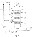
Figure 1 presents the process scheme for one embodiment of the invention (hydrotreating of renewable material), wherein the heat-sensitive feedstock is fed to a hydrotreatment reactor comprising in series three reaction zones, each zone containing one catalyst bed. -
Figure 2 presents a detail offigure 1 . -
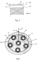
Figure 3 shows a cold feed distributor. -
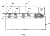
Figure 4 presents a side-view of an operating cold feed distributor. -
Figure 1 shows a hydrotreating reactor (12), which in this instance comprises three reaction zones (13C), (13B) and (13A), of which each contains a hydrotreating catalyst arranged to a catalyst bed. A liquid feed comprising a feedstock comprising renewable starting materials, typically vegetable oil, is fed at temperature T1 through line (10) to feed inlet lines (10A), (10B) and (10C), where a part of the product recycle (hydrotreated product), recycled as dilution through the recycling line (16) and a heat exchanger (15), is combined with the liquid feed. The diluted and heated liquid feed is fed at temperature T2 to the hydrotreating reactor (12) at feed inlets F1, F2 and F3 to the three reaction zones (13C), (13B) and (13A) using cold feed distributors. The reactor (12) comprises conventional distributors (not shown in the Figure) above each cold feed distributor. (Detail A ofreaction zone 13C where cold feed distributor (21) is shown is illustrated inFigure 2 ). At least part of the product recycle in line (16), optionally comprising the diluted and heated liquid feed is fed at temperature T2 to the hydrotreating reactor (12) at inlet F4 using a conventional distributor (not shown in the figure). The temperature of the recycling line (16) is set with the help of a heat exchanger (15). With the dilution stream of recycling line (16) the liquid feed (10) is effectively diluted and heated. Hydrogen (H2) containing gas (17) is fed to the recycling line (16) and the hydrogen containing dilution stream (11) is fed to the hydrotreating reactor (12) at temperature T2 and introduced to the reactor at feed inlet F4. Optionally a part of the liquid feed (10) may be introduced to the hydrogen containing dilution stream (11). Similarly the hydrogen feed (17) can be arranged to be introduced to the reactor together with the feed inlets F1, F2 and F3. (Not shown in the figure.) The hydrotreated product is withdrawn using line (14) at the temperature T3. - According to the
Figure 1 at least a significant portion or preferably all liquid feed is fed to the hydrotreating reactor directly to the hydrotreatment reaction zones through the feed inlets F1, F2 and F3 on the side of the reactor (12) and to the catalyst beds using the cold feed distributors. -
Figure 2 shows detail A ofFigure 1 , describing in reactor (12) a hydrotreatment zone (13C) to which a liquid feed is introduced into the catalyst bed (22) with a feed inlet F3 using a cold feed distributor (21) arranged on top of the catalyst bed (22). -
Figure 3 shows in detail a cross-section of a suitable cold feed distributor (21) and in this particular embodiment a ring distributor, to be installed in a reactor (12). The ring distributor (21) comprises a sufficient amount of, at least two and typically 6 distributor units (23) that are interconnected with each other with a pipe arrangement (24). Suitable said pipe arrangement is a feed ring/pipe. Said distributor units (23) comprise a space (26) limited with a wall (27). Said distributor units (23) are located on a circle (28) and preferably at least one of the distributor units (23) is located in the middle of the circle (28). Said distributor units (23) are located essentially in the same cross-section. Said ring distributor (21) further comprises at least one means (29) for feeding the liquid feed to the distributor units (23), said means being interconnected with said pipe arrangement (24) and a connection (30). Said distributor units (23) are advantageously manufactured from screen type plate that provides maximal flow area combined with even and stable flow to each direction. Said distributor units have preferably a ring-shaped structure, which enables simultaneous flow coming from above also through their openings. The parts of the distributor may be sufficiently connected to each other e.g. with flanged connections (not shown) so that that they are easily dismantled and removed if needed. - If needed the distributor units can be filled e.g. with active grading catalyst or be fully located within such layer to control the possible impurities in the flow to be distributed.
-
Figure 4 shows as side-view the operation of the cold feed distributor (21). The liquid feed (10) optionally comprising product recycled is fed to the ring distributor (21) and divided using pipe arrangement (24) to each distributor unit (23A), (23B) and (23C), and from the distributor units to the surrounding reactor space and catalyst bed, a stream (11) containing hydrogen and the diluting stream or reaction mixture from the previous catalyst bed is passed from a conventional distributor (not shown in the Figure) above the cold feed distributor (21) and to the catalyst bed (22). - It was surprisingly found that when feeding a heat-sensitive feedstock to a fixed-bed reactor system undesired thermal side-reactions occurring in the reactor before the heat-sensitive feedstock is allowed to get into contact with the active catalyst bed can be completely avoided or their extent can at least be significantly decreased to an acceptable level by using the method and arrangement according to the invention wherein the residence time is decreased significantly.
- The method according to the invention for feeding heat-sensitive feedstocks to a fixed-bed reactor system comprises the steps where a dilution stream comprising at least part of a product recycle is introduced to a fixed-bed reactor system comprising at least one fixed-bed reactor comprising at least one reaction zone having at least one catalyst bed and said reaction zone comprising a cold feed distributor arranged on top of each catalyst bed and a conventional distributor arranged above each cold feed distributor, and means for product recycle, said dilution stream being introduced at the top of the fixed-bed reactor to the conventional distributor, and a liquid feed comprising the heat-sensitive feedstock is introduced to the fixed-bed reactor to each reaction zone using the cold feed distributor(s). The temperature of said liquid feed is high enough to allow suitable transport of it to the reactor system, i.e. the viscosity of the feed material must be appropriate, but simultaneously the temperature is as low as possible to avoid side-reactions. During start-up any suitable hydrocarbon can be used as the product recycle until the actual product recycle is available. The dilution stream comprising at least part of the product recycle, or a reaction mixture obtained as effluent from an upper reaction zone (and catalyst bed) in the case the reactor system contains more than one reaction zones, is passed from the conventional distributor on the cold feed distributor whereby the liquid feed is rapidly mixed with the product recycle or reaction mixture and thus heated substantially to the desired reaction temperature and simultaneously passed to the active catalyst bed where the reaction is realized.
- The fixed-bed reactor comprises more than one reaction zone, the reaction zones being preferably in series.
- The arrangement according to the invention for feeding heat-sensitive feedstocks to a fixed-bed reactor system comprises a fixed-bed reactor comprising at least one reaction zone, suitably three reaction zones and each zones having at least one catalyst bed and each of the reaction zones comprising a cold feed distributor arranged on top of each catalyst bed and a conventional distributor arranged above each cold feed distributor, and means for product recycle.
- Said fixed-bed reactor system further comprises means for feeding the dilution stream (product recycle), optionally means for feeding gaseous component(s) and optionally means for feeding part of the liquid feed to the dilution stream to the feed inlet at the top of the fixed-bed reactor, optional means for feeding gaseous component(s) to one or more liquid feed inlets on the side of the fixed-bed reactor, means (preferably a recycle line) for recycling the reactor product to one or more feed inlets to each reaction zone to each catalyst bed, means for feeding liquid feed to one or more feed inlets, preferably to feed inlets on the side of the fixed-bed reactor to the cold feed distributors and at least one heat exchanging device in the recycle line for setting the temperature of the recycle product.
- The cold feed distributor may be any feed distributor which can be arranged on top of a catalyst bed. This means that the cold feed distributor is arranged as close as technically possible on the catalyst bed or partly embedded in the catalyst bed. The cold feed distributor is a short residence time distributor which provides immediate and even distribution of the feed. A ring distributor as described in
Figure 3 is an example of a suitable cold feed distributor. - The conventional distributor may be any distributor known in the art which provides longer residence times. Examples of suitable conventional distributors are bubble cap trays, nozzle trays and the like.
- A cold feed distributor is used for introducing the liquid feed to a reaction zone and directly to an active catalyst bed, particularly for ensuring simultaneously 1) even and rapid mixing of dilution stream or reaction mixture with the liquid feed and 2) for ensuring even and rapid distribution and entering of the liquid feed into the catalyst bed(s).
- The ring distributor, which is an example of a suitable cold feed distributor, comprises a sufficient amount, suitably at least two, preferably at least six distributor units interconnected with each other with a pipe arrangement, such as a feed ring/pipe, and at least one means for introducing the liquid feed into the distributor units, such as a feed pipe connected to the said pipe arrangement. The distributor units are located essentially in the same cross-section. The distributor units are advantageously manufactured from material comprising holes or openings, such as screen type plate, that allows and provides maximal flow area combined with even and stable flow to each direction. The distributor unit comprises a space limited by a wall and preferably said units have a ring-shaped structure, which enables simultaneous flow coming from above also through their openings. This arrangement minimizes the vertical flow obstacle and provides optimal mixing. Particularly the over-all flow profile is stabilized and very fast below the units.
- In the case gaseous component(s) such as hydrogen is used in the process, e.g. in hydrotreatment, said gaseous component(s) or part of it and at least part of the dilution stream are introduced at the top of the fixed-bed reactor system. Optionally said gaseous component(s) may also be introduced to one or more reaction zone(s) together with the liquid feed comprising the heat-sensitive feedstock using the cold feed distributors. Hydrogen refers here to hydrogen or any gas containing hydrogen.
- Liquid feed comprising the heat-sensitive feedstock is introduced to the fixed-bed reactor to each reaction zone and to the active catalyst bed using the cold feed distributor(s) arranged on the top of each catalyst bed.
- Said liquid feed has a temperature typically of at least ambient temperature (20-250°C), suitably from at least 60°C to 240°C.
- Said liquid feed comprising the heat-sensitive feedstock may comprise optional diluents, optionally part of the hot dilution stream and optionally gaseous component(s). The optional diluents may comprise any inert diluents suitably used in the intended reaction, such as hydrocarbons and the like.
The liquid feed, which comprises the heat-sensitive feedstock, optional diluents, optionally part of the hot dilution stream and optionally gaseous component(s), is introduced to each catalyst bed using the cold feed distributors. The dilution stream introduced to the reactor at the top of it and comprising at least part of a product recycle, or a reaction mixture obtained as effluent from an upper catalyst bed, both obtained/flowing from a conventional distributor arranged above the cold feed distributor is mixed with the liquid feed, which is rapidly heated whereby the temperature of the liquid feed is raised to the level required for effecting the reaction and simultaneously passed to the active catalyst bed. This reduces the residence time significantly. The heat-sensitive feed is maintained at this higher temperature for a very short time before the actual reaction occurs and thus essentially no or almost no adverse thermal side-reactions can occur. The residence time is less than 10 s, preferably 2-5 s and more preferably 1-2 s. - The temperature of the liquid feed, before entering the cold feed distributor and getting in contact with the active catalyst bed, depends on the nature of the feedstock. Suitably it is selected to be close to the temperature required in the reaction zone but lower than a temperature in which adverse side-reactions will occur.
- Before entering the reactor, the liquid feed is preferably heated with the dilution stream comprising the product recycle by mixing the liquid feed with the dilution stream having a temperature of 50 - 340 °C higher than the temperature of the liquid feed, to achieve the desired temperature, preferably between 60 and 240°C, particularly preferably between 150 and 220°C, whereby the dilution stream comprising the product recycle acts as a diluent and heats the liquid feed. Preferably a dilution stream having a temperature between 280 and 450°C, preferably between 300 and 350°C is used.
- According to a preferred embodiment of the invention the liquid feed is diluted and heated in at least one step, preferably in two to five steps, particularly preferably in two steps. The proportion of the dilution in the steps may vary in a ratio from 10:100 to 5000:100 (diluent:fresh feed). Preferably the feed is diluted in the first step with a diluent in a ratio from 0.1:1 to 5:1 (diluent:fresh feed) per weight. In the second step the liquid feed is then diluted with a diluent from 0.1:1 to 50:1 (diluent:fresh feed) per weight.
- As one embodiment of the invention, a method for feeding heat-sensitive feedstock comprising fatty acids and/or derivatives thereof to a hydrotreating reactor system for producing paraffinic hydrocarbons (n-paraffins) from renewable sources is presented in the following. The obtained hydrocarbons can be used as a hydrocarbon fuel or they can be converted into hydrocarbon fuels, for example by a further isomerization step resulting in iso-paraffins. Said method involves treating the feedstock with hydrogen in the presence of a catalyst whereby fatty acids and/or derivatives thereof are hydrodeoxygenated and/hydrogenated to form hydrocarbons.
- Said method for feeding heat-sensitive feedstock to a fixed-bed reactor system comprises the steps, where
- a) a dilution stream comprising at least part of a product recycle and hydrogen and having a temperature between 280 and 450°C, preferably between 300 and 350°C is introduced to a fixed-bed hydrotreating reactor system comprising at least one fixed-bed hydrotreating reactor comprising at least one reaction zone having at least one hydrotreating catalyst bed and said reaction zone comprising a cold feed distributor arranged on top of each catalyst bed and a conventional distributor arranged above each cold feed distributor, and means for product recycle, said dilution stream being introduced at the top of the fixed-bed reactor to the conventional distributor, and a liquid feed comprising the heat-sensitive feedstock is introduced to the fixed-bed reactor, and
- b) a liquid feed having a temperature between 60 and 240°C, preferably between 150 and 220°C and comprising fatty acids and/or derivatives thereof and optional diluents is introduced to the fixed-bed reactor to each reaction zone using the cold feed distributor(s), whereby the liquid feed is mixed with the dilution stream or reaction mixture and heated to 250- 350°C, preferably 280-320°C and passed to the catalyst bed where the hydrodeoxygenation and/or hydrogenation reaction is effected in the presence of hydrogen.
- Then the liquid hydrotreated product is separated.
- In the hydrotreating reaction known hydrogenation catalysts containing metals from Group VIII and/or VIB of the Periodic System may be used. Preferably, the hydrogenation catalysts are supported Pd, Pt, Ni, NiMo or a CoMo catalysts, the support being alumina and/or silica. The pressure may be varied between 2 and 15 MPa, and LHSV may range from 0.1 to 10 h-1 and H2 feed from 50 to 2000 l/l.
- When the liquid feed is introduced to each hydrotreating catalyst bed using the cold feed distributors arranged on top of each catalyst bed, the feed is rapidly heated to the temperature required for effecting the hydrotreatment reactions to happen in the presence of hydrogen. The duration of this heating step is so short that substantially no adverse thermal side-reactions can occur before the feedstock is hydrotreated.
- The feedstock is maintained at the hydrotreating temperature of 250-350°C only for a very short time before the actual hydrotreatment reactions start and thus essentially no adverse thermal reactions can occur. The residence time is less than 10 s, preferably 2-5 s and more preferably 1-2 s.
- The heat-sensitive feedstock comprising fatty acids and/or derivatives thereof is heated if necessary, to a temperature typically of at least ambient temperature (20°C or higher) required to obtain a liquid feed, i.e. in a form where it can be pumped. This temperature is highly dependent of the chemical composition of the feedstock. The liquid feed may optionally be diluted with diluents such as hydrocarbons if desired. The diluents may be recycled hydroteated products, recycled hydrotreated and isomerized products or a fresh hydrocarbon stream of any origin or any combination thereof. Suitably diesel range hydrocarbon fractions may be used as diluents.
- The hydrogenation and hydrodeoxygenation of fatty acid substances to n-paraffins is a highly exothermic reaction. The heat thus produced can be used for heating the liquid feed by recycling the hydrotreated product to liquid feed.
- Said feedstock, may comprise bio oil and/or fat originating from renewable sources, such as fats and oils from plants and/or animals and/or fish and compounds derived from them. Suitable bio oils are plant and vegetable oils and fats, animal fats, fish oils, and any mixtures thereof containing fatty acids and/or fatty acid esters. Examples of said materials are wood-based and other plant-based and vegetable-based fats and oils such as rapeseed oil, colza oil, canola oil, tall oil, sunflower oil, soybean oil, hempseed oil, olive oil, linseed oil, mustard oil, palm oil, peanut oil, castor oil, coconut oil, as well as fats contained in plants bred by means of gene manipulation, animal-based fats such as lard, tallow, train oil, and fats contained in milk, as well as recycled fats of the food industry and mixtures of the above. In some cases the feedstock, such as crude plant oil or animal fat, contains high impurity content and thus the feedstock is preferably purified using suitable pretreatment steps before introducing it to the hydrotreating step.
- Typically a bio oil or fat comprised in the feedstock comprises C12 - C24 fatty acids, derivatives thereof such as anhydrides or esters of fatty acids as well as triglycerides of fatty acids or combinations of thereof. The fatty acids or fatty acid derivatives, such as esters may be produced via hydrolysis of bio oils or by their fractionalization or transesterification reactions of triglycerides. The basic structural unit of a typical plant or vegetable or animal oil/fat useful as the feedstock is a triglyceride.
- The invention provides several significant advantages over the state of the art. In the method according to the invention the formation of heat-induced side-reaction products before contacting the feed with the active catalyst bed can be avoided or at least significantly decreased. The feed having a lower temperature is passed very rapidly to the active catalyst bed and simultaneously when entering the catalyst bed it is heated to the actual reaction temperature whereby the desired reactions start to occur. This decreases the residence times to a significant extent.
- The temperatures and the proportions of the product recycle can be optimised within the scope of the invention. A person skilled in the art is capable of optimising the temperatures and amounts of the dilution stream in the liquid feed and the dilution stream at the top of the reactor to achieve the temperatures of the invention.
- The effect of residence time is illustrated in the following example.
- Thermal stability of purified rapeseed oil (RSO) was tested. Purified rapeseed oil was heated in a container to either 200 °C or 300 °C. RSO was maintained at the final temperature for a specified time and the formation of oligomerization/polymerization products was studied. Samples of heated RSO were taken at 0 h when maximum temperature was reached, at 5 h, 22 h and finally when RSO again reached ambient temperature (25 °C) after cooling. The amount of triglycerides and oligomerisation/polymerization products was analysed using gel permeation chromatography.
- Table 1 below shows that almost no oligomerisation/polymerization occured when RSO was heated from 25 to 200 °C. Even, after 22 h at 200 °C virtually no oligomerisation/polymerization was observed. When RSO was heated to 300 °C the oligomerisation/polymerization started immediately and after 5 hours at 300 °C already 16 % of the feedstock was oligomerised/polymerized. In the case RSO was maintained for a longer period of at a temperature of 300 °C, more oligomerisation/polymerization occured. The results of the tests are provided in following Table 1.
Table 1. Temperature (°C) Residence time (hours) RSO glycerides (%) Oligomerisation products (%) Purified rapeseed oil 25 0 99 0.3 Stability test 200°C 25 → 200 1 98 1 200 5 97 2 200 22 97 2 200 → 25 25 97 2 25 → 300 1 95 3 300 5 78 16
Claims (9)
- An arrangement for feeding heat-sensitive feedstock to a fixed-bed reactor system wherein said arrangement comprises means (16) for product recycle and a fixed-bed reactor system comprising a fixed-bed reactor comprising more than one reaction zone (13C, 13B, 13A) having at least one catalyst bed (22) and each reaction zone (13C, 13B, 13A) comprising a cold feed distributor (21) arranged on top of each catalyst bed (22) and a conventional distributor arranged above each cold feed distributor (21), means (10) for feeding liquid feed to feed inlets (F1, F2, F3) connected to the cold feed distributors, and means for feeding a dilution stream to a feed inlet (F4) at the top of the reactor.
- The arrangement according to claim 1, wherein said fixed-bed reactor system comprises at least one means selected from means (17) for feeding gaseous component(s), means for feeding part of a liquid feed comprising the heat-sensitive feedstock to the dilution stream to the feed inlet (F4) at the top of the fixed-bed reactor, means for feeding gaseous component(s) to one or more liquid feed inlets (F1, F2, F3) on the side of the fixed-bed reactor, and means (16) for recycling the reactor product to one or more feed inlets (F1, F2, F3) to each reaction zone (13C, 13B, 13A) to each catalyst bed (22).
- A method for feeding heat-sensitive feedstock to a fixed-bed reactor system wherein said fixed-bed reactor system comprises means (16) for product recycle and a fixed-bed reactor comprising more than one reaction zone (13C, 13B, 13A) having at least one catalyst bed (22) and each reaction zone comprising a cold feed distributor (21) arranged on top of each catalyst bed (22) and a conventional distributor arranged above each cold feed distributor (21), and
wherein a dilution stream comprising at least part of the product recycle is introduced to the fixed-bed reactor system at the top of the fixed-bed reactor and to a conventional distributor, and
wherein a liquid feed comprising the heat-sensitive feedstock is introduced to the fixed-bed reactor system to each reaction zone with the cold feed distributor(s) - The method according to claim 3, wherein the temperature of the liquid feed is from 20 to 250 °C, preferably from 60 to 240 °C.
- The method according to claim 3 or 4, wherein the liquid feed is mixed with part of said dilution stream having a temperature of 50 - 340 °C higher than the temperature of the liquid feed, before introducing to each reaction zone.
- The method according to any one of claims 3 - 5, wherein the temperature of said dilution stream is between 280 and 450 °C.
- The method according to any one of claims 3 - 6, wherein at least one gaseous component is introduced to said dilution stream and then to the top of the fixed-bed reactor.
- The method according to any one of claims 3 - 7, wherein at least one gaseous component is introduced to at least one reaction zone together with the liquid feed.
- The method according to claim 7 or 8, wherein the gaseous component is hydrogen or a gas containing hydrogen.
Priority Applications (4)
| Application Number | Priority Date | Filing Date | Title |
|---|---|---|---|
| EP11151226.5A EP2476482B2 (en) | 2011-01-18 | 2011-01-18 | Method and arrangement for feeding heat-sensitive materials to fixed-bed reactors |
| ES11151226T ES2626658T5 (en) | 2011-01-18 | 2011-01-18 | Method and arrangement for feeding heat sensitive materials to fixed bed reactors |
| US13/350,578 US9352292B2 (en) | 2011-01-18 | 2012-01-13 | Method and arrangement for feeding heat-sensitive materials to fixed-bed reactors |
| PCT/FI2012/050039 WO2012098293A1 (en) | 2011-01-18 | 2012-01-18 | Method and arrangement for feeding heat-sensitive materials to fixed-bed reactors |
Applications Claiming Priority (1)
| Application Number | Priority Date | Filing Date | Title |
|---|---|---|---|
| EP11151226.5A EP2476482B2 (en) | 2011-01-18 | 2011-01-18 | Method and arrangement for feeding heat-sensitive materials to fixed-bed reactors |
Publications (3)
| Publication Number | Publication Date |
|---|---|
| EP2476482A1 EP2476482A1 (en) | 2012-07-18 |
| EP2476482B1 EP2476482B1 (en) | 2017-03-01 |
| EP2476482B2 true EP2476482B2 (en) | 2020-05-13 |
Family
ID=44063332
Family Applications (1)
| Application Number | Title | Priority Date | Filing Date |
|---|---|---|---|
| EP11151226.5A Active EP2476482B2 (en) | 2011-01-18 | 2011-01-18 | Method and arrangement for feeding heat-sensitive materials to fixed-bed reactors |
Country Status (4)
| Country | Link |
|---|---|
| US (1) | US9352292B2 (en) |
| EP (1) | EP2476482B2 (en) |
| ES (1) | ES2626658T5 (en) |
| WO (1) | WO2012098293A1 (en) |
Families Citing this family (12)
| Publication number | Priority date | Publication date | Assignee | Title |
|---|---|---|---|---|
| US7722832B2 (en) | 2003-03-25 | 2010-05-25 | Crystaphase International, Inc. | Separation method and assembly for process streams in component separation units |
| FR3039160B1 (en) * | 2015-07-24 | 2017-07-28 | Ifp Energies Now | PROCESS FOR HYDROTREATING RENEWABLE MATERIALS WITH AN OPTIMIZED GAS RECYCLE |
| US10744426B2 (en) | 2015-12-31 | 2020-08-18 | Crystaphase Products, Inc. | Structured elements and methods of use |
| US10054140B2 (en) | 2016-02-12 | 2018-08-21 | Crystaphase Products, Inc. | Use of treating elements to facilitate flow in vessels |
| CN111375350B (en) * | 2018-12-30 | 2021-10-08 | 中国石油化工股份有限公司 | Upflow reactor and its use |
| EP4076719A1 (en) | 2019-12-20 | 2022-10-26 | Crystaphase Products Inc. | Resaturation of gas into a liquid feedstream |
| JP2023541252A (en) | 2020-09-09 | 2023-09-29 | クリスタフェーズ・プロダクツ・インコーポレーテッド | Process vessel entry zone |
| EP4337376A1 (en) | 2021-05-13 | 2024-03-20 | Shell Internationale Research Maatschappij B.V. | Process for hydroprocessing materials from renewable sources |
| CN116020350B (en) * | 2021-10-26 | 2025-11-25 | 中国石油化工股份有限公司 | A reactor, a system, and a method for synthesizing carbonates. |
| CN116836725B (en) * | 2023-06-16 | 2025-07-11 | 黑龙江莱睿普思环境科技发展有限公司 | Hydrogenation reactor for refining waste mineral oil |
| CN117654380B (en) * | 2024-02-02 | 2024-04-23 | 山东东方宏业化工有限公司 | Catalytic hydrocracking system for comprehensively recycling waste organic matter pyrolysis gas |
| CN119406324B (en) * | 2024-10-28 | 2025-11-07 | 浙江大学衢州研究院 | Reverse/cross-flow hydrogenation reaction device and application thereof |
Citations (5)
| Publication number | Priority date | Publication date | Assignee | Title |
|---|---|---|---|---|
| WO1997046303A1 (en) † | 1996-06-04 | 1997-12-11 | Fluor Corporation | Reactor distribution apparatus and quench zone mixing apparatus |
| WO2002070120A1 (en) † | 2001-03-01 | 2002-09-12 | Shell Internationale Research Maatschappij B.V. | Self-supporting reactor internal |
| EP1741768A1 (en) † | 2005-07-04 | 2007-01-10 | Neste Oil OYJ | Process for the manufacture of diesel range hydrocarbons |
| US20090082606A1 (en) † | 2007-09-20 | 2009-03-26 | Marker Terry L | Production of Diesel Fuel from Biorenewable Feedstocks |
| EP2226375A1 (en) † | 2009-03-04 | 2010-09-08 | PCK Raffinerie GmbH | Process for the continuous hydrogenation of triglyceride containing raw materials |
Family Cites Families (12)
| Publication number | Priority date | Publication date | Assignee | Title |
|---|---|---|---|---|
| EP0306164B1 (en) | 1987-08-13 | 1992-10-14 | Uop | Hydrogenating a temperature sensitive hydrocarbonaceous waste stream |
| US4808350A (en) * | 1987-08-26 | 1989-02-28 | The Dow Chemical Company | Liquid distributor apparatus for high turndown ratios and minimum fouling |
| US7074372B2 (en) | 2003-05-16 | 2006-07-11 | Exxonmobil Research And Engineering Company | Multiphase mixing device with improved quench injection for inducing rotational flow |
| US7473811B2 (en) | 2003-11-13 | 2009-01-06 | Neste Oil Oyj | Process for the hydrogenation of olefins |
| FR2883200B1 (en) * | 2005-03-17 | 2007-05-11 | Inst Francais Du Petrole | DEVICE FOR MIXING AND DISTRIBUTING A GAS AND A LIQUID BEFORE A GRANULAR BED |
| MX2008000259A (en) | 2005-07-04 | 2008-03-11 | Neste Oil Oyj | Process for the manufacture of diesel range hydrocarbons. |
| PL1741767T3 (en) | 2005-07-04 | 2015-12-31 | Neste Oil Oyj | Process for the manufacture of diesel range hydrocarbons |
| US8022258B2 (en) | 2005-07-05 | 2011-09-20 | Neste Oil Oyj | Process for the manufacture of diesel range hydrocarbons |
| CN101448919A (en) * | 2006-04-21 | 2009-06-03 | 国际壳牌研究有限公司 | Process for hydrogenating aromatics in a hydrocarbon feed containing thiopheneic compounds |
| US7803334B1 (en) * | 2006-07-11 | 2010-09-28 | Uop Llc | Apparatus for hydrocracking a hydrocarbon feedstock |
| FR2913024B1 (en) | 2007-02-27 | 2012-07-27 | Total France | METHOD FOR HYDROPROCESSING A GAS FUEL LOAD, HYDROTREATING UNIT FOR CARRYING OUT SAID METHOD, AND CORRESPONDING HYDROREFINING UNIT |
| JP5276098B2 (en) * | 2007-06-21 | 2013-08-28 | ビーエーエスエフ ソシエタス・ヨーロピア | Reactor for carrying out liquid-phase and gas-phase three-phase reactions on a catalyst bed |
-
2011
- 2011-01-18 EP EP11151226.5A patent/EP2476482B2/en active Active
- 2011-01-18 ES ES11151226T patent/ES2626658T5/en active Active
-
2012
- 2012-01-13 US US13/350,578 patent/US9352292B2/en active Active
- 2012-01-18 WO PCT/FI2012/050039 patent/WO2012098293A1/en not_active Ceased
Patent Citations (5)
| Publication number | Priority date | Publication date | Assignee | Title |
|---|---|---|---|---|
| WO1997046303A1 (en) † | 1996-06-04 | 1997-12-11 | Fluor Corporation | Reactor distribution apparatus and quench zone mixing apparatus |
| WO2002070120A1 (en) † | 2001-03-01 | 2002-09-12 | Shell Internationale Research Maatschappij B.V. | Self-supporting reactor internal |
| EP1741768A1 (en) † | 2005-07-04 | 2007-01-10 | Neste Oil OYJ | Process for the manufacture of diesel range hydrocarbons |
| US20090082606A1 (en) † | 2007-09-20 | 2009-03-26 | Marker Terry L | Production of Diesel Fuel from Biorenewable Feedstocks |
| EP2226375A1 (en) † | 2009-03-04 | 2010-09-08 | PCK Raffinerie GmbH | Process for the continuous hydrogenation of triglyceride containing raw materials |
Also Published As
| Publication number | Publication date |
|---|---|
| WO2012098293A1 (en) | 2012-07-26 |
| EP2476482B1 (en) | 2017-03-01 |
| US20120184792A1 (en) | 2012-07-19 |
| US9352292B2 (en) | 2016-05-31 |
| EP2476482A1 (en) | 2012-07-18 |
| ES2626658T5 (en) | 2021-01-26 |
| ES2626658T3 (en) | 2017-07-25 |
Similar Documents
| Publication | Publication Date | Title |
|---|---|---|
| EP2476482B2 (en) | Method and arrangement for feeding heat-sensitive materials to fixed-bed reactors | |
| JP5914588B2 (en) | Process for continuous hydrogenation of raw materials containing triglycerides | |
| US11473018B2 (en) | Process for the manufacture of diesel range hydrocarbons | |
| US8912374B2 (en) | Process for producing paraffinic hydrocarbons | |
| EP1741767B2 (en) | Process for the manufacture of diesel range hydrocarbons | |
| EP2141217B1 (en) | Process for the manufacture of aviation fuel or blending stocks for aviation fuel of biological origin | |
| EP1741768A1 (en) | Process for the manufacture of diesel range hydrocarbons | |
| EP2612900B1 (en) | Method for producing renewable fuel using supercritical fluid | |
| AU2021327729B2 (en) | Process for hydrotreatment of materials from renewable sources | |
| CN102399567B (en) | Nickel and catalyst with base of molybdenum continuous hydrogenation is used to contain the raw-material method of triglyceride level | |
| US8734638B2 (en) | Ebullating bed methods for treatment of biocomponent feedstocks | |
| US20110098494A1 (en) | Method of hydrotreating feeds from renewable sources with indirect heating using a catalyst based on nickel and molybdenum having a particular atomic ratio | |
| US12203035B2 (en) | Process for the manufacture of diesel range hydrocarbons | |
| EP2756055B1 (en) | Renewable diesel refinery strategy | |
| RU2630774C1 (en) | Method for hydraulic processing of hydrocarbon raw materials | |
| EA051705B1 (en) | METHOD FOR HYDROTREATMENT OF LIQUID OIL FEEDSTOCK |
Legal Events
| Date | Code | Title | Description |
|---|---|---|---|
| PUAI | Public reference made under article 153(3) epc to a published international application that has entered the european phase |
Free format text: ORIGINAL CODE: 0009012 |
|
| 17P | Request for examination filed |
Effective date: 20110118 |
|
| AK | Designated contracting states |
Kind code of ref document: A1 Designated state(s): AL AT BE BG CH CY CZ DE DK EE ES FI FR GB GR HR HU IE IS IT LI LT LU LV MC MK MT NL NO PL PT RO RS SE SI SK SM TR |
|
| AX | Request for extension of the european patent |
Extension state: BA ME |
|
| 17Q | First examination report despatched |
Effective date: 20130301 |
|
| GRAP | Despatch of communication of intention to grant a patent |
Free format text: ORIGINAL CODE: EPIDOSNIGR1 |
|
| INTG | Intention to grant announced |
Effective date: 20160705 |
|
| RAP1 | Party data changed (applicant data changed or rights of an application transferred) |
Owner name: NESTE OYJ |
|
| GRAS | Grant fee paid |
Free format text: ORIGINAL CODE: EPIDOSNIGR3 |
|
| GRAJ | Information related to disapproval of communication of intention to grant by the applicant or resumption of examination proceedings by the epo deleted |
Free format text: ORIGINAL CODE: EPIDOSDIGR1 |
|
| GRAL | Information related to payment of fee for publishing/printing deleted |
Free format text: ORIGINAL CODE: EPIDOSDIGR3 |
|
| INTC | Intention to grant announced (deleted) | ||
| GRAR | Information related to intention to grant a patent recorded |
Free format text: ORIGINAL CODE: EPIDOSNIGR71 |
|
| GRAJ | Information related to disapproval of communication of intention to grant by the applicant or resumption of examination proceedings by the epo deleted |
Free format text: ORIGINAL CODE: EPIDOSDIGR1 |
|
| GRAR | Information related to intention to grant a patent recorded |
Free format text: ORIGINAL CODE: EPIDOSNIGR71 |
|
| GRAA | (expected) grant |
Free format text: ORIGINAL CODE: 0009210 |
|
| INTG | Intention to grant announced |
Effective date: 20170116 |
|
| AK | Designated contracting states |
Kind code of ref document: B1 Designated state(s): AL AT BE BG CH CY CZ DE DK EE ES FI FR GB GR HR HU IE IS IT LI LT LU LV MC MK MT NL NO PL PT RO RS SE SI SK SM TR |
|
| INTG | Intention to grant announced |
Effective date: 20170124 |
|
| REG | Reference to a national code |
Ref country code: GB Ref legal event code: FG4D |
|
| REG | Reference to a national code |
Ref country code: CH Ref legal event code: EP Ref country code: AT Ref legal event code: REF Ref document number: 870624 Country of ref document: AT Kind code of ref document: T Effective date: 20170315 |
|
| REG | Reference to a national code |
Ref country code: IE Ref legal event code: FG4D |
|
| REG | Reference to a national code |
Ref country code: DE Ref legal event code: R096 Ref document number: 602011035351 Country of ref document: DE |
|
| REG | Reference to a national code |
Ref country code: NL Ref legal event code: FP |
|
| REG | Reference to a national code |
Ref country code: SE Ref legal event code: TRGR |
|
| REG | Reference to a national code |
Ref country code: LT Ref legal event code: MG4D |
|
| REG | Reference to a national code |
Ref country code: AT Ref legal event code: MK05 Ref document number: 870624 Country of ref document: AT Kind code of ref document: T Effective date: 20170301 |
|
| REG | Reference to a national code |
Ref country code: ES Ref legal event code: FG2A Ref document number: 2626658 Country of ref document: ES Kind code of ref document: T3 Effective date: 20170725 |
|
| PG25 | Lapsed in a contracting state [announced via postgrant information from national office to epo] |
Ref country code: NO Free format text: LAPSE BECAUSE OF FAILURE TO SUBMIT A TRANSLATION OF THE DESCRIPTION OR TO PAY THE FEE WITHIN THE PRESCRIBED TIME-LIMIT Effective date: 20170601 Ref country code: HR Free format text: LAPSE BECAUSE OF FAILURE TO SUBMIT A TRANSLATION OF THE DESCRIPTION OR TO PAY THE FEE WITHIN THE PRESCRIBED TIME-LIMIT Effective date: 20170301 Ref country code: LT Free format text: LAPSE BECAUSE OF FAILURE TO SUBMIT A TRANSLATION OF THE DESCRIPTION OR TO PAY THE FEE WITHIN THE PRESCRIBED TIME-LIMIT Effective date: 20170301 Ref country code: GR Free format text: LAPSE BECAUSE OF FAILURE TO SUBMIT A TRANSLATION OF THE DESCRIPTION OR TO PAY THE FEE WITHIN THE PRESCRIBED TIME-LIMIT Effective date: 20170602 |
|
| PG25 | Lapsed in a contracting state [announced via postgrant information from national office to epo] |
Ref country code: LV Free format text: LAPSE BECAUSE OF FAILURE TO SUBMIT A TRANSLATION OF THE DESCRIPTION OR TO PAY THE FEE WITHIN THE PRESCRIBED TIME-LIMIT Effective date: 20170301 Ref country code: RS Free format text: LAPSE BECAUSE OF FAILURE TO SUBMIT A TRANSLATION OF THE DESCRIPTION OR TO PAY THE FEE WITHIN THE PRESCRIBED TIME-LIMIT Effective date: 20170301 Ref country code: BG Free format text: LAPSE BECAUSE OF FAILURE TO SUBMIT A TRANSLATION OF THE DESCRIPTION OR TO PAY THE FEE WITHIN THE PRESCRIBED TIME-LIMIT Effective date: 20170601 Ref country code: AT Free format text: LAPSE BECAUSE OF FAILURE TO SUBMIT A TRANSLATION OF THE DESCRIPTION OR TO PAY THE FEE WITHIN THE PRESCRIBED TIME-LIMIT Effective date: 20170301 |
|
| PG25 | Lapsed in a contracting state [announced via postgrant information from national office to epo] |
Ref country code: EE Free format text: LAPSE BECAUSE OF FAILURE TO SUBMIT A TRANSLATION OF THE DESCRIPTION OR TO PAY THE FEE WITHIN THE PRESCRIBED TIME-LIMIT Effective date: 20170301 Ref country code: SK Free format text: LAPSE BECAUSE OF FAILURE TO SUBMIT A TRANSLATION OF THE DESCRIPTION OR TO PAY THE FEE WITHIN THE PRESCRIBED TIME-LIMIT Effective date: 20170301 Ref country code: RO Free format text: LAPSE BECAUSE OF FAILURE TO SUBMIT A TRANSLATION OF THE DESCRIPTION OR TO PAY THE FEE WITHIN THE PRESCRIBED TIME-LIMIT Effective date: 20170301 Ref country code: CZ Free format text: LAPSE BECAUSE OF FAILURE TO SUBMIT A TRANSLATION OF THE DESCRIPTION OR TO PAY THE FEE WITHIN THE PRESCRIBED TIME-LIMIT Effective date: 20170301 |
|
| PG25 | Lapsed in a contracting state [announced via postgrant information from national office to epo] |
Ref country code: PL Free format text: LAPSE BECAUSE OF FAILURE TO SUBMIT A TRANSLATION OF THE DESCRIPTION OR TO PAY THE FEE WITHIN THE PRESCRIBED TIME-LIMIT Effective date: 20170301 Ref country code: IS Free format text: LAPSE BECAUSE OF FAILURE TO SUBMIT A TRANSLATION OF THE DESCRIPTION OR TO PAY THE FEE WITHIN THE PRESCRIBED TIME-LIMIT Effective date: 20170701 Ref country code: SM Free format text: LAPSE BECAUSE OF FAILURE TO SUBMIT A TRANSLATION OF THE DESCRIPTION OR TO PAY THE FEE WITHIN THE PRESCRIBED TIME-LIMIT Effective date: 20170301 Ref country code: PT Free format text: LAPSE BECAUSE OF FAILURE TO SUBMIT A TRANSLATION OF THE DESCRIPTION OR TO PAY THE FEE WITHIN THE PRESCRIBED TIME-LIMIT Effective date: 20170703 |
|
| REG | Reference to a national code |
Ref country code: DE Ref legal event code: R026 Ref document number: 602011035351 Country of ref document: DE |
|
| PLBI | Opposition filed |
Free format text: ORIGINAL CODE: 0009260 |
|
| REG | Reference to a national code |
Ref country code: FR Ref legal event code: PLFP Year of fee payment: 8 |
|
| PLAX | Notice of opposition and request to file observation + time limit sent |
Free format text: ORIGINAL CODE: EPIDOSNOBS2 |
|
| 26 | Opposition filed |
Opponent name: UPM-KYMMENE OY Effective date: 20171130 |
|
| PG25 | Lapsed in a contracting state [announced via postgrant information from national office to epo] |
Ref country code: DK Free format text: LAPSE BECAUSE OF FAILURE TO SUBMIT A TRANSLATION OF THE DESCRIPTION OR TO PAY THE FEE WITHIN THE PRESCRIBED TIME-LIMIT Effective date: 20170301 |
|
| PG25 | Lapsed in a contracting state [announced via postgrant information from national office to epo] |
Ref country code: SI Free format text: LAPSE BECAUSE OF FAILURE TO SUBMIT A TRANSLATION OF THE DESCRIPTION OR TO PAY THE FEE WITHIN THE PRESCRIBED TIME-LIMIT Effective date: 20170301 |
|
| PLBB | Reply of patent proprietor to notice(s) of opposition received |
Free format text: ORIGINAL CODE: EPIDOSNOBS3 |
|
| REG | Reference to a national code |
Ref country code: CH Ref legal event code: PL |
|
| PG25 | Lapsed in a contracting state [announced via postgrant information from national office to epo] |
Ref country code: LU Free format text: LAPSE BECAUSE OF NON-PAYMENT OF DUE FEES Effective date: 20180118 |
|
| REG | Reference to a national code |
Ref country code: IE Ref legal event code: MM4A |
|
| PG25 | Lapsed in a contracting state [announced via postgrant information from national office to epo] |
Ref country code: CH Free format text: LAPSE BECAUSE OF NON-PAYMENT OF DUE FEES Effective date: 20180131 Ref country code: LI Free format text: LAPSE BECAUSE OF NON-PAYMENT OF DUE FEES Effective date: 20180131 |
|
| PG25 | Lapsed in a contracting state [announced via postgrant information from national office to epo] |
Ref country code: IE Free format text: LAPSE BECAUSE OF NON-PAYMENT OF DUE FEES Effective date: 20180118 |
|
| PG25 | Lapsed in a contracting state [announced via postgrant information from national office to epo] |
Ref country code: MC Free format text: LAPSE BECAUSE OF FAILURE TO SUBMIT A TRANSLATION OF THE DESCRIPTION OR TO PAY THE FEE WITHIN THE PRESCRIBED TIME-LIMIT Effective date: 20170301 |
|
| APBM | Appeal reference recorded |
Free format text: ORIGINAL CODE: EPIDOSNREFNO |
|
| APBP | Date of receipt of notice of appeal recorded |
Free format text: ORIGINAL CODE: EPIDOSNNOA2O |
|
| APAH | Appeal reference modified |
Free format text: ORIGINAL CODE: EPIDOSCREFNO |
|
| REG | Reference to a national code |
Ref country code: DE Ref legal event code: R082 Ref document number: 602011035351 Country of ref document: DE Representative=s name: STRAUS, ALEXANDER, DIPL.-CHEM.UNIV. DR.PHIL., DE Ref country code: DE Ref legal event code: R082 Ref document number: 602011035351 Country of ref document: DE Representative=s name: 2K PATENT- UND RECHTSANWAELTE PARTNERSCHAFT MB, DE |
|
| PG25 | Lapsed in a contracting state [announced via postgrant information from national office to epo] |
Ref country code: MT Free format text: LAPSE BECAUSE OF NON-PAYMENT OF DUE FEES Effective date: 20180118 |
|
| APBU | Appeal procedure closed |
Free format text: ORIGINAL CODE: EPIDOSNNOA9O |
|
| PG25 | Lapsed in a contracting state [announced via postgrant information from national office to epo] |
Ref country code: TR Free format text: LAPSE BECAUSE OF FAILURE TO SUBMIT A TRANSLATION OF THE DESCRIPTION OR TO PAY THE FEE WITHIN THE PRESCRIBED TIME-LIMIT Effective date: 20170301 |
|
| PUAH | Patent maintained in amended form |
Free format text: ORIGINAL CODE: 0009272 |
|
| STAA | Information on the status of an ep patent application or granted ep patent |
Free format text: STATUS: PATENT MAINTAINED AS AMENDED |
|
| 27A | Patent maintained in amended form |
Effective date: 20200513 |
|
| AK | Designated contracting states |
Kind code of ref document: B2 Designated state(s): AL AT BE BG CH CY CZ DE DK EE ES FI FR GB GR HR HU IE IS IT LI LT LU LV MC MK MT NL NO PL PT RO RS SE SI SK SM TR |
|
| REG | Reference to a national code |
Ref country code: DE Ref legal event code: R102 Ref document number: 602011035351 Country of ref document: DE |
|
| PG25 | Lapsed in a contracting state [announced via postgrant information from national office to epo] |
Ref country code: HU Free format text: LAPSE BECAUSE OF FAILURE TO SUBMIT A TRANSLATION OF THE DESCRIPTION OR TO PAY THE FEE WITHIN THE PRESCRIBED TIME-LIMIT; INVALID AB INITIO Effective date: 20110118 |
|
| PG25 | Lapsed in a contracting state [announced via postgrant information from national office to epo] |
Ref country code: CY Free format text: LAPSE BECAUSE OF FAILURE TO SUBMIT A TRANSLATION OF THE DESCRIPTION OR TO PAY THE FEE WITHIN THE PRESCRIBED TIME-LIMIT Effective date: 20170301 Ref country code: MK Free format text: LAPSE BECAUSE OF NON-PAYMENT OF DUE FEES Effective date: 20170301 |
|
| REG | Reference to a national code |
Ref country code: SE Ref legal event code: RPEO |
|
| PG25 | Lapsed in a contracting state [announced via postgrant information from national office to epo] |
Ref country code: AL Free format text: LAPSE BECAUSE OF FAILURE TO SUBMIT A TRANSLATION OF THE DESCRIPTION OR TO PAY THE FEE WITHIN THE PRESCRIBED TIME-LIMIT Effective date: 20170301 |
|
| REG | Reference to a national code |
Ref country code: NL Ref legal event code: FP |
|
| REG | Reference to a national code |
Ref country code: ES Ref legal event code: DC2A Ref document number: 2626658 Country of ref document: ES Kind code of ref document: T5 Effective date: 20210126 |
|
| P01 | Opt-out of the competence of the unified patent court (upc) registered |
Effective date: 20230525 |
|
| REG | Reference to a national code |
Ref country code: DE Ref legal event code: R082 Ref document number: 602011035351 Country of ref document: DE Representative=s name: STRAUS, ALEXANDER, DIPL.-CHEM.UNIV. DR.PHIL., DE |
|
| PGFP | Annual fee paid to national office [announced via postgrant information from national office to epo] |
Ref country code: GB Payment date: 20251204 Year of fee payment: 16 |
|
| PGFP | Annual fee paid to national office [announced via postgrant information from national office to epo] |
Ref country code: FI Payment date: 20251230 Year of fee payment: 16 |
|
| PGFP | Annual fee paid to national office [announced via postgrant information from national office to epo] |
Ref country code: NL Payment date: 20251215 Year of fee payment: 16 Ref country code: FR Payment date: 20251222 Year of fee payment: 16 |
|
| PGFP | Annual fee paid to national office [announced via postgrant information from national office to epo] |
Ref country code: SE Payment date: 20251210 Year of fee payment: 16 |
|
| PGFP | Annual fee paid to national office [announced via postgrant information from national office to epo] |
Ref country code: ES Payment date: 20260206 Year of fee payment: 16 |
|
| PGFP | Annual fee paid to national office [announced via postgrant information from national office to epo] |
Ref country code: DE Payment date: 20251203 Year of fee payment: 16 |
|
| PGFP | Annual fee paid to national office [announced via postgrant information from national office to epo] |
Ref country code: BE Payment date: 20260106 Year of fee payment: 16 Ref country code: IT Payment date: 20251219 Year of fee payment: 16 |