EP2476350A1 - Plant holder - Google Patents
Plant holder Download PDFInfo
- Publication number
- EP2476350A1 EP2476350A1 EP11150984A EP11150984A EP2476350A1 EP 2476350 A1 EP2476350 A1 EP 2476350A1 EP 11150984 A EP11150984 A EP 11150984A EP 11150984 A EP11150984 A EP 11150984A EP 2476350 A1 EP2476350 A1 EP 2476350A1
- Authority
- EP
- European Patent Office
- Prior art keywords
- plant holder
- tray
- holder according
- recess wall
- recess
- Prior art date
- Legal status (The legal status is an assumption and is not a legal conclusion. Google has not performed a legal analysis and makes no representation as to the accuracy of the status listed.)
- Withdrawn
Links
- 235000013361 beverage Nutrition 0.000 claims abstract description 10
- 235000013305 food Nutrition 0.000 claims abstract description 10
- 230000035622 drinking Effects 0.000 description 1
- 238000012986 modification Methods 0.000 description 1
- 230000004048 modification Effects 0.000 description 1
Images


Classifications
-
- A—HUMAN NECESSITIES
- A47—FURNITURE; DOMESTIC ARTICLES OR APPLIANCES; COFFEE MILLS; SPICE MILLS; SUCTION CLEANERS IN GENERAL
- A47G—HOUSEHOLD OR TABLE EQUIPMENT
- A47G7/00—Flower holders or the like
- A47G7/02—Devices for supporting flower-pots or cut flowers
- A47G7/04—Flower tables; Stands or hangers, e.g. baskets, for flowers
- A47G7/044—Hanging flower-pot holders, e.g. mounted on walls, balcony fences or the like
-
- A—HUMAN NECESSITIES
- A47—FURNITURE; DOMESTIC ARTICLES OR APPLIANCES; COFFEE MILLS; SPICE MILLS; SUCTION CLEANERS IN GENERAL
- A47B—TABLES; DESKS; OFFICE FURNITURE; CABINETS; DRAWERS; GENERAL DETAILS OF FURNITURE
- A47B5/00—Suspended or hinged panels forming a table; Wall tables
-
- A—HUMAN NECESSITIES
- A47—FURNITURE; DOMESTIC ARTICLES OR APPLIANCES; COFFEE MILLS; SPICE MILLS; SUCTION CLEANERS IN GENERAL
- A47B—TABLES; DESKS; OFFICE FURNITURE; CABINETS; DRAWERS; GENERAL DETAILS OF FURNITURE
- A47B96/00—Details of cabinets, racks or shelf units not covered by a single one of groups A47B43/00 - A47B95/00; General details of furniture
- A47B96/02—Shelves
Definitions
- the invention relates to a plant holder configured to be placed on a balustrade.
- the plant holder comprises a ground box configured to in use hold ground in which a plant is placed and a balustrade receiving recess configured to in use engage the balustrade such that the plant holder is supported by the balustrade.
- EP1198984 relates to a multifunctional flower box.
- the flower box is "multifunctional" because the flower box provides a structure designed for being hung in various ways.
- the plant holder according the invention is configured to be placed on a balustrade and comprises a ground box configured to in use hold ground in which a plant is placed, a balustrade receiving recess configured to in use engage the balustrade such that the plant holder is supported by the balustrade, and a tray configured to in use hold a consumer good, such as food or beverage.
- the plant holder according the invention allows the user to place a consumer good, such as food or beverage, on the tray while standing or sitting near the plant holder supported by the balustrade. This means that when for example standing or sitting on a balcony, the user can on nice summer morning place a cup of coffee on the tray while enjoying the view of a beautiful plant held by the ground box.
- a consumer good such as food or beverage
- the flower box disclosed in EP1198984 comprises a tray portion.
- Said tray portion is an element which covers several components located between the underside of the flower box and the tray portion. It will be clear that a user will not be able to place a consumer good on the tray portion of EP1198984 .
- EP1198984 also discloses a configuration of two interconnected flower boxes. It will be clear that the tray of the plant holder according the invention is completely different from the flower box of EP1198984 . One places ground in the flower box of EP1198984 . The user can place a consumer good on the tray of the plant holder according to the invention. Placing a item in the flower box of EP1198984 requires a totally different movement of the user standing and even more when sitting on a balcony than placing an item on the tray of the plant holder according the invention. Furthermore, the user will not place a consumer good, such as food and beverage in the flower box of EP1198984 , because a flower box is not considered as being hygienic.
- the tray comprises a support surface for supporting the consumer good and is configured such that in use the consumer good can be moved towards the support surface in a direction having an angle ⁇ being smaller than or around 20° relative to the support surface. This allows the user standing or sitting near the balustrade to conveniently place a consumer good, such as a cup of coffee, on the tray.
- the angle ⁇ may be smaller than or around 10°.
- the support surface of the tray is configured to extend substantially horizontal when the plant holder is supported by the balustrade.
- the ground box, the recess and the tray are formed by a single molded holder body.
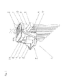
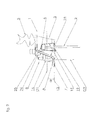
- the figures 1 and 2 show an embodiment of the plant holder 1 according to the invention being placed on a balustrade 2.
- the plant holder 1 comprises a ground box 3 configured to in use hold ground 4 in which a plant 5 is placed.
- the plant holder 1 comprises a balustrade receiving recess 6 configured to in use engage the balustrade 2 such that the plant holder 1 is supported by the balustrade 2.
- the plant holder 1 further comprises a tray 7 to in use hold a consumer good 8, such as food 9 and/or beverage 14.
- the tray 7 comprises a support surface 13 for supporting a consumer good 8 and is configured so that in use a consumer good 8 can be moved towards and on the support surface 13 in the direction A having an angle ⁇ being smaller than or around 20° relative to the support surface 13.
- the angle ⁇ may be smaller than or around 10°.
- the support surface 13 is configured to extend substantially horizontal when the plant holder 1 is supported by the balustrade 2.
- the recess 6 is formed by a first recess wall 15, a second recess wall 16 located at a distance from the first recess wall 15 and a top wall 23 interconnecting the first recess wall 15 and the second recess wall 16.
- the indicated direction D1 extends perpendicular to the second recess wall 16.
- the direction D2 extends perpendicular to the support surface 13.
- the line L2 extends through the support surface 13.
- the plant holder 1 comprises a positioning system 19 for positioning the plant holder 1 when supported by the balustrade 2 such that the support surface 13 of the tray 7 is located in a substantially horizontal position.
- the ground box 3, the recess 6 and the tray 7 are formed by a single molded holder body 10.
- the figures 3-7 show the plant holder 1 of the figures 1 and 2 .
- the tray 7 is connected to the second recess wall 16.
- the tray 7 extends over a distance T1 from the second recess wall 16 in the direction D1.
- the width of the tray 17 is indicated by T2.
- the tray 7 comprises a tray circumference 18.
- the tray 7 comprises a rim 17 extending along the tray circumferences 18. The rim 17 extends upwardly for the support surface 13 when the plant holder 1 is supported by the balustrade 2.
- a first part 29 of the tray circumference 18 is connected to the second recess wall 16.
- the rim 17 extends along a second part 30 of the tray circumference 18 which is not connected to the second recess wall 16.
- a part of the rim 17 extends over a distance R in the direction D2.
- the ratio R: T1 is smaller than or around 1:3.
- the ratio R: T1 may be smaller than or around 1:6.
- the distance R is smaller than or around 5 cm.
- the part of the rim 17 located at a distance of at least 0,5x T1 from the second recess wall 16 in the direction D1 extends over the distance R in the direction D2.
- the rim 17 comprises a top 20.
- the distance R in the direction D2 is measured from the top 20 to the support surface 13.
- the angle ⁇ of a line L1 extending between the top 20 and a part of the tray circumference 18 connected to the second recess wall 16 is smaller than or around 20°.
- the angle ⁇ may be smaller than or around 10°.
- the ground box 3 is located at a first side 11 of the recess and the tray 7 is located at an opposite second side 12 of the recess 6.
- the parts of the rim 17 located adjacent to the second recess wall 16 are connect to the second recess wall 16.
- the first recess wall has a height H1 and the second recess wall 16 has a height H2.
- the heights H1 and H2 are substantially equal.
- the parts of the rim 17 located adjacent to the second recess wall 16 are connected to the second recess wall 16 along the full height H2.
- the parts of the rim 17 located adjacent to the second recess wall 16 extend upwardly from the support surface 13 and along the full height H2 of the second recess wall 16.
- the positioning system 19 comprises positioning members 21, 22 configured to in use abut against the balustrade 2 and being adjustable to position the plant holder 3.
- the positioning members 21, 22 are located in the recess 6.
- the positioning system 19 comprises a first positioning member 21 and a second positioning member 22.
- the first positioning member 21 is located at the first recess wall 15 and the second positioning member 22 is located at the second recess wall 16.
- the first positioning member 21 comprises a first surface 26 configured to in use abut against the balustrade 2.
- the second positioning member 22 comprises a second surface 27 configured to in use abut against the balustrade 2.
- the distance P1 between the first surface 26 and the first recess wall 15 and the distance P2 between the second surface 27 and the second recess wall 16 are adjustable.
- the first positioning member 21 is adjustable in a direction traverse, preferable substantially perpendicular, to the first recess wall 15 and the second positioning member 22 is adjustable in a direction traverse, preferably substantially perpendicular, to the second recess wall 16.
- the first positioning member 21 extends substantially perpendicular from the first recess wall15, and the second positioning member 22 extends substantially perpendicular from the second recess wall 16.
- the first positioning member 21 and the second positioning member 22 have a U-like form.
- the second recess wall 16 has a width W.
- the second surface 27 of the second positioning member 22 extends along around 90% of the width W of the second recess wall 16.
- the second surface 27 of the second positioning member 22 may extend along around 80% or more of the width W of the second recess wall 16.
- the second surface 27 of the second positioning member 22 may extend along substantially the full width W of the second recess wall 16. This provides stability to the plant holder 1 when positioned on a balustrade.
- the top wall 23 is configured to be in contact with the balustrade 2 when the plant holder 1 is supported by the balustrade 2.
- the plant holder 1 comprises a box like member 24 configured to hold a consumer good 8 such as food 9 and/or beverage 14 and a connecting member 25.
- the box like member 24 is configured to be releasably connectable to the connecting member 25.
- the box like member 24 comprises a connector 32 to engage the connecting member 25.
- the box like member 24 comprises a box support surface 31 for supporting a consumer good 8.
- the connecting member 25 is located on the top wall 23.
- the connecting member 25 may be located on the second recess wall 16.
- the plant holder 1 may comprise a further tray configured to hold a consumer good, such as food 9 and/or beverage 14, and to be releasably connectable to the connecting member 25.
Landscapes
- Cultivation Receptacles Or Flower-Pots, Or Pots For Seedlings (AREA)
Abstract
A plant holder (1) configured to be placed on a balustrade, said plant holder comprises a ground box (3) configured to in use hold ground in which a plant is placed, a balustrade receiving recess (6) configured to in use engage the balustrade such that the plant holder is supported by the balustrade, and a tray (7) configured to in use hold a consumer good, such as food or beverage.
Description
- The invention relates to a plant holder configured to be placed on a balustrade. The plant holder comprises a ground box configured to in use hold ground in which a plant is placed and a balustrade receiving recess configured to in use engage the balustrade such that the plant holder is supported by the balustrade.
-
- The plant holder according the invention is configured to be placed on a balustrade and comprises a ground box configured to in use hold ground in which a plant is placed, a balustrade receiving recess configured to in use engage the balustrade such that the plant holder is supported by the balustrade, and a tray configured to in use hold a consumer good, such as food or beverage.
- The plant holder according the invention allows the user to place a consumer good, such as food or beverage, on the tray while standing or sitting near the plant holder supported by the balustrade. This means that when for example standing or sitting on a balcony, the user can on nice summer morning place a cup of coffee on the tray while enjoying the view of a beautiful plant held by the ground box.
- It is noted that the flower box disclosed in
EP1198984 comprises a tray portion. Said tray portion is an element which covers several components located between the underside of the flower box and the tray portion. It will be clear that a user will not be able to place a consumer good on the tray portion ofEP1198984 . -
EP1198984 also discloses a configuration of two interconnected flower boxes. It will be clear that the tray of the plant holder according the invention is completely different from the flower box ofEP1198984 . One places ground in the flower box ofEP1198984 . The user can place a consumer good on the tray of the plant holder according to the invention. Placing a item in the flower box ofEP1198984 requires a totally different movement of the user standing and even more when sitting on a balcony than placing an item on the tray of the plant holder according the invention. Furthermore, the user will not place a consumer good, such as food and beverage in the flower box ofEP1198984 , because a flower box is not considered as being hygienic. - In an embodiment of the plant holder according to the invention, the tray comprises a support surface for supporting the consumer good and is configured such that in use the consumer good can be moved towards the support surface in a direction having an angle α being smaller than or around 20° relative to the support surface. This allows the user standing or sitting near the balustrade to conveniently place a consumer good, such as a cup of coffee, on the tray. The angle α may be smaller than or around 10°.
- In an embodiment of the plant holder according to the invention, the support surface of the tray is configured to extend substantially horizontal when the plant holder is supported by the balustrade.
- In an embodiment of the plant holder according to the invention, the ground box, the recess and the tray are formed by a single molded holder body.
- The plant holder according the invention will be discussed in detail with reference to the accompanying drawings, wherein
-
Figure 1 , schematically shows a perspective view of an embodiment of the plant holder according to the invention. -
Figure 2 , schematically shows a side view of the plant holder offigure 1 , -
Figure 3 , schematically shows a perspective view of the plant holder offigure 1 , -
Figure 4 , schematically shows a side view of the plant holder offigure 1 , -
Figure 5 , schematically shows a top view of the plant holder offigure 1 , -
Figure 6 , schematically shows a front view of the plant holder offigure 1 , -
Figure 7 , schematically shows a perspective view of the plant holder offigure 1 , -
Figure 8 , schematically shows a bottom view of the plant holder offigure 1 , -
Figure 9 , schematically shows an exploded view of the plant holder offigure 1 . - The
figures 1 and2 show an embodiment of theplant holder 1 according to the invention being placed on abalustrade 2. Theplant holder 1 comprises aground box 3 configured to in use holdground 4 in which a plant 5 is placed. Theplant holder 1 comprises abalustrade receiving recess 6 configured to in use engage thebalustrade 2 such that theplant holder 1 is supported by thebalustrade 2. Theplant holder 1 further comprises atray 7 to in use hold a consumer good 8, such as food 9 and/orbeverage 14. - The
tray 7 comprises asupport surface 13 for supporting a consumer good 8 and is configured so that in use a consumer good 8 can be moved towards and on thesupport surface 13 in the direction A having an angle α being smaller than or around 20° relative to thesupport surface 13. The angle α may be smaller than or around 10°. - The
support surface 13 is configured to extend substantially horizontal when theplant holder 1 is supported by thebalustrade 2. Therecess 6 is formed by afirst recess wall 15, asecond recess wall 16 located at a distance from thefirst recess wall 15 and atop wall 23 interconnecting thefirst recess wall 15 and thesecond recess wall 16. - The indicated direction D1 extends perpendicular to the
second recess wall 16. The direction D2 extends perpendicular to thesupport surface 13. The line L2 extends through thesupport surface 13. - The
plant holder 1 comprises apositioning system 19 for positioning theplant holder 1 when supported by thebalustrade 2 such that thesupport surface 13 of thetray 7 is located in a substantially horizontal position. - The
ground box 3, therecess 6 and thetray 7 are formed by a single moldedholder body 10. - The
figures 3-7 show theplant holder 1 of thefigures 1 and2 . Thetray 7 is connected to thesecond recess wall 16. Thetray 7 extends over a distance T1 from thesecond recess wall 16 in the direction D1. The width of thetray 17 is indicated by T2. Thetray 7 comprises atray circumference 18. Thetray 7 comprises arim 17 extending along thetray circumferences 18. Therim 17 extends upwardly for thesupport surface 13 when theplant holder 1 is supported by thebalustrade 2. - A
first part 29 of thetray circumference 18 is connected to thesecond recess wall 16. Therim 17 extends along asecond part 30 of thetray circumference 18 which is not connected to thesecond recess wall 16. A part of therim 17 extends over a distance R in the direction D2. The ratio R: T1 is smaller than or around 1:3. The ratio R: T1 may be smaller than or around 1:6. The distance R is smaller than or around 5 cm. The part of therim 17 located at a distance of at least 0,5x T1 from thesecond recess wall 16 in the direction D1 extends over the distance R in the direction D2. - The
rim 17 comprises atop 20. The distance R in the direction D2 is measured from thetop 20 to thesupport surface 13. For at least part of therim 17, the angle β of a line L1 extending between thetop 20 and a part of thetray circumference 18 connected to thesecond recess wall 16 is smaller than or around 20°. The angle β may be smaller than or around 10°. - The
ground box 3 is located at afirst side 11 of the recess and thetray 7 is located at an oppositesecond side 12 of therecess 6. - The parts of the
rim 17 located adjacent to thesecond recess wall 16 are connect to thesecond recess wall 16. The first recess wall has a height H1 and thesecond recess wall 16 has a height H2. The heights H1 and H2 are substantially equal. The parts of therim 17 located adjacent to thesecond recess wall 16 are connected to thesecond recess wall 16 along the full height H2. The parts of therim 17 located adjacent to thesecond recess wall 16 extend upwardly from thesupport surface 13 and along the full height H2 of thesecond recess wall 16. - The
positioning system 19 comprises positioningmembers balustrade 2 and being adjustable to position theplant holder 3. Thepositioning members recess 6. Thepositioning system 19 comprises afirst positioning member 21 and asecond positioning member 22. Thefirst positioning member 21 is located at thefirst recess wall 15 and thesecond positioning member 22 is located at thesecond recess wall 16. - The
first positioning member 21 comprises afirst surface 26 configured to in use abut against thebalustrade 2. Thesecond positioning member 22 comprises asecond surface 27 configured to in use abut against thebalustrade 2. The distance P1 between thefirst surface 26 and thefirst recess wall 15 and the distance P2 between thesecond surface 27 and thesecond recess wall 16 are adjustable. Thefirst positioning member 21 is adjustable in a direction traverse, preferable substantially perpendicular, to thefirst recess wall 15 and thesecond positioning member 22 is adjustable in a direction traverse, preferably substantially perpendicular, to thesecond recess wall 16. - The
first positioning member 21 extends substantially perpendicular from the first recess wall15, and thesecond positioning member 22 extends substantially perpendicular from thesecond recess wall 16. - The
first positioning member 21 and thesecond positioning member 22 have a U-like form. - The
second recess wall 16 has a width W. Thesecond surface 27 of thesecond positioning member 22 extends along around 90% of the width W of thesecond recess wall 16. Thesecond surface 27 of thesecond positioning member 22 may extend along around 80% or more of the width W of thesecond recess wall 16. Thesecond surface 27 of thesecond positioning member 22 may extend along substantially the full width W of thesecond recess wall 16. This provides stability to theplant holder 1 when positioned on a balustrade. - The
top wall 23 is configured to be in contact with thebalustrade 2 when theplant holder 1 is supported by thebalustrade 2. - The
plant holder 1 comprises a box likemember 24 configured to hold a consumer good 8 such as food 9 and/orbeverage 14 and a connectingmember 25. The box likemember 24 is configured to be releasably connectable to the connectingmember 25. The box likemember 24 comprises aconnector 32 to engage the connectingmember 25. The box likemember 24 comprises abox support surface 31 for supporting a consumer good 8. - The connecting
member 25 is located on thetop wall 23. The connectingmember 25 may be located on thesecond recess wall 16. - In addition to or in stead of the box like
member 24, theplant holder 1 may comprise a further tray configured to hold a consumer good, such as food 9 and/orbeverage 14, and to be releasably connectable to the connectingmember 25. - The invention may be defined by any of the following clauses.
- 1. Plant holder (1) configured to be placed on a balustrade, said plant holder comprises
- a ground box (3) configured to in use hold ground in which a plant is placed,
- a balustrade receiving recess (6) configured to in use engage the balustrade such that the plant holder is supported by the balustrade, and
- a tray (7) configured to in use hold a consumer good, such as food or beverage.
- 2. Plant holder according to
clause 1, wherein the tray- comprises a support surface (13) for supporting the consumer good and
- is configured such that in use the consumer good can be moved towards the support surface in a direction having an angle α being smaller than or around 20° relative to the support surface.
- 3. Plant holder according to
clause 2, wherein the tray comprises a support surface which is configured to extend substantially horizontal when the plant holder is supported by the balustrade. - 4. Plant holder according to any of the preceding clauses, wherein
- the recess is formed by a first recess wall (15) and a second recess wall (16) located at a distance from the first recess wall.
- 5. Plant holder according to
clause 4, wherein- the tray is connected to the second recess wall
- the tray extends over a distance T1 from the second recess wall in a direction D1 perpendicular to the second recess wall.
- 6. Plant holder according to any of the preceding clauses, wherein the tray comprises a tray circumference (18).
- 7. Plant holder according to
clause 6, wherein the tray comprises a rim (17) extending along the tray circumference, which rim extends upwardly from the support surface when the plant holder is supported by the balustrade. - 8. Plant holder according to
clause 7, wherein a part of the tray circumference is connected to the second recess wall, and the rim extends along an other part of the tray circumference which is not connected to second recess wall. - 9. Plant holder according to any of the clauses 7-8, wherein at least part of the rim extends over a distance R in a direction D2 perpendicular to the support surface, and the ratio R : T1 is smaller than or around 1:3.
- 10. Plant holder according to any of the clauses 7-9, wherein at least part of the rim extends over a distance R in a direction D2 perpendicular to the support surface, and the distance R is smaller than or around 5 cm.
- 11. Plant holder according to any of the clauses 7-10, wherein the part of the rim located at a distance of at least 0,5 x T1 from the second recess wall in the direction D1 extends over a distance R in a direction D2 perpendicular to the support surface.
- 12. Plant holder according to any of the clauses 7-11, wherein the rim comprises a top (20) and for at least part of the rim the angle β of a line extending between the top and the part of the tray circumference connected to the second recess wall is smaller than or around 20°.
- 13. Plant holder according to any of the preceding clauses, wherein the ground box is located at one side of the recess and the tray is located at the opposite side of the recess.
- 14. Plant holder according to any of the preceding clauses, wherein the ground box, the recess and the tray are formed by a single molded holder body (10).
- 15. Plant holder according to any of the clauses 7-14, wherein the parts of the rim located adjacent to the second recess wall are connected to the second recess wall.
- 16. Plant holder according to any of the clauses 7-15, wherein the second recess wall has a height H2, and the parts of the rim located adjacent to the second recess wall are connected to the second recess wall along substantially the full height H2.
- 17. Plant holder according to any of the preceding clauses, wherein the plant holder comprises a positioning system for positioning the plant holder when supported by the balustrade (such that the support surface of the tray is located in a substantially horizontal position).
- 18. Plant holder according to
clause 17, wherein the positioning system comprises positioning members configured to in use abut against the balustrade and being adjustable to position the plant holder. - 19. Plant holder according to any of the clauses 17-18, wherein the positioning members are located in the recess.
- 20. Plant holder according to any of the clauses 17-19, wherein the positioning system comprises a first positioning member and a second positioning member.
- 21. Plant holder according to
clause 20, wherein the first positioning member is located at the first recess wall and the second positioning member at located in the second recess wall. - 22. Plant holder according to any of the clauses 20-21, wherein the first positioning member extends substantially perpendicular from the first recess wall, and the second positioning member extends substantially perpendicular from the second recess wall.
- 23. Plant holder according to any of the clauses 20-22, wherein the first positioning member comprises a first surface configured to in use abut against the balustrade and the second positioning member comprises a second surface configured to in use abut against the balustrade.
- 24. Plant holder according to
clause 23, wherein the distance P1 between the first surface and the first recess wall and the distance P2 between the second surface and the second recess wall are adjustable. - 25. Plant holder according to
clause 24, wherein the first positioning member is adjustable in a direction traverse, preferable substantially perpendicular, to the first recess wall and the second positioning member is adjustable in a direction traverse, preferably substantially perpendicular, to thesecond recess wall 16. - 26. Plant holder according to any of the clauses 20-25, wherein the first positioning member and the second positioning member have a U-like form.
- 27. Plant holder according to any of the clauses 20-26, wherein the second recess wall has a width W and the second surface of the second positioning member extends around 80% or more of the width W of the second recess wall.
- 28. Plant holder according to any of the clauses 4-27, wherein the recess comprises a top wall interconnecting the first recess wall and the second recess wall.
- 29. Plant holder according to clause 28, wherein the top wall is configured to be in contact with the balustrade when the plant holder is supported by the balustrade.
- 30. Plant holder according to any of the preceding clauses, wherein the plant holder comprises a further tray configured to hold a consumer good, such as food or beverage, and a connecting member, wherein the further tray is configured to be releasably connectable to the connecting member.
- 31. Plant holder according to any of the preceding clauses, wherein the plant holder comprises a box-like member configured to hold a consumer good, such as drinking cup, and a connecting member, wherein the box-like member is configured to be releasably connectable to the connecting member.
- 32. Plant holder according to the
clauses - 33. Plant holder according to the
clauses - 34. Use of a plant holder according to any of preceding clauses.
- It will be clear that many modifications of the shown embodiment of the plant holder according to the invention are possible without departing from the scope of protection as defined in the claims.
Claims (15)
- Plant holder (1) configured to be placed on a balustrade, said plant holder comprises- a ground box (3) configured to in use hold ground in which a plant is placed,- a balustrade receiving recess (6) configured to in use engage the balustrade such that the plant holder is supported by the balustrade, and- a tray (7) configured to in use hold a consumer good, such as food or beverage.
- Plant holder according to claim 1, wherein the tray- comprises a support surface (13) for supporting the consumer good and- is configured such that in use the consumer good can be moved towards the support surface in a direction having an angle α being smaller than or around 20° relative to the support surface.
- Plant holder according to claim 2, wherein the tray comprises a support surface which is configured to extend substantially horizontal when the plant holder is supported by the balustrade.
- Plant holder according to any of the preceding claims, wherein- the recess is formed by a first recess wall (15) and a second recess wall (16) located at a distance from the first recess wall.
- Plant holder according to claim 4, wherein- the tray is connected to the second recess wall- the tray extends over a distance T1 from the second recess wall in a direction D1 perpendicular to the second recess wall.
- Plant holder according to any of the preceding claims, wherein the tray comprises a tray circumference (18).
- Plant holder according to claim 6, wherein the tray comprises a rim (17) extending along the tray circumference, which rim extends upwardly from the support surface when the plant holder is supported by the balustrade.
- Plant holder according to claim 7, wherein a part of the tray circumference is connected to the second recess wall, and the rim extends along an other part of the tray circumference which is not connected to second recess wall.
- Plant holder according to any of the claims 7-8, wherein at least part of the rim extends over a distance R in a direction D2 perpendicular to the support surface, and the ratio R : T1 is smaller than or around 1:3.
- Plant holder according to any of the claims 7-9, wherein at least part of the rim extends over a distance R in a direction D2 perpendicular to the support surface, and the distance R is smaller than or around 5 cm.
- Plant holder according to any of the claims 7-10, wherein the part of the rim located at a distance of at least 0,5 x T1 from the second recess wall in the direction D1 extends over a distance R in a direction D2 perpendicular to the support surface.
- Plant holder according to any of the claims 7-11, wherein the rim comprises a top (20) and for at least part of the rim the angle β of a line extending between the top and the part of the tray circumference connected to the second recess wall is smaller than or around 20°.
- Plant holder according to any of the preceding claims, wherein the ground box is located at one side of the recess and the tray is located at the opposite side of the recess.
- Plant holder according to any of the preceding claims, wherein the ground box, the recess and the tray are formed by a single molded holder body (10).
- Plant holder according to any of the claims 7-14, wherein the parts of the rim located adjacent to the second recess wall are connected to the second recess wall.
Priority Applications (1)
| Application Number | Priority Date | Filing Date | Title |
|---|---|---|---|
| EP11150984A EP2476350A1 (en) | 2011-01-14 | 2011-01-14 | Plant holder |
Applications Claiming Priority (1)
| Application Number | Priority Date | Filing Date | Title |
|---|---|---|---|
| EP11150984A EP2476350A1 (en) | 2011-01-14 | 2011-01-14 | Plant holder |
Publications (1)
| Publication Number | Publication Date |
|---|---|
| EP2476350A1 true EP2476350A1 (en) | 2012-07-18 |
Family
ID=44712932
Family Applications (1)
| Application Number | Title | Priority Date | Filing Date |
|---|---|---|---|
| EP11150984A Withdrawn EP2476350A1 (en) | 2011-01-14 | 2011-01-14 | Plant holder |
Country Status (1)
| Country | Link |
|---|---|
| EP (1) | EP2476350A1 (en) |
Cited By (1)
| Publication number | Priority date | Publication date | Assignee | Title |
|---|---|---|---|---|
| US20240130555A1 (en) * | 2023-12-31 | 2024-04-25 | Ryan M Hamze | Weight-Balanced Window Ledge Planter |
Citations (6)
| Publication number | Priority date | Publication date | Assignee | Title |
|---|---|---|---|---|
| US5722329A (en) * | 1997-01-13 | 1998-03-03 | Weng; Jung-Yi | Wall flower support structure |
| FR2774576A1 (en) * | 1998-02-06 | 1999-08-13 | Bouillard Freres | Plant holder for balcony with tank for plants |
| EP1198984A2 (en) | 2000-10-16 | 2002-04-24 | Plastecnic S.p.A. | Multifunctional flower box |
| US20050193625A1 (en) * | 2004-02-18 | 2005-09-08 | Rosser Trudy B. | Support system |
| AU2008203794A1 (en) * | 2007-08-09 | 2009-02-26 | Troy Reginald Griffin | Balcony tray |
| WO2010117915A1 (en) * | 2009-04-06 | 2010-10-14 | Sharon Duncan | Plant pot tray |
-
2011
- 2011-01-14 EP EP11150984A patent/EP2476350A1/en not_active Withdrawn
Patent Citations (6)
| Publication number | Priority date | Publication date | Assignee | Title |
|---|---|---|---|---|
| US5722329A (en) * | 1997-01-13 | 1998-03-03 | Weng; Jung-Yi | Wall flower support structure |
| FR2774576A1 (en) * | 1998-02-06 | 1999-08-13 | Bouillard Freres | Plant holder for balcony with tank for plants |
| EP1198984A2 (en) | 2000-10-16 | 2002-04-24 | Plastecnic S.p.A. | Multifunctional flower box |
| US20050193625A1 (en) * | 2004-02-18 | 2005-09-08 | Rosser Trudy B. | Support system |
| AU2008203794A1 (en) * | 2007-08-09 | 2009-02-26 | Troy Reginald Griffin | Balcony tray |
| WO2010117915A1 (en) * | 2009-04-06 | 2010-10-14 | Sharon Duncan | Plant pot tray |
Non-Patent Citations (1)
| Title |
|---|
| ASHLEY BUTLER: "balconcept balcony table + flowerbox", 16 February 2011 (2011-02-16), XP002660918, Retrieved from the Internet <URL:http://www.basicgardendesign.com/home-improvement-advisor/balconcept-balcony-table-flowerbox> [retrieved on 20111010] * |
Cited By (1)
| Publication number | Priority date | Publication date | Assignee | Title |
|---|---|---|---|---|
| US20240130555A1 (en) * | 2023-12-31 | 2024-04-25 | Ryan M Hamze | Weight-Balanced Window Ledge Planter |
Similar Documents
| Publication | Publication Date | Title |
|---|---|---|
| USD692760S1 (en) | Reinforced-ring container for beverage-making products | |
| USD620711S1 (en) | Single tray container | |
| USD674463S1 (en) | Filter for a liquid dispenser | |
| USD579714S1 (en) | Covered cookware vessel | |
| USD695615S1 (en) | Reinforced-ring container for beverage-making products | |
| USD734154S1 (en) | Beverage container | |
| USD692759S1 (en) | Flat-rimmed container for beverage-making products | |
| USD596074S1 (en) | Flower pot with saucer | |
| USD678772S1 (en) | Beverage container | |
| USD687710S1 (en) | Beverage container | |
| USD587519S1 (en) | Covered saute pan | |
| USD621723S1 (en) | Beverage container | |
| USD661544S1 (en) | Ingredient reservoir insert for a beverage shaker cup | |
| USD655532S1 (en) | Articulated support arm attachment for a table leg | |
| USD697404S1 (en) | Beverage container | |
| USD593365S1 (en) | Beverage container | |
| USD662361S1 (en) | Beverage container | |
| USD620757S1 (en) | Drinking cup | |
| USD623900S1 (en) | Drinking cup | |
| USD622087S1 (en) | Weight activated restraining pillow | |
| USD619362S1 (en) | Single tray undermount container | |
| USD617139S1 (en) | Cookware side handle | |
| USD649442S1 (en) | Raised stand for a playing surface of a pool table | |
| USD662730S1 (en) | Coffee table | |
| USD644459S1 (en) | Support base |
Legal Events
| Date | Code | Title | Description |
|---|---|---|---|
| PUAI | Public reference made under article 153(3) epc to a published international application that has entered the european phase |
Free format text: ORIGINAL CODE: 0009012 |
|
| AK | Designated contracting states |
Kind code of ref document: A1 Designated state(s): AL AT BE BG CH CY CZ DE DK EE ES FI FR GB GR HR HU IE IS IT LI LT LU LV MC MK MT NL NO PL PT RO RS SE SI SK SM TR |
|
| AX | Request for extension of the european patent |
Extension state: BA ME |
|
| STAA | Information on the status of an ep patent application or granted ep patent |
Free format text: STATUS: THE APPLICATION IS DEEMED TO BE WITHDRAWN |
|
| 18D | Application deemed to be withdrawn |
Effective date: 20130119 |