EP2476059B1 - A method and apparatus for determining processor performance - Google Patents
A method and apparatus for determining processor performance Download PDFInfo
- Publication number
- EP2476059B1 EP2476059B1 EP10760390.4A EP10760390A EP2476059B1 EP 2476059 B1 EP2476059 B1 EP 2476059B1 EP 10760390 A EP10760390 A EP 10760390A EP 2476059 B1 EP2476059 B1 EP 2476059B1
- Authority
- EP
- European Patent Office
- Prior art keywords
- processor
- identifier
- data
- tile
- unit
- Prior art date
- Legal status (The legal status is an assumption and is not a legal conclusion. Google has not performed a legal analysis and makes no representation as to the accuracy of the status listed.)
- Active
Links
Images


Classifications
-
- G—PHYSICS
- G06—COMPUTING OR CALCULATING; COUNTING
- G06F—ELECTRIC DIGITAL DATA PROCESSING
- G06F11/00—Error detection; Error correction; Monitoring
- G06F11/30—Monitoring
- G06F11/34—Recording or statistical evaluation of computer activity, e.g. of down time, of input/output operation ; Recording or statistical evaluation of user activity, e.g. usability assessment
- G06F11/3409—Recording or statistical evaluation of computer activity, e.g. of down time, of input/output operation ; Recording or statistical evaluation of user activity, e.g. usability assessment for performance assessment
- G06F11/3419—Recording or statistical evaluation of computer activity, e.g. of down time, of input/output operation ; Recording or statistical evaluation of user activity, e.g. usability assessment for performance assessment by assessing time
-
- G—PHYSICS
- G06—COMPUTING OR CALCULATING; COUNTING
- G06F—ELECTRIC DIGITAL DATA PROCESSING
- G06F11/00—Error detection; Error correction; Monitoring
- G06F11/30—Monitoring
- G06F11/34—Recording or statistical evaluation of computer activity, e.g. of down time, of input/output operation ; Recording or statistical evaluation of user activity, e.g. usability assessment
- G06F11/3409—Recording or statistical evaluation of computer activity, e.g. of down time, of input/output operation ; Recording or statistical evaluation of user activity, e.g. usability assessment for performance assessment
-
- G—PHYSICS
- G06—COMPUTING OR CALCULATING; COUNTING
- G06F—ELECTRIC DIGITAL DATA PROCESSING
- G06F11/00—Error detection; Error correction; Monitoring
- G06F11/30—Monitoring
- G06F11/34—Recording or statistical evaluation of computer activity, e.g. of down time, of input/output operation ; Recording or statistical evaluation of user activity, e.g. usability assessment
- G06F11/3409—Recording or statistical evaluation of computer activity, e.g. of down time, of input/output operation ; Recording or statistical evaluation of user activity, e.g. usability assessment for performance assessment
- G06F11/3419—Recording or statistical evaluation of computer activity, e.g. of down time, of input/output operation ; Recording or statistical evaluation of user activity, e.g. usability assessment for performance assessment by assessing time
- G06F11/3423—Recording or statistical evaluation of computer activity, e.g. of down time, of input/output operation ; Recording or statistical evaluation of user activity, e.g. usability assessment for performance assessment by assessing time where the assessed time is active or idle time
-
- G—PHYSICS
- G06—COMPUTING OR CALCULATING; COUNTING
- G06F—ELECTRIC DIGITAL DATA PROCESSING
- G06F11/00—Error detection; Error correction; Monitoring
- G06F11/30—Monitoring
- G06F11/34—Recording or statistical evaluation of computer activity, e.g. of down time, of input/output operation ; Recording or statistical evaluation of user activity, e.g. usability assessment
- G06F11/3466—Performance evaluation by tracing or monitoring
-
- G—PHYSICS
- G06—COMPUTING OR CALCULATING; COUNTING
- G06F—ELECTRIC DIGITAL DATA PROCESSING
- G06F11/00—Error detection; Error correction; Monitoring
- G06F11/30—Monitoring
- G06F11/34—Recording or statistical evaluation of computer activity, e.g. of down time, of input/output operation ; Recording or statistical evaluation of user activity, e.g. usability assessment
- G06F11/3466—Performance evaluation by tracing or monitoring
- G06F11/3476—Data logging
-
- G—PHYSICS
- G06—COMPUTING OR CALCULATING; COUNTING
- G06T—IMAGE DATA PROCESSING OR GENERATION, IN GENERAL
- G06T15/00—Three-dimensional [3D] image rendering
- G06T15/005—General purpose rendering architectures
-
- G—PHYSICS
- G06—COMPUTING OR CALCULATING; COUNTING
- G06F—ELECTRIC DIGITAL DATA PROCESSING
- G06F2201/00—Indexing scheme relating to error detection, to error correction, and to monitoring
- G06F2201/88—Monitoring involving counting
Definitions
- the present invention relates to a method and apparatus for determining processor performance.
- the Perfmon Block receives the data from the graphics and/or audio processor at the same operating frequency as the processor.
- the performance data for each processor is generated by the Perfmon Block from this received data.
- This generated performance data and the call to which the generated performance data refers is then output to the memory to be analysed by the CPU.
- the performance data is output at a fixed sample rate.
- US2008/033696 discloses incrementing a counter when a utilisation condition is met.
- US2004/088699 discloses inserting probe points into an executing program and measuring the time taken to get from one probe point to the next probe point.
- 'Internal processes state performance monitoring', research disclosure, Mason Publications, Hampshire, GB; No. 335, page 221; ISSN 0374-4353 discloses the use of microcode within a processor to provide a self-monitoring function.
- an apparatus according to claim 7, a computer device according to claim 13, a computer program according to claim 14 and a computer readable storage medium according to claim 15.
- the developer system 100 includes the components of the computer on which the software will run.
- the developer system includes the components of a handheld console and specifically an audio processor 115, a graphics processor 120, a display driver 130 and a central processing unit 125.
- the developer system 100 includes a performance monitor block 110 (a perfmon block) and a memory 105 coupled to the perfmon block 110.
- the handheld console also includes the perfmon block. However, it is envisaged that the perfmon block in the handheld console will not be operative.
- the CPU 125 is connected to the display driver 130, the graphics processor 120, the perfmon block 110, the audio processor 115 and the memory 105.
- the graphics processor 120 is additionally connected to the display driver 130 and the perfmon block 110.
- the perfmon block 110 is additionally connected to the memory 105, the audio processor 115 and the display driver 130.
- the graphics processor unit 120 uses tile-based deferred rendering (referred to as "TBDR" hereinafter) to generate computer graphics.
- TBDR is a known method for rendering computer graphics and is particularly suited to hand-held consoles. TBDR is described in general with reference to Figure 2 .
- Figure 2 shows an image 200 of a first rectangle 201 and a second rectangle 210.
- the CPU 125 instructs the graphics processor 120 to draw both the first rectangle 201 and the second rectangle 210.
- This instruction is performed using "batches".
- the first rectangle 201 is a first batch of work to be drawn by the graphics processor 120.
- This first batch of work is given a unique identifier in the image 200 by the graphics processor 110.
- the second rectangle 210 is a second batch of work to be drawn by the graphics processor 120.
- This second batch of work is given a unique identifier in the image 200 by the graphics processor 110.
- the batch identifier is generated by the graphics processor 120 when instructed to draw the first and second rectangle by the CPU 125.
- the graphics processor 120 increments the identifier upon receiving each new batch.
- the unique identifier is seeded to be "0" at the start of every frame.
- the size of the identifier has to be large enough to ensure that the unique identifier is unique within the frame.
- the CPU 125 as part of the batch process provides the graphics processor 120 with polygon information required to draw both rectangles 201, 210.
- This polygon information details the polygons which will be used to make up the first rectangle 201 and the second rectangle 210.
- these polygons are triangles although the invention is not so limited and any polygon can be used as appreciated.
- Associated with each polygon are colour, shading and texture information.
- a tile 205 is a block of pixels in some embodiments, although the invention is not so limited.
- each tile is a block of pixels which is 4 pixels wide (i.e. 4 pixels in the x-direction) and 4 pixels high (i.e. 4 pixels in the y-direction), although other appropriate sizes such as 16 pixels wide and 16 pixels high are also envisaged.
- the tiles may be single pixels or may even be non-uniform.
- a tile may be 16 pixels wide and only 4 pixels high. It should be noted here that the allocation of the tile is made when the image is to be rendered. In other words, in one image on the screen each tile may be 4 pixels wide and 4 pixels high but in the next image on the screen, each tile may be 16 pixels wide and 16 pixels high.
- Each tile is given a unique identifier. This enables the graphics processor 120 to identify each tile uniquely in the image.
- the tiles are given an identifier based on the location, in terms of x,y co-ordinates of one point of the tile on the screen. So, in the example of Figure 2 , the co-ordinates of point 206' is the point of tile 206 that determines the identifier of the tile. As the tile is 4 pixels wide and 4 pixels high, point 206' is located at position (4,4) on the screen - where the top left corner of the image is (0,0). Thus, tile 206 is given the identifier tile(4,4). Similarly, point 207' is located at (8,4) and so the identifier of tile 207 is tile(8,4). This identification process is carried out for each tile in the image 200. It should be noted that the invention is not limited to this numbering system, and any system enabling any tile to be uniquely identified in the image is envisaged.
- the geometry phase There are two distinct phases in embodiments of the present invention.
- the division of the screen into tiles takes place during the geometry phase, and the drawing of the two rectangles takes place during the rasterisation phase.
- the graphics processor 120 will draw the first and second rectangle 201 and 210 using the polygons provided by the CPU 125. This is illustrated in Figure 2 .
- the polygons are triangles and only a first triangle 202 and a second triangle 225 are highlighted.
- the triangles are defined by their three vertices. So, for example, triangle 202 will be defined by the pixel positions ABC.
- the vertices of the triangle provide a unique identifier for each triangle.
- triangle 225 it should be noted that two areas of the triangle 220 and 220' are located underneath other triangles. This is indicated in the Figures by dashed lines. In other words, areas 220 and 220' will not be visible in the image 200.
- the graphics processor 120 determines which tiles contain which triangle. This can be achieved because the vertices of each triangle are known and the geometry of each tile is also known. This means that the graphics processor 120 knows for each batch which tiles are to be used and determines for each tile the triangles that are to be placed in that tile, as well as the colour and texture information for each triangle.
- the above is the geometry phase of rendering in TBDR..
- the graphics processor 120 sorts the triangles so that only areas that are to appear on the screen will ultimately be rendered. In other words, as the areas 220 and 220' of the triangle 225 are located underneath other triangles (and so would not be visible on the screen), areas 220 and 220' will not be rendered on the screen. This is part of the rasterisation phase of rendering in TBDR, although it could be carried out as part of the geometry phase.
- Figure 3 shows a block diagram of the graphics processor 120.
- the graphics processor 120 in embodiments of the invention, has a geometry phase block 305 connected to an intermediate buffer 310 by a bus.
- the intermediate buffer 310 is connected to a rasterisation phase block 315 again by a bus.
- the acquired information is fed into the intermediate buffer 310 for storage.
- the data is stored in a manner shown in Figure 4 . As is seen in Figure 4 , for each tile ID the polygons making up that tile are defined. Additionally, for each identified polygon, the batch ID, colour, texture and shading data are stored.
- the rasterisation phase block 315 In order to generate the image 200 on the screen, relevant information stored in the intermediate buffer 310 is retrieved by the rasterisation phase block 315.
- the rasterisation phase block 315 does not draw each batch. Instead the rasterisation block 315 draws each tile.
- the rasterisation phase block 315 In order to draw a tile, the rasterisation phase block 315 firstly determines the tile upon which it is about to work. The rasterisation phase block 315 uses the obtained polygon information to draw the visible areas of the polygon. The appropriate colour, shading and texture are applied to the visible areas of that polygon.
- Time slicing is the process by which the graphics processor 120 draws a tile out of sequence. This can occur if the graphics processor 120 starts drawing a tile but requires other information to complete the drawing of the tile currently being drawn. Typically, this may be some texture data from the CPU 125. Rather than waiting for that other information to complete the drawing of that tile, the graphics processor 120 starts drawing another tile.
- a tile After a tile is drawn, it is moved from the rasterisation phase block 315 of the graphics processor 120 to the display driver 130 for storage in an image buffer (not shown). After all the tiles have been completed, and stored in the image buffer of the display driver 130, the image 200 is output to a screen.
- performance data may be data indicating that the processor is running at a certain capacity, or indicating that the processor has crashed.
- the Perfmon block 110 obtains data from each processor in the system 100.
- the perfmon block 110 determines the performance of the graphics processor 120 when generating image 200.
- the perfmon block 110 receives a number of count signals from the graphics processor 120.
- the graphics processor 120 has a number of count signals issued therefrom and the perfmon block 110 has a corresponding number of counters included therein (i.e. one counter in the perfmon block 110 for each count signal from the graphics processor).
- the perfmon block 110 has a corresponding number of counters included therein (i.e. one counter in the perfmon block 110 for each count signal from the graphics processor).
- the perfmon block 110 receives a number of count signals from the graphics processor 120.
- the graphics processor 120 has a number of count signals issued therefrom and the perfmon block 110 has a corresponding number of counters included therein (i.e. one counter in the perfmon block 110 for each count signal from the graphics processor).
- the count signal from the graphics processor is either a 1 or a 0 and cycles between the two values at the same frequency as the clock frequency of the graphics processor unit 120. This count signal is fed into one 16 bit counter located within the perfmon block 110. The counter within the perfmon block 110 count each time the count signal from the graphics processor 120 goes to 1. Additionally fed into the perfmon block 110 from the graphics processor 120 is information identifying the task that the graphics processor 120 is currently performing.
- This task is the batch ID and the tile ID currently being performed by the graphics processor 120.
- the batch ID and tile ID are output to the perfmon block 110 alongside the counter signal. As the batch ID and tile ID are output at the same frequency as the counter signal, the perfmon block 110 is able to determine how long each task performed by the graphics processor 120 takes.
- the perfmon block 110 begins at step 501.
- the CPU 125 issues two batch instructions to the graphics processor at step 502. As noted above, one batch instruction relates to the first rectangle 201 and the second batch instruction relates to the second rectangle 210. Each batch instruction includes the polygon information required to draw the first and second rectangle respectively.
- the graphics processor 120 begins the geometry phase of the image processing at step 503. In order to perform the geometry phase of the image processing, the graphics processor 120 begins processing the first batch instruction at step 504. In other words, the graphics processor 120 begins the geometry phase processing of the first rectangle 201. This will be apparent to the perfmon block 110 because the batch ID output thereto will indicate the batch ID of the first rectangle 201. As the counter in the perfmon block 110 counts the number of times the count signal in the graphics processor 120 goes to 1 (i.e. the number of clock cycles used by the graphics processor 120 in processing the first batch in the geometry phase), the perfmon block 110 output can thus be used to determine the length of time required by the graphics processor 120 to process the first batch in the geometry phase.
- the tiles in which the first rectangle 201 will be drawn, and associated polygons, are determined (step 505). This concludes the geometry phase for the first batch (i.e. the first rectangle 201). It is decided whether this batch is the last batch that needs geometry phase processing (step 507). In this case, there is a second batch to process (i.e. the second rectangle 210).
- step 506 the batch ID that is processed is changed.
- This change in batch ID for example, means that a valid "condition" is met.
- the value of the counter within the perfmon block 110 for this batch ID, along with the batch ID itself, is output to the memory 105.
- the counter within the perfmon block 110 is then reset.
- the batch ID is given as an example condition, the invention is not so limited and any arbitrary condition is also envisaged.
- the second batch (i.e. second rectangle) is then subjected to the geometry phase processing as explained above.
- step 508 the graphics processor 210 then commences the rasterisation phase.
- the first tile is rasterised (step 509).
- the counter signal and the tile ID is output to the perfmon block 110. This again indicates the length of time taken to rasterise the first tile.
- a check is carried out at step 510 to determine if this rasterised tile is the final tile to be processed. As the tile is not the final tile to be rasterised then the tile ID is incremented and the next tile is rasterised (step 511).
- the incrementing of the tile ID to generate the new tile ID is a valid "condition" and so the value of the counter in the perfmon block 110, along with the tile ID is output to the memory 105 and stored in association therein.
- the counter is then reset.
- step 510 If at step 510 the check indicates that the tile that had just been rasterised is the final tile, then the process ends (step 512).
- a timestamp is also provided to the perfmon block 110.
- the timestamp is obtained from a system-wide clock which defines the time at which the counter value and the batch ID and/or tile ID was output to the perfmon block 110. This timestamp identifies the state of the graphics processor 120 at the time specified by the timestamp.
- other processors can also output performance monitoring data to the perfmon block 110 and that it is possible to associate the performance of other processors (such as the audio processor) with the performance of the graphics processor 120 at that particular time. This improves the performance analysis of the development system.
- the memory 105 are stored the details of each task carried out by the graphics processor 120.
- the task includes the geometry phase and separately the rasterisation phase.
- the details of the tasks are stored in association with the length of time taken for that particular task.
- the "condition" which triggered the sampling of the performance data is stored in the memory 105.
- the timestamp when the performance data was sent to memory 105 is stored in memory 105. This information can be retrieved by the CPU 125.
- the graphics processor 120 may render graphics using a "time slice” technique. This technique allows the graphics processor 120 to stop processing one tile whilst waiting for data from another part of the system and commence processing a different tile. In embodiments of the invention, this means that, as the tile ID has changed, there will be at least two entries in the memory 105 for such tile. By differentiating these entries in the memory is useful. If the data from the other part of the system takes a proportionally long time to obtain, then it is possible for the developer to identify this and take corrective action. For instance, the developer could identify that the performance of the other part of the system is not adequate, or that a different texture be used or the like.
- the speed at which the performance data is sampled from the perfmon block 110 will be very high. This is because the rate at which the tile ID and/or batch ID changes is very high.
- an upper limit of sample data is imposed in embodiments. This bandwidth will depend, to some extent, on the number of counters used. If there are a large number of counters written to memory, then a lower upper limit is used to prevent the bandwidth being flooded. As conditional sampling takes place (which reduces the memory bandwidth requirements), this upper limit is higher than the upper limit in known fixed sampling systems.
- At least one counter in the perfmon block 110 is used.
- Counters have a "wrap" condition. In other words, when the counter has reached the maximum count, the counter is reset and begins counting again.
- one other condition in which the performance data is output to the memory 105 is when the counter wraps. This ensures that the performance data is not lost and increases the accuracy of such data.
- the performance data is only output when it is valid data.
- the performance data is valid when all the bits defined in an "On Condition Validity Mask" are matched.
- other valid and non-valid conditions are also envisaged.
- a tile processing cycle is only valid when the graphics processor 210 is currently processing a tile.
- one further condition in which the performance data is output is when the valid condition changes from "valid" to "not-valid” or vice versa.
- the invention is not limited. Indeed, any processor performance can be measured. This is indicated by the display driver 130 and the audio processor 115 also being connected to the perfmon block 110 in Figure 1 .
- the Graphics Processor 120 The Graphics Processor 120
- the graphics processor 120 is a tile based deferred rendering processor. This is described in Figure 3 .
- the graphics processor 120 comprises a geometry phase block 305 connected to a buffer 310.
- the buffer 310 is connected to the rasterisation phase block 315.
- the geometry phase block 305 and the rasterisation phase block 315 are hardware.
- the buffer 310 stores the batch ID and the tile ID to which the polygon is associated. In other words, the buffer 310 details the identity of each tile used in each batch. This is particularly useful.
- the workload during the geometry phase is the batch.
- the workload is the tile. Therefore, by storing the additional data in the buffer 310, if during performance analysis it is identified that a particular tile is causing the rendering to stall, or even causing the system as a whole to crash, then it is possible to identify the batch which is associated with the performance issue. This means that it is possible for the developer to address this issue in the user application program or graphics application program domain.
- the CPU 125 can access the data stored in the buffer 310. Indeed, the data stored in the buffer 310 can be propagated throughout the system in the pipeline. This is useful because the performance of different processors, for example the audio processor 115, may be affected by different tasks carried out on the graphics processor 120. So, for example, if the performance of the audio processor 115 decreases when a certain batch is being processed by the graphics processor 120, then this can be identified by the developer by having the batch ID propagated throughout the system 100. Further, if the CPU 125 crashes, the propagated batch ID is output to a core dump. This allows the developer to analyse whether processing a particular batch caused the CPU 125 to crash.
- the graphics processor 120 can have data break-points. This means that if one particular memory location, or memory location range of the buffer 310 or memory 105 is written to, or read from by the graphic processor 120, the system 100 will stop and relevant operating information will be written to a memory dump for analysis. The parameters for initiating a break point and the relevant operating information are set by the developer.
- the foregoing embodiments may be implemented as computer software code.
- This code will configure a computer to operate in a particular way.
- the computer software may be embodied as signals which may be stored on a storage medium such as an optical or magnetic recording medium or even on solid state memory. Additionally, or alternatively, the signals and/or code may be stored on a network or may be transferred across a network, such as the Internet or a Local Area Network.
Landscapes
- Engineering & Computer Science (AREA)
- Theoretical Computer Science (AREA)
- General Engineering & Computer Science (AREA)
- Physics & Mathematics (AREA)
- General Physics & Mathematics (AREA)
- Computer Hardware Design (AREA)
- Quality & Reliability (AREA)
- Computer Graphics (AREA)
- Image Generation (AREA)
Description
- The present invention relates to a method and apparatus for determining processor performance.
- When developing software for use in computer products it is known to determine the performance of a processor running this software. For example, it is known that during the development stage of a video game for a console such as the PlayStation® 3 console manufactured by Sony Computer Entertainment®, the graphics for a game are run on the graphics processor. The performance of the graphics processor (and other processors) is analysed during this simulation by a performance monitor block. This is sometimes called the "Perfmon Block". The Perfmon Block is connected to the graphics processor (and the other processors, such as an audio processor) and a memory.
- The Perfmon Block receives the data from the graphics and/or audio processor at the same operating frequency as the processor. The performance data for each processor is generated by the Perfmon Block from this received data. This generated performance data and the call to which the generated performance data refers is then output to the memory to be analysed by the CPU. Currently, the performance data is output at a fixed sample rate.
- It has been realised that having a fixed sample rate can be problematic. The selected fixed sample rate has to be high enough so that the accuracy of the collated performance data is sufficient. However, the selected fixed sample rate must not be too high to conserve memory bandwidth and CPU resources. This balance can be very difficult to achieve, especially when there are numerous processors connected to the Perfmon Block, and it is necessary to predict the sample rate in advance of the performance test. Additionally, the most appropriate sample rate varies over time depending on the processor behaviour. This exasperates selecting the correct sample rate.
- In order to address this, some developers simply "simulate" the software using a single processor at a time. In other words, they disable all other processors and only run the test on a single processor. They then re-run the test with a different processor running. However, this approach has a disadvantage because the software as a whole is not tested, and is not replicating the use of the software by the consumer.
- The present invention aims to address at least one of the above disadvantages.
US2008/033696 discloses incrementing a counter when a utilisation condition is met.US2004/088699 discloses inserting probe points into an executing program and measuring the time taken to get from one probe point to the next probe point. 'Internal processes state performance monitoring', research disclosure, Mason Publications, Hampshire, GB; No. 335, page 221; ISSN 0374-4353 discloses the use of microcode within a processor to provide a self-monitoring function. - According to one aspect of the present invention, there is provided a method according to
claim 1. - This reduces the amount of Perfmon Block memory bandwidth used as the performance information is output to the memory only when required. Additionally, by outputting the performance information when required, not only is memory bandwidth reduced, but the accuracy of the performance data is improved. Furthermore, by outputting the performance information when required, "live" performance analysis is facilitated. "Live" performance analysis collects the performance data in real-time as the user interacts with the software. This interation will ideally not introduce a perceived performance change.
- According to other aspects, there are provided an apparatus according to claim 7, a computer device according to claim 13, a computer program according to claim 14 and a computer readable storage medium according to claim 15.
- Other advantages and features are provided in the dependent claims. Embodiments of the present invention are described, by way of example only, and with reference to the accompanying drawings, in which:
-
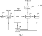
Figure 1 is a block diagram showing a developer system; -
Figure 2 is a representation describing tile-based deferred rendering artefact creation; -
Figure 3 is a block diagram showing a tile-based deferred rendering graphics processor according to embodiments of the claimed invention; -
Figure 4 shows the layout of data on a buffer in the processor ofFigure 3 ; and -
Figure 5 shows a flow-chart explaining the operation of the system ofFigure 1 . - Referring to
Figure 1 , adeveloper system 100 is shown. Thedeveloper system 100 includes the components of the computer on which the software will run. In this specific embodiment, the developer system includes the components of a handheld console and specifically anaudio processor 115, agraphics processor 120, adisplay driver 130 and acentral processing unit 125. In addition to these components, thedeveloper system 100 includes a performance monitor block 110 (a perfmon block) and amemory 105 coupled to theperfmon block 110. In embodiments, the handheld console also includes the perfmon block. However, it is envisaged that the perfmon block in the handheld console will not be operative. - Specifically, the
CPU 125 is connected to thedisplay driver 130, thegraphics processor 120, theperfmon block 110, theaudio processor 115 and thememory 105. Thegraphics processor 120 is additionally connected to thedisplay driver 130 and theperfmon block 110. Finally, theperfmon block 110 is additionally connected to thememory 105, theaudio processor 115 and thedisplay driver 130. These components are connected by data buses as indicated inFigure 1 . It is envisaged that other components, such as a wireless network adapter, will be provided in thedeveloper system 100 and/or the handheld console that are not shown inFigure 1 . - In embodiments of the invention, the
graphics processor unit 120 uses tile-based deferred rendering (referred to as "TBDR" hereinafter) to generate computer graphics. TBDR is a known method for rendering computer graphics and is particularly suited to hand-held consoles. TBDR is described in general with reference toFigure 2 . -
Figure 2 shows animage 200 of afirst rectangle 201 and asecond rectangle 210. In order to draw thefirst rectangle 201, theCPU 125 instructs thegraphics processor 120 to draw both thefirst rectangle 201 and thesecond rectangle 210. This instruction is performed using "batches". In other words, thefirst rectangle 201 is a first batch of work to be drawn by thegraphics processor 120. This first batch of work is given a unique identifier in theimage 200 by thegraphics processor 110. Similarly, thesecond rectangle 210 is a second batch of work to be drawn by thegraphics processor 120. This second batch of work is given a unique identifier in theimage 200 by thegraphics processor 110. The batch identifier is generated by thegraphics processor 120 when instructed to draw the first and second rectangle by theCPU 125. This allocation takes place at the start of the geometry phase. In order to generate the unique identifier, thegraphics processor 120 increments the identifier upon receiving each new batch. Typically, the unique identifier is seeded to be "0" at the start of every frame. To ensure that the identifier is unique within the frame, the size of the identifier has to be large enough to ensure that the unique identifier is unique within the frame. - The
CPU 125, as part of the batch process provides thegraphics processor 120 with polygon information required to draw bothrectangles first rectangle 201 and thesecond rectangle 210. In the Figure, these polygons are triangles although the invention is not so limited and any polygon can be used as appreciated. Associated with each polygon are colour, shading and texture information. - When generating the
image 200 on the screen, thegraphics processor 120 first splits the screen into "tiles". Atile 205 is a block of pixels in some embodiments, although the invention is not so limited. For example, inFigure 2 , each tile is a block of pixels which is 4 pixels wide (i.e. 4 pixels in the x-direction) and 4 pixels high (i.e. 4 pixels in the y-direction), although other appropriate sizes such as 16 pixels wide and 16 pixels high are also envisaged. Additionally, the tiles may be single pixels or may even be non-uniform. For example, a tile may be 16 pixels wide and only 4 pixels high. It should be noted here that the allocation of the tile is made when the image is to be rendered. In other words, in one image on the screen each tile may be 4 pixels wide and 4 pixels high but in the next image on the screen, each tile may be 16 pixels wide and 16 pixels high. - Each tile is given a unique identifier. This enables the
graphics processor 120 to identify each tile uniquely in the image. In embodiments, the tiles are given an identifier based on the location, in terms of x,y co-ordinates of one point of the tile on the screen. So, in the example ofFigure 2 , the co-ordinates of point 206' is the point oftile 206 that determines the identifier of the tile. As the tile is 4 pixels wide and 4 pixels high, point 206' is located at position (4,4) on the screen - where the top left corner of the image is (0,0). Thus,tile 206 is given the identifier tile(4,4). Similarly, point 207' is located at (8,4) and so the identifier oftile 207 is tile(8,4). This identification process is carried out for each tile in theimage 200. It should be noted that the invention is not limited to this numbering system, and any system enabling any tile to be uniquely identified in the image is envisaged. - There are two distinct phases in embodiments of the present invention; the geometry phase and the rasterisation phase. The division of the screen into tiles takes place during the geometry phase, and the drawing of the two rectangles takes place during the rasterisation phase.
- After the screen has been divided into tiles, the
graphics processor 120 will draw the first andsecond rectangle CPU 125. This is illustrated inFigure 2 . For clarity, the polygons are triangles and only afirst triangle 202 and asecond triangle 225 are highlighted. The triangles are defined by their three vertices. So, for example,triangle 202 will be defined by the pixel positions ABC. The vertices of the triangle provide a unique identifier for each triangle. - With regard to
triangle 225, it should be noted that two areas of thetriangle 220 and 220' are located underneath other triangles. This is indicated in the Figures by dashed lines. In other words,areas 220 and 220' will not be visible in theimage 200. - The
graphics processor 120 determines which tiles contain which triangle. This can be achieved because the vertices of each triangle are known and the geometry of each tile is also known. This means that thegraphics processor 120 knows for each batch which tiles are to be used and determines for each tile the triangles that are to be placed in that tile, as well as the colour and texture information for each triangle. The above is the geometry phase of rendering in TBDR..Thegraphics processor 120 then sorts the triangles so that only areas that are to appear on the screen will ultimately be rendered. In other words, as theareas 220 and 220' of thetriangle 225 are located underneath other triangles (and so would not be visible on the screen),areas 220 and 220' will not be rendered on the screen. This is part of the rasterisation phase of rendering in TBDR, although it could be carried out as part of the geometry phase. -
Figure 3 shows a block diagram of thegraphics processor 120. Thegraphics processor 120, in embodiments of the invention, has ageometry phase block 305 connected to anintermediate buffer 310 by a bus. Theintermediate buffer 310 is connected to a rasterisation phase block 315 again by a bus. - After the
graphics processor 120 has completed the geometry phase of TBDR, the acquired information is fed into theintermediate buffer 310 for storage. Within theintermediate buffer 310, the data is stored in a manner shown inFigure 4 . As is seen inFigure 4 , for each tile ID the polygons making up that tile are defined. Additionally, for each identified polygon, the batch ID, colour, texture and shading data are stored. - In order to generate the
image 200 on the screen, relevant information stored in theintermediate buffer 310 is retrieved by therasterisation phase block 315. Therasterisation phase block 315 does not draw each batch. Instead therasterisation block 315 draws each tile. In order to draw a tile, therasterisation phase block 315 firstly determines the tile upon which it is about to work. Therasterisation phase block 315 uses the obtained polygon information to draw the visible areas of the polygon. The appropriate colour, shading and texture are applied to the visible areas of that polygon. - Although each tile can be drawn in sequence (i.e. the first tile is drawn and then the second tile is drawn), this may not be the case. In some cases, "time slicing" takes place. Time slicing is the process by which the
graphics processor 120 draws a tile out of sequence. This can occur if thegraphics processor 120 starts drawing a tile but requires other information to complete the drawing of the tile currently being drawn. Typically, this may be some texture data from theCPU 125. Rather than waiting for that other information to complete the drawing of that tile, thegraphics processor 120 starts drawing another tile. - After a tile is drawn, it is moved from the
rasterisation phase block 315 of thegraphics processor 120 to thedisplay driver 130 for storage in an image buffer (not shown). After all the tiles have been completed, and stored in the image buffer of thedisplay driver 130, theimage 200 is output to a screen. - As noted earlier, during the development stage of a piece of software it is necessary to analyse the performance of different processors in the system when running the software. This analysis helps improve the speed at which the software is executed and also ensures that the software is stable (i.e. does not cause the system to fail). Accordingly, performance data may be data indicating that the processor is running at a certain capacity, or indicating that the processor has crashed. This means that the
Perfmon block 110 obtains data from each processor in thesystem 100. However, for clarity, only the interaction of thegraphics processor 120 with thePerfmon block 110 will now be described. In other words, the manner in which theperfmon block 110 determines the performance of thegraphics processor 120 when generatingimage 200 will now be described. - In order to determine the amount of time the graphics processor takes to process a particular task, the
perfmon block 110 receives a number of count signals from thegraphics processor 120. In embodiments, thegraphics processor 120 has a number of count signals issued therefrom and theperfmon block 110 has a corresponding number of counters included therein (i.e. one counter in theperfmon block 110 for each count signal from the graphics processor). However, for the following, only one count signal from thegraphics processor 120 and one counter in theperfmon block 110 will be described for convenience. - The count signal from the graphics processor is either a 1 or a 0 and cycles between the two values at the same frequency as the clock frequency of the
graphics processor unit 120. This count signal is fed into one 16 bit counter located within theperfmon block 110. The counter within theperfmon block 110 count each time the count signal from thegraphics processor 120 goes to 1. Additionally fed into theperfmon block 110 from thegraphics processor 120 is information identifying the task that thegraphics processor 120 is currently performing. - This task is the batch ID and the tile ID currently being performed by the
graphics processor 120. The batch ID and tile ID are output to theperfmon block 110 alongside the counter signal. As the batch ID and tile ID are output at the same frequency as the counter signal, theperfmon block 110 is able to determine how long each task performed by thegraphics processor 120 takes. - The interaction of the
perfmon block 110 is described with reference to theflow chart 500 ofFigure 5 . - When
image 200 is to be drawn, theperfmon block 110 begins atstep 501. - The
CPU 125 issues two batch instructions to the graphics processor atstep 502. As noted above, one batch instruction relates to thefirst rectangle 201 and the second batch instruction relates to thesecond rectangle 210. Each batch instruction includes the polygon information required to draw the first and second rectangle respectively. - The
graphics processor 120 begins the geometry phase of the image processing atstep 503. In order to perform the geometry phase of the image processing, thegraphics processor 120 begins processing the first batch instruction atstep 504. In other words, thegraphics processor 120 begins the geometry phase processing of thefirst rectangle 201. This will be apparent to theperfmon block 110 because the batch ID output thereto will indicate the batch ID of thefirst rectangle 201. As the counter in the perfmon block 110 counts the number of times the count signal in thegraphics processor 120 goes to 1 (i.e. the number of clock cycles used by thegraphics processor 120 in processing the first batch in the geometry phase), theperfmon block 110 output can thus be used to determine the length of time required by thegraphics processor 120 to process the first batch in the geometry phase. - The tiles in which the
first rectangle 201 will be drawn, and associated polygons, are determined (step 505). This concludes the geometry phase for the first batch (i.e. the first rectangle 201). It is decided whether this batch is the last batch that needs geometry phase processing (step 507). In this case, there is a second batch to process (i.e. the second rectangle 210). - Therefore, in
step 506 the batch ID that is processed is changed. This change in batch ID, for example, means that a valid "condition" is met. Thus, the value of the counter within theperfmon block 110 for this batch ID, along with the batch ID itself, is output to thememory 105. The counter within theperfmon block 110 is then reset. Although the batch ID is given as an example condition, the invention is not so limited and any arbitrary condition is also envisaged. - The second batch (i.e. second rectangle) is then subjected to the geometry phase processing as explained above.
- After the geometry phase processing on the second batch has taken place, there are no further batches to be processed in the geometry phase of this embodiment. Thus, the answer to the question at
step 507 is "yes". - In
step 508, thegraphics processor 210 then commences the rasterisation phase. In order to do this, the first tile is rasterised (step 509). During this rasterisation, the counter signal and the tile ID is output to theperfmon block 110. This again indicates the length of time taken to rasterise the first tile. After the first tile has been rasterised a check is carried out atstep 510 to determine if this rasterised tile is the final tile to be processed. As the tile is not the final tile to be rasterised then the tile ID is incremented and the next tile is rasterised (step 511). The incrementing of the tile ID to generate the new tile ID is a valid "condition" and so the value of the counter in theperfmon block 110, along with the tile ID is output to thememory 105 and stored in association therein. The counter is then reset. By storing the tile ID and the batch ID in association with the number of counter cycles for each, it is possible to determine the length of time it takes for the graphics processor to process the particular tile and batch. - If at
step 510 the check indicates that the tile that had just been rasterised is the final tile, then the process ends (step 512). - The above notes that the counter value is output from
perfmon block 110 when a certain condition is met. In embodiments, a timestamp is also provided to theperfmon block 110. The timestamp is obtained from a system-wide clock which defines the time at which the counter value and the batch ID and/or tile ID was output to theperfmon block 110. This timestamp identifies the state of thegraphics processor 120 at the time specified by the timestamp. Moreover, by using a timestamp obtained from a system-wide clock, it is also possible that other processors can also output performance monitoring data to theperfmon block 110 and that it is possible to associate the performance of other processors (such as the audio processor) with the performance of thegraphics processor 120 at that particular time. This improves the performance analysis of the development system. - Therefore, in the
memory 105 are stored the details of each task carried out by thegraphics processor 120. In this case, the task includes the geometry phase and separately the rasterisation phase. The details of the tasks are stored in association with the length of time taken for that particular task. Also, in the memory the "condition" which triggered the sampling of the performance data is stored in thememory 105. Further, the timestamp when the performance data was sent tomemory 105 is stored inmemory 105. This information can be retrieved by theCPU 125. - By outputting the performance data from the
perfmon block 110 when the tile ID and/or batch ID changes means that memory bandwidth is efficiently used. To put it another way, by outputting the performance data from theperfmon block 110 when the "condition" of the data being collated changes means that memory bandwidth is efficiently used. - This is because, as noted above, in other systems the data being collated is output from the
perfmon block 110 is output at a fixed sample rate. Therefore, in order to ensure that performance data for each tile and/or batch is output using these other systems would require a very high sample rate. This is because some tiles and batches are very easy to process and so take a fraction of the time to process as more complicated tiles and/or batches. Thus, in order to increase the chance of the information relating to these simpler tiles and/or batches being collected, the sample rate would have to be high. However, as noted earlier, a high sample rate means that memory bandwidth, and CPU processing requirements are increased. Additionally, as the sampled data needs to be stored before being processed, this increases the size ofmemory 105 consumed. - As noted above, the
graphics processor 120 may render graphics using a "time slice" technique. This technique allows thegraphics processor 120 to stop processing one tile whilst waiting for data from another part of the system and commence processing a different tile. In embodiments of the invention, this means that, as the tile ID has changed, there will be at least two entries in thememory 105 for such tile. By differentiating these entries in the memory is useful. If the data from the other part of the system takes a proportionally long time to obtain, then it is possible for the developer to identify this and take corrective action. For instance, the developer could identify that the performance of the other part of the system is not adequate, or that a different texture be used or the like. - Moreover, in images where very simple batches and tiles are to be rendered, the speed at which the performance data is sampled from the
perfmon block 110 will be very high. This is because the rate at which the tile ID and/or batch ID changes is very high. In order to further reduce the memory bandwidth used, an upper limit of sample data is imposed in embodiments. This bandwidth will depend, to some extent, on the number of counters used. If there are a large number of counters written to memory, then a lower upper limit is used to prevent the bandwidth being flooded. As conditional sampling takes place (which reduces the memory bandwidth requirements), this upper limit is higher than the upper limit in known fixed sampling systems. - In the foregoing embodiments, at least one counter in the
perfmon block 110 is used. Counters have a "wrap" condition. In other words, when the counter has reached the maximum count, the counter is reset and begins counting again. In order to ensure that the performance data is not lost when the counter "wraps", one other condition in which the performance data is output to thememory 105 is when the counter wraps. This ensures that the performance data is not lost and increases the accuracy of such data. - Additionally, it should be noted here that in embodiments, the performance data is only output when it is valid data. The performance data is valid when all the bits defined in an "On Condition Validity Mask" are matched. However, other valid and non-valid conditions are also envisaged. For example, a tile processing cycle is only valid when the
graphics processor 210 is currently processing a tile. Moreover, one further condition in which the performance data is output is when the valid condition changes from "valid" to "not-valid" or vice versa. - Although the foregoing relates to measuring the performance of the
graphics processor 120, the invention is not limited. Indeed, any processor performance can be measured. This is indicated by thedisplay driver 130 and theaudio processor 115 also being connected to theperfmon block 110 inFigure 1 . - In embodiments of the invention, the
graphics processor 120 is a tile based deferred rendering processor. This is described inFigure 3 . - As noted hereinbefore, the
graphics processor 120 comprises ageometry phase block 305 connected to abuffer 310. Thebuffer 310 is connected to therasterisation phase block 315. In embodiments, thegeometry phase block 305 and therasterisation phase block 315 are hardware. Thebuffer 310 stores the batch ID and the tile ID to which the polygon is associated. In other words, thebuffer 310 details the identity of each tile used in each batch. This is particularly useful. - As noted before, in tile based deferred rendering, the workload during the geometry phase is the batch. However, during the rasterisation phase, the workload is the tile. Therefore, by storing the additional data in the
buffer 310, if during performance analysis it is identified that a particular tile is causing the rendering to stall, or even causing the system as a whole to crash, then it is possible to identify the batch which is associated with the performance issue. This means that it is possible for the developer to address this issue in the user application program or graphics application program domain. - Additionally, it should be noted here that the
CPU 125 can access the data stored in thebuffer 310. Indeed, the data stored in thebuffer 310 can be propagated throughout the system in the pipeline. This is useful because the performance of different processors, for example theaudio processor 115, may be affected by different tasks carried out on thegraphics processor 120. So, for example, if the performance of theaudio processor 115 decreases when a certain batch is being processed by thegraphics processor 120, then this can be identified by the developer by having the batch ID propagated throughout thesystem 100. Further, if theCPU 125 crashes, the propagated batch ID is output to a core dump. This allows the developer to analyse whether processing a particular batch caused theCPU 125 to crash. - As a de-bugging feature, the
graphics processor 120 can have data break-points. This means that if one particular memory location, or memory location range of thebuffer 310 ormemory 105 is written to, or read from by thegraphic processor 120, thesystem 100 will stop and relevant operating information will be written to a memory dump for analysis. The parameters for initiating a break point and the relevant operating information are set by the developer. - The foregoing embodiments may be implemented as computer software code. This code will configure a computer to operate in a particular way. The computer software may be embodied as signals which may be stored on a storage medium such as an optical or magnetic recording medium or even on solid state memory. Additionally, or alternatively, the signals and/or code may be stored on a network or may be transferred across a network, such as the Internet or a Local Area Network.
Claims (15)
- A method of determining the performance of a tile based deferred rendering processor (120) when processing a unit of data, using a separate performance monitoring block (110) connected to the processor (120) via a data bus, the method comprising the performance monitoring block implementing the steps of:receiving from the processor, at a clock rate, a binary count signal indicating that the processor is processing the unit of data;counting the number of received count signals;receiving from the processor an identifier used by the processor for identifying the unit of data being processed;detecting whether the identifier changes; and if so,outputting the identifier of the unit of data being processed and the counted number of the received count signals.
- A method according to claim 1, comprising the steps of:outputting the identifier of the unit of the data being processed and the counted number of the received count signals to a memory; andproviding an upper threshold on the rate of output.
- A method according to claim 2, wherein the upper threshold is determined in accordance with the bandwidth of the memory.
- A method according to any preceding claim, comprising setting a validity identifier, the validity identifier being set in accordance with a comparison between the counted number and a validity criterion indicating that such counted number is valid; and
outputting the count number in the event of both the identity changing and upon a positive comparison between the count number and the validity criterion. - A method according to any preceding claim wherein the identifier and counted signal is output when the counter wraps.
- A method according to any preceding claim, wherein the change of identity is:i) changing of the tile identity; orii) changing of the batch identity.
- A performance monitoring apparatus (110) for determining the performance of a separate tile based deferred rendering processor (120) when processing a unit of data, the performance monitoring apparatus being connected to the processor (120) via a data bus and comprising:a receiving device operable to receive from the processor, at a clock rate, a binary count signal indicating that the graphics processor is processing the unit of data;a counter operable to count the number of received count signals;a receiving device operable to receive from the processor an identifier used by the graphics processor for identifying the unit of data being processed;a detecting device operable to detect whether the identifier changes; and if so,an outputting device operable to output the identifier of the unit of data being processed and the counted number of the received count signals.
- An apparatus according to claim 7, wherein the outputting device is operable to output the identifier of the unit of the data being processed and the counted number of received count signals to a memory; and
a providing device operable to provide an upper threshold on the rate of output. - An apparatus according to claim 8, wherein the upper threshold is determined in accordance with the bandwidth of the memory.
- An apparatus according to any one of claims 7, 8 or 9, comprising a setting device operable to set a validity identifier, the validity identifier being set in accordance with a comparison between the count number and a validity criterion indicating that such count number is valid; and
the outputting device is operable to output the count number in the event of both the identity changes and upon a positive comparison between the count number and the validity criterion. - An apparatus according to any one of claims 7 to 10, wherein, the identifier and counter value are output when the counter wraps.
- An apparatus according to anyone of claims 7 to 11, wherein the condition isi) changing of the tile identity; orii) changing of the batch identity.
- A computer device comprising:
a display driver operable to control a display;
a central processing unit operable to control the display driver;
a tile based deferred rendering processor coupled to both the display driver and the central processing unit; and
an apparatus according to any one of claims 7 to 12. - A computer program containing computer readable instructions which, when loaded onto a computer, configure the computer to perform the method according to any one of claims 1 to 6.
- A computer readable storage medium configured to store the computer program of claim 14 therein or thereon.
Applications Claiming Priority (4)
| Application Number | Priority Date | Filing Date | Title |
|---|---|---|---|
| GB0916095A GB0916095D0 (en) | 2009-09-14 | 2009-09-14 | A method of determining the state of a tile based deferred rendering processor |
| GB0916097A GB0916097D0 (en) | 2009-09-14 | 2009-09-14 | A method and apparatus for determining processor performance |
| GB0922452.8A GB2473513B (en) | 2009-09-14 | 2009-12-22 | A method and apparatus for determining processor performance |
| PCT/GB2010/051530 WO2011030164A1 (en) | 2009-09-14 | 2010-09-13 | A method and apparatus for determining processor performance |
Publications (2)
| Publication Number | Publication Date |
|---|---|
| EP2476059A1 EP2476059A1 (en) | 2012-07-18 |
| EP2476059B1 true EP2476059B1 (en) | 2018-07-18 |
Family
ID=41717424
Family Applications (2)
| Application Number | Title | Priority Date | Filing Date |
|---|---|---|---|
| EP10760390.4A Active EP2476059B1 (en) | 2009-09-14 | 2010-09-13 | A method and apparatus for determining processor performance |
| EP10776121.5A Active EP2470995B1 (en) | 2009-09-14 | 2010-09-13 | A method of determining the state of a tile based deferred rendering processor and apparatus thereof |
Family Applications After (1)
| Application Number | Title | Priority Date | Filing Date |
|---|---|---|---|
| EP10776121.5A Active EP2470995B1 (en) | 2009-09-14 | 2010-09-13 | A method of determining the state of a tile based deferred rendering processor and apparatus thereof |
Country Status (4)
| Country | Link |
|---|---|
| US (2) | US9342430B2 (en) |
| EP (2) | EP2476059B1 (en) |
| GB (2) | GB2473682B (en) |
| WO (2) | WO2011030165A2 (en) |
Families Citing this family (14)
| Publication number | Priority date | Publication date | Assignee | Title |
|---|---|---|---|---|
| US11016702B2 (en) | 2011-07-27 | 2021-05-25 | Pure Storage, Inc. | Hierarchical event tree |
| US10678619B2 (en) | 2011-07-27 | 2020-06-09 | Pure Storage, Inc. | Unified logs and device statistics |
| US9170868B2 (en) | 2011-07-27 | 2015-10-27 | Cleversafe, Inc. | Identifying an error cause within a dispersed storage network |
| US12099752B2 (en) | 2011-07-27 | 2024-09-24 | Pure Storage, Inc. | Error prediction based on correlation using event records |
| US9030480B2 (en) * | 2012-12-18 | 2015-05-12 | Nvidia Corporation | Triggering performance event capture via pipelined state bundles |
| US9449410B2 (en) | 2013-04-11 | 2016-09-20 | Qualcomm Incorporated | Intra-frame timestamps for tile-based rendering |
| US9305326B2 (en) | 2013-12-26 | 2016-04-05 | Industrial Technology Research Institute | Apparatus and method for tile elimination |
| EP3012737A1 (en) * | 2014-10-24 | 2016-04-27 | Thomson Licensing | Devices and methods for generating elementary geometries |
| US9626733B2 (en) | 2014-11-24 | 2017-04-18 | Industrial Technology Research Institute | Data-processing apparatus and operation method thereof |
| GB2555586B (en) | 2016-10-31 | 2019-01-02 | Imagination Tech Ltd | Performance profiling in a graphics unit |
| KR102637736B1 (en) | 2017-01-04 | 2024-02-19 | 삼성전자주식회사 | Graphics processing method and system |
| CN106844152B (en) * | 2017-01-17 | 2019-10-29 | 清华大学 | Bank's background task runs the correlation analysis and device of batch time |
| WO2019225734A1 (en) | 2018-05-24 | 2019-11-28 | 株式会社 Preferred Networks | Rendering device, learning device, rendering method, and program |
| US12360751B2 (en) | 2023-04-24 | 2025-07-15 | International Business Machines Corporation | Automated product workflow usability assessment |
Family Cites Families (29)
| Publication number | Priority date | Publication date | Assignee | Title |
|---|---|---|---|---|
| JPS61117633A (en) * | 1984-10-19 | 1986-06-05 | Fujitsu Ltd | Capture ratio measuring system |
| US5388206A (en) | 1992-11-13 | 1995-02-07 | The University Of North Carolina | Architecture and apparatus for image generation |
| US6084591A (en) * | 1997-04-29 | 2000-07-04 | Ati Technologies, Inc. | Method and apparatus for deferred video rendering |
| US6148396A (en) * | 1997-11-26 | 2000-11-14 | Compaq Computer Corporation | Apparatus for sampling path history in a processor pipeline |
| US6480205B1 (en) | 1998-07-22 | 2002-11-12 | Nvidia Corporation | Method and apparatus for occlusion culling in graphics systems |
| US6771264B1 (en) * | 1998-08-20 | 2004-08-03 | Apple Computer, Inc. | Method and apparatus for performing tangent space lighting and bump mapping in a deferred shading graphics processor |
| US6782432B1 (en) * | 2000-06-30 | 2004-08-24 | Intel Corporation | Automatic state savings in a graphics pipeline |
| US20020063715A1 (en) * | 2000-11-30 | 2002-05-30 | Silicon Graphics, Inc. | System, method, and computer program product for capturing a visualization session |
| US6880072B1 (en) * | 2001-05-08 | 2005-04-12 | Lsi Logic Corporation | Pipelined processor and method using a profile register storing the return from exception address of an executed instruction supplied by an exception program counter chain for code profiling |
| US6943800B2 (en) * | 2001-08-13 | 2005-09-13 | Ati Technologies, Inc. | Method and apparatus for updating state data |
| US6809732B2 (en) * | 2002-07-18 | 2004-10-26 | Nvidia Corporation | Method and apparatus for generation of programmable shader configuration information from state-based control information and program instructions |
| US6886081B2 (en) * | 2002-09-17 | 2005-04-26 | Sun Microsystems, Inc. | Method and tool for determining ownership of a multiple owner lock in multithreading environments |
| TW589545B (en) * | 2002-10-25 | 2004-06-01 | Cyberlink Corp | Computer-executable method for recovering video rendering |
| US7143396B2 (en) * | 2002-11-06 | 2006-11-28 | Sun Microsystems, Inc. | System and method for measuring code segment performance |
| WO2004072907A1 (en) | 2003-02-13 | 2004-08-26 | Koninklijke Philips Electronics N.V. | Computer graphics system and method for rendering a computer graphic image |
| US6751282B1 (en) * | 2003-03-13 | 2004-06-15 | National Semiconductor Corporation | Signal active percentage monitor |
| US7095416B1 (en) | 2003-09-22 | 2006-08-22 | Microsoft Corporation | Facilitating performance analysis for processing |
| US20060059468A1 (en) * | 2004-09-10 | 2006-03-16 | Sony Computer Entertainment Inc. | Methods and systems for graphically navigating within a debugger program |
| GB2444863B (en) * | 2005-12-05 | 2008-10-08 | Arm Norway As | Method of and apparatus for processing graphics |
| US7600155B1 (en) * | 2005-12-13 | 2009-10-06 | Nvidia Corporation | Apparatus and method for monitoring and debugging a graphics processing unit |
| US20070139421A1 (en) * | 2005-12-21 | 2007-06-21 | Wen Chen | Methods and systems for performance monitoring in a graphics processing unit |
| US7778800B2 (en) * | 2006-08-01 | 2010-08-17 | Nvidia Corporation | Method and system for calculating performance parameters for a processor |
| GB2440667B (en) * | 2006-08-01 | 2011-10-26 | Nvidia Corp | A method and system for debugging a graphics pipeline subunit |
| US20080222456A1 (en) * | 2007-03-05 | 2008-09-11 | Angela Richards Jones | Method and System for Implementing Dependency Aware First Failure Data Capture |
| GB0723536D0 (en) * | 2007-11-30 | 2008-01-09 | Imagination Tech Ltd | Multi-core geometry processing in a tile based rendering system |
| US7886202B2 (en) | 2008-02-27 | 2011-02-08 | International Business Machines Corporation | System and methods for recording, displaying, and reconstructing computer-based system and user events |
| US8933943B2 (en) * | 2008-04-30 | 2015-01-13 | Intel Corporation | Technique for performing load balancing for parallel rendering |
| GB2461900B (en) * | 2008-07-16 | 2012-11-07 | Advanced Risc Mach Ltd | Monitoring graphics processing |
| GB2466078B (en) * | 2008-12-15 | 2013-11-13 | Advanced Risc Mach Ltd | Apparatus and method for tracing activities of a shader program executed on shader circuitry of a data processing apparatus |
-
2009
- 2009-12-22 GB GB0922453A patent/GB2473682B/en active Active
- 2009-12-22 GB GB0922452.8A patent/GB2473513B/en active Active
-
2010
- 2010-09-13 WO PCT/GB2010/051531 patent/WO2011030165A2/en not_active Ceased
- 2010-09-13 US US13/395,794 patent/US9342430B2/en active Active
- 2010-09-13 WO PCT/GB2010/051530 patent/WO2011030164A1/en not_active Ceased
- 2010-09-13 EP EP10760390.4A patent/EP2476059B1/en active Active
- 2010-09-13 US US13/395,745 patent/US9547577B2/en active Active
- 2010-09-13 EP EP10776121.5A patent/EP2470995B1/en active Active
Non-Patent Citations (1)
| Title |
|---|
| "INTERNAL PROCESSOR STATE PERFORMANCE MONITORING", RESEARCH DISCLOSURE, MASON PUBLICATIONS, HAMPSHIRE, GB, no. 335, 1 March 1992 (1992-03-01), pages 221, XP000301130, ISSN: 0374-4353 * |
Also Published As
| Publication number | Publication date |
|---|---|
| US9547577B2 (en) | 2017-01-17 |
| GB2473513B (en) | 2012-02-01 |
| GB0922452D0 (en) | 2010-02-03 |
| GB0922453D0 (en) | 2010-02-03 |
| EP2476059A1 (en) | 2012-07-18 |
| US20120236011A1 (en) | 2012-09-20 |
| WO2011030164A9 (en) | 2017-12-07 |
| WO2011030164A1 (en) | 2011-03-17 |
| EP2470995A2 (en) | 2012-07-04 |
| GB2473513A (en) | 2011-03-16 |
| WO2011030165A3 (en) | 2011-04-28 |
| US9342430B2 (en) | 2016-05-17 |
| GB2473682B (en) | 2011-11-16 |
| WO2011030165A2 (en) | 2011-03-17 |
| EP2470995B1 (en) | 2014-03-05 |
| US20120232845A1 (en) | 2012-09-13 |
| GB2473682A (en) | 2011-03-23 |
Similar Documents
| Publication | Publication Date | Title |
|---|---|---|
| US9547577B2 (en) | Method and apparatus for determining processor performance | |
| EP2438576B1 (en) | Displaying a visual representation of performance metrics for rendered graphics elements | |
| CN110362483B (en) | Performance data acquisition method, device, equipment and storage medium | |
| CN103455396B (en) | The method of testing of electronic equipment hardware performance and device | |
| CN107885645B (en) | Method and device for calculating rendering duration of first screen of page and electronic equipment | |
| CA2880345C (en) | Hit testing method and apparatus | |
| CN108986012B (en) | Shader parser | |
| CN108765539B (en) | OpenGLES-based image rendering method, device, equipment and storage medium | |
| CN110825731A (en) | Data storage method and device, electronic equipment and storage medium | |
| US6530031B1 (en) | Method and apparatus for timing duration of initialization tasks during system initialization | |
| CN112445855A (en) | Visual analysis method and visual analysis device for graphic processor chip | |
| US7561161B2 (en) | Quantitative measure of a video interface | |
| CN107273124A (en) | The processing method of running software performance information, apparatus and system | |
| CN112559102A (en) | Task operation time sequence display method and device, electronic equipment and storage medium | |
| CN110930499B (en) | 3D data processing method and device | |
| CN114706581B (en) | Image analysis methods, apparatus, computer equipment, and storage media | |
| CN109976741B (en) | Computer resource management method and device, intelligent terminal and storage medium | |
| WO2012056569A1 (en) | Performance measurement method, performance measurement device, and performance measurement program | |
| JP2715904B2 (en) | Computer system performance evaluation device | |
| EP4592837A1 (en) | Method and device for automatically scrolling and capturing a dialogue box running on an android-based portable terminal | |
| CN113515354A (en) | A unified processing system and method based on environmental context consistency | |
| CN118708445B (en) | Real-time monitoring and debugging method, device and electronic equipment for RISC-V chip | |
| CN114398285B (en) | Code detection method, device, electronic device and storage medium | |
| CN114090523B (en) | Electronic device, and node parsing method and medium for XML file thereof | |
| US20050071613A1 (en) | Instruction mix monitor |
Legal Events
| Date | Code | Title | Description |
|---|---|---|---|
| PUAI | Public reference made under article 153(3) epc to a published international application that has entered the european phase |
Free format text: ORIGINAL CODE: 0009012 |
|
| 17P | Request for examination filed |
Effective date: 20120329 |
|
| AK | Designated contracting states |
Kind code of ref document: A1 Designated state(s): AL AT BE BG CH CY CZ DE DK EE ES FI FR GB GR HR HU IE IS IT LI LT LU LV MC MK MT NL NO PL PT RO SE SI SK SM TR |
|
| DAX | Request for extension of the european patent (deleted) | ||
| 17Q | First examination report despatched |
Effective date: 20130930 |
|
| RAP1 | Party data changed (applicant data changed or rights of an application transferred) |
Owner name: SONY INTERACTIVE ENTERTAINMENT EUROPE LIMITED |
|
| GRAJ | Information related to disapproval of communication of intention to grant by the applicant or resumption of examination proceedings by the epo deleted |
Free format text: ORIGINAL CODE: EPIDOSDIGR1 |
|
| GRAP | Despatch of communication of intention to grant a patent |
Free format text: ORIGINAL CODE: EPIDOSNIGR1 |
|
| STAA | Information on the status of an ep patent application or granted ep patent |
Free format text: STATUS: EXAMINATION IS IN PROGRESS |
|
| GRAP | Despatch of communication of intention to grant a patent |
Free format text: ORIGINAL CODE: EPIDOSNIGR1 |
|
| STAA | Information on the status of an ep patent application or granted ep patent |
Free format text: STATUS: GRANT OF PATENT IS INTENDED |
|
| INTG | Intention to grant announced |
Effective date: 20180205 |
|
| GRAS | Grant fee paid |
Free format text: ORIGINAL CODE: EPIDOSNIGR3 |
|
| GRAA | (expected) grant |
Free format text: ORIGINAL CODE: 0009210 |
|
| STAA | Information on the status of an ep patent application or granted ep patent |
Free format text: STATUS: THE PATENT HAS BEEN GRANTED |
|
| AK | Designated contracting states |
Kind code of ref document: B1 Designated state(s): AL AT BE BG CH CY CZ DE DK EE ES FI FR GB GR HR HU IE IS IT LI LT LU LV MC MK MT NL NO PL PT RO SE SI SK SM TR |
|
| REG | Reference to a national code |
Ref country code: GB Ref legal event code: FG4D |
|
| REG | Reference to a national code |
Ref country code: CH Ref legal event code: EP |
|
| REG | Reference to a national code |
Ref country code: IE Ref legal event code: FG4D |
|
| REG | Reference to a national code |
Ref country code: FR Ref legal event code: PLFP Year of fee payment: 9 |
|
| REG | Reference to a national code |
Ref country code: AT Ref legal event code: REF Ref document number: 1020071 Country of ref document: AT Kind code of ref document: T Effective date: 20180815 |
|
| REG | Reference to a national code |
Ref country code: DE Ref legal event code: R096 Ref document number: 602010052012 Country of ref document: DE |
|
| REG | Reference to a national code |
Ref country code: NL Ref legal event code: FP |
|
| REG | Reference to a national code |
Ref country code: LT Ref legal event code: MG4D |
|
| REG | Reference to a national code |
Ref country code: AT Ref legal event code: MK05 Ref document number: 1020071 Country of ref document: AT Kind code of ref document: T Effective date: 20180718 |
|
| PG25 | Lapsed in a contracting state [announced via postgrant information from national office to epo] |
Ref country code: LT Free format text: LAPSE BECAUSE OF FAILURE TO SUBMIT A TRANSLATION OF THE DESCRIPTION OR TO PAY THE FEE WITHIN THE PRESCRIBED TIME-LIMIT Effective date: 20180718 Ref country code: FI Free format text: LAPSE BECAUSE OF FAILURE TO SUBMIT A TRANSLATION OF THE DESCRIPTION OR TO PAY THE FEE WITHIN THE PRESCRIBED TIME-LIMIT Effective date: 20180718 Ref country code: PL Free format text: LAPSE BECAUSE OF FAILURE TO SUBMIT A TRANSLATION OF THE DESCRIPTION OR TO PAY THE FEE WITHIN THE PRESCRIBED TIME-LIMIT Effective date: 20180718 Ref country code: IS Free format text: LAPSE BECAUSE OF FAILURE TO SUBMIT A TRANSLATION OF THE DESCRIPTION OR TO PAY THE FEE WITHIN THE PRESCRIBED TIME-LIMIT Effective date: 20181118 Ref country code: BG Free format text: LAPSE BECAUSE OF FAILURE TO SUBMIT A TRANSLATION OF THE DESCRIPTION OR TO PAY THE FEE WITHIN THE PRESCRIBED TIME-LIMIT Effective date: 20181018 Ref country code: AT Free format text: LAPSE BECAUSE OF FAILURE TO SUBMIT A TRANSLATION OF THE DESCRIPTION OR TO PAY THE FEE WITHIN THE PRESCRIBED TIME-LIMIT Effective date: 20180718 Ref country code: GR Free format text: LAPSE BECAUSE OF FAILURE TO SUBMIT A TRANSLATION OF THE DESCRIPTION OR TO PAY THE FEE WITHIN THE PRESCRIBED TIME-LIMIT Effective date: 20181019 Ref country code: NO Free format text: LAPSE BECAUSE OF FAILURE TO SUBMIT A TRANSLATION OF THE DESCRIPTION OR TO PAY THE FEE WITHIN THE PRESCRIBED TIME-LIMIT Effective date: 20181018 Ref country code: SE Free format text: LAPSE BECAUSE OF FAILURE TO SUBMIT A TRANSLATION OF THE DESCRIPTION OR TO PAY THE FEE WITHIN THE PRESCRIBED TIME-LIMIT Effective date: 20180718 |
|
| PG25 | Lapsed in a contracting state [announced via postgrant information from national office to epo] |
Ref country code: AL Free format text: LAPSE BECAUSE OF FAILURE TO SUBMIT A TRANSLATION OF THE DESCRIPTION OR TO PAY THE FEE WITHIN THE PRESCRIBED TIME-LIMIT Effective date: 20180718 Ref country code: LV Free format text: LAPSE BECAUSE OF FAILURE TO SUBMIT A TRANSLATION OF THE DESCRIPTION OR TO PAY THE FEE WITHIN THE PRESCRIBED TIME-LIMIT Effective date: 20180718 Ref country code: HR Free format text: LAPSE BECAUSE OF FAILURE TO SUBMIT A TRANSLATION OF THE DESCRIPTION OR TO PAY THE FEE WITHIN THE PRESCRIBED TIME-LIMIT Effective date: 20180718 |
|
| REG | Reference to a national code |
Ref country code: DE Ref legal event code: R097 Ref document number: 602010052012 Country of ref document: DE |
|
| PG25 | Lapsed in a contracting state [announced via postgrant information from national office to epo] |
Ref country code: IT Free format text: LAPSE BECAUSE OF FAILURE TO SUBMIT A TRANSLATION OF THE DESCRIPTION OR TO PAY THE FEE WITHIN THE PRESCRIBED TIME-LIMIT Effective date: 20180718 Ref country code: MC Free format text: LAPSE BECAUSE OF FAILURE TO SUBMIT A TRANSLATION OF THE DESCRIPTION OR TO PAY THE FEE WITHIN THE PRESCRIBED TIME-LIMIT Effective date: 20180718 Ref country code: EE Free format text: LAPSE BECAUSE OF FAILURE TO SUBMIT A TRANSLATION OF THE DESCRIPTION OR TO PAY THE FEE WITHIN THE PRESCRIBED TIME-LIMIT Effective date: 20180718 Ref country code: ES Free format text: LAPSE BECAUSE OF FAILURE TO SUBMIT A TRANSLATION OF THE DESCRIPTION OR TO PAY THE FEE WITHIN THE PRESCRIBED TIME-LIMIT Effective date: 20180718 Ref country code: RO Free format text: LAPSE BECAUSE OF FAILURE TO SUBMIT A TRANSLATION OF THE DESCRIPTION OR TO PAY THE FEE WITHIN THE PRESCRIBED TIME-LIMIT Effective date: 20180718 Ref country code: CZ Free format text: LAPSE BECAUSE OF FAILURE TO SUBMIT A TRANSLATION OF THE DESCRIPTION OR TO PAY THE FEE WITHIN THE PRESCRIBED TIME-LIMIT Effective date: 20180718 |
|
| REG | Reference to a national code |
Ref country code: CH Ref legal event code: PL |
|
| PLBE | No opposition filed within time limit |
Free format text: ORIGINAL CODE: 0009261 |
|
| STAA | Information on the status of an ep patent application or granted ep patent |
Free format text: STATUS: NO OPPOSITION FILED WITHIN TIME LIMIT |
|
| PG25 | Lapsed in a contracting state [announced via postgrant information from national office to epo] |
Ref country code: SK Free format text: LAPSE BECAUSE OF FAILURE TO SUBMIT A TRANSLATION OF THE DESCRIPTION OR TO PAY THE FEE WITHIN THE PRESCRIBED TIME-LIMIT Effective date: 20180718 Ref country code: SM Free format text: LAPSE BECAUSE OF FAILURE TO SUBMIT A TRANSLATION OF THE DESCRIPTION OR TO PAY THE FEE WITHIN THE PRESCRIBED TIME-LIMIT Effective date: 20180718 Ref country code: DK Free format text: LAPSE BECAUSE OF FAILURE TO SUBMIT A TRANSLATION OF THE DESCRIPTION OR TO PAY THE FEE WITHIN THE PRESCRIBED TIME-LIMIT Effective date: 20180718 |
|
| REG | Reference to a national code |
Ref country code: BE Ref legal event code: MM Effective date: 20180930 |
|
| 26N | No opposition filed |
Effective date: 20190423 |
|
| REG | Reference to a national code |
Ref country code: IE Ref legal event code: MM4A |
|
| PG25 | Lapsed in a contracting state [announced via postgrant information from national office to epo] |
Ref country code: LU Free format text: LAPSE BECAUSE OF NON-PAYMENT OF DUE FEES Effective date: 20180913 |
|
| PG25 | Lapsed in a contracting state [announced via postgrant information from national office to epo] |
Ref country code: IE Free format text: LAPSE BECAUSE OF NON-PAYMENT OF DUE FEES Effective date: 20180913 |
|
| PG25 | Lapsed in a contracting state [announced via postgrant information from national office to epo] |
Ref country code: CH Free format text: LAPSE BECAUSE OF NON-PAYMENT OF DUE FEES Effective date: 20180930 Ref country code: BE Free format text: LAPSE BECAUSE OF NON-PAYMENT OF DUE FEES Effective date: 20180930 Ref country code: LI Free format text: LAPSE BECAUSE OF NON-PAYMENT OF DUE FEES Effective date: 20180930 Ref country code: SI Free format text: LAPSE BECAUSE OF FAILURE TO SUBMIT A TRANSLATION OF THE DESCRIPTION OR TO PAY THE FEE WITHIN THE PRESCRIBED TIME-LIMIT Effective date: 20180718 |
|
| PG25 | Lapsed in a contracting state [announced via postgrant information from national office to epo] |
Ref country code: MT Free format text: LAPSE BECAUSE OF NON-PAYMENT OF DUE FEES Effective date: 20180913 |
|
| PG25 | Lapsed in a contracting state [announced via postgrant information from national office to epo] |
Ref country code: TR Free format text: LAPSE BECAUSE OF FAILURE TO SUBMIT A TRANSLATION OF THE DESCRIPTION OR TO PAY THE FEE WITHIN THE PRESCRIBED TIME-LIMIT Effective date: 20180718 |
|
| PG25 | Lapsed in a contracting state [announced via postgrant information from national office to epo] |
Ref country code: PT Free format text: LAPSE BECAUSE OF FAILURE TO SUBMIT A TRANSLATION OF THE DESCRIPTION OR TO PAY THE FEE WITHIN THE PRESCRIBED TIME-LIMIT Effective date: 20180718 Ref country code: HU Free format text: LAPSE BECAUSE OF FAILURE TO SUBMIT A TRANSLATION OF THE DESCRIPTION OR TO PAY THE FEE WITHIN THE PRESCRIBED TIME-LIMIT; INVALID AB INITIO Effective date: 20100913 |
|
| PG25 | Lapsed in a contracting state [announced via postgrant information from national office to epo] |
Ref country code: MK Free format text: LAPSE BECAUSE OF NON-PAYMENT OF DUE FEES Effective date: 20180718 Ref country code: CY Free format text: LAPSE BECAUSE OF FAILURE TO SUBMIT A TRANSLATION OF THE DESCRIPTION OR TO PAY THE FEE WITHIN THE PRESCRIBED TIME-LIMIT Effective date: 20180718 |
|
| P01 | Opt-out of the competence of the unified patent court (upc) registered |
Effective date: 20230519 |
|
| PGFP | Annual fee paid to national office [announced via postgrant information from national office to epo] |
Ref country code: NL Payment date: 20250820 Year of fee payment: 16 |
|
| PGFP | Annual fee paid to national office [announced via postgrant information from national office to epo] |
Ref country code: DE Payment date: 20250820 Year of fee payment: 16 |
|
| PGFP | Annual fee paid to national office [announced via postgrant information from national office to epo] |
Ref country code: GB Payment date: 20250822 Year of fee payment: 16 |
|
| PGFP | Annual fee paid to national office [announced via postgrant information from national office to epo] |
Ref country code: FR Payment date: 20250821 Year of fee payment: 16 |