EP2475866B1 - Moteur fusee a divergent deployable. - Google Patents
Moteur fusee a divergent deployable. Download PDFInfo
- Publication number
- EP2475866B1 EP2475866B1 EP10763814.0A EP10763814A EP2475866B1 EP 2475866 B1 EP2475866 B1 EP 2475866B1 EP 10763814 A EP10763814 A EP 10763814A EP 2475866 B1 EP2475866 B1 EP 2475866B1
- Authority
- EP
- European Patent Office
- Prior art keywords
- thermal protection
- rocket engine
- exit cone
- divergent
- cone segment
- Prior art date
- Legal status (The legal status is an assumption and is not a legal conclusion. Google has not performed a legal analysis and makes no representation as to the accuracy of the status listed.)
- Active
Links
Images


Classifications
-
- F—MECHANICAL ENGINEERING; LIGHTING; HEATING; WEAPONS; BLASTING
- F02—COMBUSTION ENGINES; HOT-GAS OR COMBUSTION-PRODUCT ENGINE PLANTS
- F02K—JET-PROPULSION PLANTS
- F02K9/00—Rocket-engine plants, i.e. plants carrying both fuel and oxidant therefor; Control thereof
- F02K9/97—Rocket nozzles
- F02K9/976—Deployable nozzles
Definitions
- the present invention relates to an expandable divergent rocket engine comprising an exhaust nozzle for the gases coming from a combustion chamber, said nozzle having a longitudinal axis and comprising a first part defining a nozzle neck and a first fixed divergent section. at least a second section of divergent deployable section greater than that of the first section of fixed divergent and a deployment mechanism of the second section of expandable divergent disposed outside the first and second sections of divergent.
- Deployment of the deployable portion of the divergent is done automatically from an electrical or hydraulic or even pneumatic control.
- the expandable divergents of substantially conical shape may be metallic with regenerative cooling circuits or composite material.
- the VINCI engine is known, which is a rocket engine with cryogenic propellants with divergent deployable thermostructural composite material and has a deployment mechanism (MDD) consisting of a worm and a fastening system. a part on the upper conical part attached to the structure of the chamber of combustion and secondly to the movable lower conical portion of the diverging.
- MDD deployment mechanism
- the deployment mechanism is located opposite the divergent which, in operation of the rocket engine, emits by heat radiation a flow that can reach, in certain places, 250 kW per m 2 of divergent.
- This high incident thermal flux causes an overall increase in the temperature of the elements constituting the deployment mechanism, which contributes to lowering their mechanical properties and in some cases can even affect the integrity of these elements and lead to a destruction of certain elements. of these elements.
- the invention aims to overcome the aforementioned drawbacks and to increase the reliability of an expandable divergent rocket engine by minimizing the effects of thermal radiation emitted by the divergent during the operation of the rocket engine.
- an expandable divergent rocket engine comprising an exhaust nozzle for the gases coming from a combustion chamber, said nozzle having a longitudinal axis comprising a first portion defining a collar. of a nozzle and a first fixed divergent section, at least a second expandable divergent segment with a cross section greater than that of the first fixed divergent section, and a deployment mechanism of the second deployable divergent section disposed outside the first and second sections.
- diverging characterized in that it further comprises a rigid thermal protection screen interposed between the deployment mechanism and the first fixed divergent section, and in that the thermal protection screen has a convex wall on its turned side towards the first section of divergent fixed.
- the thermal protection screen further comprises lateral fins on either side of said convex wall.
- the rocket engine further comprises a flexible thermal protection strip disposed between the rigid thermal protection screen and the deployment mechanism.
- the flexible thermal protection strip extends over the entire height of the first fixed divergent section while the rigid thermal protection screen extends over the only lower part of the first fixed divergent section.
- the rigid heat shield is made of refractory metal material such as an alloy of tungsten and / or molybdenum.
- the flexible thermal protection strip is made of borosilicate fabric and alumina fibers.
- the deployment mechanism comprises a worm integral with the first section of fixed divergent and a ball nut engaged in the worm and secured to the upper portion of the second movable divergent section.
- the ball nut is connected to the upper part of the second movable diverging section by a fin-shaped part.
- FIG. 1 and 2 an example of a rocket engine comprising a combustion chamber 14 to which is attached a nozzle 10 of longitudinal axis ZZ 'comprising a nozzle neck 15 and a deployable divergent.
- the nozzle 10 comprises a first portion fixed to the combustion chamber 14 and defining the nozzle neck 15 and a fixed divergent section 12 having a substantially frustoconical shape and a second portion constituted by a deployable divergent section 16 having a shape substantially frustoconical with a section greater than that of the section 12 of divergent fixed.
- a divergent deployment mechanism (MDD) 18 selectively modifies the position of the section 16 of divergent deployable relative to that of the section 12 of divergent fixed.
- the section 16 of divergent deployable placed in retracted position around the fixed divergent section 12 and the combustion chamber 14.
- This retracted position may correspond to a transport phase for a top-stage rocket engine of a launcher.
- This retracted position may also correspond to a first operating phase in which the combustion gases escape through the single section 12 of fixed divergent.
- the figure 2 shows the section 16 of divergent deployable deployed position in which this section 16 of divergent extends downstream the section 12 of fixed divergent so as to create a divergent longer and larger output diameter.
- the divergent deployment mechanism 18 can be made in various ways with, for example, lever arms or guide rods.
- the divergent deployment mechanism 18 comprises several (for example three to six) rods 20 parallel to the axis ZZ 'which each include a worm 26 cooperating with a ball nut 22.
- Each rod 20 is attached to its part less than a fixing block 25 which is mounted at the downstream portion of the section 12 of divergent fixed.
- the rods 20 have upper ends integral with the support structure of the rocket motor, no shown in the drawings.
- the ball nut 22 cooperating with the worm 26 of a guide rod 20 is itself connected to the upper part of the section 16 of the expandable divergent.
- the connecting element between the ball nut 22 and the expandable divergent section 16 may comprise a fin-shaped plate 34 capable of evacuating the heat received and a clamp 35 attaching to the upper part of the section 16 of divergent deployable.
- the ball nuts 22 (marked in this position by the reference 22 'on the figures 2 and 3 ) and the fixing plates 34 are located in the vicinity of the junction between the fixed divergent section 2 and the expandable divergent section 16.
- the wall of the section 12 of fixed divergent may be metal and in the latter case, it is advantageous for this wall to be cooled by a regenerative cooling circuit.
- the wall of the segment 12 of divergent fixed as the wall of the section 16 of expandable divergent may also advantageously be of composite material, for example ceramic matrix.
- the diverging and in particular the fixed divergent section 12 emits by thermal radiation a flux that can reach, at certain points, 250 kW per m 2 of divergent, the divergent reaching itself temperatures exceeding 1400 K.
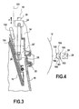
- a thermal protection screen 102 connected by a connection means 101 to the fixed downstream part of the fixed divergent section 12 is interposed between the fixed divergent section 12 and the divergent deployment mechanism 18 in order to protect the latter against the thermal radiation emitted by the divergent.
- the rigid heat shield 102 protects the lower portion of the divergent deployment mechanism 18.
- the heat shield 102 has a wall 104 convex on its side facing the section 12 of divergent fixed.
- the convexity of the screen 102 reduces its view factor relative to the section 12 of fixed divergent and thus allows the latter to radiate to the sidereal vacuum, so that through the screen 102 the overheating of the divergent is decreased.
- the convexity of the heat shield 102 also makes it possible to increase the rigidity of the latter with respect to a flat screen.
- Lateral wings 105, 106 are advantageously formed on the heat shield 102 on either side of the convex wall 104 in order to increase the exchange of calories by radiation to the sidereal vacuum and also to help stiffen the structure.
- the means 101 for connecting the thermal protection shield 102 to the fixed downstream part of the fixed divergent section 12 comprises a fastening strip which is connected by concave side ends 101a, 101b, forming connecting tabs, to the fins 105, 106 side of the heat shield 102, a slot 107 being formed between the convex wall 104 and the fastening strip 101.
- a strip 103 of flexible thermal protection is disposed between the rigid thermal protection screen 102 and the divergent deployment mechanism 18 (see FIG. figures 3 and 6 ).
- the band 103 of flexible thermal protection extends over the entire height of the fixed divergent section 12 while the rigid thermal protection screen 102 extends over the only lower part of the fixed divergent section 12.
- the band 103 of flexible thermal protection is thus disposed between each rod 20 and the section 12 of fixed divergent. It is not deployable, which facilitates its installation.
- the flexible thermal protection strip 103 allows the rods 20 to be light and to exchange calories to the space by radiation. Such a flexible thermal protection does not generate a thermomechanical load at the interfaces and its mass remains low.
- the rigid thermal protection screen 102 itself has a limited height so as not to increase the mass excessively while protecting the most sensitive lower part of the mechanism 18 of deployment of divergent.
- the convex wall 104 of the screen 102 may have a curved section or corresponding to a polygon portion.
- the temperature is reduced at the divergent deployment mechanism 18 and this mechanism is not likely to be damaged during operation.
- the thermal protection screen 102 may be made of a refractory metal material such as an alloy based on tungsten, molybdenum or tungsten and molybdenum and the flexible thermal protection strip 103 is made of borosilicate and fiber fabric. alumina.
Landscapes
- Engineering & Computer Science (AREA)
- Chemical & Material Sciences (AREA)
- Combustion & Propulsion (AREA)
- Mechanical Engineering (AREA)
- General Engineering & Computer Science (AREA)
- Toys (AREA)
- Thermal Insulation (AREA)
- Exhaust Silencers (AREA)
- Connection Of Plates (AREA)
Description
- La présente invention concerne un moteur fusée à divergent déployable, comprenant une tuyère d'échappement des gaz issus d'une chambre de combustion, ladite tuyère présentant un axe longitudinal et comprenant une première partie définissant un col de tuyère et un premier tronçon de divergent fixe, au moins un deuxième tronçon de divergent déployable de section supérieure à celle du premier tronçon de divergent fixe et un mécanisme de déploiement du deuxième tronçon de divergent déployable disposé à l'extérieur des premier et deuxième tronçons de divergent.
- On utilise fréquemment, notamment sur des étages de lanceurs, des tuyères de moteur-fusée à divergent déployable qui permettent d'adapter la section de sortie de la tuyère en fonction de la pression ambiante, laquelle diminue entre les faibles altitudes proches du sol et les altitudes élevées pour lesquelles le véhicule spatial quitte l'atmosphère terrestre, de telle sorte qu'une poussée optimale soit conservée malgré les changements d'altitude.
- Le déploiement de la partie déployable du divergent s'effectue de façon automatique à partir d'une commande électrique ou hydraulique, voire pneumatique.
- Des exemples de divergents déployables de tuyères de moteurs-fusées sont décrits notamment dans les documents
US 4 383 407 ,US 5 048 289 ,EP 0 516 519 B1 etUS 7 299 636 B2 . - Les divergents déployables de forme sensiblement conique peuvent être métalliques avec des circuits de refroidissement régénératifs ou en matériau composite.
- On connaît en particulier le moteur VINCI qui est un moteur-fusée à ergols cryotechniques à divergent déployable en matériau composite thermostructural et dispose d'un mécanisme de déploiement (MDD) composé d'une vis sans fin et d'un système de fixation d'une part sur la partie conique supérieure fixée à la structure de la chambre de combustion et d'autre part à la partie conique inférieure mobile du divergent.
- Le mécanisme de déploiement est situé en vis-à-vis du divergent qui, en fonctionnement du moteur-fusée, émet par rayonnement thermique un flux pouvant atteindre, à certains endroits, 250 kW par m2 de divergent.
- Ce fort flux thermique incident provoque une augmentation globale de la température des éléments constituant le mécanisme de déploiement, ce qui contribue à faire baisser leurs propriétés mécaniques et, dans certains cas peut même affecter l'intégrité de ces éléments et conduire à une destruction de certains de ces éléments.
- L'invention vise à remédier aux inconvénients précités et à augmenter la fiabilité d'un moteur-fusée à divergent déployable en minimisant les effets du rayonnement thermique émis par le divergent lors du fonctionnement du moteur-fusée.
- Ces buts sont atteints, conformément à l'invention, grâce à un moteur-fusée à divergent déployable, comprenant une tuyère d'échappement des gaz issus d'une chambre de combustion, ladite tuyère présentant un axe longitudinal comprenant une première partie définissant un col de tuyère et un premier tronçon de divergent fixe, au moins un deuxième tronçon de divergent déployable de section supérieure à celle du premier tronçon de divergent fixe et un mécanisme de déploiement du deuxième tronçon de divergent déployable disposé à l'extérieur des premier et deuxième tronçons de divergent, caractérisé en ce qu'il comprend en outre un écran de protection thermique rigide interposé entre le mécanisme de déploiement et le premier tronçon de divergent fixe, et en ce que l'écran de protection thermique présente une paroi convexe sur sa face tournée vers le premier tronçon de divergent fixe.
- Avantageusement, l'écran de protection thermique comprend en outre des ailettes latérales de part et d'autre de ladite paroi convexe.
- De préférence, le moteur-fusée comprend en outre une bande de protection thermique souple disposée entre l'écran de protection thermique rigide et le mécanisme de déploiement.
- Avantageusement, la bande de protection thermique souple s'étend sur toute la hauteur du premier tronçon de divergent fixe tandis que l'écran de protection thermique rigide s'étend sur la seule partie inférieure du premier tronçon de divergent fixe.
- Avantageusement, l'écran de protection thermique rigide est réalisé en matériau métallique réfractaire tel qu'un alliage de tungstène et/ou de molybdène.
- Avantageusement, la bande de protection thermique souple est réalisée en toile de borosilicate et de fibres d'alumine.
- Selon un mode de réalisation particulier, le mécanisme de déploiement comprend une vis sans fin solidaire du premier tronçon de divergent fixe et un écrou à billes engagé dans la vis sans fin et solidaire de la partie supérieure du deuxième tronçon de divergent mobile.
- Avantageusement, l'écrou à billes est relié à la partie supérieure du deuxième tronçon de divergent mobile par une pièce en forme d'ailette.
- D'autres caractéristiques et avantages de l'invention ressortiront de la description suivante de modes particuliers de réalisation, donnés à titre d'exemples, en référence aux dessins annexés, sur lesquels :
- la
figure 1 est une vue de côté et partiellement en coupe longitudinale montrant un exemple de divergent déployable de moteur-fusée en position rétractée, auquel l'invention est applicable, - la
figure 2 est une vue de côté et partiellement en coupe longitudinale du divergent déployable de lafigure 1 en position déployée. - la
figure 3 est une vue de détail d'un exemple de mécanisme de déploiement de divergent équipé d'un exemple de système de protection thermique selon la présente invention, - la
figure 4 est une vue de dessus du système de protection thermique selon l'invention pris selon la flèche F de lafigure 3 , et - les
figures 5 et 6 sont des vues en perspective montrant des exemples d'écran utilisables dans le système de protection thermique selon l'invention. - On voit sur les
figures 1 et 2 un exemple de moteur-fusée comprenant une chambre de combustion 14 à laquelle est rattachée une tuyère 10 d'axe longitudinal ZZ' comprenant un col de tuyère 15 et un divergent déployable. - La tuyère 10 comprend une première partie fixée à la chambre de combustion 14 et définissant le col de tuyère 15 ainsi qu'un tronçon 12 de divergent fixe ayant une forme sensiblement tronconique et une deuxième partie constituée par un tronçon 16 de divergent déployable présentant une forme sensiblement tronconique avec une section supérieure à celle du tronçon 12 de divergent fixe.
- Un mécanisme 18 de déploiement de divergent (MDD) permet de modifier de façon sélective la position du tronçon 16 de divergent déployable par rapport à celle du tronçon 12 de divergent fixe.
- On voit sur la
figure 1 , le tronçon 16 de divergent déployable placé en position rétractée autour du tronçon 12 de divergent fixe et de la chambre de combustion 14. Cette position rétractée peut correspondre à une phase de transport pour un moteur-fusée d'étage supérieur d'un lanceur. Cette position rétractée peut aussi correspondre à une première phase de fonctionnement dans laquelle les gaz de combustion s'échappent à travers le seul tronçon 12 de divergent fixe. - La
figure 2 montre le tronçon 16 de divergent déployable en position déployée dans laquelle ce tronçon 16 de divergent prolonge vers l'aval le tronçon 12 de divergent fixe de manière à créer un divergent de plus grande longueur et de plus grand diamètre de sortie. - Le mécanisme 18 de déploiement du divergent peut être réalisé de diverses manières avec par exemple des bras de levier ou des tiges de guidage.
- Selon l'exemple représenté sur les
figures 1 à 4 , le mécanisme 18 de déploiement de divergent comprend plusieurs (par exemple trois à six) tiges 20 parallèles à l'axe ZZ' qui incluent chacune une vis sans fin 26 coopérant avec un écrou à billes 22. Chaque tige 20 est fixée à sa partie inférieure à un bloc de fixation 25 qui est monté à la partie aval du tronçon 12 de divergent fixe. Les tiges 20 présentent des extrémités supérieures solidaires de la structure de support du moteur-fusée, non représentée sur les dessins. L'écrou à billes 22 coopérant avec la vis sans fin 26 d'une tige de guidage 20 est lui-même raccordé à la partie supérieure du tronçon 16 de divergent déployable. L'élément de raccord entre l'écrou à billes 22 et le tronçon 16 de divergent déployable peut comprendre une plaque 34 en forme d'ailette capable d'évacuer la chaleur reçue et une pince 35 se fixant à la partie supérieure du tronçon 16 de divergent déployable. - Dans la position rétractée du tronçon 16 de divergent déployable, représentée sur la
figure 1 , les écrous à billes 22 du mécanisme de déploiement 18 et les plaques de fixation 34 sont situés en position haute des tiges 20. - Dans la position déployée du tronçon 16 de divergent déployable, représentée sur la
figure 2 , les écrous à billes 22 (repérés dans cette position par la référence 22' sur lesfigures 2 et3 ) et les plaques de fixation 34 sont situés au voisinage de la jonction entre le tronçon 2 de divergent fixe et le tronçon 16 de divergent déployable. - La paroi du tronçon 12 de divergent fixe peut être en métal et dans ce dernier cas, il est avantageux que cette paroi soit refroidie par un circuit de refroidissement régénératif. La paroi du tronçon 12 de divergent fixe comme la paroi du tronçon 16 de divergent déployable, peuvent aussi avantageusement être en matériau composite, par exemple à matrice céramique.
- Lors du fonctionnement du moteur-fusée en position déployée du tronçon 16 de divergent déployable, le divergent et en particulier le tronçon 12 de divergent fixe émet par rayonnement thermique un flux pouvant atteindre, à certains endroits 250 kW par m2 de divergent, le divergent atteignant lui-même des températures pouvant excéder 1400 K.
- Conformément à l'invention, un écran de protection thermique 102 relié par un moyen de liaison 101 à la partie aval fixe du tronçon 12 de divergent fixe est interposé entre le tronçon 12 de divergent fixe et le mécanisme 18 de déploiement de divergent afin de protéger ce dernier contre le rayonnement thermique émis par le divergent.
- L'écran thermique 102 rigide protège la partie basse du mécanisme 18 de déploiement de divergent.
- Comme on peut le voir sur les
figures 3 à 5 , l'écran thermique 102 présente une paroi 104 convexe sur sa face tournée vers le tronçon 12 de divergent fixe. - La convexité de l'écran 102 permet de réduire son facteur de vue par rapport au tronçon 12 de divergent fixe et permet ainsi à ce dernier de rayonner vers le vide sidéral, de telle sorte que grâce à l'écran 102 la surchauffe du divergent est diminuée.
- La convexité de l'écran thermique 102 permet également d'augmenter la rigidité de celui-ci par rapport à un écran plat.
- Des ailettes latérales 105, 106 sont avantageusement formées sur l'écran thermique 102 de part et d'autre de la paroi convexe 104 afin d'augmenter l'échange de calories par rayonnement vers le vide sidéral et également de contribuer à rigidifier la structure.
- Dans l'exemple de la
figure 5 , le moyen 101 de liaison de l'écran de protection thermique 102 à la partie aval fixe du tronçon 12 de divergent fixe comprend une bande de fixation qui est reliée par des extrémités latérales 101a, 101b recourbées, formant des pattes de liaison, aux ailettes latérales 105, 106 de l'écran thermique 102, une fente 107 étant ménagée entre la paroi convexe 104 et la bande de fixation 101. - Avantageusement, une bande 103 de protection thermique souple est disposée entre l'écran 102 de protection thermique rigide et le mécanisme 18 de déploiement de divergent (voir les
figures 3 et6 ). - La bande 103 de protection thermique souple s'étend sur toute la hauteur du tronçon 12 de divergent fixe tandis que l'écran 102 rigide de protection thermique s'étend sur la seule partie inférieure du tronçon 12 de divergent fixe.
- La bande 103 de protection thermique souple est ainsi disposée entre chaque tige 20 et le tronçon 12 de divergent fixe. Elle n'est pas déployable, ce qui facilite son installation. La bande 103 de protection thermique souple permet aux tiges 20 d'être légères et d'échanger des calories vers l'espace par rayonnement. Une telle protection thermique souple ne génère pas de charge thermomécanique aux interfaces et sa masse reste faible.
- L'écran de protection thermique rigide 102 présente lui-même une hauteur limitée pour ne pas augmenter la masse de façon excessive tout en protégeant la partie inférieure la plus sensible du mécanisme 18 de déploiement de divergent. La paroi 104 convexe de l'écran 102 peut présenter une section courbe ou correspondant à une portion de polygone.
- Grâce à l'écran thermique rigide 102 et à la bande 103 de protection thermique souple, la température est réduite au niveau du mécanisme 18 de déploiement de divergent et ce mécanisme ne risque pas d'être endommagé en cours de fonctionnement.
- Avantageusement, l'écran 102 de protection thermique peut être réalisé en un matériau métallique réfractaire comme un alliage à base de tungstène, de molybdène ou de tungstène et de molybdène et la bande 103 de protection thermique souple est réalisée en toile de borosilicate et de fibre d'alumine.
Claims (10)
- Moteur-fusée à divergent déployable, comprenant une tuyère (10) d'échappement des gaz issus d'une chambre de combustion (14), ladite tuyère (10) présentant un axe longitudinal (ZZ') comprenant une première partie définissant un col de tuyère (15) et un premier tronçon (12) de divergent fixe, au moins un deuxième tronçon (16) de divergent déployable de section supérieure à celle du premier tronçon (12) de divergent fixe et un mécanisme (18) de déploiement du deuxième tronçon (16) de divergent déployable disposé à l'extérieur des premier et deuxième tronçons (12, 16) de divergent,
caractérisé en ce qu'il comprend en outre un écran (102) de protection thermique rigide interposé entre le mécanisme de déploiement (18) et le premier tronçon (12) de divergent fixe,et en ce que l'écran de protection thermique (102) présente une paroi convexe (104) sur sa face tournée vers le premier tronçon (12) de divergent fixe. - Moteur-fusée selon la revendication 1, caractérisé en ce que l'écran de protection thermique comprend en outre des ailettes latérales (105, 106) de part et d'autre de ladite paroi convexe (104).
- Moteur-fusée selon la revendication 2, caractérisé en ce qu'il comprend en outre une bande (103) de protection thermique souple disposée entre l'écran de protection thermique rigide (102) et le mécanisme (18) de déploiement.
- Moteur-fusée selon la revendication 3, caractérisé en ce que la bande (103) de protection thermique souple s'étend sur toute la hauteur du premier tronçon (12) de divergent fixe tandis que l'écran (102) de protection thermique rigide s'étend sur la seule partie inférieure du premier tronçon (12) de divergent fixe.
- Moteur-fusée selon l'une quelconque des revendications 1 à 4, caractérisé en ce que l'écran (102) de protection thermique rigide est réalisé en un matériau métallique réfractaire.
- Moteur-fusée selon la revendication 5, caractérisé en ce que l'écran (102) de protection thermique rigide est réalisé en alliage de tungstène, en alliage de molybdène ou en alliage de tungstène et de molybdène.
- Moteur-fusée selon l'une des revendications 3 et 4, caractérisé en ce que la bande (103) de protection thermique souple est en toile de borosilicate et de fibres d'alumine.
- Moteur-fusée selon l'une quelconque des revendications 1 à 7, caractérisé en ce que le mécanisme de déploiement (18) comprend une vis sans fin (26) solidaire du premier tronçon (12) de divergent fixe et un écrou à billes (22) engagé dans la vis sans fin (26) et solidaire de la partie supérieure du deuxième tronçon (16) de divergent mobile.
- Moteur-fusée selon la revendication 8, caractérisé en ce que l'écrou à billes (22) est relié à la partie supérieure du deuxième tronçon (16) de divergent mobile par une pièce (34) en forme d'ailette.
- Moteur-fusée selon la revendication 2, caractérisé en ce que les ailettes latérales (105, 106) de l'écran de protection thermique (102) sont reliées à des pattes (101a, 101b) solidaires d'une bande (101) de fixation sur la partie aval du premier tronçon (12) de divergent fixe.
Applications Claiming Priority (2)
| Application Number | Priority Date | Filing Date | Title |
|---|---|---|---|
| FR0956178A FR2949821B1 (fr) | 2009-09-10 | 2009-09-10 | Moteur fusee a divergent deployable |
| PCT/FR2010/051844 WO2011030048A1 (fr) | 2009-09-10 | 2010-09-06 | Moteur fusee a divergent deployable. |
Publications (2)
| Publication Number | Publication Date |
|---|---|
| EP2475866A1 EP2475866A1 (fr) | 2012-07-18 |
| EP2475866B1 true EP2475866B1 (fr) | 2013-07-10 |
Family
ID=41509017
Family Applications (1)
| Application Number | Title | Priority Date | Filing Date |
|---|---|---|---|
| EP10763814.0A Active EP2475866B1 (fr) | 2009-09-10 | 2010-09-06 | Moteur fusee a divergent deployable. |
Country Status (7)
| Country | Link |
|---|---|
| US (1) | US9169807B2 (fr) |
| EP (1) | EP2475866B1 (fr) |
| JP (1) | JP5636056B2 (fr) |
| CN (1) | CN102639853A (fr) |
| FR (1) | FR2949821B1 (fr) |
| RU (1) | RU2531009C2 (fr) |
| WO (1) | WO2011030048A1 (fr) |
Families Citing this family (13)
| Publication number | Priority date | Publication date | Assignee | Title |
|---|---|---|---|---|
| FR2956739B1 (fr) * | 2010-02-24 | 2012-09-14 | Snecma | Banc d'essai pour moteur a reaction |
| FR2989354B1 (fr) * | 2012-04-13 | 2014-05-23 | Snecma | Etage de lanceur comprenant une structure de support temporaire de troncons de tuyere, permettant l'acces au corps du moteur |
| FR2998022B1 (fr) | 2012-11-15 | 2015-01-16 | Snecma | Tige filetee d'un systeme de deploiement d'un divergent deployable de propulseur |
| CN105179109B (zh) * | 2015-06-08 | 2017-05-17 | 北京航天动力研究所 | 一种采用气吹原理的喷管延伸展开机构 |
| CN105067232B (zh) * | 2015-07-14 | 2017-09-29 | 北京航天动力研究所 | 利用滑轮和重锤实现延伸机构功能和载荷试验的装置 |
| RU2595006C1 (ru) * | 2015-09-02 | 2016-08-20 | Акционерное общество "Конструкторское бюро химавтоматики" | Жидкостный ракетный двигатель с выдвижным соплом |
| RU167750U1 (ru) * | 2016-03-15 | 2017-01-10 | Федеральное государственное бюджетное образовательное учреждение высшего образования Московский авиационный институт (национальный исследовательский университет) (МАИ) | Высотное сопло лаваля |
| RU2612691C1 (ru) * | 2016-03-31 | 2017-03-13 | Акционерное общество "Конструкторское бюро химавтоматики" | Жидкостный ракетный двигатель с выдвижным соплом |
| FR3060663B1 (fr) * | 2016-12-19 | 2019-05-24 | Airbus Safran Launchers Sas | Dispositif de protection thermique souple pour divergent |
| AU2018346994B2 (en) | 2017-10-13 | 2022-12-22 | The Commonwealth Of Australia | Rigid thermal protection composition |
| US11352981B1 (en) * | 2019-08-02 | 2022-06-07 | Exquadrum, Inc. | Multi-pulse rocket propulsion motor |
| CN117529435A (zh) * | 2021-04-13 | 2024-02-06 | 斯托克太空科技公司 | 非轴对称隔热罩、至少部分由隔热罩限定的喷管、包括喷管的发动机和包括发动机的运载工具 |
| WO2024019721A1 (fr) * | 2022-07-21 | 2024-01-25 | Alpha Portfolio LLC | Systèmes de moteur et leurs utilisations |
Family Cites Families (23)
| Publication number | Priority date | Publication date | Assignee | Title |
|---|---|---|---|---|
| US1559727A (en) | 1919-10-09 | 1925-11-03 | Merseles | Dishwashing machine |
| US3156091A (en) * | 1961-07-19 | 1964-11-10 | Curtiss Wright Corp | Multi-layer anisotropic heat shield construction |
| US3215373A (en) * | 1963-01-04 | 1965-11-02 | Hollas K Price | Rocket propulsion means for space craft |
| US3346186A (en) * | 1964-10-05 | 1967-10-10 | North American Aviation Inc | Extensible rocket nozzle comprised of a coated flexible mesh subsequently deployed and heated to become impermeable |
| US3933310A (en) * | 1974-07-11 | 1976-01-20 | Thiokol Corporation | Rocket nozzle construction and surfaces impervious to hot, high velocity gases |
| US4213566A (en) * | 1978-08-25 | 1980-07-22 | Hercules Incorporated | Nested cone extendible nozzle system for a rocket motor |
| US4313567A (en) * | 1979-12-03 | 1982-02-02 | Rockwell International Corporation | Cam-lock rocket securing mechanism |
| US4387564A (en) * | 1980-10-03 | 1983-06-14 | Textron Inc. | Extendible rocket engine exhaust nozzle assembly |
| US4383407A (en) * | 1981-02-02 | 1983-05-17 | Thiokol Corporation | Extendible thrust nozzle for rockets |
| DE3427169C2 (de) * | 1984-07-24 | 1987-04-30 | Messerschmitt-Bölkow-Blohm GmbH, 8012 Ottobrunn | Raketentriebwerk für Raumflüge |
| US4779799A (en) * | 1987-03-16 | 1988-10-25 | Rockwell International Corporation | Extendible nozzle |
| JPH0544508Y2 (fr) * | 1988-08-09 | 1993-11-11 | ||
| US5048289A (en) * | 1989-06-15 | 1991-09-17 | Rockwell International Corporation | Extendible nozzle |
| US5232534A (en) * | 1989-09-19 | 1993-08-03 | Aerospatiale Soiete Nationale Industrielle | Thermal protection coating, and method and installation for manufacturing it |
| FR2677080B1 (fr) * | 1991-05-30 | 1995-01-06 | Europ Propulsion | Mecanisme autoverrouillable et reversible de deploiement de divergent de tuyere de moteur-fusee. |
| JP3064673B2 (ja) * | 1992-05-30 | 2000-07-12 | スズキ株式会社 | 車両用排気マニホルドカバー |
| US5954491A (en) * | 1997-04-07 | 1999-09-21 | Eastman Chemical Company | Wire lock shield face for burner nozzle |
| DE10157752B4 (de) * | 2001-11-27 | 2006-04-06 | Eads Space Transportation Gmbh | Düsenverlängerung |
| DE10312776B4 (de) * | 2003-03-21 | 2008-10-02 | Eads Space Transportation Gmbh | Ausfahrbare Schubdüsenglocke für ein Raketentriebwerk |
| JP4278089B2 (ja) * | 2003-03-31 | 2009-06-10 | 株式会社泉精器製作所 | 生ゴミ処理装置および生ゴミ処理用カッタ |
| EP1482246A1 (fr) * | 2003-05-30 | 2004-12-01 | Siemens Aktiengesellschaft | Chambre de combustion |
| RU2273752C2 (ru) * | 2003-11-05 | 2006-04-10 | ОАО "НПО Энергомаш имени академика В.П. Глушко" | Сопло с высотной компенсацией |
| RU2272928C2 (ru) * | 2004-05-20 | 2006-03-27 | Открытое акционерное общество Научно-производственное объединение "Искра" | Раздвижное сопло ракетного двигателя |
-
2009
- 2009-09-10 FR FR0956178A patent/FR2949821B1/fr not_active Expired - Fee Related
-
2010
- 2010-09-06 JP JP2012528418A patent/JP5636056B2/ja not_active Expired - Fee Related
- 2010-09-06 US US13/395,344 patent/US9169807B2/en not_active Expired - Fee Related
- 2010-09-06 EP EP10763814.0A patent/EP2475866B1/fr active Active
- 2010-09-06 RU RU2012112417/06A patent/RU2531009C2/ru not_active IP Right Cessation
- 2010-09-06 CN CN2010800406778A patent/CN102639853A/zh active Pending
- 2010-09-06 WO PCT/FR2010/051844 patent/WO2011030048A1/fr not_active Ceased
Also Published As
| Publication number | Publication date |
|---|---|
| EP2475866A1 (fr) | 2012-07-18 |
| FR2949821B1 (fr) | 2011-09-30 |
| RU2531009C2 (ru) | 2014-10-20 |
| FR2949821A1 (fr) | 2011-03-11 |
| CN102639853A (zh) | 2012-08-15 |
| JP5636056B2 (ja) | 2014-12-03 |
| WO2011030048A1 (fr) | 2011-03-17 |
| US20120167575A1 (en) | 2012-07-05 |
| US9169807B2 (en) | 2015-10-27 |
| RU2012112417A (ru) | 2013-10-20 |
| JP2013504708A (ja) | 2013-02-07 |
Similar Documents
| Publication | Publication Date | Title |
|---|---|---|
| WO2011030048A1 (fr) | Moteur fusee a divergent deployable. | |
| FR2981636A1 (fr) | Carenage aerodynamique arriere pour dispositif d'accrochage d'un moteur d'aeronef, comprenant un bouclier thermique capable de se dilater librement | |
| CA2576100C (fr) | Mat d'accrochage de turboreacteur pour aeronef | |
| EP1883578B1 (fr) | Ensemble moteur pour aéronef | |
| EP2244944B1 (fr) | Ensemble moteur pour aeronef comprenant des attaches moteur deportees vers le bas sur le carter de soufflante | |
| EP2543864B1 (fr) | Ensemble propulsif avec un plancher de protection thermique d'un carenage aérodynamique arrière d'un mat d'accrochage et procéde de refroidissement du plancher de protection thermique | |
| EP2190739B1 (fr) | Carenage aerodynamique arriere inferieur pour dispositif d'accrochage d'un moteur d'aeronef | |
| EP0921293B1 (fr) | Dispositif d'évacuation d'air chaud pour capot d'entrée d'air de moteur à réaction à circuit de dégivrage | |
| EP1888894B1 (fr) | Capot d'entrée d'air pour turbomoteur avec système pour le dégivrage de son bord d'attaque | |
| EP2640639B1 (fr) | Structure de renforcement d'une nacelle de turboréacteur | |
| FR2802573A1 (fr) | Dispositif d'evacuation d'air chaud pour capot d'entree d'air de moteur a reaction, a circuit de degivrage | |
| FR2757571A1 (fr) | Divergent deployable pour propulseur | |
| FR2873987A1 (fr) | Ensemble moteur pour aeronef | |
| EP1873061B1 (fr) | Structure déployable comportant des éléments rigides, embarquée sur un engin spatial | |
| FR2905930A1 (fr) | Generateur de tourbillon en sortie de gaz chauds | |
| FR2887294A1 (fr) | Systeme pour le degivrage du bord d'attaque d'un capot d'entree d'air pour turbomoteur | |
| WO2012049399A1 (fr) | Ensemble d'accrochage d'une suspension d'un ensemble propulsif d'aéronef | |
| FR2835288A1 (fr) | Systeme de refroidissement pour une tuyere de post-combustion de turbomachine | |
| EP3396300A1 (fr) | Dispositif d'actionnement pour l'éjection d'au moins une partie amovible de missile, en particulier d'une coiffe | |
| EP1883580B1 (fr) | Ensemble moteur pour aeronef | |
| EP2855876B1 (fr) | Procede de montage ameliore d'un verin de commande d'une vanne de decharge d'air d'une turbomachine | |
| FR2909973A1 (fr) | Mat d'accrochage de turboreacteur pour aeronef a structure arriere de largeur transversale reduite | |
| FR2983172A1 (fr) | Carenage arriere pour mat d'accrochage d'un moteur | |
| EP3617490A1 (fr) | Écope de prélévement d'air pour aéronef | |
| EP4136357B1 (fr) | Dispositif de maintien et de libération à bas choc et réutilisable |
Legal Events
| Date | Code | Title | Description |
|---|---|---|---|
| PUAI | Public reference made under article 153(3) epc to a published international application that has entered the european phase |
Free format text: ORIGINAL CODE: 0009012 |
|
| 17P | Request for examination filed |
Effective date: 20120315 |
|
| AK | Designated contracting states |
Kind code of ref document: A1 Designated state(s): AL AT BE BG CH CY CZ DE DK EE ES FI FR GB GR HR HU IE IS IT LI LT LU LV MC MK MT NL NO PL PT RO SE SI SK SM TR |
|
| DAX | Request for extension of the european patent (deleted) | ||
| GRAP | Despatch of communication of intention to grant a patent |
Free format text: ORIGINAL CODE: EPIDOSNIGR1 |
|
| RIN1 | Information on inventor provided before grant (corrected) |
Inventor name: DAVID, NOEL Inventor name: RAVIER, NICOLAS Inventor name: DOBEK, OLIVIER |
|
| GRAS | Grant fee paid |
Free format text: ORIGINAL CODE: EPIDOSNIGR3 |
|
| GRAA | (expected) grant |
Free format text: ORIGINAL CODE: 0009210 |
|
| AK | Designated contracting states |
Kind code of ref document: B1 Designated state(s): AL AT BE BG CH CY CZ DE DK EE ES FI FR GB GR HR HU IE IS IT LI LT LU LV MC MK MT NL NO PL PT RO SE SI SK SM TR |
|
| REG | Reference to a national code |
Ref country code: GB Ref legal event code: FG4D Free format text: NOT ENGLISH |
|
| REG | Reference to a national code |
Ref country code: CH Ref legal event code: EP Ref country code: AT Ref legal event code: REF Ref document number: 621120 Country of ref document: AT Kind code of ref document: T Effective date: 20130715 |
|
| REG | Reference to a national code |
Ref country code: IE Ref legal event code: FG4D Free format text: LANGUAGE OF EP DOCUMENT: FRENCH |
|
| REG | Reference to a national code |
Ref country code: DE Ref legal event code: R096 Ref document number: 602010008498 Country of ref document: DE Effective date: 20130905 |
|
| REG | Reference to a national code |
Ref country code: SE Ref legal event code: TRGR |
|
| PG25 | Lapsed in a contracting state [announced via postgrant information from national office to epo] |
Ref country code: SI Free format text: LAPSE BECAUSE OF FAILURE TO SUBMIT A TRANSLATION OF THE DESCRIPTION OR TO PAY THE FEE WITHIN THE PRESCRIBED TIME-LIMIT Effective date: 20130710 |
|
| REG | Reference to a national code |
Ref country code: AT Ref legal event code: MK05 Ref document number: 621120 Country of ref document: AT Kind code of ref document: T Effective date: 20130710 |
|
| REG | Reference to a national code |
Ref country code: NL Ref legal event code: VDEP Effective date: 20130710 |
|
| REG | Reference to a national code |
Ref country code: LT Ref legal event code: MG4D |
|
| PG25 | Lapsed in a contracting state [announced via postgrant information from national office to epo] |
Ref country code: AT Free format text: LAPSE BECAUSE OF FAILURE TO SUBMIT A TRANSLATION OF THE DESCRIPTION OR TO PAY THE FEE WITHIN THE PRESCRIBED TIME-LIMIT Effective date: 20130710 Ref country code: LT Free format text: LAPSE BECAUSE OF FAILURE TO SUBMIT A TRANSLATION OF THE DESCRIPTION OR TO PAY THE FEE WITHIN THE PRESCRIBED TIME-LIMIT Effective date: 20130710 Ref country code: IS Free format text: LAPSE BECAUSE OF FAILURE TO SUBMIT A TRANSLATION OF THE DESCRIPTION OR TO PAY THE FEE WITHIN THE PRESCRIBED TIME-LIMIT Effective date: 20131110 Ref country code: NO Free format text: LAPSE BECAUSE OF FAILURE TO SUBMIT A TRANSLATION OF THE DESCRIPTION OR TO PAY THE FEE WITHIN THE PRESCRIBED TIME-LIMIT Effective date: 20131010 Ref country code: PT Free format text: LAPSE BECAUSE OF FAILURE TO SUBMIT A TRANSLATION OF THE DESCRIPTION OR TO PAY THE FEE WITHIN THE PRESCRIBED TIME-LIMIT Effective date: 20131111 Ref country code: HR Free format text: LAPSE BECAUSE OF FAILURE TO SUBMIT A TRANSLATION OF THE DESCRIPTION OR TO PAY THE FEE WITHIN THE PRESCRIBED TIME-LIMIT Effective date: 20130710 Ref country code: CY Free format text: LAPSE BECAUSE OF FAILURE TO SUBMIT A TRANSLATION OF THE DESCRIPTION OR TO PAY THE FEE WITHIN THE PRESCRIBED TIME-LIMIT Effective date: 20130904 |
|
| PG25 | Lapsed in a contracting state [announced via postgrant information from national office to epo] |
Ref country code: FI Free format text: LAPSE BECAUSE OF FAILURE TO SUBMIT A TRANSLATION OF THE DESCRIPTION OR TO PAY THE FEE WITHIN THE PRESCRIBED TIME-LIMIT Effective date: 20130710 Ref country code: GR Free format text: LAPSE BECAUSE OF FAILURE TO SUBMIT A TRANSLATION OF THE DESCRIPTION OR TO PAY THE FEE WITHIN THE PRESCRIBED TIME-LIMIT Effective date: 20131011 Ref country code: NL Free format text: LAPSE BECAUSE OF FAILURE TO SUBMIT A TRANSLATION OF THE DESCRIPTION OR TO PAY THE FEE WITHIN THE PRESCRIBED TIME-LIMIT Effective date: 20130710 Ref country code: LV Free format text: LAPSE BECAUSE OF FAILURE TO SUBMIT A TRANSLATION OF THE DESCRIPTION OR TO PAY THE FEE WITHIN THE PRESCRIBED TIME-LIMIT Effective date: 20130710 Ref country code: PL Free format text: LAPSE BECAUSE OF FAILURE TO SUBMIT A TRANSLATION OF THE DESCRIPTION OR TO PAY THE FEE WITHIN THE PRESCRIBED TIME-LIMIT Effective date: 20130710 Ref country code: ES Free format text: LAPSE BECAUSE OF FAILURE TO SUBMIT A TRANSLATION OF THE DESCRIPTION OR TO PAY THE FEE WITHIN THE PRESCRIBED TIME-LIMIT Effective date: 20131021 |
|
| BERE | Be: lapsed |
Owner name: SNECMA Effective date: 20130930 |
|
| PG25 | Lapsed in a contracting state [announced via postgrant information from national office to epo] |
Ref country code: CY Free format text: LAPSE BECAUSE OF FAILURE TO SUBMIT A TRANSLATION OF THE DESCRIPTION OR TO PAY THE FEE WITHIN THE PRESCRIBED TIME-LIMIT Effective date: 20130710 |
|
| PG25 | Lapsed in a contracting state [announced via postgrant information from national office to epo] |
Ref country code: DK Free format text: LAPSE BECAUSE OF FAILURE TO SUBMIT A TRANSLATION OF THE DESCRIPTION OR TO PAY THE FEE WITHIN THE PRESCRIBED TIME-LIMIT Effective date: 20130710 Ref country code: EE Free format text: LAPSE BECAUSE OF FAILURE TO SUBMIT A TRANSLATION OF THE DESCRIPTION OR TO PAY THE FEE WITHIN THE PRESCRIBED TIME-LIMIT Effective date: 20130710 Ref country code: SK Free format text: LAPSE BECAUSE OF FAILURE TO SUBMIT A TRANSLATION OF THE DESCRIPTION OR TO PAY THE FEE WITHIN THE PRESCRIBED TIME-LIMIT Effective date: 20130710 Ref country code: MC Free format text: LAPSE BECAUSE OF FAILURE TO SUBMIT A TRANSLATION OF THE DESCRIPTION OR TO PAY THE FEE WITHIN THE PRESCRIBED TIME-LIMIT Effective date: 20130710 Ref country code: CZ Free format text: LAPSE BECAUSE OF FAILURE TO SUBMIT A TRANSLATION OF THE DESCRIPTION OR TO PAY THE FEE WITHIN THE PRESCRIBED TIME-LIMIT Effective date: 20130710 Ref country code: RO Free format text: LAPSE BECAUSE OF FAILURE TO SUBMIT A TRANSLATION OF THE DESCRIPTION OR TO PAY THE FEE WITHIN THE PRESCRIBED TIME-LIMIT Effective date: 20130710 |
|
| PLBE | No opposition filed within time limit |
Free format text: ORIGINAL CODE: 0009261 |
|
| STAA | Information on the status of an ep patent application or granted ep patent |
Free format text: STATUS: NO OPPOSITION FILED WITHIN TIME LIMIT |
|
| 26N | No opposition filed |
Effective date: 20140411 |
|
| REG | Reference to a national code |
Ref country code: IE Ref legal event code: MM4A |
|
| REG | Reference to a national code |
Ref country code: DE Ref legal event code: R097 Ref document number: 602010008498 Country of ref document: DE Effective date: 20140411 |
|
| PG25 | Lapsed in a contracting state [announced via postgrant information from national office to epo] |
Ref country code: IE Free format text: LAPSE BECAUSE OF NON-PAYMENT OF DUE FEES Effective date: 20130906 Ref country code: BE Free format text: LAPSE BECAUSE OF NON-PAYMENT OF DUE FEES Effective date: 20130930 |
|
| REG | Reference to a national code |
Ref country code: CH Ref legal event code: PL |
|
| GBPC | Gb: european patent ceased through non-payment of renewal fee |
Effective date: 20140906 |
|
| PG25 | Lapsed in a contracting state [announced via postgrant information from national office to epo] |
Ref country code: SM Free format text: LAPSE BECAUSE OF FAILURE TO SUBMIT A TRANSLATION OF THE DESCRIPTION OR TO PAY THE FEE WITHIN THE PRESCRIBED TIME-LIMIT Effective date: 20130710 |
|
| PG25 | Lapsed in a contracting state [announced via postgrant information from national office to epo] |
Ref country code: TR Free format text: LAPSE BECAUSE OF FAILURE TO SUBMIT A TRANSLATION OF THE DESCRIPTION OR TO PAY THE FEE WITHIN THE PRESCRIBED TIME-LIMIT Effective date: 20130710 Ref country code: MT Free format text: LAPSE BECAUSE OF FAILURE TO SUBMIT A TRANSLATION OF THE DESCRIPTION OR TO PAY THE FEE WITHIN THE PRESCRIBED TIME-LIMIT Effective date: 20130710 |
|
| PG25 | Lapsed in a contracting state [announced via postgrant information from national office to epo] |
Ref country code: MK Free format text: LAPSE BECAUSE OF FAILURE TO SUBMIT A TRANSLATION OF THE DESCRIPTION OR TO PAY THE FEE WITHIN THE PRESCRIBED TIME-LIMIT Effective date: 20130710 Ref country code: BG Free format text: LAPSE BECAUSE OF FAILURE TO SUBMIT A TRANSLATION OF THE DESCRIPTION OR TO PAY THE FEE WITHIN THE PRESCRIBED TIME-LIMIT Effective date: 20130710 Ref country code: LI Free format text: LAPSE BECAUSE OF NON-PAYMENT OF DUE FEES Effective date: 20140930 Ref country code: GB Free format text: LAPSE BECAUSE OF NON-PAYMENT OF DUE FEES Effective date: 20140906 Ref country code: HU Free format text: LAPSE BECAUSE OF FAILURE TO SUBMIT A TRANSLATION OF THE DESCRIPTION OR TO PAY THE FEE WITHIN THE PRESCRIBED TIME-LIMIT; INVALID AB INITIO Effective date: 20100906 Ref country code: LU Free format text: LAPSE BECAUSE OF NON-PAYMENT OF DUE FEES Effective date: 20130906 Ref country code: CH Free format text: LAPSE BECAUSE OF NON-PAYMENT OF DUE FEES Effective date: 20140930 |
|
| REG | Reference to a national code |
Ref country code: FR Ref legal event code: PLFP Year of fee payment: 7 |
|
| REG | Reference to a national code |
Ref country code: FR Ref legal event code: PLFP Year of fee payment: 8 |
|
| REG | Reference to a national code |
Ref country code: DE Ref legal event code: R081 Ref document number: 602010008498 Country of ref document: DE Owner name: ARIANEGROUP SAS, FR Free format text: FORMER OWNER: SNECMA, PARIS, FR |
|
| REG | Reference to a national code |
Ref country code: DE Ref legal event code: R081 Ref document number: 602010008498 Country of ref document: DE Owner name: ARIANEGROUP SAS, FR Free format text: FORMER OWNER: AIRBUS SAFRAN LAUNCHERS SAS, ISSY-LES-MOULINEAUX, FR |
|
| REG | Reference to a national code |
Ref country code: FR Ref legal event code: PLFP Year of fee payment: 9 |
|
| PG25 | Lapsed in a contracting state [announced via postgrant information from national office to epo] |
Ref country code: AL Free format text: LAPSE BECAUSE OF FAILURE TO SUBMIT A TRANSLATION OF THE DESCRIPTION OR TO PAY THE FEE WITHIN THE PRESCRIBED TIME-LIMIT Effective date: 20130710 |
|
| PGFP | Annual fee paid to national office [announced via postgrant information from national office to epo] |
Ref country code: DE Payment date: 20180913 Year of fee payment: 9 |
|
| PGFP | Annual fee paid to national office [announced via postgrant information from national office to epo] |
Ref country code: SE Payment date: 20180917 Year of fee payment: 9 |
|
| REG | Reference to a national code |
Ref country code: DE Ref legal event code: R119 Ref document number: 602010008498 Country of ref document: DE |
|
| PG25 | Lapsed in a contracting state [announced via postgrant information from national office to epo] |
Ref country code: SE Free format text: LAPSE BECAUSE OF NON-PAYMENT OF DUE FEES Effective date: 20190907 |
|
| REG | Reference to a national code |
Ref country code: SE Ref legal event code: EUG |
|
| PG25 | Lapsed in a contracting state [announced via postgrant information from national office to epo] |
Ref country code: DE Free format text: LAPSE BECAUSE OF NON-PAYMENT OF DUE FEES Effective date: 20200401 |
|
| P01 | Opt-out of the competence of the unified patent court (upc) registered |
Effective date: 20230612 |
|
| PGFP | Annual fee paid to national office [announced via postgrant information from national office to epo] |
Ref country code: IT Payment date: 20250923 Year of fee payment: 16 |
|
| PGFP | Annual fee paid to national office [announced via postgrant information from national office to epo] |
Ref country code: FR Payment date: 20250922 Year of fee payment: 16 |