EP2475218A1 - Method and system for wireless access point radios integrated in a cable - Google Patents
Method and system for wireless access point radios integrated in a cable Download PDFInfo
- Publication number
- EP2475218A1 EP2475218A1 EP11009947A EP11009947A EP2475218A1 EP 2475218 A1 EP2475218 A1 EP 2475218A1 EP 11009947 A EP11009947 A EP 11009947A EP 11009947 A EP11009947 A EP 11009947A EP 2475218 A1 EP2475218 A1 EP 2475218A1
- Authority
- EP
- European Patent Office
- Prior art keywords
- wireless
- cable
- radio
- format
- data packet
- Prior art date
- Legal status (The legal status is an assumption and is not a legal conclusion. Google has not performed a legal analysis and makes no representation as to the accuracy of the status listed.)
- Granted
Links
- 238000000034 method Methods 0.000 title claims description 28
- 238000004891 communication Methods 0.000 claims abstract description 29
- 230000005540 biological transmission Effects 0.000 claims abstract description 15
- 230000002950 deficient Effects 0.000 claims description 12
- 238000012544 monitoring process Methods 0.000 claims description 2
- 238000010586 diagram Methods 0.000 description 6
- 238000004590 computer program Methods 0.000 description 4
- 230000001413 cellular effect Effects 0.000 description 3
- 230000035876 healing Effects 0.000 description 2
- 238000007726 management method Methods 0.000 description 2
- 239000000463 material Substances 0.000 description 2
- RYGMFSIKBFXOCR-UHFFFAOYSA-N Copper Chemical compound [Cu] RYGMFSIKBFXOCR-UHFFFAOYSA-N 0.000 description 1
- 238000013459 approach Methods 0.000 description 1
- 238000006243 chemical reaction Methods 0.000 description 1
- 229910052802 copper Inorganic materials 0.000 description 1
- 239000010949 copper Substances 0.000 description 1
- 238000013500 data storage Methods 0.000 description 1
- 238000001514 detection method Methods 0.000 description 1
- 238000005516 engineering process Methods 0.000 description 1
- 230000006870 function Effects 0.000 description 1
- 238000010348 incorporation Methods 0.000 description 1
- 230000010365 information processing Effects 0.000 description 1
- 230000002452 interceptive effect Effects 0.000 description 1
- 230000007246 mechanism Effects 0.000 description 1
- 238000012986 modification Methods 0.000 description 1
- 230000004048 modification Effects 0.000 description 1
- 230000006855 networking Effects 0.000 description 1
- 230000008569 process Effects 0.000 description 1
- 238000012545 processing Methods 0.000 description 1
- 238000001228 spectrum Methods 0.000 description 1
- 238000012546 transfer Methods 0.000 description 1
Images


Classifications
-
- H—ELECTRICITY
- H04—ELECTRIC COMMUNICATION TECHNIQUE
- H04W—WIRELESS COMMUNICATION NETWORKS
- H04W88/00—Devices specially adapted for wireless communication networks, e.g. terminals, base stations or access point devices
- H04W88/08—Access point devices
-
- H—ELECTRICITY
- H04—ELECTRIC COMMUNICATION TECHNIQUE
- H04L—TRANSMISSION OF DIGITAL INFORMATION, e.g. TELEGRAPHIC COMMUNICATION
- H04L12/00—Data switching networks
- H04L12/28—Data switching networks characterised by path configuration, e.g. LAN [Local Area Networks] or WAN [Wide Area Networks]
-
- H—ELECTRICITY
- H04—ELECTRIC COMMUNICATION TECHNIQUE
- H04L—TRANSMISSION OF DIGITAL INFORMATION, e.g. TELEGRAPHIC COMMUNICATION
- H04L12/00—Data switching networks
- H04L12/66—Arrangements for connecting between networks having differing types of switching systems, e.g. gateways
-
- H—ELECTRICITY
- H04—ELECTRIC COMMUNICATION TECHNIQUE
- H04W—WIRELESS COMMUNICATION NETWORKS
- H04W24/00—Supervisory, monitoring or testing arrangements
- H04W24/04—Arrangements for maintaining operational condition
Definitions
- Certain embodiments of the invention relate to communication systems. More specifically, certain embodiments of the invention relate to a method and system for wireless access point radios integrated in a cable.
- a wireless access point is a primary network access device of a wireless network such as a wireless local area network (LAN).
- the wireless AP enables one or more wireless communication devices to access the wireless LAN using exemplary wireless communication standards such as WiFi, Bluetooth, 60 GHz, ZigBee and/or picocell cellular.
- Wireless APs are operable to support one or more wireless communication standards for sending and receiving data utilizing radio frequencies (RF) rather than cabling.
- RF radio frequencies
- wireless APs may use standards defined by IEEE such as IEEE 802.11 standards.
- wireless APs may be communicatively coupled to a wired network such as a wired local area network (LAN), thereby providing wireless access to the wired network.
- a wireless AP may also be used in a home wireless network for connecting wireless enabled computers and/or other wireless communication devices in a home.
- the wireless AP may be integrated in a wireless router which may include the wireless AP, a router, an Ethernet switch and/or a broadband modem.
- the density of wireless APs may be high, and the same industrial, scientific and medical (ISM) spectrum may be shared by hundreds of wireless APs.
- ISM industrial, scientific and medical
- the actual coverage or range of the wireless AP may vary depending on such variables as indoor or outdoor environment, height above ground, nearby obstructions, interference from other active devices broadcasting on the same frequency, type of antenna, the current weather, operating radio frequency, and/or the power output of the wireless AP.
- a method for communication comprising:
- FIG. 1A is a block diagram illustrating an exemplary communication system that is operable to provide wireless access point radios integrated in a cable, in accordance with an embodiment of the invention.
- FIGS. 1B - 1C are block diagrams that each illustrates exemplary coverage of wireless access point radios integrated in a cable, in accordance with an embodiment of the invention.
- FIG. 2 is a block diagram illustrating an exemplary wireless access point radio integrated in a cable, in accordance with an embodiment of the invention.
- FIG. 3 is a flow chart illustrating exemplary steps for providing wireless access point radios integrated in a cable, in accordance with an embodiment of the invention.
- FIG. 4 is a flow chart illustrating exemplary steps for providing self healing utilizing wireless access point radios integrated in a cable, in accordance with an embodiment of the invention.
- a wireless access point (AP) radio may be integrated in a cable and the cable may comprise one or more other integrated wireless AP radios sharing the cable.
- the wireless AP radio may comprise one or more wireless transmitters and one or more wireless receivers.
- the cable may be communicatively coupled to a wireless controller and the wireless AP radio may be operable to receive power from the wireless controller via the cable.
- Feature information and/or configuration parameter settings may be received by the wireless AP radio from the wireless controller via the cable.
- the wireless AP radio may be operable to provide wireless access and/or wireless communication services for one or more client devices that are communicatively coupled to the wireless AP radio, based on the received feature information and/or the received configuration parameter settings.
- the wireless AP radio may provide access to a wired network for the one or more client devices.
- the wired network may be connected to the wireless controller.
- the wireless AP radio may receive a data packet having a wireless format from each of the one or more client devices, and transmit the data packet having the wireless format to the wireless controller via the cable.
- the wireless controller may convert the received data packet having the wireless format to generate a data packet having a wired format for transmitting to the wired network.
- the wireless AP radio may receive a data packet having a wireless format from the wireless controller via the cable, and transmit the data packet having the wireless format to each of the one or more client devices.
- the wireless controller may have converted a data packet having a wired format to generate the data packet having the wireless format after receiving the data packet in the wired format from the wired network.
- the wireless controller may identify the wireless AP radio integrated in the cable based on a media access control (MAC) address of the wireless AP radio. Upgraded feature information and/or updated configuration parameter settings may be received by the wireless AP radio from the wireless controller via the cable.
- the wireless AP radio may be operable to monitor and/or verify operations of one or more adjacent wireless AP radios integrated in the cable. In instances when one or more adjacent wireless AP radios integrated in the cable may become non-operational, the wireless AP radio may increase its transmission power to increase its coverage for covering at least a portion of coverage area associated with the one or more non-operational adjacent wireless AP radios.
- One or more new cables that each comprises one or more new wireless AP radios may be added to the cable so as to extend a total coverage area associated with the wireless AP radio and the one or more other wireless AP radios in the cable.
- a section of the cable comprising the wireless AP radio may be replaced by a new cable comprising one or more new wireless AP radios.
- FIG. 1A is a block diagram illustrating an exemplary communication system that is operable to provide wireless access point radios integrated in a cable, in accordance with an embodiment of the invention.
- a communication system 100 may comprise a wired network 101, a wireless controller 102, a plurality of cables, of which cables 104, 114 are illustrated, and a plurality of client devices, of which client devices 110a - 110c are illustrated.
- the client device 110a ⁇ 110c may be communicatively coupled to the wireless AP radio 104a.
- the cables 104, 114 may each comprise a plurality of integrated wireless AP radio, of which the wireless AP radios 104a ⁇ 104c and the wireless AP radios 114a ⁇ 114d are illustrated, respectively.
- Each of the wireless AP radios 104a - 104c, 114a - 114d may be placed apart at a short distance such as at 1 - 3 meters.
- the integrated wireless AP radios such as the wireless AP radios 104a ⁇ 104c may be a set of miniature wireless radios connected together by the cable 104.
- the wireless AP radios 104a - 104c may be connected together inside the cable 104.
- the wireless AP radios 104a ⁇ 104c may also be connected together by the cable 104 in a Christmas lights structure, for example.
- the wired network 101 may comprise suitable logic, circuitry, interfaces, communication devices and/or code that may be operable to provide communication and/or networking services to various devices such as the wireless controller 102 using wired technologies.
- the wired network 101 may be an Ethernet network which may communicate data packets with the wireless controller 102 using IEEE 802.3 standards.
- the wireless controller 102 may comprise suitable logic, circuitry, interfaces and/or code that may be operable to provide management and/or control functionalities to a plurality of wireless AP radios such as the wireless AP radios 104a - 104c, 114a - 114d, which are communicatively coupled to the wireless controller 102 via the cables 104, 114.
- the wireless controller 102 may be operable to discover or identify a wireless AP radio such as the wireless AP radio 104a connected to the wireless control 102 via the cable 104.
- the wireless controller 102 may identify the wireless AP radio 104a based on a MAC address of the wireless AP radio 104a, for example.
- the wireless controller 102 may provide power such as low voltage DC power to the wireless AP radio 104a via the cable 104.
- the wireless controller 102 may download feature information and/or configuration parameter settings to the wireless AP radio 104a, via the cable 104.
- the wireless AP radio 104a may then utilize the feature information and the configuration parameter settings to provide wireless access and/or wireless communication services to the client devices 110a ⁇ 110c.
- Each of the wireless AP radios such as the wireless AP radio 104a may comprise suitable logic, circuitry, interfaces and/or code that may be operable to provide wireless access and/or wireless communication services to one or more communicatively coupled client devices such as the client devices 110.
- the wireless AP radio 104a may comprise one or more wireless transmitters and one or more wireless receivers. A wireless transmitter and a wireless receiver may be integrated together as a transceiver, for example.
- the wireless AP radio 104a may be operable to provide, for the one or more client devices 110, wireless access to a wired network such as the wired network 101 which is connected to the wireless controller 102.
- the wireless AP radio 104a along with other wireless AP radios 104b - 104c are integrated in the cable 104.
- the cable 104 may be connected to the wireless controller 102 and the wireless controller 102 may be communicatively coupled to the wired network 101.
- the wireless AP radio 104a may receive power such as low voltage DC power from the wireless controller 102 via the cable 104.
- the low voltage DC power may be received using power over Ethernet (POE).
- POE power over Ethernet
- Feature information and/or configuration parameter settings may be downloaded to the wireless AP radio 104a from the wireless controller 102 via the cable 104.
- the wireless AP radio 104a may be operable to provide wireless access and/or wireless communication services for one or more client devices 110 that are communicatively coupled to the wireless AP radio 104a, based on the received feature information and/or the received configuration parameter settings.
- the wireless AP radio 104a may provide the wireless access and/or wireless communication services using IEEE 802.11 standards, for example.
- the received feature information may comprise, for example, software and/or firmware that may implement features based on the IEEE 802.11 standards.
- the feature information in addition to implementing features based on the IEEE 802.11 standards, the feature information may also comprise enterprise level features such as, for example, security, quality of service and/or other enterprise level management features.
- the configuration parameter settings may comprise, for example, power level setting, channel setting, security setting and/or other configurable parameter settings.
- the wireless AP radio 104a may provide access to the wired network 101 for the one or more client devices 110.
- the wired network 101 may be connected to the wireless controller 102.
- data packets that are travelling in the cable 104 are the same data packets that are travelling wirelessly over the air.
- the wireless AP radio 104 may receive a data packet having a wireless format from each of the one or more client devices 110 such as the client device 110a, and transmit the data packet having the wireless format to the wireless controller 102 via the cable 104.
- the wireless controller 102 may convert the received data packet having the wireless format to generate a data packet having a wired format for transmitting to the wired network 101.
- the data packet having a wireless format may comprise, for example, a data packet in the 802.11 format.
- the data packet having a wired format may comprise, for example, a data packet in the 802.3 format.
- the wired network 101 may transmit a data packet having a wired format such as the 802.3 format to the wireless controller 102.
- the wireless controller 102 may convert the received data packet having the wired format to generate a data packet having a wireless format such as the 802.11 format.
- the wireless controller 102 may transmit the data packet having the wireless format such as the 802.11 format to the wireless AP radio 104a via the cable 104.
- the wireless AP radio 104a may then transmit the received data packet having the wireless format to a communicatively coupled client device such as the client device 110a.
- the wireless controller 102 may hold on to the data packet and not transmit the data packet to the wireless AP radio 104a until the client device 110a is back to an active mode, for example.
- the wireless controller 102 may discover or identify the wireless AP radio 104a integrated in the cable 104 based on a unique MAC address of the wireless AP radio 104a. Upgraded feature information and/or updated configuration parameter settings may also be received by the wireless AP radio 104a from the wireless controller 102 via the cable 104.
- the wireless AP radio 104a may be operable to monitor and/or verify operations of one or more adjacent wireless AP radios such as the wireless AP radio 104b integrated in the cable 104.
- the wireless AP radio 104a may be instructed by the wireless controller 102 to increase its transmission power to increase its coverage for covering at least a portion of coverage area associated with the one or more non-operational adjacent wireless AP radios such as the wireless AP radio 104b.
- the wireless AP radio 104a may increase its transmission power based on a new or updated power level setting received from the wireless controller 102.
- One or more new cables that each comprises one or more new wireless AP radios may be added to the cable 104 so as to extend a total coverage area associated with the wireless AP radios 104a - 104c in the cable 104.
- a new cable such as the new cable 106, which may comprise new wireless AP radios 106a - 106b, may be added or connected to the cable 104, using splicing, for extending the total coverage area.
- a section of the cable 104 comprising the wireless AP radio 104a may be replaced by a new cable comprising one or more new wireless AP radios.
- a section 104s of the cable 104 may be replaced by a new cable such as the new cable 108 which may comprise a new wireless AP radio 108a.
- the wireless AP radio 104a provides wireless access for the client devices 110 to the wired network 101 via the cable 104.
- the invention is not so limited and other wireless communication services may be provided by the wireless AP radio 104a.
- the wireless AP radio 104a along with the other wireless AP radios 104b - 104c, 114a - 114d may form a mesh network, and a data packet received from the client device 110a may travel via the mesh network over the air until the data packet reaches a destination. Due to the relatively short range coverage provided by the wireless AP radio 104a, the wireless AP radio 104a may be able to provide an accurate location such as an indoor location to the client device 110a for location based services (LBS) applications, for example.
- LBS location based services
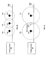
- FIGS. 1B ⁇ 1C are block diagrams that each illustrates exemplary coverage of wireless access point radios integrated in a cable, in accordance with an embodiment of the invention. These scenarios are provided by way of exemplary illustration and not of limitation. Referring to each of FIGS. 1B ⁇ 1C, there is shown the wireless controller 102, the cable 104 and the wireless AP radios 104a - 104c described above with respect to FIG. 1A . Each of the wireless AP radio 104a, 104b, 104c may be placed apart at a short distance such as, for example, at 1 - 3 meters, in the cable 104.
- FIG. 1B illustrates a first exemplary scenario in which all the wireless AP radios 104a, 104b, 104c are operational.
- each of the wireless AP radios 104a, 104b, 104c may be operable to provide normal coverage without interfering with neighbors, as illustrated by coverage 116a, coverage 116b and coverage 116c.
- Each of the wireless AP radios 104a, 104b, 104c may provide the normal coverage based on a power level setting received or downloaded from the wireless controller 102 via the cable 104.
- the wireless AP radio 104a may monitor and/or verify the operation of the wireless AP radio 104b.
- the wireless AP radio 104b may monitor and/or verify the operations of the wireless AP radios 104a, 104c.
- the wireless AP radio 104c may monitor and/or verify the operation of the wireless AP radio 104b.
- FIG. 1C illustrates a second exemplary scenario in which the wireless AP radios 104a, 104c are operational while the wireless AP radio 104b is detected to be non-operational or defective.
- each of the wireless AP radios 104a, 104c may receive an updated power level setting from the wireless controller 102.
- the wireless AP radio 104a may increase its transmission power, based on the received power level setting, to increase its coverage for covering a portion of coverage area associated with the wireless AP radio 104b, as illustrated by coverage 118a.
- the wireless AP radio 104c may increase its transmission power, based on the received power level setting, to increase its coverage for covering a portion of coverage area associated with the wireless AP radio 104b, as illustrated by coverage 118c. Accordingly, the coverage area associated with the non-operational or defective wireless AP radio 104b may be covered by the adjacent wireless AP radios 104a, 104c.
- FIG. 2 is a block diagram illustrating an exemplary wireless access point radio integrated in a cable, in accordance with an embodiment of the invention.
- a wireless AP radio 200 integrated in a cable 201.
- the wireless radio 200 may comprise a wireless transmitter 202, a wireless receiver 205, a PHY module 204, a MAC module 206, a processor 208, a memory and an antenna circuitry 212.
- the cable 201 may comprise wires 203.
- the wireless AP radio 200 may be substantially similar to, for example, the wireless AP radio 104a in FIG. 1A .
- the cable 201 may be substantially similar to, for example, the cable 104 in FIG. 1A .
- the wires 203 may be, for example, a pair of copper wires, may provide a medium for connecting the wireless AP radio 200 with other wireless AP radios integrated in the cable 201.
- the wires 203 may provide the wireless AP radio 200 with a shared medium for receiving a low voltage DC power from a wireless controller such as the wireless controller 102 as well as communicating data packets with the wireless controller 102 and/or other wireless AP radios integrated in the cable 201.
- the wireless transmitter 202 may comprise suitable logic, circuitry, interfaces and/or code that may be operable to transmit radio signals based on one or more radio access standards such as, for example, WiFi, Bluetooth, ZigBee, picocell cellular and/or 60 GHz.
- the wireless transmitter 202 may communicatively coupled with the antenna circuitry 212.
- the wireless transmitter 202 may communicate data packets with one or more client devices such as the client devices 110 via the antenna circuitry 212.
- the wireless receiver 205 may comprise suitable logic, circuitry, interfaces and/or code that may be operable to receive radio signals based on one or more radio access standards such as, for example, WiFi, Bluetooth, ZigBee, picocell cellular and/or 60 GHz.
- the wireless receiver 205 may communicatively coupled with the antenna circuitry 212.
- the wireless receiver 205 may communicate data packets with one or more client devices such as the client devices 110 via the antenna circuitry 212.
- the PHY module 204 may comprise suitable logic, circuitry, interfaces and/or code that may be operable to implement the operability and/or functionality of layer 1 or physical layer of open systems interconnection (OSI) network model.
- the PHY module 204 may be operable to handle physical layer requirements, which may comprise, but are not limited to, packetization, data transfer and/or serialization/deserialization (SERDES), in instances where such an operation is required.
- SERDES serialization/deserialization
- the PHY module 204 may encode data packets that are to be transmitted to the wireless controller 102 via the wires 203 and/or to decode data packets received from the wireless controller 102 via the wires 203.
- the MAC module 206 may comprise suitable logic, circuitry, interfaces and/or code that may be operable to implement the operability and/or functionality of layer 2 or data link layer of OSI network model.
- the MAC module 206 may communicate with the PHY module 204 via parallel and/or serial links, for example.
- the MAC module 206 may provide addressing and channel access control mechanisms.
- a MAC address provided by the MAC module 206 may be utilized by a wireless controller such as the wireless controller 102 for discovering or identifying the wireless AP radio 200 integrated in the cable 201.
- the processor 208 may comprise suitable logic, circuitry, interfaces and/or code that may be operable to manage and/or control operations of various components in the wireless AP radio 200 such as, for example, the wireless transmitter 202, the wireless receiver 205, the antenna circuitry 212, the PHY module 204 and/or the MAC module 206.
- the processor 208 may process signals associated with the wireless transmitter 202, the wireless receiver 205, the PHY module 204 and/or the MAC modules 206.
- the processor 208 may be operable to monitor and/or verify operations of one or more adjacent wireless AP radios which are integrated in the cable 210 and connected to the wires 203.
- the memory 210 may comprise suitable logic, circuitry, interfaces and/or code that may be operable to store information such as executable instructions and/or data that may be utilized by the processor 208.
- the memory 210 may comprise RAM and/or ROM.
- the memory 210 may be operable to store feature information and configuration parameters settings which may be downloaded from the wireless controller 102 via the PHY module 204 and the wires 203.
- the memory 210 may also store upgraded feature information and updated configuration parameter settings which may be received from the wireless controller 102 via the PHY module 204 and the wires 203.
- the memory 210 may comprise volatile storage. Accordingly, after the wireless AP radio 200 is powered down, the feature information stored in the volatile storage may be lost and the configuration parameter settings stored in the volatile storage may be reset to default settings, for example.
- the antenna circuitry 212 may comprise suitable logic, circuitry, interfaces and/or code that may be operable to provide antenna functionality for the wireless AP radio 200.
- the antenna circuitry 212 may communicatively coupled with the wireless transmitter 202 and/or the wireless receiver 205.
- the antenna circuitry 212 may comprise, for example a fractal antenna, a PCB antenna, and/or a dipole antenna.
- the transmission power of the antenna circuitry 212 may be managed and controlled by the processor 208.
- the wireless AP radio 200 may receive power such as low voltage DC power, via the wires 203 from a wireless controller such as the wireless controller 102.
- the wireless AP radio 200 may receive feature information and/or configuration parameter settings, via the PHY module 204 and the wires 203, from the wireless controller 102.
- the received feature information and/or the received configuration parameter settings may be stored in the memory 210 for the processor 208 to use.
- the processor 208 may be operable to communicate data packets such as 802.11 data packets with one or more client devices such as the client devices 110 via the wireless transmitter 202, the wireless receiver 205 and the antenna circuitry 212.
- the processor 208 may be operable to communicate data packets such as 802.11 data packets with the wireless controller 102 via the PHY module 204 and the wires 203.
- the wireless AP radio 200 may also receive upgraded feature information and/or updated configuration parameter settings from the wireless controller 102 via the wires 203 and the PHY module 204.
- the wireless controller 102 may discover or identify the wireless AP radio 200 based on a MAC address provided by the MAC module 206.
- the processor 208 may be operable to monitor and/or verify operations of one or more adjacent wireless AP radios integrated in the cable 201 and connected to the wires 203. In instances when one or more adjacent wireless AP radios may be detected to be non-operational or defective, the processor 208 may manage and/or control the increase of the transmission power of the antenna circuitry 212 based on a new or updated power level setting received via the PHY module 204 and the wires 203. The increased transmission power of the antenna circuitry 212 may increase coverage of the wireless AP radio 200 so as to cover at least a portion of coverage area associated with the one or more non-operational adjacent wireless AP radios.
- FIG. 3 is a flow chart illustrating exemplary steps for providing wireless access point radios integrated in a cable, in accordance with an embodiment of the invention.
- the exemplary steps start at step 301.
- the wireless AP radio 200 which is integrated in the cable 201, may be operable to receiver power such as low voltage DC power from a wireless controller such as the wireless controller 102 via the cable 201. The power may be received via the wires 203.
- the wireless AP radio 200 may receive feature information and/or configuration parameter settings from the wireless controller 102 via the cable 201. The feature information and/or the configuration parameter settings may be received via the wires 203 in the cable 201 and the PHY module 204 in the wireless AP radio 200.
- the received feature information and the configuration parameter settings may be stored in the memory 210 in the wireless AP radio 200.
- the wireless AP radio 200 may provide wireless access and/or wireless communication services for one or more communicatively coupled client devices such as the devices 110, based on the feature information and/or the configuration parameter settings.
- the wireless AP radio 200 may communicate with the client devices 100 via the wireless transmitter 202, the wireless receiver 205 and the antenna circuitry 212 in the wireless AP radio 200.
- the exemplary steps may proceed to the end step 306.
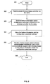
- FIG. 4 is a flow chart illustrating exemplary steps for providing self healing utilizing wireless access point radios integrated in a cable, in accordance with an embodiment of the invention.
- the exemplary steps start at step 401.
- the processor 208 in the wireless AP radio 200 integrated in the cable 201 may be operable to monitor and/or verify operations of one or more adjacent wireless AP radios integrated in the cable 201.
- the detection of a non-operational or defective adjacent wireless AP radio is checked. In instances when a non-operational adjacent wireless AP radio is detected, the exemplary steps may proceed to step 404.
- the transmission power of the antenna circuitry 212 in the wireless AP radio 200 may be increased for increasing coverage to cover at least a portion of coverage area associated with the non-operational adjacent wireless AP radio.
- the increase in the transmission power may be based on a new or updated power level setting received from a wireless controller such as the wireless controller 102.
- the exemplary steps may proceed to the end step 405.
- step 403 in instances when none of the one or more adjacent wireless AP radios is detected to be non-operational, the exemplary steps may proceed to step 402.
- a wireless AP radio 104a may be integrated in a cable 104 and the cable 104 may comprise one or more other integrated wireless AP radios 104b, 104c sharing the cable 104.
- the cable 104 may be communicatively coupled or connected to a wireless controller 102.
- the wireless AP radio 104a may receive power such as low voltage DC power from the wireless controller 102 via the cable 201.
- Feature information and/or configuration parameter settings may be received by the wireless AP radio 104a from the wireless controller 102 via the cable 104.
- the wireless AP radio 104a may be operable to provide wireless access and/or wireless communication services for one or more client devices 110 that are communicatively coupled to the wireless AP radio 104a, based on the received feature information and/or the received configuration parameter settings.
- the wireless AP radio 104a may provide the wireless access and/or wireless communication services using IEEE 802.11 standards, for example.
- the configuration parameter settings may comprise, for example, power level setting, channel setting, security setting and/or other configurable parameter settings.
- the wireless AP radio 104a may provide access to a wired network 101 for the one or more client devices 110.
- the wired network 101 may be communicatively coupled or connected to the wireless controller 102.
- the wireless AP radio 104 may receive a data packet having a wireless format such as a 802.11 format from each of the one or more client devices 110 such as the client device 110a, and transmit the data packet having the wireless format to the wireless controller 102 via the cable 104.
- the wireless controller 102 may convert the received data packet having the wireless format such as the 802.11 format to generate a data packet having a wired format such as a 802.3 format for transmitting to the wired network 101.
- the wired network 101 may transmit a data packet having a wired format such as the 802.3 format to the wireless controller 102.
- the wireless controller 102 may convert the received data packet having the wired format to generate a data packet having a wireless format such as the 802.11 format.
- the wireless controller 102 may transmit the data packet having the wireless format such as the 802.11 format to the wireless AP radio 104a via the cable 104.
- the wireless AP radio 104a may then transmit the received data packet having the wireless format such as the 802.11 format to each of the one or more client devices 110.
- the wireless controller 102 may discover or identify the wireless AP radio 104a integrated in the cable 104 based on a unique MAC address of the wireless AP radio 104a. Upgraded feature information and/or updated configuration parameter settings may also be received by the wireless AP radio 104a from the wireless controller 102 via the cable 104.
- the wireless AP radio 104a may be operable to monitor and/or verify operations of one or more adjacent wireless AP radios such as the wireless AP radio 104b integrated in the cable 104.
- the wireless AP radio 104a may be instructed by the wireless controller 102 to increase its transmission power to increase its coverage for covering at least a portion of coverage area associated with the one or more non-operational adjacent wireless AP radios such as the wireless AP radio 104b.
- One or more new cables such as the new cable 106, that each comprises one or more new wireless AP radios, such as the new wireless AP radios 106a - 106b, may be added to the cable 104 so as to extend a total coverage area associated with the wireless AP radios 104a and the one or more other wireless AP radios 104b - 104c in the cable 104.
- a section 104s of the cable 104 comprising the wireless AP radio 104a may be replaced by a new cable 108 comprising one or more new wireless AP radios, such as the new wireless AP radio 108a.
- inventions may provide a non-transitory computer readable medium and/or storage medium, and/or a non-transitory machine readable medium and/or storage medium, having stored thereon, a machine code and/or a computer program having at least one code section executable by a machine and/or a computer, thereby causing the machine and/or computer to perform the steps as described herein for wireless access point radios integrated in a cable.
- the present invention may be realized in hardware, software, or a combination of hardware and software.
- the present invention may be realized in a centralized fashion in at least one computer system or in a distributed fashion where different elements are spread across several interconnected computer systems. Any kind of computer system or other apparatus adapted for carrying out the methods described herein is suited.
- a typical combination of hardware and software may be a general-purpose computer system with a computer program that, when being loaded and executed, controls the computer system such that it carries out the methods described herein.
- the present invention may also be embedded in a computer program product, which comprises all the features enabling the implementation of the methods described herein, and which when loaded in a computer system is able to carry out these methods.
- Computer program in the present context means any expression, in any language, code or notation, of a set of instructions intended to cause a system having an information processing capability to perform a particular function either directly or after either or both of the following: a) conversion to another language, code or notation; b) reproduction in a different material form.
Abstract
Description
- [Not applicable]
- Certain embodiments of the invention relate to communication systems. More specifically, certain embodiments of the invention relate to a method and system for wireless access point radios integrated in a cable.
- A wireless access point (AP) is a primary network access device of a wireless network such as a wireless local area network (LAN). The wireless AP enables one or more wireless communication devices to access the wireless LAN using exemplary wireless communication standards such as WiFi, Bluetooth, 60 GHz, ZigBee and/or picocell cellular. Wireless APs are operable to support one or more wireless communication standards for sending and receiving data utilizing radio frequencies (RF) rather than cabling. For example, wireless APs may use standards defined by IEEE such as IEEE 802.11 standards.
- In an enterprise or corporate environment, several wireless APs may be communicatively coupled to a wired network such as a wired local area network (LAN), thereby providing wireless access to the wired network. A wireless AP may also be used in a home wireless network for connecting wireless enabled computers and/or other wireless communication devices in a home. In such instances, the wireless AP may be integrated in a wireless router which may include the wireless AP, a router, an Ethernet switch and/or a broadband modem.
- In an area such as in an unban area, the density of wireless APs may be high, and the same industrial, scientific and medical (ISM) spectrum may be shared by hundreds of wireless APs. In this regard, the higher the density of the wireless APs is, the lesser the bandwidth that may be available to each of the wireless APs.
- The actual coverage or range of the wireless AP may vary depending on such variables as indoor or outdoor environment, height above ground, nearby obstructions, interference from other active devices broadcasting on the same frequency, type of antenna, the current weather, operating radio frequency, and/or the power output of the wireless AP.
- Further limitations and disadvantages of conventional and traditional approaches will become apparent to one of skill in the art, through comparison of such systems with the present invention as set forth in the remainder of the present application with reference to the drawings.
- A system and/or method for wireless access point radios integrated in a cable, substantially as shown in and/or described in connection with at least one of the figures, as set forth more completely in the claims.
According to an aspect, a method for communication is provided, the method comprising: - in a wireless access point (AP) radio that is integrated in a cable, wherein said cable comprises one or more other integrated wireless AP radios sharing said cable, and said cable is communicatively coupled to a wireless controller:
- receiving power from said wireless controller via said cable;
- receiving feature information and/or configuration parameter settings from said wireless controller via said cable; and
- providing wireless access and/or wireless communication services for one or more client devices that are communicatively coupled to said wireless AP
- radio based on said received feature information and/or said received configuration parameter settings.
- receiving a data packet having a wireless format from each of said one or more client devices; and
- transmitting said data packet having said wireless format to said wireless controller via said cable, wherein said wireless controller converts said data packet having said wireless format to generate a data packet having a wired format for transmitting to said wired network.
- receiving a data packet having a wireless format from said wireless controller via said cable, wherein said wireless controller has converted a data packet having a wired format to generate said data packet having said wireless format after receiving said data packet having said wired format from said wired network; and
- transmitting said data packet having said wireless format to each of said one or more client devices.
- one or more processors and/or circuits for use in a wireless access point (AP) radio that is integrated in a cable, wherein said cable comprises one or more other integrated wireless AP radios sharing said cable, said cable is communicatively coupled to a wireless controller, and said one or more processors and/or circuits are operable to:
- receive power from said wireless controller via said cable;
- receive feature information and/or configuration parameter settings from said wireless controller via said cable; and
- provide wireless access and/or wireless communication services for one or more client devices that are communicatively coupled to said wireless AP radio based on said received feature information and/or said received configuration parameter settings.
- receive a data packet having a wireless format from each of said one or more client devices; and
- transmit said data packet having said wireless format to said wireless controller via said cable, and said wireless controller converts said data packet having said wireless format to generate a data packet having a wired format for transmitting to said wired network.
- receive a data packet having a wireless format from said wireless controller via said cable, and said wireless controller has converted a data packet having a wired format to generate said data packet having said wireless format after receiving said data packet having said wired format from said wired network; and
- transmit said data packet having said wireless format to each of said one or more client devices.
- Various advantages, aspects and novel features of the present invention, as well as details of an illustrated embodiment thereof, will be more fully understood from the following description and drawings.
-
FIG. 1A is a block diagram illustrating an exemplary communication system that is operable to provide wireless access point radios integrated in a cable, in accordance with an embodiment of the invention. -
FIGS. 1B - 1C are block diagrams that each illustrates exemplary coverage of wireless access point radios integrated in a cable, in accordance with an embodiment of the invention. -
FIG. 2 is a block diagram illustrating an exemplary wireless access point radio integrated in a cable, in accordance with an embodiment of the invention. -
FIG. 3 is a flow chart illustrating exemplary steps for providing wireless access point radios integrated in a cable, in accordance with an embodiment of the invention. -
FIG. 4 is a flow chart illustrating exemplary steps for providing self healing utilizing wireless access point radios integrated in a cable, in accordance with an embodiment of the invention. - Certain embodiments of the invention can be found in a method and system for wireless access point radios integrated in a cable. In various embodiments of the invention, a wireless access point (AP) radio may be integrated in a cable and the cable may comprise one or more other integrated wireless AP radios sharing the cable. The wireless AP radio may comprise one or more wireless transmitters and one or more wireless receivers. The cable may be communicatively coupled to a wireless controller and the wireless AP radio may be operable to receive power from the wireless controller via the cable. Feature information and/or configuration parameter settings may be received by the wireless AP radio from the wireless controller via the cable. The wireless AP radio may be operable to provide wireless access and/or wireless communication services for one or more client devices that are communicatively coupled to the wireless AP radio, based on the received feature information and/or the received configuration parameter settings.
- In an exemplary embodiment of the invention, the wireless AP radio may provide access to a wired network for the one or more client devices. The wired network may be connected to the wireless controller. In such instances, the wireless AP radio may receive a data packet having a wireless format from each of the one or more client devices, and transmit the data packet having the wireless format to the wireless controller via the cable. In this regard, the wireless controller may convert the received data packet having the wireless format to generate a data packet having a wired format for transmitting to the wired network. The wireless AP radio may receive a data packet having a wireless format from the wireless controller via the cable, and transmit the data packet having the wireless format to each of the one or more client devices. In this regard, the wireless controller may have converted a data packet having a wired format to generate the data packet having the wireless format after receiving the data packet in the wired format from the wired network.
- In an exemplary embodiment of the invention, the wireless controller may identify the wireless AP radio integrated in the cable based on a media access control (MAC) address of the wireless AP radio. Upgraded feature information and/or updated configuration parameter settings may be received by the wireless AP radio from the wireless controller via the cable. The wireless AP radio may be operable to monitor and/or verify operations of one or more adjacent wireless AP radios integrated in the cable. In instances when one or more adjacent wireless AP radios integrated in the cable may become non-operational, the wireless AP radio may increase its transmission power to increase its coverage for covering at least a portion of coverage area associated with the one or more non-operational adjacent wireless AP radios.
- One or more new cables that each comprises one or more new wireless AP radios may be added to the cable so as to extend a total coverage area associated with the wireless AP radio and the one or more other wireless AP radios in the cable. In instances when the wireless AP radio integrated in the cable is defective, a section of the cable comprising the wireless AP radio may be replaced by a new cable comprising one or more new wireless AP radios.
-
FIG. 1A is a block diagram illustrating an exemplary communication system that is operable to provide wireless access point radios integrated in a cable, in accordance with an embodiment of the invention. Referring toFIG. 1A , there is shown acommunication system 100. The communication system may comprise awired network 101, awireless controller 102, a plurality of cables, of whichcables client devices 110a - 110c are illustrated. Theclient device 110a ― 110c may be communicatively coupled to thewireless AP radio 104a. Thecables wireless AP radios 104a ― 104c and thewireless AP radios 114a ― 114d are illustrated, respectively. Each of thewireless AP radios 104a - 104c, 114a - 114d may be placed apart at a short distance such as at 1 - 3 meters. The integrated wireless AP radios such as thewireless AP radios 104a ― 104c may be a set of miniature wireless radios connected together by thecable 104. In this regard, for example, thewireless AP radios 104a - 104c may be connected together inside thecable 104. Thewireless AP radios 104a ― 104c may also be connected together by thecable 104 in a Christmas lights structure, for example. - The
wired network 101 may comprise suitable logic, circuitry, interfaces, communication devices and/or code that may be operable to provide communication and/or networking services to various devices such as thewireless controller 102 using wired technologies. For example, thewired network 101 may be an Ethernet network which may communicate data packets with thewireless controller 102 using IEEE 802.3 standards. - The
wireless controller 102 may comprise suitable logic, circuitry, interfaces and/or code that may be operable to provide management and/or control functionalities to a plurality of wireless AP radios such as thewireless AP radios 104a - 104c, 114a - 114d, which are communicatively coupled to thewireless controller 102 via thecables wireless controller 102 may be operable to discover or identify a wireless AP radio such as thewireless AP radio 104a connected to thewireless control 102 via thecable 104. Thewireless controller 102 may identify thewireless AP radio 104a based on a MAC address of thewireless AP radio 104a, for example. Thewireless controller 102 may provide power such as low voltage DC power to thewireless AP radio 104a via thecable 104. Thewireless controller 102 may download feature information and/or configuration parameter settings to thewireless AP radio 104a, via thecable 104. Thewireless AP radio 104a may then utilize the feature information and the configuration parameter settings to provide wireless access and/or wireless communication services to theclient devices 110a ― 110c. - Each of the wireless AP radios such as the
wireless AP radio 104a may comprise suitable logic, circuitry, interfaces and/or code that may be operable to provide wireless access and/or wireless communication services to one or more communicatively coupled client devices such as theclient devices 110. Thewireless AP radio 104a may comprise one or more wireless transmitters and one or more wireless receivers. A wireless transmitter and a wireless receiver may be integrated together as a transceiver, for example. In an exemplary embodiment of the invention, thewireless AP radio 104a may be operable to provide, for the one ormore client devices 110, wireless access to a wired network such as thewired network 101 which is connected to thewireless controller 102. - In operation, the
wireless AP radio 104a along with otherwireless AP radios 104b - 104c are integrated in thecable 104. Thecable 104 may be connected to thewireless controller 102 and thewireless controller 102 may be communicatively coupled to thewired network 101. Thewireless AP radio 104a may receive power such as low voltage DC power from thewireless controller 102 via thecable 104. For example, the low voltage DC power may be received using power over Ethernet (POE). Feature information and/or configuration parameter settings may be downloaded to thewireless AP radio 104a from thewireless controller 102 via thecable 104. Thewireless AP radio 104a may be operable to provide wireless access and/or wireless communication services for one ormore client devices 110 that are communicatively coupled to thewireless AP radio 104a, based on the received feature information and/or the received configuration parameter settings. In this regard, thewireless AP radio 104a may provide the wireless access and/or wireless communication services using IEEE 802.11 standards, for example. The received feature information may comprise, for example, software and/or firmware that may implement features based on the IEEE 802.11 standards. In an embodiment of the invention, in addition to implementing features based on the IEEE 802.11 standards, the feature information may also comprise enterprise level features such as, for example, security, quality of service and/or other enterprise level management features. The configuration parameter settings may comprise, for example, power level setting, channel setting, security setting and/or other configurable parameter settings. - In an exemplary embodiment of the invention, the
wireless AP radio 104a may provide access to thewired network 101 for the one ormore client devices 110. Thewired network 101 may be connected to thewireless controller 102. To minimize processing and data storage requirements of thewireless AP radio 104a, data packets that are travelling in thecable 104 are the same data packets that are travelling wirelessly over the air. In such instances, thewireless AP radio 104 may receive a data packet having a wireless format from each of the one ormore client devices 110 such as theclient device 110a, and transmit the data packet having the wireless format to thewireless controller 102 via thecable 104. Thewireless controller 102 may convert the received data packet having the wireless format to generate a data packet having a wired format for transmitting to thewired network 101. In this regard, the data packet having a wireless format may comprise, for example, a data packet in the 802.11 format. The data packet having a wired format may comprise, for example, a data packet in the 802.3 format. - The
wired network 101 may transmit a data packet having a wired format such as the 802.3 format to thewireless controller 102. Thewireless controller 102 may convert the received data packet having the wired format to generate a data packet having a wireless format such as the 802.11 format. Thewireless controller 102 may transmit the data packet having the wireless format such as the 802.11 format to thewireless AP radio 104a via thecable 104. Thewireless AP radio 104a may then transmit the received data packet having the wireless format to a communicatively coupled client device such as theclient device 110a. In instances when theclient device 110a is in a power save mode and is not able to communicate with thewireless AP radio 104a at this time, thewireless controller 102 may hold on to the data packet and not transmit the data packet to thewireless AP radio 104a until theclient device 110a is back to an active mode, for example. - In an exemplary embodiment of the invention, the
wireless controller 102 may discover or identify thewireless AP radio 104a integrated in thecable 104 based on a unique MAC address of thewireless AP radio 104a. Upgraded feature information and/or updated configuration parameter settings may also be received by thewireless AP radio 104a from thewireless controller 102 via thecable 104. Thewireless AP radio 104a may be operable to monitor and/or verify operations of one or more adjacent wireless AP radios such as thewireless AP radio 104b integrated in thecable 104. In instances when one or more adjacent wireless AP radios such as thewireless AP radio 104b may be detected to be non-operational or defective, thewireless AP radio 104a may be instructed by thewireless controller 102 to increase its transmission power to increase its coverage for covering at least a portion of coverage area associated with the one or more non-operational adjacent wireless AP radios such as thewireless AP radio 104b. For example, thewireless AP radio 104a may increase its transmission power based on a new or updated power level setting received from thewireless controller 102. - One or more new cables that each comprises one or more new wireless AP radios may be added to the
cable 104 so as to extend a total coverage area associated with thewireless AP radios 104a - 104c in thecable 104. For example, a new cable such as thenew cable 106, which may comprise newwireless AP radios 106a - 106b, may be added or connected to thecable 104, using splicing, for extending the total coverage area. - In instances when the
wireless AP radio 104a integrated in thecable 104 is defective, a section of thecable 104 comprising thewireless AP radio 104a may be replaced by a new cable comprising one or more new wireless AP radios. For example, asection 104s of thecable 104 may be replaced by a new cable such as thenew cable 108 which may comprise a newwireless AP radio 108a. - In the exemplary embodiment of the invention illustrated in
FIG. 1A , thewireless AP radio 104a provides wireless access for theclient devices 110 to thewired network 101 via thecable 104. Notwithstanding, the invention is not so limited and other wireless communication services may be provided by thewireless AP radio 104a. In this regard, for example, thewireless AP radio 104a along with the otherwireless AP radios 104b - 104c, 114a - 114d may form a mesh network, and a data packet received from theclient device 110a may travel via the mesh network over the air until the data packet reaches a destination. Due to the relatively short range coverage provided by thewireless AP radio 104a, thewireless AP radio 104a may be able to provide an accurate location such as an indoor location to theclient device 110a for location based services (LBS) applications, for example. -
FIGS. 1B ― 1C are block diagrams that each illustrates exemplary coverage of wireless access point radios integrated in a cable, in accordance with an embodiment of the invention. These scenarios are provided by way of exemplary illustration and not of limitation. Referring to each ofFIGS. 1B ― 1C, there is shown thewireless controller 102, thecable 104 and thewireless AP radios 104a - 104c described above with respect toFIG. 1A . Each of thewireless AP radio cable 104. -
FIG. 1B illustrates a first exemplary scenario in which all thewireless AP radios wireless AP radios coverage 116a,coverage 116b andcoverage 116c. Each of thewireless AP radios wireless controller 102 via thecable 104. Thewireless AP radio 104a may monitor and/or verify the operation of thewireless AP radio 104b. Thewireless AP radio 104b may monitor and/or verify the operations of thewireless AP radios wireless AP radio 104c may monitor and/or verify the operation of thewireless AP radio 104b. -
FIG. 1C illustrates a second exemplary scenario in which thewireless AP radios wireless AP radio 104b is detected to be non-operational or defective. In such an instance, each of thewireless AP radios wireless controller 102. Thewireless AP radio 104a may increase its transmission power, based on the received power level setting, to increase its coverage for covering a portion of coverage area associated with thewireless AP radio 104b, as illustrated bycoverage 118a. Thewireless AP radio 104c may increase its transmission power, based on the received power level setting, to increase its coverage for covering a portion of coverage area associated with thewireless AP radio 104b, as illustrated bycoverage 118c. Accordingly, the coverage area associated with the non-operational or defectivewireless AP radio 104b may be covered by the adjacentwireless AP radios -
FIG. 2 is a block diagram illustrating an exemplary wireless access point radio integrated in a cable, in accordance with an embodiment of the invention. Referring toFIG. 2 , there is shown awireless AP radio 200 integrated in acable 201. Thewireless radio 200 may comprise awireless transmitter 202, awireless receiver 205, aPHY module 204, aMAC module 206, aprocessor 208, a memory and anantenna circuitry 212. Thecable 201 may comprisewires 203. Thewireless AP radio 200 may be substantially similar to, for example, thewireless AP radio 104a inFIG. 1A . Thecable 201 may be substantially similar to, for example, thecable 104 inFIG. 1A . - The
wires 203, which may be, for example, a pair of copper wires, may provide a medium for connecting thewireless AP radio 200 with other wireless AP radios integrated in thecable 201. Thewires 203 may provide thewireless AP radio 200 with a shared medium for receiving a low voltage DC power from a wireless controller such as thewireless controller 102 as well as communicating data packets with thewireless controller 102 and/or other wireless AP radios integrated in thecable 201. - The
wireless transmitter 202 may comprise suitable logic, circuitry, interfaces and/or code that may be operable to transmit radio signals based on one or more radio access standards such as, for example, WiFi, Bluetooth, ZigBee, picocell cellular and/or 60 GHz. Thewireless transmitter 202 may communicatively coupled with theantenna circuitry 212. In an exemplary embodiment of the invention, thewireless transmitter 202 may communicate data packets with one or more client devices such as theclient devices 110 via theantenna circuitry 212. - The
wireless receiver 205 may comprise suitable logic, circuitry, interfaces and/or code that may be operable to receive radio signals based on one or more radio access standards such as, for example, WiFi, Bluetooth, ZigBee, picocell cellular and/or 60 GHz. Thewireless receiver 205 may communicatively coupled with theantenna circuitry 212. In an exemplary embodiment of the invention, thewireless receiver 205 may communicate data packets with one or more client devices such as theclient devices 110 via theantenna circuitry 212. - The
PHY module 204 may comprise suitable logic, circuitry, interfaces and/or code that may be operable to implement the operability and/or functionality of layer 1 or physical layer of open systems interconnection (OSI) network model. ThePHY module 204 may be operable to handle physical layer requirements, which may comprise, but are not limited to, packetization, data transfer and/or serialization/deserialization (SERDES), in instances where such an operation is required. In an exemplary embodiment of the invention, thePHY module 204 may encode data packets that are to be transmitted to thewireless controller 102 via thewires 203 and/or to decode data packets received from thewireless controller 102 via thewires 203. - The
MAC module 206 may comprise suitable logic, circuitry, interfaces and/or code that may be operable to implement the operability and/or functionality of layer 2 or data link layer of OSI network model. TheMAC module 206 may communicate with thePHY module 204 via parallel and/or serial links, for example. TheMAC module 206 may provide addressing and channel access control mechanisms. In an exemplary embodiment of the invention, a MAC address provided by theMAC module 206 may be utilized by a wireless controller such as thewireless controller 102 for discovering or identifying thewireless AP radio 200 integrated in thecable 201. - The
processor 208 may comprise suitable logic, circuitry, interfaces and/or code that may be operable to manage and/or control operations of various components in thewireless AP radio 200 such as, for example, thewireless transmitter 202, thewireless receiver 205, theantenna circuitry 212, thePHY module 204 and/or theMAC module 206. Theprocessor 208 may process signals associated with thewireless transmitter 202, thewireless receiver 205, thePHY module 204 and/or theMAC modules 206. In an exemplary embodiment of the invention, theprocessor 208 may be operable to monitor and/or verify operations of one or more adjacent wireless AP radios which are integrated in thecable 210 and connected to thewires 203. - The
memory 210 may comprise suitable logic, circuitry, interfaces and/or code that may be operable to store information such as executable instructions and/or data that may be utilized by theprocessor 208. Thememory 210 may comprise RAM and/or ROM. In an exemplary embodiment of the invention, after thewireless AP radio 200 receives power from a wireless controller such as thewireless controller 102 via thewires 203, thememory 210 may be operable to store feature information and configuration parameters settings which may be downloaded from thewireless controller 102 via thePHY module 204 and thewires 203. Thememory 210 may also store upgraded feature information and updated configuration parameter settings which may be received from thewireless controller 102 via thePHY module 204 and thewires 203. In an exemplary embodiment of the invention, thememory 210 may comprise volatile storage. Accordingly, after thewireless AP radio 200 is powered down, the feature information stored in the volatile storage may be lost and the configuration parameter settings stored in the volatile storage may be reset to default settings, for example. - The
antenna circuitry 212 may comprise suitable logic, circuitry, interfaces and/or code that may be operable to provide antenna functionality for thewireless AP radio 200. Theantenna circuitry 212 may communicatively coupled with thewireless transmitter 202 and/or thewireless receiver 205. Theantenna circuitry 212 may comprise, for example a fractal antenna, a PCB antenna, and/or a dipole antenna. The transmission power of theantenna circuitry 212 may be managed and controlled by theprocessor 208. - In operation, the
wireless AP radio 200 may receive power such as low voltage DC power, via thewires 203 from a wireless controller such as thewireless controller 102. Thewireless AP radio 200 may receive feature information and/or configuration parameter settings, via thePHY module 204 and thewires 203, from thewireless controller 102. The received feature information and/or the received configuration parameter settings may be stored in thememory 210 for theprocessor 208 to use. Theprocessor 208 may be operable to communicate data packets such as 802.11 data packets with one or more client devices such as theclient devices 110 via thewireless transmitter 202, thewireless receiver 205 and theantenna circuitry 212. Theprocessor 208 may be operable to communicate data packets such as 802.11 data packets with thewireless controller 102 via thePHY module 204 and thewires 203. Thewireless AP radio 200 may also receive upgraded feature information and/or updated configuration parameter settings from thewireless controller 102 via thewires 203 and thePHY module 204. Thewireless controller 102 may discover or identify thewireless AP radio 200 based on a MAC address provided by theMAC module 206. - The
processor 208 may be operable to monitor and/or verify operations of one or more adjacent wireless AP radios integrated in thecable 201 and connected to thewires 203. In instances when one or more adjacent wireless AP radios may be detected to be non-operational or defective, theprocessor 208 may manage and/or control the increase of the transmission power of theantenna circuitry 212 based on a new or updated power level setting received via thePHY module 204 and thewires 203. The increased transmission power of theantenna circuitry 212 may increase coverage of thewireless AP radio 200 so as to cover at least a portion of coverage area associated with the one or more non-operational adjacent wireless AP radios. -
FIG. 3 is a flow chart illustrating exemplary steps for providing wireless access point radios integrated in a cable, in accordance with an embodiment of the invention. Referring toFIG. 3 , the exemplary steps start atstep 301. Instep 302, thewireless AP radio 200, which is integrated in thecable 201, may be operable to receiver power such as low voltage DC power from a wireless controller such as thewireless controller 102 via thecable 201. The power may be received via thewires 203. Instep 303, thewireless AP radio 200 may receive feature information and/or configuration parameter settings from thewireless controller 102 via thecable 201. The feature information and/or the configuration parameter settings may be received via thewires 203 in thecable 201 and thePHY module 204 in thewireless AP radio 200. Instep 304, the received feature information and the configuration parameter settings may be stored in thememory 210 in thewireless AP radio 200. Instep 305, thewireless AP radio 200 may provide wireless access and/or wireless communication services for one or more communicatively coupled client devices such as thedevices 110, based on the feature information and/or the configuration parameter settings. Thewireless AP radio 200 may communicate with theclient devices 100 via thewireless transmitter 202, thewireless receiver 205 and theantenna circuitry 212 in thewireless AP radio 200. The exemplary steps may proceed to theend step 306. -
FIG. 4 is a flow chart illustrating exemplary steps for providing self healing utilizing wireless access point radios integrated in a cable, in accordance with an embodiment of the invention. Referring toFIG. 4 , the exemplary steps start atstep 401. Instep 402, theprocessor 208 in thewireless AP radio 200 integrated in thecable 201 may be operable to monitor and/or verify operations of one or more adjacent wireless AP radios integrated in thecable 201. Instep 403, the detection of a non-operational or defective adjacent wireless AP radio is checked. In instances when a non-operational adjacent wireless AP radio is detected, the exemplary steps may proceed to step 404. Instep 404, the transmission power of theantenna circuitry 212 in thewireless AP radio 200 may be increased for increasing coverage to cover at least a portion of coverage area associated with the non-operational adjacent wireless AP radio. The increase in the transmission power may be based on a new or updated power level setting received from a wireless controller such as thewireless controller 102. The exemplary steps may proceed to theend step 405. Instep 403, in instances when none of the one or more adjacent wireless AP radios is detected to be non-operational, the exemplary steps may proceed to step 402. - In various embodiments of the invention, a
wireless AP radio 104a may be integrated in acable 104 and thecable 104 may comprise one or more other integratedwireless AP radios cable 104. Thecable 104 may be communicatively coupled or connected to awireless controller 102. Thewireless AP radio 104a may receive power such as low voltage DC power from thewireless controller 102 via thecable 201. Feature information and/or configuration parameter settings may be received by thewireless AP radio 104a from thewireless controller 102 via thecable 104. Thewireless AP radio 104a may be operable to provide wireless access and/or wireless communication services for one ormore client devices 110 that are communicatively coupled to thewireless AP radio 104a, based on the received feature information and/or the received configuration parameter settings. In this regard, thewireless AP radio 104a may provide the wireless access and/or wireless communication services using IEEE 802.11 standards, for example. The configuration parameter settings may comprise, for example, power level setting, channel setting, security setting and/or other configurable parameter settings. - In an exemplary embodiment of the invention, the
wireless AP radio 104a may provide access to awired network 101 for the one ormore client devices 110. Thewired network 101 may be communicatively coupled or connected to thewireless controller 102. In such instances, thewireless AP radio 104 may receive a data packet having a wireless format such as a 802.11 format from each of the one ormore client devices 110 such as theclient device 110a, and transmit the data packet having the wireless format to thewireless controller 102 via thecable 104. Thewireless controller 102 may convert the received data packet having the wireless format such as the 802.11 format to generate a data packet having a wired format such as a 802.3 format for transmitting to thewired network 101. - The
wired network 101 may transmit a data packet having a wired format such as the 802.3 format to thewireless controller 102. Thewireless controller 102 may convert the received data packet having the wired format to generate a data packet having a wireless format such as the 802.11 format. Thewireless controller 102 may transmit the data packet having the wireless format such as the 802.11 format to thewireless AP radio 104a via thecable 104. Thewireless AP radio 104a may then transmit the received data packet having the wireless format such as the 802.11 format to each of the one ormore client devices 110. - In an exemplary embodiment of the invention, the
wireless controller 102 may discover or identify thewireless AP radio 104a integrated in thecable 104 based on a unique MAC address of thewireless AP radio 104a. Upgraded feature information and/or updated configuration parameter settings may also be received by thewireless AP radio 104a from thewireless controller 102 via thecable 104. Thewireless AP radio 104a may be operable to monitor and/or verify operations of one or more adjacent wireless AP radios such as thewireless AP radio 104b integrated in thecable 104. In instances when one or more adjacent wireless AP radios such as thewireless AP radio 104b may be detected to be non-operational or defective, thewireless AP radio 104a may be instructed by thewireless controller 102 to increase its transmission power to increase its coverage for covering at least a portion of coverage area associated with the one or more non-operational adjacent wireless AP radios such as thewireless AP radio 104b. - One or more new cables, such as the
new cable 106, that each comprises one or more new wireless AP radios, such as the newwireless AP radios 106a - 106b, may be added to thecable 104 so as to extend a total coverage area associated with thewireless AP radios 104a and the one or more otherwireless AP radios 104b - 104c in thecable 104. - In instances when the
wireless AP radio 104a integrated in thecable 104 is defective, asection 104s of thecable 104 comprising thewireless AP radio 104a may be replaced by anew cable 108 comprising one or more new wireless AP radios, such as the newwireless AP radio 108a. - Other embodiments of the invention may provide a non-transitory computer readable medium and/or storage medium, and/or a non-transitory machine readable medium and/or storage medium, having stored thereon, a machine code and/or a computer program having at least one code section executable by a machine and/or a computer, thereby causing the machine and/or computer to perform the steps as described herein for wireless access point radios integrated in a cable.
- Accordingly, the present invention may be realized in hardware, software, or a combination of hardware and software. The present invention may be realized in a centralized fashion in at least one computer system or in a distributed fashion where different elements are spread across several interconnected computer systems. Any kind of computer system or other apparatus adapted for carrying out the methods described herein is suited. A typical combination of hardware and software may be a general-purpose computer system with a computer program that, when being loaded and executed, controls the computer system such that it carries out the methods described herein.
- The present invention may also be embedded in a computer program product, which comprises all the features enabling the implementation of the methods described herein, and which when loaded in a computer system is able to carry out these methods. Computer program in the present context means any expression, in any language, code or notation, of a set of instructions intended to cause a system having an information processing capability to perform a particular function either directly or after either or both of the following: a) conversion to another language, code or notation; b) reproduction in a different material form.
- While the present invention has been described with reference to certain embodiments, it will be understood by those skilled in the art that various changes may be made and equivalents may be substituted without departing from the scope of the present invention. In addition, many modifications may be made to adapt a particular situation or material to the teachings of the present invention without departing from its scope. Therefore, it is intended that the present invention not be limited to the particular embodiment disclosed, but that the present invention will include all embodiments falling within the scope of the appended claims.
Advantageously, the method further comprises:
Advantageously, the method further comprises monitoring and/or verifying operations of one or more adjacent wireless AP radios integrated in said cable.
Advantageously, the method further comprises, when one or more adjacent wireless AP radios integrated in said cable become non-operational, increasing transmission power of said wireless AP radio to increase a coverage of said wireless AP radio for covering at least a portion of coverage area associated with said one or more non-operational adjacent wireless AP radios.
Advantageously, the method further comprises receiving upgraded feature information and/or updated configuration parameter settings from said wireless controller via said cable.
Advantageously, one or more new cables that each comprises one or more new wireless AP radios are added to said cable to extend a total coverage area associated with said wireless AP radio and said one or more other wireless AP radios in said cable.
Advantageously, when said wireless AP radio integrated in said cable is defective, a section of said cable comprising said wireless AP radio is replaced by a new cable comprising one or more new wireless AP radios.
According to a further aspect, a system for communication comprises:
Advantageously, said one or more processors and/or circuits are operable to:
Advantageously, said one or more processors and/or circuits are operable to monitor and/or verify operations of one or more adjacent wireless AP radios integrated in said cable.
Advantageously, when one or more adjacent wireless AP radios integrated in said cable become non-operational, said one or more processors and/or circuits are operable to increase transmission power of said wireless AP radio to increase a coverage of said wireless AP radio for covering at least a portion of coverage area associated with said one or more non-operational adjacent wireless AP radios.
Advantageously, said one or more processors and/or circuits are operable to receive upgraded feature information and/or updated configuration parameter settings from said wireless controller via said cable.
Advantageously, one or more new cables that each comprises one or more new wireless AP radios are added to said cable to extend a total coverage area associated with said wireless AP radio and said one or more other wireless AP radios in said cable.
Advantageously, when said wireless AP radio integrated in said cable is defective, a section of said cable comprising said wireless AP radio is replaced by a new cable comprising one or more new wireless AP radios.
Claims (15)
- A method for communication, the method comprising:in a wireless access point (AP) radio that is integrated in a cable, wherein said cable comprises one or more other integrated wireless AP radios sharing said cable, and said cable is communicatively coupled to a wireless controller:receiving power from said wireless controller via said cable;receiving feature information and/or configuration parameter settings from said wireless controller via said cable; andproviding wireless access and/or wireless communication services for one or more client devices that are communicatively coupled to said wireless AP radio based on said received feature information and/or said received configuration parameter settings.
- The method according to claim 1, comprising providing wireless access to a wired network which is connected to said wireless controller for said one or more client devices.
- The method according to claim 2, comprising:receiving a data packet having a wireless format from each of said one or more client devices; andtransmitting said data packet having said wireless format to said wireless controller via said cable, wherein said wireless controller converts said data packet having said wireless format to generate a data packet having a wired format for transmitting to said wired network.
- The method according to claim 2, comprising:receiving a data packet having a wireless format from said wireless controller via said cable, wherein said wireless controller has converted a data packet having a wired format to generate said data packet having said wireless format after receiving said data packet having said wired format from said wired network; andtransmitting said data packet having said wireless format to each of said one or more client devices.
- The method according to claim 1, wherein said wireless controller identifies said wireless AP radio based on a media access control (MAC) address of said wireless AP radio.
- The method according to claim 1, comprising monitoring and/or verifying operations of one or more adjacent wireless AP radios integrated in said cable.
- The method according to claim 1, comprising, when one or more adjacent wireless AP radios integrated in said cable become non-operational, increasing transmission power of said wireless AP radio to increase a coverage of said wireless AP radio for covering at least a portion of coverage area associated with said one or more non-operational adjacent wireless AP radios.
- The method according to claim 1, comprising receiving upgraded feature information and/or updated configuration parameter settings from said wireless controller via said cable.
- The method according to claim 1, wherein one or more new cables that each comprises one or more new wireless AP radios are added to said cable to extend a total coverage area associated with said wireless AP radio and said one or more other wireless AP radios in said cable.
- The method according to claim 1, wherein, when said wireless AP radio integrated in said cable is defective, a section of said cable comprising said wireless AP radio is replaced by a new cable comprising one or more new wireless AP radios.
- A system for communication, the system comprising:one or more processors and/or circuits for use in a wireless access point (AP) radio that is integrated in a cable, wherein said cable comprises one or more other integrated wireless AP radios sharing said cable, said cable is communicatively coupled to a wireless controller, and said one or more processors and/or circuits are operable to:receive power from said wireless controller via said cable;receive feature information and/or configuration parameter settings from said wireless controller via said cable; andprovide wireless access and/or wireless communication services for one or more client devices that are communicatively coupled to said wireless AP radio based on said received feature information and/or said received configuration parameter settings.
- The system according to claim 11, wherein said one or more processors and/or circuits are operable to provide wireless access to a wired network which is connected to said wireless controller for said one or more client devices.
- The system according to claim 12, wherein said one or more processors and/or circuits are operable to:receive a data packet having a wireless format from each of said one or more client devices; andtransmit said data packet having said wireless format to said wireless controller via said cable, and said wireless controller converts said data packet having said wireless format to generate a data packet having a wired format for transmitting to said wired network.
- The system according to claim 12, wherein said one or more processors and/or circuits are operable to:receive a data packet having a wireless format from said wireless controller via said cable, and said wireless controller has converted a data packet having a wired format to generate said data packet having said wireless format after receiving said data packet having said wired format from said wired network; andtransmit said data packet having said wireless format to each of said one or more client devices.
- The system according to claim 11, wherein said wireless controller identifies said wireless AP radio based on a media access control (MAC) address of said wireless AP radio.
Applications Claiming Priority (1)
| Application Number | Priority Date | Filing Date | Title |
|---|---|---|---|
| US12/984,949 US8867508B2 (en) | 2011-01-05 | 2011-01-05 | Method and system for wireless access point radios integrated in a cable |
Publications (2)
| Publication Number | Publication Date |
|---|---|
| EP2475218A1 true EP2475218A1 (en) | 2012-07-11 |
| EP2475218B1 EP2475218B1 (en) | 2019-07-03 |
Family
ID=45444355
Family Applications (1)
| Application Number | Title | Priority Date | Filing Date |
|---|---|---|---|
| EP11009947.0A Active EP2475218B1 (en) | 2011-01-05 | 2011-12-19 | Method and system for wireless access point radios integrated in a cable |
Country Status (5)
| Country | Link |
|---|---|
| US (1) | US8867508B2 (en) |
| EP (1) | EP2475218B1 (en) |
| KR (1) | KR101355061B1 (en) |
| CN (2) | CN108463011A (en) |
| TW (1) | TWI543657B (en) |
Families Citing this family (15)
| Publication number | Priority date | Publication date | Assignee | Title |
|---|---|---|---|---|
| US8913557B2 (en) | 2012-06-27 | 2014-12-16 | Broadcom Corporation | Distributed wireless extenders over home MoCA backbone |
| CN104519513A (en) * | 2013-09-30 | 2015-04-15 | 深圳市群云网络有限公司 | WLAN (wireless local area network)-based communication method and system |
| CN104519547B (en) * | 2013-09-30 | 2018-08-14 | 深圳市群云网络有限公司 | A kind of based on WLAN communication means and system |
| CN104519546B (en) * | 2013-09-30 | 2018-12-14 | 深圳市群云网络有限公司 | A kind of based on WLAN communication means and system |
| CN104519517B (en) * | 2013-09-30 | 2018-07-06 | 深圳市群云网络有限公司 | The method and system that wireless access point AP automatically configures in WLAN |
| US9560535B2 (en) * | 2013-10-03 | 2017-01-31 | Sercomm Corporation | Data stream generation and transmission system and method therefor |
| US10314088B2 (en) * | 2014-04-16 | 2019-06-04 | Belkin International, Inc. | Associating devices and users with a local area network using network identifiers |
| US10560975B2 (en) | 2014-04-16 | 2020-02-11 | Belkin International, Inc. | Discovery of connected devices to determine control capabilities and meta-information |
| KR101635182B1 (en) * | 2015-02-25 | 2016-06-30 | 영남대학교 산학협력단 | Cable type access point and location monitoring system using the same |
| CN106817679B (en) * | 2015-11-30 | 2020-09-25 | 乐高乐佳(北京)信息技术有限公司 | Network system for positioning service based on wireless communication technology |
| WO2017104925A1 (en) * | 2015-12-16 | 2017-06-22 | 에스케이플래닛 주식회사 | Wireless mesh network management method, device therefor, and recording medium in which computer program for executing same is recorded |
| WO2020185953A1 (en) | 2019-03-12 | 2020-09-17 | Epstein Joseph Alan | Radically inexpensive and flexible wireless deployment system and method |
| BR112023001123A2 (en) * | 2020-07-21 | 2023-03-28 | Omnifi Inc | FLEXIBLE WIRELESS INTERCONNECTION AND PLATE DIVERSITY |
| CN112260842A (en) * | 2020-09-07 | 2021-01-22 | 天地(常州)自动化股份有限公司 | Communication cable and data communication method |
| KR102425747B1 (en) * | 2022-01-11 | 2022-07-27 | 안세환 | Integrated wiring management system |
Citations (2)
| Publication number | Priority date | Publication date | Assignee | Title |
|---|---|---|---|---|
| GB2402023A (en) * | 2000-07-14 | 2004-11-24 | Ip Access Ltd | Maintaining frequency of a control channel in a cellular communication system |
| US7231224B1 (en) * | 2001-11-13 | 2007-06-12 | Atheros Communications, Inc. | Cable having embedded access points |
Family Cites Families (14)
| Publication number | Priority date | Publication date | Assignee | Title |
|---|---|---|---|---|
| US5809429A (en) * | 1995-09-22 | 1998-09-15 | Andrew Corporation | Radiating coaxial cable and radio communication system using same |
| US5994998A (en) * | 1997-05-29 | 1999-11-30 | 3Com Corporation | Power transfer apparatus for concurrently transmitting data and power over data wires |
| US7203183B2 (en) * | 2002-06-26 | 2007-04-10 | International Business Machines Corporation | Access point initiated forced roaming based upon bandwidth |
| JP2005192059A (en) | 2003-12-26 | 2005-07-14 | Matsushita Electric Ind Co Ltd | Wireless lan slave station device |
| EP1626537A1 (en) * | 2004-08-11 | 2006-02-15 | Iwatsu Electric Co., Ltd. | Wireless LAN network system and a method for connecting access points thereof |
| US20060079230A1 (en) | 2004-10-13 | 2006-04-13 | Russell Thomas C | System and methods for redundant networks |
| US20060153085A1 (en) * | 2004-12-27 | 2006-07-13 | Willins Bruce A | Method and system for recovery from access point infrastructure link failures |
| JP4972911B2 (en) * | 2005-11-18 | 2012-07-11 | 株式会社日立製作所 | RFID readers used in RFID built-in cable systems |
| WO2007089961A1 (en) * | 2006-01-31 | 2007-08-09 | Koninklijke Philips Electronics, N.V. | Remote antenna for wireless access point |
| WO2008054877A2 (en) * | 2006-05-17 | 2008-05-08 | Aerielle Technologies, Inc. | Antenna implementations in interconnecting cables |
| CN101174976B (en) * | 2006-10-31 | 2010-09-08 | 杭州华三通信技术有限公司 | Point-to-multipoint coaxial cable Ethernet transmission method, system and transmission apparatus |
| US8264355B2 (en) * | 2006-12-14 | 2012-09-11 | Corning Cable Systems Llc | RFID systems and methods for optical fiber network deployment and maintenance |
| CN102204014A (en) * | 2008-12-25 | 2011-09-28 | 西门子公司 | Active antenna device, network device and access point of a wireless network |
| CN201590832U (en) * | 2009-12-02 | 2010-09-22 | 北京东方信联无线通信有限公司 | Wideband access system, local area network terminal and terminal equipment |
-
2011
- 2011-01-05 US US12/984,949 patent/US8867508B2/en active Active
- 2011-12-19 EP EP11009947.0A patent/EP2475218B1/en active Active
-
2012
- 2012-01-05 CN CN201810204783.3A patent/CN108463011A/en active Pending
- 2012-01-05 CN CN2012100021704A patent/CN102655688A/en active Pending
- 2012-01-05 KR KR1020120001411A patent/KR101355061B1/en not_active IP Right Cessation
- 2012-01-05 TW TW101100402A patent/TWI543657B/en not_active IP Right Cessation
Patent Citations (2)
| Publication number | Priority date | Publication date | Assignee | Title |
|---|---|---|---|---|
| GB2402023A (en) * | 2000-07-14 | 2004-11-24 | Ip Access Ltd | Maintaining frequency of a control channel in a cellular communication system |
| US7231224B1 (en) * | 2001-11-13 | 2007-06-12 | Atheros Communications, Inc. | Cable having embedded access points |
Also Published As
| Publication number | Publication date |
|---|---|
| KR20120079818A (en) | 2012-07-13 |
| US8867508B2 (en) | 2014-10-21 |
| TWI543657B (en) | 2016-07-21 |
| EP2475218B1 (en) | 2019-07-03 |
| TW201247008A (en) | 2012-11-16 |
| CN102655688A (en) | 2012-09-05 |
| KR101355061B1 (en) | 2014-01-24 |
| CN108463011A (en) | 2018-08-28 |
| US20120170558A1 (en) | 2012-07-05 |
Similar Documents
| Publication | Publication Date | Title |
|---|---|---|
| EP2475218B1 (en) | Method and system for wireless access point radios integrated in a cable | |
| US11012831B2 (en) | Distributed multi-band wireless networking system | |
| US10798702B2 (en) | Periodic frames for control plane data to manage multi-band wireless networking system | |
| EP3326331B1 (en) | A centralized controlling system controlling interactions and cooperation between radio-operated devices operating in a mesh network supporting multiple radio communication protocols | |
| US9979626B2 (en) | Establishing a mesh network with wired and wireless links | |
| EP2350863B1 (en) | Establishing a mesh network with wired and wireless links | |
| EP3158692A1 (en) | Systems and methods for selecting an optimum communication route in a wireless network | |
| WO2019125396A1 (en) | Enhanced time sensitive networking for wireless communications | |
| US9693204B2 (en) | System and method for conveying information using broadcast frames | |
| CN111133825A (en) | Enhanced time sensitive network coordination for wireless transmissions | |
| US20220167272A1 (en) | Wake-up by a network device | |
| JP6432294B2 (en) | COMMUNICATION SYSTEM, COMMUNICATION SYSTEM CONTROL METHOD, AND PROGRAM | |
| CN111937350B (en) | Tuning topology for distribution grid | |
| US20180131401A1 (en) | Wireless sfp module | |
| US20220287049A1 (en) | Access point configured for signaling configuration and resource allocation inside a synchronized transmission opportunity (s-txop) | |
| US20220330270A1 (en) | Resource allocation and update for communicating within synchronized transmission opportunities (s-txops) | |
| US20220248486A1 (en) | Multi-link device classification based neighbor discovery | |
| WO2023239721A1 (en) | Cellular mesh network for remote radio units | |
| WO2023053376A1 (en) | Communication control system, communication control method, and communication device | |
| JP6788561B2 (en) | Wireless communication device and wireless communication method | |
| TWI670984B (en) | Network communication device, wireless access point, wireless repeater | |
| Ševerenka | Wireless network implementation in Pabiržis | |
| CN116801278A (en) | Tuning method, access controller, customer premises equipment and storage medium | |
| WO2022238153A1 (en) | A method of and a node device for communicating network information to an uncommissioned node device to be added to a network and a method of joining an uncommissioned node device into a network | |
| WO2019006075A1 (en) | Poe led lamp as a mobile access point |
Legal Events
| Date | Code | Title | Description |
|---|---|---|---|
| PUAI | Public reference made under article 153(3) epc to a published international application that has entered the european phase |
Free format text: ORIGINAL CODE: 0009012 |
|
| 17P | Request for examination filed |
Effective date: 20111219 |
|
| AK | Designated contracting states |
Kind code of ref document: A1 Designated state(s): AL AT BE BG CH CY CZ DE DK EE ES FI FR GB GR HR HU IE IS IT LI LT LU LV MC MK MT NL NO PL PT RO RS SE SI SK SM TR |
|
| AX | Request for extension of the european patent |
Extension state: BA ME |
|
| STAA | Information on the status of an ep patent application or granted ep patent |
Free format text: STATUS: EXAMINATION IS IN PROGRESS |
|
| RAP1 | Party data changed (applicant data changed or rights of an application transferred) |
Owner name: AVAGO TECHNOLOGIES GENERAL IP (SINGAPORE) PTE. LTD |
|
| RAP1 | Party data changed (applicant data changed or rights of an application transferred) |
Owner name: AVAGO TECHNOLOGIES INTERNATIONAL SALES PTE. LIMITE |
|
| RIC1 | Information provided on ipc code assigned before grant |
Ipc: H04W 24/04 20090101ALN20181203BHEP Ipc: H04W 88/08 20090101AFI20181203BHEP |
|
| GRAP | Despatch of communication of intention to grant a patent |
Free format text: ORIGINAL CODE: EPIDOSNIGR1 |
|
| STAA | Information on the status of an ep patent application or granted ep patent |
Free format text: STATUS: GRANT OF PATENT IS INTENDED |
|
| INTG | Intention to grant announced |
Effective date: 20190124 |
|
| GRAS | Grant fee paid |
Free format text: ORIGINAL CODE: EPIDOSNIGR3 |
|
| GRAA | (expected) grant |
Free format text: ORIGINAL CODE: 0009210 |
|
| STAA | Information on the status of an ep patent application or granted ep patent |
Free format text: STATUS: THE PATENT HAS BEEN GRANTED |
|
| AK | Designated contracting states |
Kind code of ref document: B1 Designated state(s): AL AT BE BG CH CY CZ DE DK EE ES FI FR GB GR HR HU IE IS IT LI LT LU LV MC MK MT NL NO PL PT RO RS SE SI SK SM TR |
|
| REG | Reference to a national code |
Ref country code: GB Ref legal event code: FG4D |
|
| REG | Reference to a national code |
Ref country code: CH Ref legal event code: EP Ref country code: AT Ref legal event code: REF Ref document number: 1152543 Country of ref document: AT Kind code of ref document: T Effective date: 20190715 |
|
| REG | Reference to a national code |
Ref country code: IE Ref legal event code: FG4D |
|
| REG | Reference to a national code |
Ref country code: DE Ref legal event code: R096 Ref document number: 602011060147 Country of ref document: DE |
|
| REG | Reference to a national code |
Ref country code: NL Ref legal event code: MP Effective date: 20190703 |
|
| REG | Reference to a national code |
Ref country code: LT Ref legal event code: MG4D |
|
| REG | Reference to a national code |
Ref country code: AT Ref legal event code: MK05 Ref document number: 1152543 Country of ref document: AT Kind code of ref document: T Effective date: 20190703 |
|
| PG25 | Lapsed in a contracting state [announced via postgrant information from national office to epo] |
Ref country code: FI Free format text: LAPSE BECAUSE OF FAILURE TO SUBMIT A TRANSLATION OF THE DESCRIPTION OR TO PAY THE FEE WITHIN THE PRESCRIBED TIME-LIMIT Effective date: 20190703 Ref country code: HR Free format text: LAPSE BECAUSE OF FAILURE TO SUBMIT A TRANSLATION OF THE DESCRIPTION OR TO PAY THE FEE WITHIN THE PRESCRIBED TIME-LIMIT Effective date: 20190703 Ref country code: SE Free format text: LAPSE BECAUSE OF FAILURE TO SUBMIT A TRANSLATION OF THE DESCRIPTION OR TO PAY THE FEE WITHIN THE PRESCRIBED TIME-LIMIT Effective date: 20190703 Ref country code: NO Free format text: LAPSE BECAUSE OF FAILURE TO SUBMIT A TRANSLATION OF THE DESCRIPTION OR TO PAY THE FEE WITHIN THE PRESCRIBED TIME-LIMIT Effective date: 20191003 Ref country code: BG Free format text: LAPSE BECAUSE OF FAILURE TO SUBMIT A TRANSLATION OF THE DESCRIPTION OR TO PAY THE FEE WITHIN THE PRESCRIBED TIME-LIMIT Effective date: 20191003 Ref country code: NL Free format text: LAPSE BECAUSE OF FAILURE TO SUBMIT A TRANSLATION OF THE DESCRIPTION OR TO PAY THE FEE WITHIN THE PRESCRIBED TIME-LIMIT Effective date: 20190703 Ref country code: LT Free format text: LAPSE BECAUSE OF FAILURE TO SUBMIT A TRANSLATION OF THE DESCRIPTION OR TO PAY THE FEE WITHIN THE PRESCRIBED TIME-LIMIT Effective date: 20190703 Ref country code: CZ Free format text: LAPSE BECAUSE OF FAILURE TO SUBMIT A TRANSLATION OF THE DESCRIPTION OR TO PAY THE FEE WITHIN THE PRESCRIBED TIME-LIMIT Effective date: 20190703 Ref country code: PT Free format text: LAPSE BECAUSE OF FAILURE TO SUBMIT A TRANSLATION OF THE DESCRIPTION OR TO PAY THE FEE WITHIN THE PRESCRIBED TIME-LIMIT Effective date: 20191104 Ref country code: AT Free format text: LAPSE BECAUSE OF FAILURE TO SUBMIT A TRANSLATION OF THE DESCRIPTION OR TO PAY THE FEE WITHIN THE PRESCRIBED TIME-LIMIT Effective date: 20190703 |
|
| PG25 | Lapsed in a contracting state [announced via postgrant information from national office to epo] |
Ref country code: GR Free format text: LAPSE BECAUSE OF FAILURE TO SUBMIT A TRANSLATION OF THE DESCRIPTION OR TO PAY THE FEE WITHIN THE PRESCRIBED TIME-LIMIT Effective date: 20191004 Ref country code: ES Free format text: LAPSE BECAUSE OF FAILURE TO SUBMIT A TRANSLATION OF THE DESCRIPTION OR TO PAY THE FEE WITHIN THE PRESCRIBED TIME-LIMIT Effective date: 20190703 Ref country code: LV Free format text: LAPSE BECAUSE OF FAILURE TO SUBMIT A TRANSLATION OF THE DESCRIPTION OR TO PAY THE FEE WITHIN THE PRESCRIBED TIME-LIMIT Effective date: 20190703 Ref country code: AL Free format text: LAPSE BECAUSE OF FAILURE TO SUBMIT A TRANSLATION OF THE DESCRIPTION OR TO PAY THE FEE WITHIN THE PRESCRIBED TIME-LIMIT Effective date: 20190703 Ref country code: RS Free format text: LAPSE BECAUSE OF FAILURE TO SUBMIT A TRANSLATION OF THE DESCRIPTION OR TO PAY THE FEE WITHIN THE PRESCRIBED TIME-LIMIT Effective date: 20190703 Ref country code: IS Free format text: LAPSE BECAUSE OF FAILURE TO SUBMIT A TRANSLATION OF THE DESCRIPTION OR TO PAY THE FEE WITHIN THE PRESCRIBED TIME-LIMIT Effective date: 20191103 |
|
| PG25 | Lapsed in a contracting state [announced via postgrant information from national office to epo] |
Ref country code: TR Free format text: LAPSE BECAUSE OF FAILURE TO SUBMIT A TRANSLATION OF THE DESCRIPTION OR TO PAY THE FEE WITHIN THE PRESCRIBED TIME-LIMIT Effective date: 20190703 |
|
| PG25 | Lapsed in a contracting state [announced via postgrant information from national office to epo] |
Ref country code: PL Free format text: LAPSE BECAUSE OF FAILURE TO SUBMIT A TRANSLATION OF THE DESCRIPTION OR TO PAY THE FEE WITHIN THE PRESCRIBED TIME-LIMIT Effective date: 20190703 Ref country code: EE Free format text: LAPSE BECAUSE OF FAILURE TO SUBMIT A TRANSLATION OF THE DESCRIPTION OR TO PAY THE FEE WITHIN THE PRESCRIBED TIME-LIMIT Effective date: 20190703 Ref country code: RO Free format text: LAPSE BECAUSE OF FAILURE TO SUBMIT A TRANSLATION OF THE DESCRIPTION OR TO PAY THE FEE WITHIN THE PRESCRIBED TIME-LIMIT Effective date: 20190703 Ref country code: IT Free format text: LAPSE BECAUSE OF FAILURE TO SUBMIT A TRANSLATION OF THE DESCRIPTION OR TO PAY THE FEE WITHIN THE PRESCRIBED TIME-LIMIT Effective date: 20190703 Ref country code: DK Free format text: LAPSE BECAUSE OF FAILURE TO SUBMIT A TRANSLATION OF THE DESCRIPTION OR TO PAY THE FEE WITHIN THE PRESCRIBED TIME-LIMIT Effective date: 20190703 |
|
| PG25 | Lapsed in a contracting state [announced via postgrant information from national office to epo] |
Ref country code: SK Free format text: LAPSE BECAUSE OF FAILURE TO SUBMIT A TRANSLATION OF THE DESCRIPTION OR TO PAY THE FEE WITHIN THE PRESCRIBED TIME-LIMIT Effective date: 20190703 Ref country code: IS Free format text: LAPSE BECAUSE OF FAILURE TO SUBMIT A TRANSLATION OF THE DESCRIPTION OR TO PAY THE FEE WITHIN THE PRESCRIBED TIME-LIMIT Effective date: 20200224 Ref country code: SM Free format text: LAPSE BECAUSE OF FAILURE TO SUBMIT A TRANSLATION OF THE DESCRIPTION OR TO PAY THE FEE WITHIN THE PRESCRIBED TIME-LIMIT Effective date: 20190703 |
|
| REG | Reference to a national code |
Ref country code: DE Ref legal event code: R097 Ref document number: 602011060147 Country of ref document: DE |
|
| PLBE | No opposition filed within time limit |
Free format text: ORIGINAL CODE: 0009261 |
|
| STAA | Information on the status of an ep patent application or granted ep patent |
Free format text: STATUS: NO OPPOSITION FILED WITHIN TIME LIMIT |
|
| PG2D | Information on lapse in contracting state deleted |
Ref country code: IS |
|
| REG | Reference to a national code |
Ref country code: CH Ref legal event code: PL |
|
| 26N | No opposition filed |
Effective date: 20200603 |
|
| REG | Reference to a national code |
Ref country code: BE Ref legal event code: MM Effective date: 20191231 |
|
| PG25 | Lapsed in a contracting state [announced via postgrant information from national office to epo] |
Ref country code: SI Free format text: LAPSE BECAUSE OF FAILURE TO SUBMIT A TRANSLATION OF THE DESCRIPTION OR TO PAY THE FEE WITHIN THE PRESCRIBED TIME-LIMIT Effective date: 20190703 Ref country code: MC Free format text: LAPSE BECAUSE OF FAILURE TO SUBMIT A TRANSLATION OF THE DESCRIPTION OR TO PAY THE FEE WITHIN THE PRESCRIBED TIME-LIMIT Effective date: 20190703 |
|
| GBPC | Gb: european patent ceased through non-payment of renewal fee |
Effective date: 20191219 |
|
| PG25 | Lapsed in a contracting state [announced via postgrant information from national office to epo] |
Ref country code: LU Free format text: LAPSE BECAUSE OF NON-PAYMENT OF DUE FEES Effective date: 20191219 Ref country code: IE Free format text: LAPSE BECAUSE OF NON-PAYMENT OF DUE FEES Effective date: 20191219 Ref country code: GB Free format text: LAPSE BECAUSE OF NON-PAYMENT OF DUE FEES Effective date: 20191219 Ref country code: FR Free format text: LAPSE BECAUSE OF NON-PAYMENT OF DUE FEES Effective date: 20191231 |
|
| PG25 | Lapsed in a contracting state [announced via postgrant information from national office to epo] |
Ref country code: CH Free format text: LAPSE BECAUSE OF NON-PAYMENT OF DUE FEES Effective date: 20191231 Ref country code: LI Free format text: LAPSE BECAUSE OF NON-PAYMENT OF DUE FEES Effective date: 20191231 Ref country code: BE Free format text: LAPSE BECAUSE OF NON-PAYMENT OF DUE FEES Effective date: 20191231 |
|
| PG25 | Lapsed in a contracting state [announced via postgrant information from national office to epo] |
Ref country code: CY Free format text: LAPSE BECAUSE OF FAILURE TO SUBMIT A TRANSLATION OF THE DESCRIPTION OR TO PAY THE FEE WITHIN THE PRESCRIBED TIME-LIMIT Effective date: 20190703 |
|
| PG25 | Lapsed in a contracting state [announced via postgrant information from national office to epo] |
Ref country code: MT Free format text: LAPSE BECAUSE OF FAILURE TO SUBMIT A TRANSLATION OF THE DESCRIPTION OR TO PAY THE FEE WITHIN THE PRESCRIBED TIME-LIMIT Effective date: 20190703 Ref country code: HU Free format text: LAPSE BECAUSE OF FAILURE TO SUBMIT A TRANSLATION OF THE DESCRIPTION OR TO PAY THE FEE WITHIN THE PRESCRIBED TIME-LIMIT; INVALID AB INITIO Effective date: 20111219 |
|
| PG25 | Lapsed in a contracting state [announced via postgrant information from national office to epo] |
Ref country code: MK Free format text: LAPSE BECAUSE OF FAILURE TO SUBMIT A TRANSLATION OF THE DESCRIPTION OR TO PAY THE FEE WITHIN THE PRESCRIBED TIME-LIMIT Effective date: 20190703 |
|
| PGFP | Annual fee paid to national office [announced via postgrant information from national office to epo] |
Ref country code: DE Payment date: 20231211 Year of fee payment: 13 |