EP2475042A1 - Process for production of thin film lithium secondary battery - Google Patents
Process for production of thin film lithium secondary battery Download PDFInfo
- Publication number
- EP2475042A1 EP2475042A1 EP10808163A EP10808163A EP2475042A1 EP 2475042 A1 EP2475042 A1 EP 2475042A1 EP 10808163 A EP10808163 A EP 10808163A EP 10808163 A EP10808163 A EP 10808163A EP 2475042 A1 EP2475042 A1 EP 2475042A1
- Authority
- EP
- European Patent Office
- Prior art keywords
- film
- lithium
- negative electrode
- electrode film
- secondary battery
- Prior art date
- Legal status (The legal status is an assumption and is not a legal conclusion. Google has not performed a legal analysis and makes no representation as to the accuracy of the status listed.)
- Withdrawn
Links
Images

Classifications
-
- H—ELECTRICITY
- H01—ELECTRIC ELEMENTS
- H01M—PROCESSES OR MEANS, e.g. BATTERIES, FOR THE DIRECT CONVERSION OF CHEMICAL ENERGY INTO ELECTRICAL ENERGY
- H01M10/00—Secondary cells; Manufacture thereof
- H01M10/05—Accumulators with non-aqueous electrolyte
- H01M10/058—Construction or manufacture
-
- H—ELECTRICITY
- H01—ELECTRIC ELEMENTS
- H01M—PROCESSES OR MEANS, e.g. BATTERIES, FOR THE DIRECT CONVERSION OF CHEMICAL ENERGY INTO ELECTRICAL ENERGY
- H01M10/00—Secondary cells; Manufacture thereof
- H01M10/05—Accumulators with non-aqueous electrolyte
- H01M10/058—Construction or manufacture
- H01M10/0585—Construction or manufacture of accumulators having only flat construction elements, i.e. flat positive electrodes, flat negative electrodes and flat separators
-
- H—ELECTRICITY
- H01—ELECTRIC ELEMENTS
- H01M—PROCESSES OR MEANS, e.g. BATTERIES, FOR THE DIRECT CONVERSION OF CHEMICAL ENERGY INTO ELECTRICAL ENERGY
- H01M10/00—Secondary cells; Manufacture thereof
- H01M10/05—Accumulators with non-aqueous electrolyte
- H01M10/052—Li-accumulators
-
- H—ELECTRICITY
- H01—ELECTRIC ELEMENTS
- H01M—PROCESSES OR MEANS, e.g. BATTERIES, FOR THE DIRECT CONVERSION OF CHEMICAL ENERGY INTO ELECTRICAL ENERGY
- H01M4/00—Electrodes
- H01M4/02—Electrodes composed of, or comprising, active material
- H01M4/04—Processes of manufacture in general
- H01M4/0402—Methods of deposition of the material
- H01M4/0421—Methods of deposition of the material involving vapour deposition
- H01M4/0428—Chemical vapour deposition
-
- H—ELECTRICITY
- H01—ELECTRIC ELEMENTS
- H01M—PROCESSES OR MEANS, e.g. BATTERIES, FOR THE DIRECT CONVERSION OF CHEMICAL ENERGY INTO ELECTRICAL ENERGY
- H01M4/00—Electrodes
- H01M4/02—Electrodes composed of, or comprising, active material
- H01M4/13—Electrodes for accumulators with non-aqueous electrolyte, e.g. for lithium-accumulators; Processes of manufacture thereof
- H01M4/134—Electrodes based on metals, Si or alloys
-
- H—ELECTRICITY
- H01—ELECTRIC ELEMENTS
- H01M—PROCESSES OR MEANS, e.g. BATTERIES, FOR THE DIRECT CONVERSION OF CHEMICAL ENERGY INTO ELECTRICAL ENERGY
- H01M4/00—Electrodes
- H01M4/02—Electrodes composed of, or comprising, active material
- H01M4/13—Electrodes for accumulators with non-aqueous electrolyte, e.g. for lithium-accumulators; Processes of manufacture thereof
- H01M4/139—Processes of manufacture
- H01M4/1395—Processes of manufacture of electrodes based on metals, Si or alloys
-
- H—ELECTRICITY
- H01—ELECTRIC ELEMENTS
- H01M—PROCESSES OR MEANS, e.g. BATTERIES, FOR THE DIRECT CONVERSION OF CHEMICAL ENERGY INTO ELECTRICAL ENERGY
- H01M4/00—Electrodes
- H01M4/02—Electrodes composed of, or comprising, active material
- H01M4/62—Selection of inactive substances as ingredients for active masses, e.g. binders, fillers
- H01M4/628—Inhibitors, e.g. gassing inhibitors, corrosion inhibitors
-
- H—ELECTRICITY
- H01—ELECTRIC ELEMENTS
- H01M—PROCESSES OR MEANS, e.g. BATTERIES, FOR THE DIRECT CONVERSION OF CHEMICAL ENERGY INTO ELECTRICAL ENERGY
- H01M10/00—Secondary cells; Manufacture thereof
- H01M10/04—Construction or manufacture in general
- H01M10/0472—Vertically superposed cells with vertically disposed plates
-
- Y—GENERAL TAGGING OF NEW TECHNOLOGICAL DEVELOPMENTS; GENERAL TAGGING OF CROSS-SECTIONAL TECHNOLOGIES SPANNING OVER SEVERAL SECTIONS OF THE IPC; TECHNICAL SUBJECTS COVERED BY FORMER USPC CROSS-REFERENCE ART COLLECTIONS [XRACs] AND DIGESTS
- Y02—TECHNOLOGIES OR APPLICATIONS FOR MITIGATION OR ADAPTATION AGAINST CLIMATE CHANGE
- Y02E—REDUCTION OF GREENHOUSE GAS [GHG] EMISSIONS, RELATED TO ENERGY GENERATION, TRANSMISSION OR DISTRIBUTION
- Y02E60/00—Enabling technologies; Technologies with a potential or indirect contribution to GHG emissions mitigation
- Y02E60/10—Energy storage using batteries
-
- Y—GENERAL TAGGING OF NEW TECHNOLOGICAL DEVELOPMENTS; GENERAL TAGGING OF CROSS-SECTIONAL TECHNOLOGIES SPANNING OVER SEVERAL SECTIONS OF THE IPC; TECHNICAL SUBJECTS COVERED BY FORMER USPC CROSS-REFERENCE ART COLLECTIONS [XRACs] AND DIGESTS
- Y02—TECHNOLOGIES OR APPLICATIONS FOR MITIGATION OR ADAPTATION AGAINST CLIMATE CHANGE
- Y02P—CLIMATE CHANGE MITIGATION TECHNOLOGIES IN THE PRODUCTION OR PROCESSING OF GOODS
- Y02P70/00—Climate change mitigation technologies in the production process for final industrial or consumer products
- Y02P70/50—Manufacturing or production processes characterised by the final manufactured product
Definitions
- the present invention generally relates to a process for producing a thin film lithium secondary battery. More particularly, the invention relates to a technique to cause no change in the properties of a metallic lithium film as a negative electrode.
- steps for producing the thin film lithium secondary battery after a lithium thin film as a negative electrode is vapor deposited on an object to be processed inside a vapor deposition chamber, it is transferred into a film forming chamber where a protective film is formed on the lithium thin film of the object to be processed.
- an object to be processed when it is to be carried from the vapor deposition chamber into the film forming chamber, it is carried into a transfer device from the vapor deposition chamber, the transfer device is carried in dried air up to a film forming apparatus, and the object to be processed is carried into the film forming apparatus from the transfer device.
- the transfer device When the object to be processed is transferred in the dried air, the properties of a surface of the object to be processed are changed.
- an inert gas such as, argon
- Patent Document 1 JPA2004-185810
- the present invention which has been made to solve the problems of the above conventional technique, is to provide a process for producing a thin film lithium secondary battery, without changing the properties of a metallic lithium film as a negative electrode.
- the present invention is directed to a process for producing a chargeable-and-dischargeable thin film lithium secondary battery, which includes a substrate, a positive electrode film arranged on the substrate and formed in a structure of which lithium is insertable and releasable, an electrolyte film which is arranged on the positive electrode film and is in contact with the positive electrode film, and contains lithium ions and in which lithium ions are movable, and a negative electrode film made of metallic lithium and arranged on the electrolyte film and being in contact with the electrolyte film, and the process is such that after the negative electrode film is formed, a film of lithium carbonate is formed on a surface of the negative electrode film by bringing a surface of the negative electrode film into contact with a surface-treating gas containing a diluent gas not reactable with metallic lithium and carbon dioxide without exposing the negative electrode film to the atmosphere.
- the present invention is directed to the process for producing the thin film lithium secondary battery, wherein after the film of lithium carbonate is formed, the substrate is placed in a carrier box which is filled with either one of the diluent gas and the surface-treating gas; and the carrier box in this state is moved in the atmosphere.
- the present invention is directed to the process for producing the thin film lithium secondary battery, wherein after the film of lithium carbonate is formed, a protective film is formed on the film of lithium carbonate.
- the present invention is directed to the process for producing the thin film lithium secondary battery, wherein the carbon dioxide is contained in the surface-treating gas at a partial pressure of at least 0.01% and at most 4%.
- the present invention is directed to a chargeable-and-dischargeable thin film lithium secondary battery, which includes a substrate, a positive electrode film arranged on the substrate and formed in a structure into which lithium is insertable and from which lithium is releasable, an electrolyte film which is arranged on the positive electrode film and in contact with the positive electrode film and contains lithium ions and in which lithium ions are migratable, and a negative electrode film made of metallic lithium and arranged on the electrolyte film and in contact with the electrolyte film, wherein a film of lithium carbonate is arranged on the negative electrode film and in contact with the negative electrode film.
- the present invention is directed to the thin film lithium secondary battery, wherein the film of lithium carbonate is formed on a surface and a lateral face of the negative electrode film.
- the thin film lithium secondary battery can be produced without changing the properties of the metallic lithium film as the negative electrode.
- a reference numeral 90 generally illustrates a thin film lithium secondary battery shown in plan view, which is obtained by the production process of the present invention
- Fig. 1(b) is the thin film lithium secondary battery, generally designated by reference numeral 90 and illustrated as a sectional view cut along with a line A-A' shown in Fig. 1(a) .
- the thin film lithium secondary battery 90 includes a substrate 70, a positive pole electrical power collector film 91, a negative pole electrical power collector film 94, a positive electrode film 92, a negative electrode film 95, an electrolyte film 93, and a protective film 96.
- the positive pole electrical power collector film 91 and the negative pole electrical power collector film 94 are arranged at places spaced on a surface of the substrate 70.
- the positive electrode film 92 is arranged on a surface of the positive pole electrical power collector film 91; and the electrolyte film 93 is arranged on a surface of the positive electrode film 92.
- the negative electrode film 95 is arranged on a surface of the electrolyte film 93; and the negative electrode film 95 is in contact and electrically connected to the negative pole electrical power collector film 94 in a state such that the negative electrode film 95 is insulated from the positive electrode film 92.
- the negative electrode film 95 has a lithium carbonate film 97; and the lithium carbonate film 97 is formed on a surface and lateral faces of the negative electrode film 95.
- the negative electrode film 95 is a metallic lithium film, and the lithium carbonate film 97 does not change the properties of the metallic lithium film to be discussed later.
- the protective film 96 is arranged on the lithium carbonate film 97 so that moisture is prevented from invading the layers under the protective film 96.
- Each of the positive pole electrical power collector film 91 and the negative pole electrical power collector film 94 are either one of an Al film, a Ti film and a Pt film in this specification; and the positive pole electrical power collector film 91 and the negative pole electrical power collector film 94 have only to be electrically conducting films.
- the electrolyte film 93 is an LiPON film, but may be a polymer film or a film of an inorganic compound, which includes lithium ions and has a structure for allowing the lithium ions to move.
- the protective film 96 is a resin film.
- the positive electrode film 92 includes lithium, and is, for example, an LiCo0 2 film, an LiNiO 2 film, an LiMn 2 O 4 film or the like.
- the positive electrode film 92 is the LiCoO 2 film, but it may be a film having a structure, which allows the insertion of lithium and the release of the inserted lithium.
- the negative pole electrical power collector film 94 and the positive pole electrical power collector film 91 are connected to an electric power source; and a negative voltage is applied to the negative pole electrical power collector film 94; and a positive voltage is applied to the positive pole electrical power collector film 91. Consequently, lithium in the positive electrode film 92 is released from the inside of the positive electrode film 92, and moved into the electrolyte film 93 in the form of lithium ions, so that the amount of the lithium inside the positive electrode film 92 decreases, and the lithium ions in the electrolyte film 93 are converted to lithium and deposited on the negative electrode film 95; then, a film of metallic lithium is formed on the negative electrode film 95.
- the negative pole electrical power collector film 94 and the positive pole electrical power collector film 91 are connected via a conductive wire through a load in a state such that there is a potential difference between the negative pole electrical power collector film 94 and the positive pole electrical power collector film 91 so that the metallic lithium of the negative electrode film 95 is converted to lithium ions, which are dissolved into the electrolyte film 93, while lithium ions in the electrolyte film 93 are inserted into the positive electrode film 92 in the form of lithium; and consequently, electric current flows from the positive pole electrical power collector film 91 to the negative pole electrical power collector film 94 via the load.
- the thin film lithium secondary battery 90 can perform charging and discharging.
- a reference numeral 71 is a plan view of an object to be processed in a state whereby the electrolyte film 93 has been arranged on the surface of the positive electrode film 92, and the positive pole electrical power collector film 91 and the negative pole electrical power collector film 94 are arranged at places spaced on the surface of the substrate 70.
- the positive electrode film 92 and the electrolyte film 93 are formed on the surface of the positive pole electrical power collector film 91 in this order such that a part of the positive pole electrical power collector film 91 and the surface of the negative pole electrical power collector film 94 are exposed. In such a state, the surface of the electrolyte film 93 is also exposed.
- reference numeral 71 generally illustrates the object to be processed 71 shown in sectional view cut along a B-B' line shown in Fig. 2(a) .
- reference numeral 50 is a vapor deposition apparatus to be used in the present invention.
- the vapor deposition apparatus 50 includes a first vacuum chamber 51 and a loading/unloading chamber 52.
- the first vacuum chamber 51 and the loading/unloading chamber 52 are connected via a gate valve 53.
- a transfer device 54 is arranged inside the loading/unloading chamber 52, and the object to be processed is mounted on the transfer device 54.
- the gate valve 53 between the loading/unloading chamber 52 and the first vacuum chamber 51 is opened, the object to be processed can be carried from the loading/unloading chamber 52 into the first vacuum chamber 51, and carried out therefrom.
- Vacuum evacuating devices 55, 56 are connected to the loading/unloading chamber 52 and the first vacuum chamber 51; and when the vacuum evacuating devices 55, 56 are operated, the inside of each of the loading/unloading chamber 52 and the first vacuum chamber 51 can be set to a vacuum ambience.
- a gas introducing device 57 is connected to the loading/unloading chamber 52.
- the gas introducing device 57 includes a cylinder (not shown) in which a surface-treating gas is stored; and the surface-treating gas can be introduced into the loading/unloading chamber 52.
- the surface-treating gas is a mixed gas of an argon gas and carbon dioxide.
- a substrate holder 59 is arranged at a ceiling inside the first vacuum chamber 51; and a vapor deposition source 49 in which metallic lithium is arranged is placed on a bottom face.
- the vacuum deposition source 49 is provided with a heater 48.
- the gate valve 53 between the loading/unloading chamber 52 and the first vacuum chamber 51 is closed, the vacuum evacuating device 56 connected to the first vacuum chamber 51 is operated, and the inside of the first vacuum chamber 51 is vacuum evacuated.
- An inlet door 58 provided in the loading/unloading chamber 52 is opened; the object to be processed 71 is carried into the loading/unloading chamber 52 from the atmosphere or a dried atmosphere; and the inlet door 58 is closed.
- the gate valve 53 between the loading/unloading chamber 52 and the first vacuum chamber 51 is opened, and the object to be processed 71 is carried into the first vacuum chamber 51 from the loading/unloading chamber 52 in such a state where the vacuum ambience is maintained.
- the object to be processed 71 is held by the substrate holder 59 in a state such that the face where the electrolyte film 93 and the negative pole electrical power collector film 94 are arranged is directed to the vapor deposition source 49.
- a mask 76 having an opening 77 is arranged at a surface of the object to be processed 71 inside the vacuum chamber 51, so that the periphery of the object to be processed 71 is covered, and the surface of the electrolyte film 93 of the object to be processed 71, a Vicinity area thereof and a part of the negative pole electrical power collector film 94 are exposed to a bottom face of the opening 77.
- the electrolyte film 93 is arranged between the negative electrode film 95 and the positive electrode film 92; and the negative electrode film 95 and the positive electrode film 92 are not in contact with each other, but are insulated.
- the negative electrode film 95 is also formed on the exposed surface of the negative pole electrical power collecting film 94; the negative electrode film 95 is in contact with the negative pole electrical power collecting film 94; and this portion of the negative electrode film 95 is connected to the negative electrode film 95 on the electrolyte film 93. Therefore, the portion of the negative electrode film 95, which is on the electrolyte film 93, is electrically connected to the negative pole electrical power collector film 94.
- the heating of the vapor deposition source 49 is stopped to terminate the vapor deposition.
- the object to be processed 71 shown in Figs. 2(a) and 2(b) is converted to the object to be processed 80 shown in Figs. 4(a) and 4(b) through the formation of the negative electrode film 95 on the surface of the electrolyte film 93.
- Fig. 4(a) is a plan view of the object to be processed 80; and
- Fig. 4(b) is a sectional view of the object to be processed 80 cut along a C-C' line shown in Fig. 4(a) .
- the inside of the loading/unloading chamber 52 has been vacuum evacuated by the vacuum evacuating device 55; and the vacuum ambience is formed therein.
- the gate valve 53 between the loading/unloading chamber 52 and the first vacuum chamber 51 is opened, the object to be processed 71 is carried into the loading/unloading chamber 52 and the gate valve 53 between the loading/unloading chamber 52 and the first vacuum chamber 51 is closed, the vacuum evacuation of the loading/unloading chamber 52 is stopped, the surface-treating gas is introduced into the loading/unloading chamber 52 in the vacuum ambience by operating the gas introduction device 55 connected to the loading/unloading chamber 52. The surface-treating gas is introduced until the pressure inside the loading/unloading chamber 52 reaches the atmospheric pressure.
- the exposed surface of the negative electrode film 95 of the object to be processed 80 is in contact with the surface-treating gas without being in contact with the atmosphere containing moisture; and the metallic lithium located at the exposed surface of the negative electrode film 95 reacts with carbon dioxide in the surface-treating gas, so that lithium carbonate is produced to form the lithium carbonate film 97 on the surface and the lateral face of the negative electrode film 95 made of the metallic lithium film ( Fig. 6 ). In such a state, the surface of the lithium carbonate film 97 is exposed.
- the lithium carbonate film 97 does not allow the penetration of moisture or oxygen, the moisture or oxygen does not reach the negative electrode film 95 under the lithium carbonate film 97.
- Carbon dioxide is contained in the surface-treating gas at a content corresponding to 0.01% or more to 4% or less of a total pressure, assuming that the total pressure is the pressure of the treating gas.
- the object to be processed 81 is carried into a glovebox filled with an argon gas containing no moisture, without being exposed to the atmosphere, and taken out by opening the door 58.
- the object to be processed 80 can also be formed with the negative electrode film 95 being carried into the glovebox filled with the treating gas, without being exposed to the atmosphere; and the lithium carbonate film 97 may be formed inside the glovebox.
- the lithium carbonate film 97 is formed on the surface of the negative electrode film 95 made of the metallic lithium film, the moisture gas does not penetrate into the metallic lithium film under the lithium carbonate film 97. Since no hydroxide film is formed in the metallic lithium film, the properties of the metallic lithium film do not change.
- the metallic lithium film causes a color change reaction through a composite reaction of oxidation and hydroxylation, no composite reaction takes place and thus no color change occurs in the metallic lithium film even through it is in contact with a very small amount of oxygen gas or the moisture gas after the lithium carbonate film 97 is provided.
- the surface-treating gas is a mixed gas of the argon gas and carbon dioxide
- a mixed gas of a rare gas other than argon and carbon dioxide may be used.
- a mixed gas of an N 2 gas and carbon dioxide may also be used.
- a surface-treating gas containing a diluent gas that does not react with metallic lithium such as, a gas containing either one or both of the rare gas and the N 2 gas
- carbon dioxide gas can be used.
- the formed metallic lithium film is brought into contact with the surface-treating gas, before the formation of lithium hydroxide and lithium oxide, without being exposed to the atmosphere.
- a carrier box 65 is arranged inside the glovebox; the obj ect to be processed 81 formed with the lithium carbonate film 97 is placed inside the carrier box 65 filled with the above diluent gas or the above surface-treating gas; the carrier box 65 is gas-tightly sealed; and the object to be processed is carried out from the glovebox and carried into the film forming apparatus in a state such that no atmosphere enters inside the carrier box 65.
- the object to be processed 81 is placed in the carrier box 65 inside the loading/unloading chamber 52; and then, the surface-treating gas is introduced into the loading/unloading chamber 52 and a lithium carbonate film 97 is formed on the surface of the object to be processed 81 inside the carrier box 65.
- a reference numeral 30 is a film forming apparatus, and the film forming apparatus 30 includes a second vacuum chamber 31.
- a vacuum evacuating device 35 is connected to the second vacuum chamber 31; and when the vacuum evacuating device 35 is operated, a vacuum ambience can be formed inside the second vacuum chamber 31 though vacuum evacuation.
- a substrate holder 32 is arranged at a ceiling of the second vacuum chamber 31, and first and second vessels 33, 34 are arranged at a bottom portion of the second vacuum chamber 31.
- the first and second vessels 33, 34 are provided with first and second heaters 23, 24, respectively. Two kinds of chemical compounds capable of reacting with each other are placed in the first and second vessels 33, 34 one by one, respectively. When the chemical compounds in the first and second vessels 33, 34 are heated by turning on the powers of the first and second heaters 23, 24, vapors of the chemical compounds can be produced.
- the object to be processed 81 formed with the lithium carbonate film 97 is carried into the second vacuum chamber 31 from an inlet door 36 via a glovebox (not shown) and a carry-in chamber (not shown), without being exposed to the atmosphere.
- the inside of the second vacuum chamber 31 is made to the vacuum ambience by the vacuum evacuating device 35; and the object to be processed 81 is held by a substrate holder 32 in such a manner that an exposed surface of the lithium carbonate film 99 of the object to be processed 81 is opposed to the first and second vessels 33, 34.
- a diamine compound such as, 1, 12-diaminododecane
- an isocyanate compound such as, 1, 3-bis (methyl isocyanate) cyclohexane
- a protective film 96 made of a polyurea film is formed on the exposed surface of the lithium carbonate film 97 by separately bringing and reacting the vapors on the exposed surface of the lithium carbonate film 97.
- the exposed surface and lateral face of the lithium carbonate film 97 are covered with the protective film 96.
- the powers of the first and second heaters 23, 24 are turned off to terminate the vapor deposition polymerization reaction.
- the object to be processed 81 becomes the thin film lithium secondary battery 90 in Figs. 1(a) and (b) through the formation of the protective film 96 on the lithium carbonate film 97.
- the thin film lithium secondary battery 90 is taken out into the atmosphere from the second vacuum chamber 31.
- the protective film 96 made of the polyurea film is formed by the vapor deposition polymerization reaction
- a protective film 96 made of an Si02 film or an SiN film may be formed by a sputtering method.
- the protective film 96 may be any film, so long as it prevents moisture in the atmosphere from invading the films formed under the protective film 96.
- portions of the positive pole electrical power collector film 91 and the negative pole electrical power collector film 94 protrude and are exposed from the protective film 96, so that those portions can be connected to an external circuit.
Landscapes
- Chemical & Material Sciences (AREA)
- Engineering & Computer Science (AREA)
- Chemical Kinetics & Catalysis (AREA)
- Electrochemistry (AREA)
- General Chemical & Material Sciences (AREA)
- Manufacturing & Machinery (AREA)
- Materials Engineering (AREA)
- Secondary Cells (AREA)
- Battery Electrode And Active Subsutance (AREA)
Abstract
Description
- The present invention generally relates to a process for producing a thin film lithium secondary battery. More particularly, the invention relates to a technique to cause no change in the properties of a metallic lithium film as a negative electrode.
- In steps for producing the thin film lithium secondary battery, after a lithium thin film as a negative electrode is vapor deposited on an object to be processed inside a vapor deposition chamber, it is transferred into a film forming chamber where a protective film is formed on the lithium thin film of the object to be processed.
- In conventional techniques, when an object to be processed is to be carried from the vapor deposition chamber into the film forming chamber, it is carried into a transfer device from the vapor deposition chamber, the transfer device is carried in dried air up to a film forming apparatus, and the object to be processed is carried into the film forming apparatus from the transfer device. When the object to be processed is transferred in the dried air, the properties of a surface of the object to be processed are changed.
- To cope with such problem, there is a trial that in order to prevent a reaction between moisture in the atmosphere and the lithium thin film during transference of the transfer device, an inert gas (such as, argon) is introduced into the transfer device, and the surface of the object to be processed is exposed to the argon gas and the properties thereof is not changed.
- However, residual gases (such as, oxygen or the like) and moisture are contained as impurities in a commercially available argon gas, so that lithium is converted to lithium hydroxide or lithium oxide through a reaction between the moisture in the argon gas and lithium in the surface of the obj ect to be processed; and consequently the properties of the lithium thin film change.
- Patent Document 1:
JPA2004-185810 - The present invention, which has been made to solve the problems of the above conventional technique, is to provide a process for producing a thin film lithium secondary battery, without changing the properties of a metallic lithium film as a negative electrode.
- In order to solve the above problem, the present invention is directed to a process for producing a chargeable-and-dischargeable thin film lithium secondary battery, which includes a substrate, a positive electrode film arranged on the substrate and formed in a structure of which lithium is insertable and releasable, an electrolyte film which is arranged on the positive electrode film and is in contact with the positive electrode film, and contains lithium ions and in which lithium ions are movable, and a negative electrode film made of metallic lithium and arranged on the electrolyte film and being in contact with the electrolyte film, and the process is such that after the negative electrode film is formed, a film of lithium carbonate is formed on a surface of the negative electrode film by bringing a surface of the negative electrode film into contact with a surface-treating gas containing a diluent gas not reactable with metallic lithium and carbon dioxide without exposing the negative electrode film to the atmosphere.
- Further, the present invention is directed to the process for producing the thin film lithium secondary battery, wherein after the film of lithium carbonate is formed, the substrate is placed in a carrier box which is filled with either one of the diluent gas and the surface-treating gas; and the carrier box in this state is moved in the atmosphere.
- The present invention is directed to the process for producing the thin film lithium secondary battery, wherein after the film of lithium carbonate is formed, a protective film is formed on the film of lithium carbonate.
- The present invention is directed to the process for producing the thin film lithium secondary battery, wherein the carbon dioxide is contained in the surface-treating gas at a partial pressure of at least 0.01% and at most 4%.
- The present invention is directed to a chargeable-and-dischargeable thin film lithium secondary battery, which includes a substrate, a positive electrode film arranged on the substrate and formed in a structure into which lithium is insertable and from which lithium is releasable, an electrolyte film which is arranged on the positive electrode film and in contact with the positive electrode film and contains lithium ions and in which lithium ions are migratable, and a negative electrode film made of metallic lithium and arranged on the electrolyte film and in contact with the electrolyte film, wherein a film of lithium carbonate is arranged on the negative electrode film and in contact with the negative electrode film.
- Furthermore, the present invention is directed to the thin film lithium secondary battery, wherein the film of lithium carbonate is formed on a surface and a lateral face of the negative electrode film.
- According to the present invention, the thin film lithium secondary battery can be produced without changing the properties of the metallic lithium film as the negative electrode.
-
-
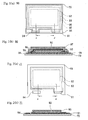
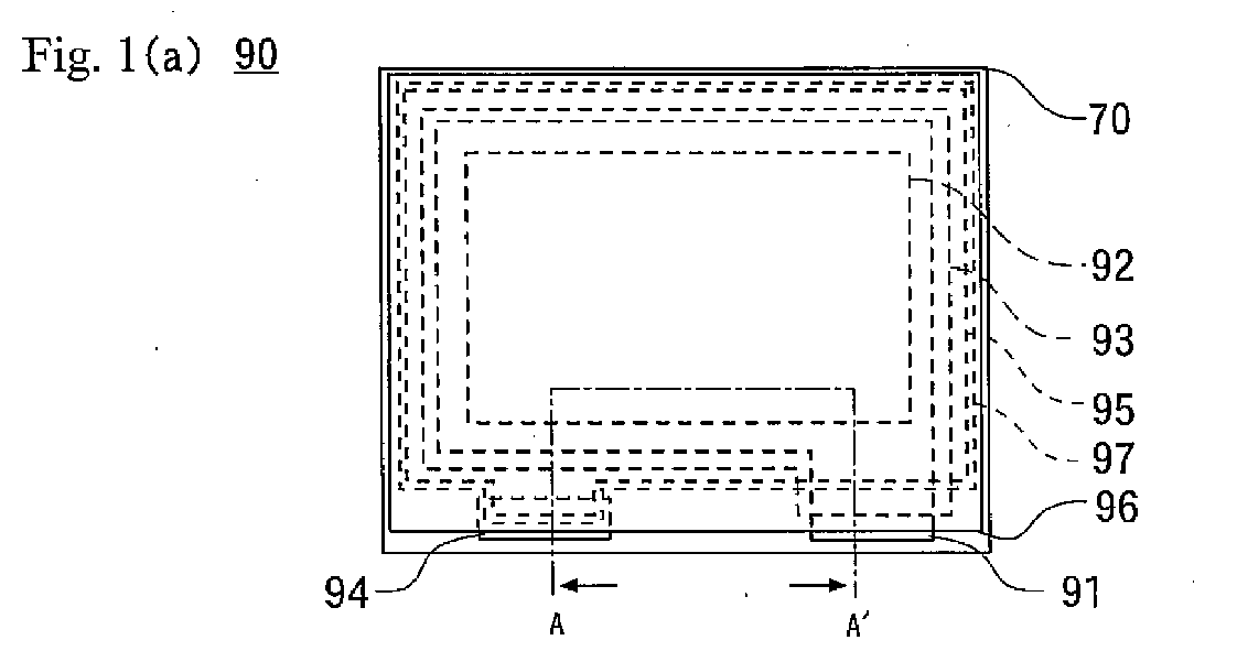
Fig. 1(a) is a plan view of a thin film lithium secondary battery; andFig. 1(b) is a sectional view of the thin film lithium secondary battery cut along a A-A' line shown inFig. 1(a) . -
Fig. 2(a) is a plan view of an object to be processed in which an electrolyte film is formed on its surface; andFig. 2(b) is a sectional view of the object to be processed cut along a B-B' line shown inFig. 2(a) , in which the electrolyte film is formed on the surface of the object to be processed. -
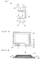
Fig. 3 shows a vapor deposition apparatus to be used in the present invention. -
Fig. 4(a) is a plan view of the object to be processed in which a negative electrode film is formed on its surface; andFig. 4(b) is a sectional view cut along a C-C' line shown inFig. 4(a) , of the object to be processed in which the negative electrode film is formed on the surface of the object to be processed. -
Fig. 5 shows a film-forming apparatus to be used in the present invention. -
Fig. 6(a) is a plan view of the object to be processed in which a film of lithium carbonate film is formed on its surface; andFig. 6(b) is a sectional view of the object to be processed cut along a D-D' line, shown inFig. 6(a) , in which the film of lithium carbonate is formed on the surface of the object to be processed. -
- 70
- substrate
- 71, 80, 81
- object to be processed
- 91
- positive pole electrical power collector film
- 92
- positive electrode film
- 93
- electrolyte film
- 94
- negative pole electrical power collector film
- 95
- negative electrode film
- 96
- protective film
- 97
- lithium carbonate film
- In
Fig. 1(a) , a reference numeral 90 generally illustrates a thin film lithium secondary battery shown in plan view, which is obtained by the production process of the present invention; andFig. 1(b) is the thin film lithium secondary battery, generally designated by reference numeral 90 and illustrated as a sectional view cut along with a line A-A' shown inFig. 1(a) . - The thin film lithium secondary battery 90 includes a
substrate 70, a positive pole electricalpower collector film 91, a negative pole electricalpower collector film 94, apositive electrode film 92, anegative electrode film 95, anelectrolyte film 93, and aprotective film 96. - The positive pole electrical
power collector film 91 and the negative pole electricalpower collector film 94 are arranged at places spaced on a surface of thesubstrate 70. - The
positive electrode film 92 is arranged on a surface of the positive pole electricalpower collector film 91; and theelectrolyte film 93 is arranged on a surface of thepositive electrode film 92. - The
negative electrode film 95 is arranged on a surface of theelectrolyte film 93; and thenegative electrode film 95 is in contact and electrically connected to the negative pole electricalpower collector film 94 in a state such that thenegative electrode film 95 is insulated from thepositive electrode film 92. - The
negative electrode film 95 has alithium carbonate film 97; and thelithium carbonate film 97 is formed on a surface and lateral faces of thenegative electrode film 95. - The
negative electrode film 95 is a metallic lithium film, and thelithium carbonate film 97 does not change the properties of the metallic lithium film to be discussed later. - The
protective film 96 is arranged on thelithium carbonate film 97 so that moisture is prevented from invading the layers under theprotective film 96. - Each of the positive pole electrical
power collector film 91 and the negative pole electricalpower collector film 94 are either one of an Al film, a Ti film and a Pt film in this specification; and the positive pole electricalpower collector film 91 and the negative pole electricalpower collector film 94 have only to be electrically conducting films. - The
electrolyte film 93 is an LiPON film, but may be a polymer film or a film of an inorganic compound, which includes lithium ions and has a structure for allowing the lithium ions to move. Here, theprotective film 96 is a resin film. - The
positive electrode film 92 includes lithium, and is, for example, an LiCo02 film, an LiNiO2 film, an LiMn2O4 film or the like. Thepositive electrode film 92 is the LiCoO2 film, but it may be a film having a structure, which allows the insertion of lithium and the release of the inserted lithium. - When the thin film lithium secondary battery 90 is to be charged, the negative pole electrical
power collector film 94 and the positive pole electricalpower collector film 91 are connected to an electric power source; and a negative voltage is applied to the negative pole electricalpower collector film 94; and a positive voltage is applied to the positive pole electricalpower collector film 91. Consequently, lithium in thepositive electrode film 92 is released from the inside of thepositive electrode film 92, and moved into theelectrolyte film 93 in the form of lithium ions, so that the amount of the lithium inside thepositive electrode film 92 decreases, and the lithium ions in theelectrolyte film 93 are converted to lithium and deposited on thenegative electrode film 95; then, a film of metallic lithium is formed on thenegative electrode film 95. - When the charged thin film lithium secondary battery 90 is to be discharged, the negative pole electrical
power collector film 94 and the positive pole electricalpower collector film 91 are connected via a conductive wire through a load in a state such that there is a potential difference between the negative pole electricalpower collector film 94 and the positive pole electricalpower collector film 91 so that the metallic lithium of thenegative electrode film 95 is converted to lithium ions, which are dissolved into theelectrolyte film 93, while lithium ions in theelectrolyte film 93 are inserted into thepositive electrode film 92 in the form of lithium; and consequently, electric current flows from the positive pole electricalpower collector film 91 to the negative pole electricalpower collector film 94 via the load. - As discussed above, the thin film lithium secondary battery 90 can perform charging and discharging.
- In the following detailed description, the formation of the
negative electrode film 92 and theprotective films 96 of the thin film lithium secondary battery 90 will be explained. - In
Fig. 2(a) , areference numeral 71 is a plan view of an object to be processed in a state whereby theelectrolyte film 93 has been arranged on the surface of thepositive electrode film 92, and the positive pole electricalpower collector film 91 and the negative pole electricalpower collector film 94 are arranged at places spaced on the surface of thesubstrate 70. Thepositive electrode film 92 and theelectrolyte film 93 are formed on the surface of the positive pole electricalpower collector film 91 in this order such that a part of the positive pole electricalpower collector film 91 and the surface of the negative pole electricalpower collector film 94 are exposed. In such a state, the surface of theelectrolyte film 93 is also exposed. - In
Fig. 2(b) ,reference numeral 71 generally illustrates the object to be processed 71 shown in sectional view cut along a B-B' line shown inFig. 2(a) . - In
Fig. 3 ,reference numeral 50 is a vapor deposition apparatus to be used in the present invention. Thevapor deposition apparatus 50 includes afirst vacuum chamber 51 and a loading/unloading chamber 52. - The
first vacuum chamber 51 and the loading/unloading chamber 52 are connected via agate valve 53. Here, atransfer device 54 is arranged inside the loading/unloading chamber 52, and the object to be processed is mounted on thetransfer device 54. When thegate valve 53 between the loading/unloading chamber 52 and thefirst vacuum chamber 51 is opened, the object to be processed can be carried from the loading/unloading chamber 52 into thefirst vacuum chamber 51, and carried out therefrom. - Vacuum evacuating
devices unloading chamber 52 and thefirst vacuum chamber 51; and when thevacuum evacuating devices unloading chamber 52 and thefirst vacuum chamber 51 can be set to a vacuum ambience. Agas introducing device 57 is connected to the loading/unloading chamber 52. Thegas introducing device 57 includes a cylinder (not shown) in which a surface-treating gas is stored; and the surface-treating gas can be introduced into the loading/unloading chamber 52. Here, the surface-treating gas is a mixed gas of an argon gas and carbon dioxide. - A
substrate holder 59 is arranged at a ceiling inside thefirst vacuum chamber 51; and avapor deposition source 49 in which metallic lithium is arranged is placed on a bottom face. Thevacuum deposition source 49 is provided with aheater 48. When the inside offirst vacuum chamber 51 is set to the vacuum ambience and thevapor deposition source 49 is heated inside thefirst vacuum chamber 51 by turning on the power source of theheater 48, a vapor of the metallic lithium is discharged from thevapor deposition source 49. - The
gate valve 53 between the loading/unloading chamber 52 and thefirst vacuum chamber 51 is closed, thevacuum evacuating device 56 connected to thefirst vacuum chamber 51 is operated, and the inside of thefirst vacuum chamber 51 is vacuum evacuated. - An
inlet door 58 provided in the loading/unloading chamber 52 is opened; the object to be processed 71 is carried into the loading/unloading chamber 52 from the atmosphere or a dried atmosphere; and theinlet door 58 is closed. - After the
vacuum evacuating device 55 connected to the loading/unloading chamber 52 is operated and a vacuum ambience is formed by vacuum evacuating the loading/unloading chamber 52, thegate valve 53 between the loading/unloading chamber 52 and thefirst vacuum chamber 51 is opened, and the object to be processed 71 is carried into thefirst vacuum chamber 51 from the loading/unloading chamber 52 in such a state where the vacuum ambience is maintained. - The object to be processed 71 is held by the
substrate holder 59 in a state such that the face where theelectrolyte film 93 and the negative pole electricalpower collector film 94 are arranged is directed to thevapor deposition source 49. - A
mask 76 having anopening 77 is arranged at a surface of the object to be processed 71 inside thevacuum chamber 51, so that the periphery of the object to be processed 71 is covered, and the surface of theelectrolyte film 93 of the object to be processed 71, a Vicinity area thereof and a part of the negative pole electricalpower collector film 94 are exposed to a bottom face of theopening 77. In this state, when the metallic lithium inside thevacuum source 49 is evaporated and a vapor of the metallic lithium is discharged into thevacuum chamber 51, the vapor reaches the surface of the object to be processed 71 through theopening 77 of themask 76, so that anegative electrode film 95 made of a film of the metallic lithium is formed, thenegative electrode film 95 covering the surface and the lateral face of theelectrolyte film 93. - The
electrolyte film 93 is arranged between thenegative electrode film 95 and thepositive electrode film 92; and thenegative electrode film 95 and thepositive electrode film 92 are not in contact with each other, but are insulated. - Moreover, the
negative electrode film 95 is also formed on the exposed surface of the negative pole electricalpower collecting film 94; thenegative electrode film 95 is in contact with the negative pole electricalpower collecting film 94; and this portion of thenegative electrode film 95 is connected to thenegative electrode film 95 on theelectrolyte film 93. Therefore, the portion of thenegative electrode film 95, which is on theelectrolyte film 93, is electrically connected to the negative pole electricalpower collector film 94. - After the
negative electrode film 95 made of the metallic lithium film having a predetermined film thickness is formed, the heating of thevapor deposition source 49 is stopped to terminate the vapor deposition. - The object to be processed 71 shown in
Figs. 2(a) and 2(b) is converted to the object to be processed 80 shown inFigs. 4(a) and 4(b) through the formation of thenegative electrode film 95 on the surface of theelectrolyte film 93.Fig. 4(a) is a plan view of the object to be processed 80; andFig. 4(b) is a sectional view of the object to be processed 80 cut along a C-C' line shown inFig. 4(a) . - The inside of the loading/
unloading chamber 52 has been vacuum evacuated by thevacuum evacuating device 55; and the vacuum ambience is formed therein. After thegate valve 53 between the loading/unloading chamber 52 and thefirst vacuum chamber 51 is opened, the object to be processed 71 is carried into the loading/unloading chamber 52 and thegate valve 53 between the loading/unloading chamber 52 and thefirst vacuum chamber 51 is closed, the vacuum evacuation of the loading/unloading chamber 52 is stopped, the surface-treating gas is introduced into the loading/unloading chamber 52 in the vacuum ambience by operating thegas introduction device 55 connected to the loading/unloading chamber 52. The surface-treating gas is introduced until the pressure inside the loading/unloading chamber 52 reaches the atmospheric pressure. - The exposed surface of the
negative electrode film 95 of the object to be processed 80 is in contact with the surface-treating gas without being in contact with the atmosphere containing moisture; and the metallic lithium located at the exposed surface of thenegative electrode film 95 reacts with carbon dioxide in the surface-treating gas, so that lithium carbonate is produced to form thelithium carbonate film 97 on the surface and the lateral face of thenegative electrode film 95 made of the metallic lithium film (Fig. 6 ). In such a state, the surface of thelithium carbonate film 97 is exposed. - Since the
lithium carbonate film 97 does not allow the penetration of moisture or oxygen, the moisture or oxygen does not reach thenegative electrode film 95 under thelithium carbonate film 97. - Carbon dioxide is contained in the surface-treating gas at a content corresponding to 0.01% or more to 4% or less of a total pressure, assuming that the total pressure is the pressure of the treating gas.
- After the
lithium carbonate film 97 is formed, the object to be processed 81 is carried into a glovebox filled with an argon gas containing no moisture, without being exposed to the atmosphere, and taken out by opening thedoor 58. - Although the
lithium carbonate film 97 is formed inside the loading/unloading chamber 52, the object to be processed 80 can also be formed with thenegative electrode film 95 being carried into the glovebox filled with the treating gas, without being exposed to the atmosphere; and thelithium carbonate film 97 may be formed inside the glovebox. - As explained above, according to the present invention, since the
lithium carbonate film 97 is formed on the surface of thenegative electrode film 95 made of the metallic lithium film, the moisture gas does not penetrate into the metallic lithium film under thelithium carbonate film 97. Since no hydroxide film is formed in the metallic lithium film, the properties of the metallic lithium film do not change. - Although the metallic lithium film causes a color change reaction through a composite reaction of oxidation and hydroxylation, no composite reaction takes place and thus no color change occurs in the metallic lithium film even through it is in contact with a very small amount of oxygen gas or the moisture gas after the
lithium carbonate film 97 is provided. - Meanwhile, no moisture is contained in the above surface-treating gas. Even if moisture is contained in the surface-treating gas, metallic lithium is more likely to become a carbonate than a hydroxide and an oxide, so that the
lithium carbonate film 97 is formed before the hydroxide film is formed on the surface of the metallic lithium film. Therefore, even if gaseous water is contained in the surface-treating gas, the properties of the metallic lithium film are not changed with the contained moisture. - Although the surface-treating gas is a mixed gas of the argon gas and carbon dioxide, a mixed gas of a rare gas other than argon and carbon dioxide may be used. On the other hand, a mixed gas of an N2 gas and carbon dioxide may also be used. In summary, a surface-treating gas containing a diluent gas that does not react with metallic lithium (such as, a gas containing either one or both of the rare gas and the N2 gas) and carbon dioxide gas can be used. The formed metallic lithium film is brought into contact with the surface-treating gas, before the formation of lithium hydroxide and lithium oxide, without being exposed to the atmosphere.
- A
carrier box 65 is arranged inside the glovebox; the obj ect to be processed 81 formed with thelithium carbonate film 97 is placed inside thecarrier box 65 filled with the above diluent gas or the above surface-treating gas; thecarrier box 65 is gas-tightly sealed; and the object to be processed is carried out from the glovebox and carried into the film forming apparatus in a state such that no atmosphere enters inside thecarrier box 65. When the vacuum ambience is formed in the loading/unloading chamber 52, the object to be processed 81 is placed in thecarrier box 65 inside the loading/unloading chamber 52; and then, the surface-treating gas is introduced into the loading/unloading chamber 52 and alithium carbonate film 97 is formed on the surface of the object to be processed 81 inside thecarrier box 65. - In
Fig. 3 , areference numeral 30 is a film forming apparatus, and thefilm forming apparatus 30 includes asecond vacuum chamber 31. Avacuum evacuating device 35 is connected to thesecond vacuum chamber 31; and when thevacuum evacuating device 35 is operated, a vacuum ambience can be formed inside thesecond vacuum chamber 31 though vacuum evacuation. Asubstrate holder 32 is arranged at a ceiling of thesecond vacuum chamber 31, and first andsecond vessels second vacuum chamber 31. - The first and
second vessels second heaters second vessels second vessels second heaters - The object to be processed 81 formed with the
lithium carbonate film 97 is carried into thesecond vacuum chamber 31 from aninlet door 36 via a glovebox (not shown) and a carry-in chamber (not shown), without being exposed to the atmosphere. - The inside of the
second vacuum chamber 31 is made to the vacuum ambience by thevacuum evacuating device 35; and the object to be processed 81 is held by asubstrate holder 32 in such a manner that an exposed surface of the lithium carbonate film 99 of the object to be processed 81 is opposed to the first andsecond vessels - Here, a diamine compound (such as, 1, 12-diaminododecane) is placed in the
first vessel 33; an isocyanate compound (such as, 1, 3-bis (methyl isocyanate) cyclohexane) is placed in thesecond vessel 34; their respective vapors are generated; and aprotective film 96 made of a polyurea film is formed on the exposed surface of thelithium carbonate film 97 by separately bringing and reacting the vapors on the exposed surface of thelithium carbonate film 97. The exposed surface and lateral face of thelithium carbonate film 97 are covered with theprotective film 96. - After the
protective film 96 made of the polyurea film is formed in a predetermined film thickness, the powers of the first andsecond heaters Figs. 1(a) and (b) through the formation of theprotective film 96 on thelithium carbonate film 97. The thin film lithium secondary battery 90 is taken out into the atmosphere from thesecond vacuum chamber 31. - In this embodiment, although the
protective film 96 made of the polyurea film is formed by the vapor deposition polymerization reaction, aprotective film 96 made of an Si02 film or an SiN film may be formed by a sputtering method. Theprotective film 96 may be any film, so long as it prevents moisture in the atmosphere from invading the films formed under theprotective film 96. - Meanwhile, portions of the positive pole electrical
power collector film 91 and the negative pole electricalpower collector film 94 protrude and are exposed from theprotective film 96, so that those portions can be connected to an external circuit.
Claims (6)
- A process for producing a chargeable-and-dischargeable thin film lithium secondary battery, which comprises:a substrate;a positive electrode film arranged on the substrate and formed in a structure of which lithium is insertable and releasable,an electrolyte film which is arranged on the positive electrode film and being in contact with the positive electrode film, and contains lithium ions and in which lithium ions are movable, anda negative electrode film made of metallic lithium and arranged on the electrolyte film and being in contact with the electrolyte film,the process, comprising the steps of:after the negative electrode film is formed, forming a film of lithium carbonate on a surface of the negative electrode film by bringing a surface of the negative electrode film into contact with a surface-treating gas containing a diluent gas not reactable with metallic lithium and carbon dioxide without exposing the negative electrode film to the atmosphere.
- The process for producing the thin film lithium secondary battery according to claim 1, wherein after the film of lithium carbonate is formed, the substrate is placed in a carrier box which is filled with one of the diluent gas and the surface-treating gas, and wherein the carrier box in this state is moved in the atmosphere.
- The process for producing the thin film lithium secondary battery according to claim 1, wherein after the film of lithium carbonate is formed, a protective film is formed on the film of lithium carbonate.
- The process for producing the thin film lithium secondary battery according to claim 1, wherein the carbon dioxide is contained in the surface-treating gas at a partial pressure of at least 0.01% and at most 4%.
- A chargeable-and-dischargeable thin film lithium secondary battery, comprising:a substrate;a positive electrode film arranged on the substrate and formed in a structure of which lithium is insertable and releasable;an electrolyte film which is arranged on the positive electrode film and in contact with the positive electrode film and contains lithium ions and in which lithium ions are movable; anda negative electrode film made of metallic lithium and arranged on the electrolyte film and in contact with the electrolyte film,wherein a film of lithium carbonate is arranged on the negative electrode film and in contact with the negative electrode film.
- The thin film lithium secondary battery according to claim 5, wherein the film of lithium carbonate is formed on a surface and a lateral face of the negative electrode film.
Applications Claiming Priority (2)
| Application Number | Priority Date | Filing Date | Title |
|---|---|---|---|
| JP2009186161 | 2009-08-10 | ||
| PCT/JP2010/063314 WO2011018980A1 (en) | 2009-08-10 | 2010-08-05 | Process for production of thin film lithium secondary battery |
Publications (2)
| Publication Number | Publication Date |
|---|---|
| EP2475042A1 true EP2475042A1 (en) | 2012-07-11 |
| EP2475042A4 EP2475042A4 (en) | 2014-01-22 |
Family
ID=43586158
Family Applications (1)
| Application Number | Title | Priority Date | Filing Date |
|---|---|---|---|
| EP10808163.9A Withdrawn EP2475042A4 (en) | 2009-08-10 | 2010-08-05 | Process for production of thin film lithium secondary battery |
Country Status (5)
| Country | Link |
|---|---|
| US (1) | US20120196175A1 (en) |
| EP (1) | EP2475042A4 (en) |
| JP (1) | JP5461561B2 (en) |
| KR (1) | KR101385393B1 (en) |
| WO (1) | WO2011018980A1 (en) |
Cited By (2)
| Publication number | Priority date | Publication date | Assignee | Title |
|---|---|---|---|---|
| EP2879225A1 (en) * | 2013-11-28 | 2015-06-03 | GS Yuasa International Ltd. | Electric storage device and electric storage apparatus |
| CN110352264A (en) * | 2018-02-07 | 2019-10-18 | 株式会社爱发科 | Thin film forming method, thin film forming device, and lithium battery |
Families Citing this family (8)
| Publication number | Priority date | Publication date | Assignee | Title |
|---|---|---|---|---|
| JP6015307B2 (en) * | 2012-09-28 | 2016-10-26 | 富士通株式会社 | All solid state secondary battery |
| WO2015152176A1 (en) * | 2014-03-31 | 2015-10-08 | 独立行政法人物質・材料研究機構 | Nano-coating material, method for manufacturing same, coating agent, functional material, and method for manufacturing same |
| DE112017003085T5 (en) * | 2016-06-21 | 2019-03-14 | Applied Materials, Inc. | Interfacial layer for improved lithium metal cyclization |
| WO2018193993A1 (en) * | 2017-04-19 | 2018-10-25 | 株式会社アルバック | Film forming apparatus and film forming method |
| KR102140128B1 (en) * | 2017-06-20 | 2020-07-31 | 주식회사 엘지화학 | Lithium Metal Electrode and Lithium Secondary Battery Comprising the Same |
| WO2023189710A1 (en) * | 2022-03-31 | 2023-10-05 | 株式会社村田製作所 | Negative electrode and method of producing same, and battery |
| JP7905204B2 (en) * | 2022-04-28 | 2026-08-14 | 日産自動車株式会社 | All solid state battery |
| WO2025034742A1 (en) * | 2023-08-08 | 2025-02-13 | Applied Materials, Inc. | Uv enhanced c02 passivation of lithium anode |
Family Cites Families (9)
| Publication number | Priority date | Publication date | Assignee | Title |
|---|---|---|---|---|
| JPS56103982A (en) * | 1979-12-29 | 1981-08-19 | Sankyo Seiki Mfg Co Ltd | Speed control device for small dc motor |
| FR2581483B1 (en) * | 1985-05-03 | 1990-07-13 | Balkanski Minko | INTEGRATED SOLID CELL AND METHOD FOR PRODUCING THE SAME |
| JP3578015B2 (en) * | 1998-12-03 | 2004-10-20 | 住友電気工業株式会社 | Lithium secondary battery |
| JP2001076710A (en) * | 1999-09-07 | 2001-03-23 | Matsushita Electric Ind Co Ltd | Secondary battery and electric circuit board using the same |
| JP3412616B2 (en) * | 2000-07-19 | 2003-06-03 | 住友電気工業株式会社 | Method for producing negative electrode for lithium secondary battery |
| US6780542B2 (en) * | 2001-09-13 | 2004-08-24 | Wilson Greatbatch Ltd. | Lithium oxyhalide cell with improved safety and voltage delay characteristics |
| EP1313158A3 (en) | 2001-11-20 | 2004-09-08 | Canon Kabushiki Kaisha | Electrode material for rechargeable lithium battery, electrode comprising said electrode material, rechargeable lithium battery having said electrode , and process for the production thereof |
| US6911280B1 (en) * | 2001-12-21 | 2005-06-28 | Polyplus Battery Company | Chemical protection of a lithium surface |
| JP4442235B2 (en) * | 2004-01-28 | 2010-03-31 | ソニー株式会社 | Negative electrode for secondary battery, secondary battery, and production method thereof |
-
2010
- 2010-08-05 WO PCT/JP2010/063314 patent/WO2011018980A1/en not_active Ceased
- 2010-08-05 JP JP2011526724A patent/JP5461561B2/en active Active
- 2010-08-05 EP EP10808163.9A patent/EP2475042A4/en not_active Withdrawn
- 2010-08-05 KR KR1020127003682A patent/KR101385393B1/en active Active
-
2012
- 2012-02-07 US US13/367,576 patent/US20120196175A1/en not_active Abandoned
Cited By (6)
| Publication number | Priority date | Publication date | Assignee | Title |
|---|---|---|---|---|
| EP2879225A1 (en) * | 2013-11-28 | 2015-06-03 | GS Yuasa International Ltd. | Electric storage device and electric storage apparatus |
| CN104681803A (en) * | 2013-11-28 | 2015-06-03 | 株式会社杰士汤浅国际 | Electric storage device and electric storage apparatus |
| US9350049B2 (en) | 2013-11-28 | 2016-05-24 | Gs Yuasa International Ltd. | Electric storage device and electric storage apparatus |
| CN104681803B (en) * | 2013-11-28 | 2018-01-16 | 株式会社杰士汤浅国际 | Charge storage element and electrical storage device |
| CN110352264A (en) * | 2018-02-07 | 2019-10-18 | 株式会社爱发科 | Thin film forming method, thin film forming device, and lithium battery |
| EP3553203A4 (en) * | 2018-02-07 | 2020-12-09 | Ulvac Inc | THIN FILM MOLDING METHOD, THIN FILM FORMING DEVICE, AND LITHIUM BATTERY |
Also Published As
| Publication number | Publication date |
|---|---|
| JP5461561B2 (en) | 2014-04-02 |
| WO2011018980A1 (en) | 2011-02-17 |
| US20120196175A1 (en) | 2012-08-02 |
| EP2475042A4 (en) | 2014-01-22 |
| KR20120042965A (en) | 2012-05-03 |
| KR101385393B1 (en) | 2014-04-14 |
| JPWO2011018980A1 (en) | 2013-01-17 |
Similar Documents
| Publication | Publication Date | Title |
|---|---|---|
| US20120196175A1 (en) | Process for producing thin film lithium secondary battery | |
| JP7599454B2 (en) | Li-ion battery without olefin separator | |
| CN106207162B (en) | All-solid-state lithium-ion secondary battery and method for producing the same | |
| JP5342918B2 (en) | Thin film lithium ion secondary battery, thin film lithium ion secondary battery manufacturing method | |
| JP2023507160A (en) | lithium metal electrode | |
| EP3553203B1 (en) | Thin film formation method and thin film formation device | |
| Jung et al. | Understanding abnormal potential behaviors at the 1st charge in Li2S cathode material for rechargeable Li–S batteries | |
| US9356320B2 (en) | Lithium battery having low leakage anode | |
| KR20180123369A (en) | A cathode material of an all-solid state battery comprising a coating layer for preventing diffusion and a method for preparing thereof | |
| JP2013512547A (en) | Lithium ion battery and method for producing lithium ion battery | |
| JP2011108603A (en) | Thin film lithium secondary battery, and forming method of thin film lithium secondary battery | |
| US20190006697A1 (en) | Method for producing a battery cell | |
| EP4210130A1 (en) | Positive-electrode active material for lithium secondary battery, positive electrode for lithium secondary battery, and lithium secondary battery | |
| JP2022528786A (en) | Lithium metal anode assembly and equipment and manufacturing method thereof | |
| CN106784988A (en) | A kind of flexible all solid-state thin-film lithium battery and its production method | |
| CN105556719A (en) | Method for producing electrochemical cells of a solid-state battery | |
| CN109148826B (en) | Negative electrode, preparation method thereof and lithium battery | |
| US12525639B2 (en) | Stabilizing garnet-type solid-state electrolytes through atomic layer deposition of ultra-thin layered materials and methods of making same | |
| KR102322343B1 (en) | Thin film encapsulation for all solid-state batteries and method for fabricating the same | |
| JP7646334B2 (en) | Active material particles | |
| JP4174729B2 (en) | Method for forming inorganic solid electrolyte | |
| US11329339B2 (en) | Method for manufacturing a battery cell with an oxygen diffusion barrier layer | |
| CN114899480A (en) | A kind of doped sulfide solid electrolyte and preparation method and application thereof | |
| JP2009128203A (en) | Method for analyzing lithium | |
| KR20220065410A (en) | Lithium electrode manufacturing method |
Legal Events
| Date | Code | Title | Description |
|---|---|---|---|
| PUAI | Public reference made under article 153(3) epc to a published international application that has entered the european phase |
Free format text: ORIGINAL CODE: 0009012 |
|
| 17P | Request for examination filed |
Effective date: 20120210 |
|
| AK | Designated contracting states |
Kind code of ref document: A1 Designated state(s): AL AT BE BG CH CY CZ DE DK EE ES FI FR GB GR HR HU IE IS IT LI LT LU LV MC MK MT NL NO PL PT RO SE SI SK SM TR |
|
| DAX | Request for extension of the european patent (deleted) | ||
| A4 | Supplementary search report drawn up and despatched |
Effective date: 20140107 |
|
| RIC1 | Information provided on ipc code assigned before grant |
Ipc: H01M 4/134 20100101ALI20131219BHEP Ipc: H01M 4/62 20060101ALI20131219BHEP Ipc: H01M 4/04 20060101ALI20131219BHEP Ipc: H01M 10/052 20100101ALI20131219BHEP Ipc: H01M 4/1395 20100101ALI20131219BHEP Ipc: H01M 10/058 20100101AFI20131219BHEP |
|
| STAA | Information on the status of an ep patent application or granted ep patent |
Free format text: STATUS: THE APPLICATION IS DEEMED TO BE WITHDRAWN |
|
| 18D | Application deemed to be withdrawn |
Effective date: 20140805 |