EP2474878A1 - Electronic device having an electronic compass adapted to detect when the device is in a holster - Google Patents
Electronic device having an electronic compass adapted to detect when the device is in a holster Download PDFInfo
- Publication number
- EP2474878A1 EP2474878A1 EP11150218A EP11150218A EP2474878A1 EP 2474878 A1 EP2474878 A1 EP 2474878A1 EP 11150218 A EP11150218 A EP 11150218A EP 11150218 A EP11150218 A EP 11150218A EP 2474878 A1 EP2474878 A1 EP 2474878A1
- Authority
- EP
- European Patent Office
- Prior art keywords
- electronic device
- portable electronic
- holster
- pattern
- orientation
- Prior art date
- Legal status (The legal status is an assumption and is not a legal conclusion. Google has not performed a legal analysis and makes no representation as to the accuracy of the status listed.)
- Granted
Links
Images





Classifications
-
- G—PHYSICS
- G06—COMPUTING OR CALCULATING; COUNTING
- G06F—ELECTRIC DIGITAL DATA PROCESSING
- G06F1/00—Details not covered by groups G06F3/00 - G06F13/00 and G06F21/00
- G06F1/16—Constructional details or arrangements
- G06F1/1613—Constructional details or arrangements for portable computers
- G06F1/1626—Constructional details or arrangements for portable computers with a single-body enclosure integrating a flat display, e.g. Personal Digital Assistants [PDAs]
-
- H—ELECTRICITY
- H04—ELECTRIC COMMUNICATION TECHNIQUE
- H04B—TRANSMISSION
- H04B1/00—Details of transmission systems, not covered by a single one of groups H04B3/00 - H04B13/00; Details of transmission systems not characterised by the medium used for transmission
- H04B1/38—Transceivers, i.e. devices in which transmitter and receiver form a structural unit and in which at least one part is used for functions of transmitting and receiving
- H04B1/3827—Portable transceivers
- H04B1/3877—Arrangements for enabling portable transceivers to be used in a fixed position, e.g. cradles or boosters
-
- H—ELECTRICITY
- H04—ELECTRIC COMMUNICATION TECHNIQUE
- H04B—TRANSMISSION
- H04B1/00—Details of transmission systems, not covered by a single one of groups H04B3/00 - H04B13/00; Details of transmission systems not characterised by the medium used for transmission
- H04B1/38—Transceivers, i.e. devices in which transmitter and receiver form a structural unit and in which at least one part is used for functions of transmitting and receiving
- H04B1/3827—Portable transceivers
- H04B1/3888—Arrangements for carrying or protecting transceivers
-
- H—ELECTRICITY
- H04—ELECTRIC COMMUNICATION TECHNIQUE
- H04M—TELEPHONIC COMMUNICATION
- H04M1/00—Substation equipment, e.g. for use by subscribers
- H04M1/02—Constructional features of telephone sets
- H04M1/04—Supports for telephone transmitters or receivers
-
- H—ELECTRICITY
- H04—ELECTRIC COMMUNICATION TECHNIQUE
- H04M—TELEPHONIC COMMUNICATION
- H04M2250/00—Details of telephonic subscriber devices
- H04M2250/16—Details of telephonic subscriber devices including more than one display unit
-
- H—ELECTRICITY
- H04—ELECTRIC COMMUNICATION TECHNIQUE
- H04W—WIRELESS COMMUNICATION NETWORKS
- H04W52/00—Power management, e.g. Transmission Power Control [TPC] or power classes
- H04W52/02—Power saving arrangements
- H04W52/0209—Power saving arrangements in terminal devices
- H04W52/0251—Power saving arrangements in terminal devices using monitoring of local events, e.g. events related to user activity
-
- Y—GENERAL TAGGING OF NEW TECHNOLOGICAL DEVELOPMENTS; GENERAL TAGGING OF CROSS-SECTIONAL TECHNOLOGIES SPANNING OVER SEVERAL SECTIONS OF THE IPC; TECHNICAL SUBJECTS COVERED BY FORMER USPC CROSS-REFERENCE ART COLLECTIONS [XRACs] AND DIGESTS
- Y02—TECHNOLOGIES OR APPLICATIONS FOR MITIGATION OR ADAPTATION AGAINST CLIMATE CHANGE
- Y02D—CLIMATE CHANGE MITIGATION TECHNOLOGIES IN INFORMATION AND COMMUNICATION TECHNOLOGIES [ICT], I.E. INFORMATION AND COMMUNICATION TECHNOLOGIES AIMING AT THE REDUCTION OF THEIR OWN ENERGY USE
- Y02D30/00—Reducing energy consumption in communication networks
- Y02D30/70—Reducing energy consumption in communication networks in wireless communication networks
Definitions
- Embodiments herein relate generally to portable electronic devices, and in particular to portable electronic devices having an electronic compass adapted to detect when the device is received in a holster.
- Portable electronic devices including portable electronic devices, have gained widespread use and may provide a variety of functions including, for example, telephonic, electronic text messaging and other personal information manager (PIM) application functions.
- Portable electronic devices can include several types of devices including for example cellular phones, smart phones, Personal Digital Assistants (PDAs), tablets and laptop computers.
- PDAs Personal Digital Assistants
- Devices such as PDAs or smart phones are generally intended for handheld use and ease of portability, and smaller devices may be generally desirable for portability and for use with a user's hands.
- portable electronic devices may be touch sensitive devices.
- some devices may include a display (e.g. a liquid crystal display (LCD)) with a touch-sensitive overlay and may be particularly useful where limited space is available for user input and output devices.
- LCD liquid crystal display
- portable electronic devices may include a keypad having a plurality of keys and one or more other function buttons in addition to a display. Other devices may not have a keypad.
- Figure 1 is a simplified block diagram of components of a portable electronic device according to one embodiment
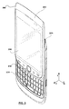
- Figure 2 is a first perspective view of a portable electronic device according to one embodiment shown in a closed position
- Figure 3 is a second perspective view of the portable electronic device of Figure 2 shown in an open position
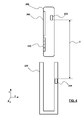
- Figure 4 is a schematic side view of a portable electronic device and a holster with the device out of the holster;
- Figure 5 is a schematic side view of the portable electronic device and the holster of Figure 4 with the portable electronic device received in the holster in a first orientation;
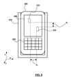
- Figure 6 is a schematic front view of the portable electronic device and the holster of Figure 5 ;
- Figure 7 is a schematic side view of the portable electronic device and the holster of Figure 4 with the portable electronic device received in the holster in a second orientation;
- Figure 8 is a schematic side view of the portable electronic device and the holster of Figure 4 with the portable electronic device received in the holster in a third orientation;
- Figure 9 is a flowchart of a method of detecting when a portable electronic device is in a holster.
- FIG. 1 shows a simplified block diagram of components of a portable electronic device 100 according to one embodiment.
- the portable electronic device 100 includes multiple components, including for example a processor 102 that controls the operations of the portable electronic device 100.
- Communication functions including data communications, voice communications, or both may be performed through a communication subsystem 104.
- data received by the portable electronic device 100 may be decompressed and decrypted by a decoder 106.
- the portable electronic device 100 may be a battery-powered device and as shown may include a battery interface 142 for receiving one or more batteries 144.
- the communication subsystem 104 may receive messages from and send messages to a wireless network 150.
- the wireless network 150 may be any type of wireless network, including, but not limited to, data-centric wireless networks, voice-centric wireless networks, and dual-mode networks that support both voice and data communications.
- the processor 102 generally interacts with subsystem components such as a Random Access Memory (RAM) 108, a flash memory 110, and a display 112 (which may have a touch-sensitive overlay 114 connected to an electronic controller 116 that together comprise a touch-sensitive display 118, also be referred to as a touchscreen display).
- Information such as text, characters, symbols, images, icons, and other items may be displayed on the touch-sensitive display 118.
- user-interaction with the graphical user interface may be performed through the touch-sensitive overlay 114.
- the processor 102 may interact with the touch-sensitive overlay 114 via the electronic controller 116.
- actuator assembly 120 could include an actuator assembly 120, one or more optional force sensors 122, an auxiliary input/output (I/O) subsystem 124, a data port 126, one or more speakers 128, a microphone 130, a short-range communications module 132 and other device subsystems 134.
- I/O auxiliary input/output
- the processor 102 may also interact with an accelerometer 136 as shown in Figure 1 .
- the accelerometer 136 may be used for detecting direction of gravitational forces or gravity-induced reaction forces.
- the portable electronic device 100 may use a Subscriber Identity Module or a Removable User Identity Module (SIM/RUIM) card 138 inserted into a SIM/RUIM interface 140 for communication with a network, such as the wireless network 150.
- SIM/RUIM Removable User Identity Module
- user identification information may be programmed into the flash memory 110, or via other techniques.
- the portable electronic device 100 also generally includes an operating system 146 and software components 148 that are executed by the processor 102.
- the operating system 146 and software components 148 may be stored in a persistent store such as the flash memory 110 or another data storage device. Additional applications may be loaded onto the portable electronic device 100 through the wireless network 150, the auxiliary I/O subsystem 124, the data port 126, the short-range communications subsystem 132, or any other suitable device subsystem 134.
- a received signal such as a text message, an e-mail message, or web page download may be processed by the communication subsystem 104 and input to the processor 102.
- the processor 102 may then process the received signal for output to the display 112 or alternatively to the auxiliary I/O subsystem 124.
- a user may compose data items, such as e-mail messages, for example, which may be transmitted over the wireless network 150 through the communication subsystem 104.
- the overall operation of the portable electronic device 100 may be similar.
- the speaker 128 may output audible information converted from electrical signals
- the microphone 130 may convert audible information into electrical signals for processing.
- the portable electronic device also includes an electronic compass 152.
- the electronic compass 152 may facilitate location and direction based services, such as navigation, by sensing the position of the portable electronic device 100 in relation to one or more magnetic fields, particularly the Earth's magnetic field.
- the electronic compass 152 may include a magnetometer.
- the magnetometer may include a multi-axis magneto-impedance sensor (e.g. a three-axis magneto-impedance sensor) or another suitable sensor.
- the electronic compass 152 may include three magneto-impedance (MI) sensors within a single integrated circuit package, each MI sensor operable to detect a magnetic field along a particular axis.
- the portable electronic device 100 can use signals from the MI sensors to determine direction or location information (or both) for the portable electronic device 100, which may be useful for navigating using the portable electronic device 100 for example.
- MI magneto-impedance
- magnetic fields may be measured along each of three orthogonal axes (e.g. x-axis, y-axis and z-axis as shown in Figure 2 ). Accordingly, the position and direction of the portable electronic device 100 with respect to the Earth's magnetic field can be determined to a generally desired degree of accuracy, depending on the characteristics of the electronic compass 152.
- suitable three-axis magneto impedance sensors for the electronic compass 152 include sensors from Aichi Micro Intelligent Corporation, such as the AMI304 and AMI306 sensors.
- the portable electronic device 200 is a "slider" or “sliding” device that includes an upper housing 202 (sliding portion) and a lower housing 204 (base portion).
- the upper housing 202 and lower housing 204 are coupled together and are slidable between a closed position (as shown in Figure 2 ) and an open position (e.g. as shown in Figure 3 ) generally along a direction aligned with the x-axis.
- the upper housing 202 in this embodiment includes a display 206, which could be an LCD, which may have touch screen capabilities (and which could be the touch screen display 118 identified in Figure 1 ).
- a display 206 which could be an LCD, which may have touch screen capabilities (and which could be the touch screen display 118 identified in Figure 1 ).
- the upper housing 202 and lower housing 204 may include one or more input apparatus, such as navigation keys or buttons, a physical or virtual keyboard, a trackpad, trackball, multimedia keys, and the like.
- the upper housing 202 in this embodiment includes an auxiliary input device 212.
- the auxiliary input device 212 may be an optical navigation module (e.g. a trackpad or optical joystick) that responds to user interaction, and which may be used for navigating around the display screen 206, to select objects on the display screen 206, or for other purposes.
- the auxiliary input device 212 may be a mechanical device that responds to user interaction (e.g. a trackball).
- the display 206 and the auxiliary input device 212 are generally disposed on a front of the upper housing 202 and may be exposed for user accessibility when the portable electronic device 200 is in both the open or closed position.
- the upper housing 202 may also include other input devices, such as a dedicated phone application button, a "disconnect call” button, a home screen button, and the like. In various embodiments, these input devices may include optical sensors, mechanical buttons, or both.
- the portable electronic device 200 may include a keypad 220 in addition to a display 206.
- the keypad 220 is provided on the lower housing 204.
- the keypad 220 generally includes a plurality of alphanumeric keys, which may be positioned in a plurality of rows and columns.
- the keys may represent an alphabet and may be arranged in a standard keyboard layout (e.g. QWERTY, QWERTZ, DVORAK, etc.).
- the keypad 220 may be positioned below the display 206.
- the portable electronic device 200 is sized and shaped so as to receivable within a holster 230.
- the holster 230 may be useful for carrying or protecting the device 200.
- the portable electronic device 200 may be placed in the holster 230 when the portable electronic device 200 is not in use, or when the portable electronic device 200 is being used with a headset or headphones.
- the holster 230 may help prevent accidental key-presses of the keypad 220 or the display 206 (or both) when not desired.
- the holster 230 could be worn on a belt, carried by a user (e.g. in a bag or purse or in their hand), could be adapted to be mounted in a car or another vehicle (e.g. so the portable electronic device 100 can be used as a navigation aid while driving), and so on.
- the portable electronic device 200 includes an electronic compass 232, which could be the same as or similar to the electronic compass 152.
- the electronic compass 232 could include a three-axis magneto-impedance sensor or another magnetometer, and which could be adapted to measure magnetic fields along three axes.
- the electronic compass 232 may be used for navigational purposes, such as for determining location or direction information (or both) for the portable electronic device 200.
- the electronic compass 232 is also adapted to detect whether the portable electronic device 200 is located within the holster 230.
- the electronic compass is positioned to cooperate with a magnetic element 234 located in the holster 230 to determine whether the device 200 is in (or out) of the holster 230 according to measured magnetic field patterns.
- the magnetic element 234 could be a magnet or another object that has a magnetic field with a pattern that can be detected by the electronic compass 232.
- the three-axis magneto-impedance sensor may measure the magnetic field of the magnetic element 234 along at least one of the x-axis, y-axis and z-axis to obtain a measured magnetic field pattern. This measured magnetic field pattern may then be compared to a known pattern to determine whether the portable electronic device 200 is in the holster 230.
- the term "known pattern” may include "learned" patterns that are learned by the portable electronic device 200 during use, and which may in some embodiments be associated with one or more particular holsters 230.
- the portable electronic device 200 and holster 230 may be "paired” together by having a user insert the portable electronic device 200 into the holster 230 and then perform some action (e.g. press a particular button).
- a "known pattern” may also include preset or predetermined patterns, for example one or more patterns provided to the portable electronic device 200 by the manufacturer of the portable electronic device 200, of the holster 230, or both.
- "known patterns” may include patterns sent to the portable electronic device 200, for example using the communication subsystem 104.
- the distance D between the electronic compass 232 and the magnetic element 234 may be sufficiently large so that the electronic compass 232 generally does not detect a significant pattern associated with the magnetic element 234.
- the electronic compass 232 can measure the magnetic field strength of the magnetic element 234 along the three axes: the x-axis (based on the distance X 1 along the x-axis), the y-axis (based on the distance Y 1 along the y-axis) and the z-axis (based on the distance Z 1 along the z-axis as shown in Figure 6 ).
- These measured field strengths when the portable electronic device 200 is in the holster 230 can be recorded as a "first pattern" and associated with the portable electronic device 200 being in the first orientation in the holster 230.
- the electronic compass 232 detects a measured pattern that corresponds to the first pattern, a determination can be made that the portable electronic device 200 is in holster 230. Furthermore, when the measured pattern corresponds to the first pattern, a determination can optionally be made that the portable electronic device 200 is also in a first orientation.
- detecting a pattern across multiple axes may be more robust that than detecting a pattern across a single axis for determining whether a device is in a holster.
- some devices use a Hall effect sensor to detect a magnet in a holster.
- a Hall effect sensor is a simple transducer that varies its output voltage in response to changes in a magnetic field.
- a Hall effect sensor only detects a magnetic field along a single axis. Accordingly, to detect the magnet in the holster, the Hall effect sensor generally had to be in close proximity thereto (e.g. the Hall effect sensor and magnet normally had to be substantially aligned when the device was in the holster). This tended to limit placement options of the Hall effect sensor or magnet (or both) when designing a portable electronic device, and made sensing difficult.
- an electronic compass 232 adapted to detect a pattern of magnetic fields along three different axes allows the electronic compass 232 and magnetic element 234 to be located at various locations (e.g. and not be aligned) while still generally providing robust detection of the holster 230.
- the electronic compass 232 and magnetic element 234 can be offset by the X 1 , Y 1 , and Z 1 distances as shown while still providing good detection of the holster 230.
- a Hall effect sensor is generally not well suited for detecting whether a device is in a holster in a different orientation.
- detection may be difficult with a Hall effect sensor unless the magnet and Hall effect sensor can be closely aligned in both orientations, or multiple magnets are provided in the holster at different locations to align with the Hall effect sensor when the device is in the different orientations.
- This latter approach may be particularly undesirable as it may increase the part count and complexity of the holster as well as the cost.
- the embodiments herein may allow a single electronic compass 232 and a single magnetic element 234 to cooperate to detect whether the portable electronic device 200 is within the hostler 230 and optionally also determine the orientation of the portable electronic device 200 from various possible orientations.
- the portable electronic device 200 has been inserted into the holster 230 in a second orientation (e.g. with the display 206 end inserted towards the bottom of the holster 230 and the keypad 220 end near the holster 230 opening).
- At least one of the x, y and z distances between the magnetic element 234 and electronic compass 232 may be different in this orientation (as compared to the first orientation shown in Figures 5 and 6 ).
- the X 2 distance is larger than the X 1 distance, although the Y 2 distance is the same as the Y 1 distance.
- the Z 1 and Z 2 distances may also be different between the first and second orientations.
- a "second pattern" of magnetic fields along the x, y and z-axes may be measured by the electronic compass 232 and associated with the portable electronic device 200 being in the holster 230 in this second orientation.
- the electronic compass 232 measures a magnetic field that corresponds to this second pattern, a determination can be made that the portable electronic device 200 is in the holster 200 in the second orientation.
- This second pattern can be measured without a second additional magnetic element being required in the holster.
- embodiments herein may allow for detecting that the portable electronic device 200 is in the holster 230 in two or more orientations without additional components or sensors being required. This may be useful, for example, to allow for holster detection even if the user inadvertently places the portable electronic device 200 in the holster 230 in an unconventional direction (e.g. upside down), or when the first or second orientation is deliberately selected.
- the first orientation may be selected to allow the display screen 206 to be exposed when the device 200 is in the holster 230 (e.g. this may be beneficial when the device 200 is being used in a car-mounted holster as a navigation aid), while the second orientation may be selected to fully cover the display 206 (e.g. so as to protect the display 206 or inhibit undesired touch screen presses).
- FIG. 8 Another example of a third orientation is shown in Figure 8 .
- the device 200 has been rotated (from the second orientation) 180 degrees around the x-axis.
- the Y 3 distance is larger than the Y 2 distance, although the X 3 distance is the same as the X 2 distance (and although not shown, the Z 3 and the Z 2 distances may also be different).
- the measured magnetic fields in this third orientation may be stored as a third pattern.
- the electronic compass 232 detects a measured pattern that corresponds to this third pattern, a determination can be made that the portable electronic device 200 is in the holster 230 and in the third orientation.
- the electronic compass 232 and sensor element 234 are adapted to determine whether the portable electronic device 200 is located within the holster 230, and in some embodiments what orientation the device 200 has within the holster 230. In some embodiments, these detections may be useful to allow for enabling or disabling of certain features or taking particular actions based on the whether the portable electronic device 200 is in the holster 230 and what is the particular orientation of the portable electronic device 200 within the holster 230. For example, various "modes" may be triggered depending on whether or not the device 200 is in the holster 230, and what the orientation of the device 200 in the holster 230 is.
- Some of the modes may relate to power consumption of the device. For instance, power may be supplied to the all or most components for a "normal" power mode when the portable electronic device 200 is out of the holster 230 (as shown in Figure 4 ).
- power to one or more components may be at least reduced or even completely interrupted in order to reduce the power consumption of the portable electronic device 200 (e.g. to enable a "low power mode").
- This may be useful to extend the operating life of the battery based on a particular charge by deactivating those components that may not be needed when the portable electronic device 200 is in the holster 230 (e.g. the display 206 need not be active when the display 206 is fully covered by a holster 230).
- two or more different modes could be selected according to two or more orientations of the portable electronic device 200 within the holster 230.
- the device 200 when the portable electronic device 200 is in the first orientation (as shown in Figures 5 and 6 ), the device 200 may be in a first low power mode wherein substantially all of the components may be de-powered (e.g. including the display 206, the communication subsystem 104, the keypad 220, etc.). This may greatly increase the battery life for a particular charge, and may be useful as "long-lasting" low power mode.
- a second orientation e.g. as shown in Figure 7
- the device when in a second orientation (e.g. as shown in Figure 7 ) the device may be in a second low power mode where it is desirable that only some of the components are unpowered while other components are powered (e.g. the display 206 may be turned off but the communication subsystem 104 may be kept powered so that emails or voice communications can still be received).
- a three-axis magneto-impedance sensor or another suitable magnetometer may allow for more flexible choices when initiating power management modes for the portable electronic device 200.
- the one or modes may refer to other settings that may be adjusted on the device based on whether the portable electronic device 200 is in the holster 230, such as notification or alert settings.
- the portable electronic device 200 may be in a "first mode” that uses a vibration alert for an incoming call when the portable electronic device 200 is in the holster 230 in a first orientation, a "second mode” with a ring alert for an incoming call when the portable electronic device 200 is in the holster 230 in a second orientation, and a "third mode” with both a ring and a vibrate for an incoming call when the portable electronic device 200 is out of the holster 230.
- the electronic compass 152 may be a multi-axis magneto-impedance sensor having less than three axes.
- the electronic compass 152 could be a two-axis magneto-impedance sensor.
- the portable electronic device 200 is shown schematically as a candybar style device (with the keypad 220 located beneath the display 206), it will be appreciated that the portable electronic device 200 could be a slider device as shown in Figures 2 and 3 , a clamshell device (also commonly known as a flip device), a swivel device and so on.
- using an electronic compass to detect the presence of the holster may eliminate the need for a separate Hall effect sensor to be provided in a portable electronic device. This may reduce the total part count for the portable electronic device, and which may reduce cost and complexity.
- FIG. 9 illustrated therein is a flowchart showing a method 300 of determining whether a portable electronic device (e.g. the portable electronic device 200 or another portable electronic device) is within a holster (e.g. the holster 230 or another holster) and initiating one or more corresponding modes accordingly (which could be low power modes, alert settings modes, and so on).
- a portable electronic device e.g. the portable electronic device 200 or another portable electronic device
- a holster e.g. the holster 230 or another holster
- an electronic compass (e.g. the electronic compass 232 having a three-axis magneto-impedance sensor as described above) on the portable electronic device 200 is used to measure a magnetic field from a magnetic element (e.g. the magnetic element 234) provided on the holster 230.
- the magnetic field is measured in three axes to obtain a measured pattern.
- a first mode may be initiated (e.g. a first low power may be initiated by interrupting or at least reducing power to a number of components, including the display 206, the communication subsystem 104, and keypad 220), or another action may be taken (e.g. the alert settings may be changed for the portable electronic device 200 to activate
- step 304 determines whether the patterns do not match. If at step 304 the patterns do not match, the method 300 then proceeds to step 310.
- a second mode may be initiated (e.g. power may be cut to only some components, such as the display 206 only, while the communication subsystem 104 may remain actively powered so that emails can be received), or another action may be taken (e.g. the alert settings may be changed for the portable electronic device 200 to activate a ring alert).
- step 310 determines whether the patterns do not match. If at step 310 the patterns do not match, the method 300 then proceeds to step 316.
- the method may then proceed to step 318 where a third mode may be initiated.
- This could be a "normal" power mode in some embodiments with all or most components of the device 200 being powered, or another action may be taken (e.g. the alert settings may be changed for the portable electronic device 200 to activate both a ring and vibration alert).
- further comparisons may be made of the measured pattern and other known patterns that are associated with other orientations (e.g. the third pattern associated with the third orientation as shown in Figure 8 ). This may be repeated for each of various known patterns until all known patterns have been checked, and if no match is found, then a determination may be made that the portable electronic device 200 is out of the holster 230.
- the modes e.g. the low power mode or alert mode
- the modes may be the same.
- the magnetic field between the electronic compass 232 and magnetic element 234 will vary.
- the method 300 may be repeated according to a particular polling schedule to continuously monitor whether the device 200 is in the holster 230 and take an appropriate desired action.
- a slidable or “slider” portable electronic device that includes a housing, a touch-sensitive display exposed by a front of the housing, and functional components including memory and a processor coupled to the memory and the touch-sensitive display.
- the touch-sensitive display may also be referred to as a touchscreen display.
- teachings herein are not limited to slidable or slider electronic devices or to touchscreen devices, but may apply to other types of portable electronic devices such as candybar or slab devices, clamshell or flip devices, swivel devices, and various combinations thereof.
- the devices may include a keypad and touchscreen, and may include one or more auxiliary buttons, or may include a touchscreen without a keypad.
Landscapes
- Engineering & Computer Science (AREA)
- Signal Processing (AREA)
- Computer Networks & Wireless Communication (AREA)
- Theoretical Computer Science (AREA)
- Computer Hardware Design (AREA)
- Human Computer Interaction (AREA)
- Physics & Mathematics (AREA)
- General Engineering & Computer Science (AREA)
- General Physics & Mathematics (AREA)
- User Interface Of Digital Computer (AREA)
- Telephone Function (AREA)
- Telephone Set Structure (AREA)
Abstract
Description
- Embodiments herein relate generally to portable electronic devices, and in particular to portable electronic devices having an electronic compass adapted to detect when the device is received in a holster.
- Electronic devices, including portable electronic devices, have gained widespread use and may provide a variety of functions including, for example, telephonic, electronic text messaging and other personal information manager (PIM) application functions. Portable electronic devices can include several types of devices including for example cellular phones, smart phones, Personal Digital Assistants (PDAs), tablets and laptop computers.
- Devices such as PDAs or smart phones are generally intended for handheld use and ease of portability, and smaller devices may be generally desirable for portability and for use with a user's hands.
- In some cases, portable electronic devices may be touch sensitive devices. For example, some devices may include a display (e.g. a liquid crystal display (LCD)) with a touch-sensitive overlay and may be particularly useful where limited space is available for user input and output devices.
- In some cases, portable electronic devices may include a keypad having a plurality of keys and one or more other function buttons in addition to a display. Other devices may not have a keypad.
- Embodiments of the present disclosure will now be described, by way of example only, with reference to the attached figures, in which:
-
Figure 1 is a simplified block diagram of components of a portable electronic device according to one embodiment; -
Figure 2 is a first perspective view of a portable electronic device according to one embodiment shown in a closed position; -
Figure 3 is a second perspective view of the portable electronic device ofFigure 2 shown in an open position; -
Figure 4 is a schematic side view of a portable electronic device and a holster with the device out of the holster; -
Figure 5 is a schematic side view of the portable electronic device and the holster ofFigure 4 with the portable electronic device received in the holster in a first orientation; -
Figure 6 is a schematic front view of the portable electronic device and the holster ofFigure 5 ; -
Figure 7 is a schematic side view of the portable electronic device and the holster ofFigure 4 with the portable electronic device received in the holster in a second orientation; -
Figure 8 is a schematic side view of the portable electronic device and the holster ofFigure 4 with the portable electronic device received in the holster in a third orientation; and -
Figure 9 is a flowchart of a method of detecting when a portable electronic device is in a holster. - It will be appreciated that for simplicity and clarity of illustration, where appropriate, reference numerals may be repeated among the figures to indicate corresponding or analogous elements. In addition, numerous specific details are set forth in order to provide a thorough understanding of the example embodiments described herein. In some instances, well-known methods, procedures and components have not been described in detail so as not to obscure the example embodiments described herein.
-
Figure 1 shows a simplified block diagram of components of a portableelectronic device 100 according to one embodiment. As shown, the portableelectronic device 100 includes multiple components, including for example aprocessor 102 that controls the operations of the portableelectronic device 100. Communication functions, including data communications, voice communications, or both may be performed through acommunication subsystem 104. In some embodiments, data received by the portableelectronic device 100 may be decompressed and decrypted by adecoder 106. - The portable
electronic device 100 may be a battery-powered device and as shown may include abattery interface 142 for receiving one ormore batteries 144. - The
communication subsystem 104 may receive messages from and send messages to awireless network 150. Thewireless network 150 may be any type of wireless network, including, but not limited to, data-centric wireless networks, voice-centric wireless networks, and dual-mode networks that support both voice and data communications. Theprocessor 102 generally interacts with subsystem components such as a Random Access Memory (RAM) 108, aflash memory 110, and a display 112 (which may have a touch-sensitive overlay 114 connected to anelectronic controller 116 that together comprise a touch-sensitive display 118, also be referred to as a touchscreen display). Information, such as text, characters, symbols, images, icons, and other items may be displayed on the touch-sensitive display 118. - In some embodiments, user-interaction with the graphical user interface may be performed through the touch-
sensitive overlay 114. In particular, theprocessor 102 may interact with the touch-sensitive overlay 114 via theelectronic controller 116. - Other components could include an
actuator assembly 120, one or moreoptional force sensors 122, an auxiliary input/output (I/O) subsystem 124, adata port 126, one ormore speakers 128, amicrophone 130, a short-range communications module 132 andother device subsystems 134. - The
processor 102 may also interact with anaccelerometer 136 as shown inFigure 1 . Theaccelerometer 136 may be used for detecting direction of gravitational forces or gravity-induced reaction forces. - In some embodiments, to identify a user as a subscriber for network access, the portable
electronic device 100 may use a Subscriber Identity Module or a Removable User Identity Module (SIM/RUIM)card 138 inserted into a SIM/RUIM interface 140 for communication with a network, such as thewireless network 150. Alternatively, user identification information may be programmed into theflash memory 110, or via other techniques. - The portable
electronic device 100 also generally includes an operating system 146 and software components 148 that are executed by theprocessor 102. The operating system 146 and software components 148 may be stored in a persistent store such as theflash memory 110 or another data storage device. Additional applications may be loaded onto the portableelectronic device 100 through thewireless network 150, the auxiliary I/O subsystem 124, thedata port 126, the short-range communications subsystem 132, or any othersuitable device subsystem 134. - In use, a received signal such as a text message, an e-mail message, or web page download may be processed by the
communication subsystem 104 and input to theprocessor 102. Theprocessor 102 may then process the received signal for output to thedisplay 112 or alternatively to the auxiliary I/O subsystem 124. In some embodiments, a user may compose data items, such as e-mail messages, for example, which may be transmitted over thewireless network 150 through thecommunication subsystem 104. - For voice communications, the overall operation of the portable
electronic device 100 may be similar. For example, thespeaker 128 may output audible information converted from electrical signals, and themicrophone 130 may convert audible information into electrical signals for processing. - As shown, the portable electronic device also includes an
electronic compass 152. Theelectronic compass 152 may facilitate location and direction based services, such as navigation, by sensing the position of the portableelectronic device 100 in relation to one or more magnetic fields, particularly the Earth's magnetic field. - In some embodiments, the
electronic compass 152 may include a magnetometer. The magnetometer may include a multi-axis magneto-impedance sensor (e.g. a three-axis magneto-impedance sensor) or another suitable sensor. - For example, the
electronic compass 152 may include three magneto-impedance (MI) sensors within a single integrated circuit package, each MI sensor operable to detect a magnetic field along a particular axis. The portableelectronic device 100 can use signals from the MI sensors to determine direction or location information (or both) for the portableelectronic device 100, which may be useful for navigating using the portableelectronic device 100 for example. - In particular, in a three-axis magneto-impedance sensor, magnetic fields may be measured along each of three orthogonal axes (e.g. x-axis, y-axis and z-axis as shown in
Figure 2 ). Accordingly, the position and direction of the portableelectronic device 100 with respect to the Earth's magnetic field can be determined to a generally desired degree of accuracy, depending on the characteristics of theelectronic compass 152. - Some examples of suitable three-axis magneto impedance sensors for the
electronic compass 152 include sensors from Aichi Micro Intelligent Corporation, such as the AMI304 and AMI306 sensors. - Turning now to
Figures 2 and3 , illustrated generally therein is a portableelectronic device 200. As shown, in this embodiment the portableelectronic device 200 is a "slider" or "sliding" device that includes an upper housing 202 (sliding portion) and a lower housing 204 (base portion). Theupper housing 202 andlower housing 204 are coupled together and are slidable between a closed position (as shown inFigure 2 ) and an open position (e.g. as shown inFigure 3 ) generally along a direction aligned with the x-axis. - The
upper housing 202 in this embodiment includes adisplay 206, which could be an LCD, which may have touch screen capabilities (and which could be thetouch screen display 118 identified inFigure 1 ). - For clarity, the coordinate system shown in
Figures 2 and3 has been defined having the x-axis aligned with the direction of sliding of the upper andlower housings display 206, and the z-axis perpendicular to the x-axis and y-axis. For consistency, the same relative coordinate system is also shown inFigures 4 to 7 . - In some embodiments, one or both of the
upper housing 202 andlower housing 204 may include one or more input apparatus, such as navigation keys or buttons, a physical or virtual keyboard, a trackpad, trackball, multimedia keys, and the like. For example, theupper housing 202 in this embodiment includes anauxiliary input device 212. Theauxiliary input device 212 may be an optical navigation module (e.g. a trackpad or optical joystick) that responds to user interaction, and which may be used for navigating around thedisplay screen 206, to select objects on thedisplay screen 206, or for other purposes. In some other embodiments, theauxiliary input device 212 may be a mechanical device that responds to user interaction (e.g. a trackball). - The
display 206 and theauxiliary input device 212 are generally disposed on a front of theupper housing 202 and may be exposed for user accessibility when the portableelectronic device 200 is in both the open or closed position. - The
upper housing 202 may also include other input devices, such as a dedicated phone application button, a "disconnect call" button, a home screen button, and the like. In various embodiments, these input devices may include optical sensors, mechanical buttons, or both. - Turning now specifically to
Figure 3 , in some embodiments the portableelectronic device 200 may include akeypad 220 in addition to adisplay 206. In this embodiment, thekeypad 220 is provided on thelower housing 204. Thekeypad 220 generally includes a plurality of alphanumeric keys, which may be positioned in a plurality of rows and columns. In some embodiments, the keys may represent an alphabet and may be arranged in a standard keyboard layout (e.g. QWERTY, QWERTZ, DVORAK, etc.). - In embodiments where the portable
electronic device 200 is not a slider device (but is a "candybar" style device, for example), thekeypad 220 may be positioned below thedisplay 206. - Turning now to
Figure 4 , in some embodiments, the portableelectronic device 200 is sized and shaped so as to receivable within aholster 230. Theholster 230 may be useful for carrying or protecting thedevice 200. For example, the portableelectronic device 200 may be placed in theholster 230 when the portableelectronic device 200 is not in use, or when the portableelectronic device 200 is being used with a headset or headphones. In some cases, theholster 230 may help prevent accidental key-presses of thekeypad 220 or the display 206 (or both) when not desired. In some cases, theholster 230 could be worn on a belt, carried by a user (e.g. in a bag or purse or in their hand), could be adapted to be mounted in a car or another vehicle (e.g. so the portableelectronic device 100 can be used as a navigation aid while driving), and so on. - As shown, the portable
electronic device 200 includes anelectronic compass 232, which could be the same as or similar to theelectronic compass 152. In particular, theelectronic compass 232 could include a three-axis magneto-impedance sensor or another magnetometer, and which could be adapted to measure magnetic fields along three axes. As described above, theelectronic compass 232 may be used for navigational purposes, such as for determining location or direction information (or both) for the portableelectronic device 200. - In the embodiments as described herein, the
electronic compass 232 is also adapted to detect whether the portableelectronic device 200 is located within theholster 230. In particular, the electronic compass is positioned to cooperate with amagnetic element 234 located in theholster 230 to determine whether thedevice 200 is in (or out) of theholster 230 according to measured magnetic field patterns. - In some embodiments, the
magnetic element 234 could be a magnet or another object that has a magnetic field with a pattern that can be detected by theelectronic compass 232. - In embodiments where the
electronic compass 232 includes a three-axis magneto-impedance sensor, the three-axis magneto-impedance sensor may measure the magnetic field of themagnetic element 234 along at least one of the x-axis, y-axis and z-axis to obtain a measured magnetic field pattern. This measured magnetic field pattern may then be compared to a known pattern to determine whether the portableelectronic device 200 is in theholster 230. - As used herein, the term "known pattern" may include "learned" patterns that are learned by the portable
electronic device 200 during use, and which may in some embodiments be associated with one or moreparticular holsters 230. For example, the portableelectronic device 200 andholster 230 may be "paired" together by having a user insert the portableelectronic device 200 into theholster 230 and then perform some action (e.g. press a particular button). A "known pattern" may also include preset or predetermined patterns, for example one or more patterns provided to the portableelectronic device 200 by the manufacturer of the portableelectronic device 200, of theholster 230, or both. In some cases, "known patterns" may include patterns sent to the portableelectronic device 200, for example using thecommunication subsystem 104. - Returning again to
Figure 4 , when the portableelectronic device 200 is out of theholster 230, the distance D between theelectronic compass 232 and themagnetic element 234 may be sufficiently large so that theelectronic compass 232 generally does not detect a significant pattern associated with themagnetic element 234. - However, as shown in
Figures 5 and6 , when the portableelectronic device 200 is in the holster 230 (in this case in a first orientation), theelectronic compass 232 can measure the magnetic field strength of themagnetic element 234 along the three axes: the x-axis (based on the distance X1 along the x-axis), the y-axis (based on the distance Y1 along the y-axis) and the z-axis (based on the distance Z1 along the z-axis as shown inFigure 6 ). These measured field strengths when the portableelectronic device 200 is in theholster 230 can be recorded as a "first pattern" and associated with the portableelectronic device 200 being in the first orientation in theholster 230. - Accordingly, when the
electronic compass 232 detects a measured pattern that corresponds to the first pattern, a determination can be made that the portableelectronic device 200 is inholster 230. Furthermore, when the measured pattern corresponds to the first pattern, a determination can optionally be made that the portableelectronic device 200 is also in a first orientation. - Advantageously, detecting a pattern across multiple axes (e.g. three axes) may be more robust that than detecting a pattern across a single axis for determining whether a device is in a holster. For example, some devices use a Hall effect sensor to detect a magnet in a holster. A Hall effect sensor is a simple transducer that varies its output voltage in response to changes in a magnetic field. However, a Hall effect sensor only detects a magnetic field along a single axis. Accordingly, to detect the magnet in the holster, the Hall effect sensor generally had to be in close proximity thereto (e.g. the Hall effect sensor and magnet normally had to be substantially aligned when the device was in the holster). This tended to limit placement options of the Hall effect sensor or magnet (or both) when designing a portable electronic device, and made sensing difficult.
- In contrast, the use of an
electronic compass 232 adapted to detect a pattern of magnetic fields along three different axes allows theelectronic compass 232 andmagnetic element 234 to be located at various locations (e.g. and not be aligned) while still generally providing robust detection of theholster 230. For example, theelectronic compass 232 andmagnetic element 234 can be offset by the X1, Y1, and Z1 distances as shown while still providing good detection of theholster 230. - Furthermore, a Hall effect sensor is generally not well suited for detecting whether a device is in a holster in a different orientation. In particular, such detection may be difficult with a Hall effect sensor unless the magnet and Hall effect sensor can be closely aligned in both orientations, or multiple magnets are provided in the holster at different locations to align with the Hall effect sensor when the device is in the different orientations. This latter approach may be particularly undesirable as it may increase the part count and complexity of the holster as well as the cost.
- By contrast, the embodiments herein may allow a single
electronic compass 232 and a singlemagnetic element 234 to cooperate to detect whether the portableelectronic device 200 is within thehostler 230 and optionally also determine the orientation of the portableelectronic device 200 from various possible orientations. - For example, as shown in
Figure 7 , the portableelectronic device 200 has been inserted into theholster 230 in a second orientation (e.g. with thedisplay 206 end inserted towards the bottom of theholster 230 and thekeypad 220 end near theholster 230 opening). At least one of the x, y and z distances between themagnetic element 234 andelectronic compass 232 may be different in this orientation (as compared to the first orientation shown inFigures 5 and6 ). For example, as shown the X2 distance is larger than the X1 distance, although the Y2 distance is the same as the Y1 distance. Although not shown, the Z1 and Z2 distances may also be different between the first and second orientations. - Accordingly, in
Figure 7 a "second pattern" of magnetic fields along the x, y and z-axes may be measured by theelectronic compass 232 and associated with the portableelectronic device 200 being in theholster 230 in this second orientation. - Thus, when the
electronic compass 232 measures a magnetic field that corresponds to this second pattern, a determination can be made that the portableelectronic device 200 is in theholster 200 in the second orientation. - This second pattern can be measured without a second additional magnetic element being required in the holster. Accordingly, embodiments herein may allow for detecting that the portable
electronic device 200 is in theholster 230 in two or more orientations without additional components or sensors being required. This may be useful, for example, to allow for holster detection even if the user inadvertently places the portableelectronic device 200 in theholster 230 in an unconventional direction (e.g. upside down), or when the first or second orientation is deliberately selected. - For example, depending on the shape of the
holster 200, the first orientation may be selected to allow thedisplay screen 206 to be exposed when thedevice 200 is in the holster 230 (e.g. this may be beneficial when thedevice 200 is being used in a car-mounted holster as a navigation aid), while the second orientation may be selected to fully cover the display 206 (e.g. so as to protect thedisplay 206 or inhibit undesired touch screen presses). - Another example of a third orientation is shown in
Figure 8 . In this embodiment, thedevice 200 has been rotated (from the second orientation) 180 degrees around the x-axis. In the third orientation, the Y3 distance is larger than the Y2 distance, although the X3 distance is the same as the X2 distance (and although not shown, the Z3 and the Z2 distances may also be different). The measured magnetic fields in this third orientation may be stored as a third pattern. When theelectronic compass 232 detects a measured pattern that corresponds to this third pattern, a determination can be made that the portableelectronic device 200 is in theholster 230 and in the third orientation. - Generally, as described herein the
electronic compass 232 andsensor element 234 are adapted to determine whether the portableelectronic device 200 is located within theholster 230, and in some embodiments what orientation thedevice 200 has within theholster 230. In some embodiments, these detections may be useful to allow for enabling or disabling of certain features or taking particular actions based on the whether the portableelectronic device 200 is in theholster 230 and what is the particular orientation of the portableelectronic device 200 within theholster 230. For example, various "modes" may be triggered depending on whether or not thedevice 200 is in theholster 230, and what the orientation of thedevice 200 in theholster 230 is. - Some of the modes may relate to power consumption of the device. For instance, power may be supplied to the all or most components for a "normal" power mode when the portable
electronic device 200 is out of the holster 230 (as shown inFigure 4 ). - However, when the portable
electronic device 200 is in theholster 230, power to one or more components (e.g. thekeypad 220, thedisplay 206, theprocessor 102, etc.) may be at least reduced or even completely interrupted in order to reduce the power consumption of the portable electronic device 200 (e.g. to enable a "low power mode"). This may be useful to extend the operating life of the battery based on a particular charge by deactivating those components that may not be needed when the portableelectronic device 200 is in the holster 230 (e.g. thedisplay 206 need not be active when thedisplay 206 is fully covered by a holster 230). - In some embodiments, two or more different modes could be selected according to two or more orientations of the portable
electronic device 200 within theholster 230. For example, when the portableelectronic device 200 is in the first orientation (as shown inFigures 5 and6 ), thedevice 200 may be in a first low power mode wherein substantially all of the components may be de-powered (e.g. including thedisplay 206, thecommunication subsystem 104, thekeypad 220, etc.). This may greatly increase the battery life for a particular charge, and may be useful as "long-lasting" low power mode. However, when in a second orientation (e.g. as shown inFigure 7 ) the device may be in a second low power mode where it is desirable that only some of the components are unpowered while other components are powered (e.g. thedisplay 206 may be turned off but thecommunication subsystem 104 may be kept powered so that emails or voice communications can still be received). - Accordingly, using a three-axis magneto-impedance sensor or another suitable magnetometer to determine that the portable
electronic device 200 is in theholster 230 in two or more orientations may allow for more flexible choices when initiating power management modes for the portableelectronic device 200. - In some embodiments, the one or modes may refer to other settings that may be adjusted on the device based on whether the portable
electronic device 200 is in theholster 230, such as notification or alert settings. For instance, the portableelectronic device 200 may be in a "first mode" that uses a vibration alert for an incoming call when the portableelectronic device 200 is in theholster 230 in a first orientation, a "second mode" with a ring alert for an incoming call when the portableelectronic device 200 is in theholster 230 in a second orientation, and a "third mode" with both a ring and a vibrate for an incoming call when the portableelectronic device 200 is out of theholster 230. - In some other embodiments, the
electronic compass 152 may be a multi-axis magneto-impedance sensor having less than three axes. For example, theelectronic compass 152 could be a two-axis magneto-impedance sensor. - In
Figures 4 to 7 , while the portableelectronic device 200 is shown schematically as a candybar style device (with thekeypad 220 located beneath the display 206), it will be appreciated that the portableelectronic device 200 could be a slider device as shown inFigures 2 and3 , a clamshell device (also commonly known as a flip device), a swivel device and so on. - In some cases, using an electronic compass to detect the presence of the holster may eliminate the need for a separate Hall effect sensor to be provided in a portable electronic device. This may reduce the total part count for the portable electronic device, and which may reduce cost and complexity.
- Turning now to
Figure 9 , illustrated therein is a flowchart showing amethod 300 of determining whether a portable electronic device (e.g. the portableelectronic device 200 or another portable electronic device) is within a holster (e.g. theholster 230 or another holster) and initiating one or more corresponding modes accordingly (which could be low power modes, alert settings modes, and so on). - At
step 302, an electronic compass (e.g. theelectronic compass 232 having a three-axis magneto-impedance sensor as described above) on the portableelectronic device 200 is used to measure a magnetic field from a magnetic element (e.g. the magnetic element 234) provided on theholster 230. The magnetic field is measured in three axes to obtain a measured pattern. - At
step 304, a determination is made as to whether the measured pattern corresponds to a first pattern associated with the portableelectronic device 200 being provided in theholster 230 in the first orientation. If the patterns match, then themethod 300 proceeds to step 306 where it is noted that thedevice 200 is in theholster 230 and in a first orientation. Themethod 300 may then proceed to step 308, where a first mode may be initiated (e.g. a first low power may be initiated by interrupting or at least reducing power to a number of components, including thedisplay 206, thecommunication subsystem 104, and keypad 220), or another action may be taken (e.g. the alert settings may be changed for the portableelectronic device 200 to activate a vibration alert). - Otherwise, if at
step 304 the patterns do not match, themethod 300 then proceeds to step 310. - At
step 310, a determination is made as to whether the measured magnetic pattern corresponds to second pattern associated with thedevice 200 being in theholster 230 in a second orientation. If these patterns match, then themethod 300 proceeds to step 312 where it is noted that thedevice 200 is in theholster 230 and in a second orientation. Themethod 300 may then proceed to step 314 where a second mode may be initiated (e.g. power may be cut to only some components, such as thedisplay 206 only, while thecommunication subsystem 104 may remain actively powered so that emails can be received), or another action may be taken (e.g. the alert settings may be changed for the portableelectronic device 200 to activate a ring alert). - Otherwise, if at
step 310 the patterns do not match, themethod 300 then proceeds to step 316. - In some embodiments, at step 316 a determination is made that the
device 200 is out of theholster 230. The method may then proceed to step 318 where a third mode may be initiated. This could be a "normal" power mode in some embodiments with all or most components of thedevice 200 being powered, or another action may be taken (e.g. the alert settings may be changed for the portableelectronic device 200 to activate both a ring and vibration alert). - In other embodiments, further comparisons may be made of the measured pattern and other known patterns that are associated with other orientations (e.g. the third pattern associated with the third orientation as shown in
Figure 8 ). This may be repeated for each of various known patterns until all known patterns have been checked, and if no match is found, then a determination may be made that the portableelectronic device 200 is out of theholster 230. - In some embodiments, regardless of the particular orientation of the portable
electronic device 200 within theholster 230, the modes (e.g. the low power mode or alert mode) may be the same. - Generally, as the portable
electronic device 200 moves into and out of theholster 230, the magnetic field between theelectronic compass 232 andmagnetic element 234 will vary. Thus, in some embodiments themethod 300 may be repeated according to a particular polling schedule to continuously monitor whether thedevice 200 is in theholster 230 and take an appropriate desired action. - Some embodiments herein have referred to a slidable or "slider" portable electronic device that includes a housing, a touch-sensitive display exposed by a front of the housing, and functional components including memory and a processor coupled to the memory and the touch-sensitive display. The touch-sensitive display may also be referred to as a touchscreen display. However, the teachings herein are not limited to slidable or slider electronic devices or to touchscreen devices, but may apply to other types of portable electronic devices such as candybar or slab devices, clamshell or flip devices, swivel devices, and various combinations thereof. In particular, in some examples, the devices may include a keypad and touchscreen, and may include one or more auxiliary buttons, or may include a touchscreen without a keypad.
- While the above description provides examples of one or more processes or apparatuses, it will be appreciated that other processes or apparatuses may be within the scope of the accompanying claims.
Claims (15)
- A portable electronic device (200) sized and shaped to be received within a holster (230) having a magnetic element (234), the portable electronic device (200) comprising an electronic compass (232) adapted to measure a magnetic field pattern in at least two axes, wherein the portable electronic device (200) is adapted to determine that the portable electronic device (200) is in the holster (230) when the measured pattern matches at least one known pattern associated with the magnetic element (234).
- The portable electronic device (200) of claim 1, wherein the electronic compass (232) comprises a magnetometer adapted to measure the magnetic pattern along three axes.
- The portable electronic device (200) of any preceding claim, wherein the portable electronic device (200) is adapted to initiate a first mode when the determination is made that the portable electronic device (200) is in the holster (230).
- The portable electronic device (200) of claim 3, wherein the first mode is a low power mode.
- The portable electronic device (200) of claim 3 or claim 4, wherein the first mode includes an associated alert setting.
- The portable electronic device (200) of any preceding claim, wherein the portable electronic device (200) is sized and shaped to be received in the holster (230) in at least two orientations, and the electronic compass (232) and magnetic element (234) cooperate so that the portable electronic device (200) can determine the orientation of the portable electronic device (200) within the holster (230).
- The portable electronic device (200) of claim 6, wherein the at least two orientations comprise a first orientation associated with a first known magnetic pattern and a second orientation associate with a second known magnetic pattern.
- The portable electronic device (200) of claim 7, wherein the portable electronic device (200) is adapted to trigger a first mode when the portable electronic device (200) is in the first orientation and a second mode when the portable electronic device (200) is in the second orientation.
- A method (300) of detecting whether a portable electronic device (200) is in a holster (230) comprising a magnetic element (234), the method comprising:providing an electronic compass (232) on the portable electronic device (200);using the electronic compass (232);measuring a magnetic field pattern along at least two axes (302);comparing the measured pattern to a first known pattern associated with the magnetic element (304), and if the measured pattern matches the first known pattern, then determining that the device is in the holster (306).
- The method (300) of claim 9, further comprising initiating a first mode (308) when the measured pattern matches the first known pattern.
- The method (300) of any one of claims 9 and 10, further comprising determining that the portable electronic device is in a first orientation within the holster based on the match of the measured pattern with the first known pattern (306).
- The method (300) of any one of claims 9 to 11, further comprising, if the measured pattern does not match the first known pattern, comparing the measured pattern to a second known pattern (310), and if the measured pattern matches the second pattern, determining that the portable electronic device is in the holster (312).
- The method (300) of claim 12, further comprising determining that the portable electronic device is in a second orientation within the holster based on the match of the measured pattern with the second pattern (312).
- The method (300) of any one of claims 12 or 13, further comprising initiating a second mode when the measured pattern matches the second pattern (314).
- The method (300) of any one of claims 9 to 14, further comprising:comparing the measured pattern with a plurality of known patterns for a plurality of orientations (304, 310);if the measured pattern matches at least one of the plurality of known patterns,initiate a corresponding low power mode (304, 314); andif the measured pattern does not match at least one of the plurality of known patterns, determining that the device is out of the holster (316) and initiating a normal power mode (318).
Priority Applications (2)
| Application Number | Priority Date | Filing Date | Title |
|---|---|---|---|
| EP11150218A EP2474878B1 (en) | 2011-01-05 | 2011-01-05 | Electronic device having an electronic compass adapted to detect when the device is in a holster |
| CA2762704A CA2762704C (en) | 2011-01-05 | 2011-12-22 | Electronic device having an electronic compass adapted to detect when the device is in a holster |
Applications Claiming Priority (1)
| Application Number | Priority Date | Filing Date | Title |
|---|---|---|---|
| EP11150218A EP2474878B1 (en) | 2011-01-05 | 2011-01-05 | Electronic device having an electronic compass adapted to detect when the device is in a holster |
Publications (2)
| Publication Number | Publication Date |
|---|---|
| EP2474878A1 true EP2474878A1 (en) | 2012-07-11 |
| EP2474878B1 EP2474878B1 (en) | 2013-03-20 |
Family
ID=44009743
Family Applications (1)
| Application Number | Title | Priority Date | Filing Date |
|---|---|---|---|
| EP11150218A Active EP2474878B1 (en) | 2011-01-05 | 2011-01-05 | Electronic device having an electronic compass adapted to detect when the device is in a holster |
Country Status (2)
| Country | Link |
|---|---|
| EP (1) | EP2474878B1 (en) |
| CA (1) | CA2762704C (en) |
Cited By (5)
| Publication number | Priority date | Publication date | Assignee | Title |
|---|---|---|---|---|
| EP2804326A1 (en) * | 2013-05-16 | 2014-11-19 | BlackBerry Limited | Smart Covering For Mobile Communications Device |
| EP2811363A1 (en) * | 2013-06-06 | 2014-12-10 | BlackBerry Limited | Device for detecting a carrying case using orientation signatures |
| US9167375B2 (en) | 2013-06-06 | 2015-10-20 | Blackberry Limited | Device for detecting a carrying case using orientation signatures |
| US9389638B2 (en) | 2013-06-06 | 2016-07-12 | Blackberry Limited | Device for detecting a carrying case |
| US9602645B2 (en) | 2013-05-16 | 2017-03-21 | Blackberry Limited | Smart covering for mobile communications device |
Families Citing this family (1)
| Publication number | Priority date | Publication date | Assignee | Title |
|---|---|---|---|---|
| CN108833623B (en) * | 2018-06-08 | 2020-12-29 | Oppo广东移动通信有限公司 | Sliding control method, device and electronic device for sliding assembly |
Citations (5)
| Publication number | Priority date | Publication date | Assignee | Title |
|---|---|---|---|---|
| EP1780505A2 (en) * | 2005-10-26 | 2007-05-02 | Honeywell International Inc. | Magnetic field sensing device for compassing and switching |
| US7288934B1 (en) * | 2006-09-07 | 2007-10-30 | Alps Electric Co., Ltd. | Electronic device incorporating magnetoresistive elements for sensing both N and S magnetic poles |
| US20090132198A1 (en) * | 2006-02-27 | 2009-05-21 | Kyocera Corporation | Mobile Electronic Apparatus and Method for Processing Bearing of Mobile Electronic Apparatus |
| US20100081473A1 (en) * | 2008-09-26 | 2010-04-01 | Manjirnath Chatterjee | Orientation and presence detection for use in configuring operations of computing devices in docked environments |
| EP2194694A1 (en) * | 2008-12-05 | 2010-06-09 | Research In Motion Limited | Elastomeric back with rails for mobile device |
-
2011
- 2011-01-05 EP EP11150218A patent/EP2474878B1/en active Active
- 2011-12-22 CA CA2762704A patent/CA2762704C/en active Active
Patent Citations (5)
| Publication number | Priority date | Publication date | Assignee | Title |
|---|---|---|---|---|
| EP1780505A2 (en) * | 2005-10-26 | 2007-05-02 | Honeywell International Inc. | Magnetic field sensing device for compassing and switching |
| US20090132198A1 (en) * | 2006-02-27 | 2009-05-21 | Kyocera Corporation | Mobile Electronic Apparatus and Method for Processing Bearing of Mobile Electronic Apparatus |
| US7288934B1 (en) * | 2006-09-07 | 2007-10-30 | Alps Electric Co., Ltd. | Electronic device incorporating magnetoresistive elements for sensing both N and S magnetic poles |
| US20100081473A1 (en) * | 2008-09-26 | 2010-04-01 | Manjirnath Chatterjee | Orientation and presence detection for use in configuring operations of computing devices in docked environments |
| EP2194694A1 (en) * | 2008-12-05 | 2010-06-09 | Research In Motion Limited | Elastomeric back with rails for mobile device |
Cited By (5)
| Publication number | Priority date | Publication date | Assignee | Title |
|---|---|---|---|---|
| EP2804326A1 (en) * | 2013-05-16 | 2014-11-19 | BlackBerry Limited | Smart Covering For Mobile Communications Device |
| US9602645B2 (en) | 2013-05-16 | 2017-03-21 | Blackberry Limited | Smart covering for mobile communications device |
| EP2811363A1 (en) * | 2013-06-06 | 2014-12-10 | BlackBerry Limited | Device for detecting a carrying case using orientation signatures |
| US9167375B2 (en) | 2013-06-06 | 2015-10-20 | Blackberry Limited | Device for detecting a carrying case using orientation signatures |
| US9389638B2 (en) | 2013-06-06 | 2016-07-12 | Blackberry Limited | Device for detecting a carrying case |
Also Published As
| Publication number | Publication date |
|---|---|
| CA2762704A1 (en) | 2012-07-05 |
| EP2474878B1 (en) | 2013-03-20 |
| CA2762704C (en) | 2017-11-07 |
Similar Documents
| Publication | Publication Date | Title |
|---|---|---|
| US8760294B2 (en) | Electronic device having an electronic compass adapted to detect when the device is in a holster | |
| US8803701B2 (en) | Portable electronic device having holster and including a plurality of position sensors | |
| CA2762704C (en) | Electronic device having an electronic compass adapted to detect when the device is in a holster | |
| US8787006B2 (en) | Wrist-worn electronic device and methods therefor | |
| US9563284B2 (en) | Information processing device and control method thereof | |
| EP2387211B1 (en) | Handheld electronic communication device | |
| EP2910082B1 (en) | Method to estimate head relative handset location | |
| US20130183899A1 (en) | Wireless keyboard for mobile device | |
| KR101615975B1 (en) | Mobile terminal and operation control method thereof | |
| CA2758766A1 (en) | System and method for using magnetometer readings to control electronic devices | |
| EP2561671B1 (en) | Slidable mobile phone deactivates the touch screen while sliding the housings | |
| US20100273420A1 (en) | Device, system, communication method for device, and communication method for system | |
| US8965465B2 (en) | Portable electronic device having at least one of resonator and shield | |
| US8638556B2 (en) | Electronic device including a front bezel operable to secure the device together | |
| KR101608650B1 (en) | Mobile terminal and control method thereof | |
| US20110190038A1 (en) | Communication device and communication control method | |
| JP5526112B2 (en) | Portable electronic device and display control method | |
| JP2012227819A (en) | Portable terminal device | |
| KR20150072924A (en) | Mobile terminal and operation method thereof |
Legal Events
| Date | Code | Title | Description |
|---|---|---|---|
| PUAI | Public reference made under article 153(3) epc to a published international application that has entered the european phase |
Free format text: ORIGINAL CODE: 0009012 |
|
| 17P | Request for examination filed |
Effective date: 20110105 |
|
| AK | Designated contracting states |
Kind code of ref document: A1 Designated state(s): AL AT BE BG CH CY CZ DE DK EE ES FI FR GB GR HR HU IE IS IT LI LT LU LV MC MK MT NL NO PL PT RO RS SE SI SK SM TR |
|
| AX | Request for extension of the european patent |
Extension state: BA ME |
|
| GRAP | Despatch of communication of intention to grant a patent |
Free format text: ORIGINAL CODE: EPIDOSNIGR1 |
|
| GRAS | Grant fee paid |
Free format text: ORIGINAL CODE: EPIDOSNIGR3 |
|
| GRAA | (expected) grant |
Free format text: ORIGINAL CODE: 0009210 |
|
| AK | Designated contracting states |
Kind code of ref document: B1 Designated state(s): AL AT BE BG CH CY CZ DE DK EE ES FI FR GB GR HR HU IE IS IT LI LT LU LV MC MK MT NL NO PL PT RO RS SE SI SK SM TR |
|
| REG | Reference to a national code |
Ref country code: GB Ref legal event code: FG4D |
|
| REG | Reference to a national code |
Ref country code: CH Ref legal event code: EP |
|
| REG | Reference to a national code |
Ref country code: IE Ref legal event code: FG4D |
|
| REG | Reference to a national code |
Ref country code: AT Ref legal event code: REF Ref document number: 602432 Country of ref document: AT Kind code of ref document: T Effective date: 20130415 |
|
| REG | Reference to a national code |
Ref country code: DE Ref legal event code: R096 Ref document number: 602011001071 Country of ref document: DE Effective date: 20130516 |
|
| PG25 | Lapsed in a contracting state [announced via postgrant information from national office to epo] |
Ref country code: BG Free format text: LAPSE BECAUSE OF FAILURE TO SUBMIT A TRANSLATION OF THE DESCRIPTION OR TO PAY THE FEE WITHIN THE PRESCRIBED TIME-LIMIT Effective date: 20130620 Ref country code: SE Free format text: LAPSE BECAUSE OF FAILURE TO SUBMIT A TRANSLATION OF THE DESCRIPTION OR TO PAY THE FEE WITHIN THE PRESCRIBED TIME-LIMIT Effective date: 20130320 Ref country code: NO Free format text: LAPSE BECAUSE OF FAILURE TO SUBMIT A TRANSLATION OF THE DESCRIPTION OR TO PAY THE FEE WITHIN THE PRESCRIBED TIME-LIMIT Effective date: 20130620 Ref country code: ES Free format text: LAPSE BECAUSE OF FAILURE TO SUBMIT A TRANSLATION OF THE DESCRIPTION OR TO PAY THE FEE WITHIN THE PRESCRIBED TIME-LIMIT Effective date: 20130701 Ref country code: LT Free format text: LAPSE BECAUSE OF FAILURE TO SUBMIT A TRANSLATION OF THE DESCRIPTION OR TO PAY THE FEE WITHIN THE PRESCRIBED TIME-LIMIT Effective date: 20130320 |
|
| REG | Reference to a national code |
Ref country code: CH Ref legal event code: PFA Owner name: BLACKBERRY LIMITED, CA Free format text: FORMER OWNER: RESEARCH IN MOTION LIMITED, CA Ref country code: AT Ref legal event code: MK05 Ref document number: 602432 Country of ref document: AT Kind code of ref document: T Effective date: 20130320 |
|
| REG | Reference to a national code |
Ref country code: NL Ref legal event code: T3 |
|
| REG | Reference to a national code |
Ref country code: LT Ref legal event code: MG4D |
|
| PG25 | Lapsed in a contracting state [announced via postgrant information from national office to epo] |
Ref country code: LV Free format text: LAPSE BECAUSE OF FAILURE TO SUBMIT A TRANSLATION OF THE DESCRIPTION OR TO PAY THE FEE WITHIN THE PRESCRIBED TIME-LIMIT Effective date: 20130320 Ref country code: GR Free format text: LAPSE BECAUSE OF FAILURE TO SUBMIT A TRANSLATION OF THE DESCRIPTION OR TO PAY THE FEE WITHIN THE PRESCRIBED TIME-LIMIT Effective date: 20130621 Ref country code: SI Free format text: LAPSE BECAUSE OF FAILURE TO SUBMIT A TRANSLATION OF THE DESCRIPTION OR TO PAY THE FEE WITHIN THE PRESCRIBED TIME-LIMIT Effective date: 20130320 Ref country code: FI Free format text: LAPSE BECAUSE OF FAILURE TO SUBMIT A TRANSLATION OF THE DESCRIPTION OR TO PAY THE FEE WITHIN THE PRESCRIBED TIME-LIMIT Effective date: 20130320 |
|
| RAP2 | Party data changed (patent owner data changed or rights of a patent transferred) |
Owner name: BLACKBERRY LIMITED |
|
| PG25 | Lapsed in a contracting state [announced via postgrant information from national office to epo] |
Ref country code: BE Free format text: LAPSE BECAUSE OF FAILURE TO SUBMIT A TRANSLATION OF THE DESCRIPTION OR TO PAY THE FEE WITHIN THE PRESCRIBED TIME-LIMIT Effective date: 20130320 Ref country code: HR Free format text: LAPSE BECAUSE OF FAILURE TO SUBMIT A TRANSLATION OF THE DESCRIPTION OR TO PAY THE FEE WITHIN THE PRESCRIBED TIME-LIMIT Effective date: 20130320 Ref country code: RS Free format text: LAPSE BECAUSE OF FAILURE TO SUBMIT A TRANSLATION OF THE DESCRIPTION OR TO PAY THE FEE WITHIN THE PRESCRIBED TIME-LIMIT Effective date: 20130320 |
|
| PG25 | Lapsed in a contracting state [announced via postgrant information from national office to epo] |
Ref country code: SK Free format text: LAPSE BECAUSE OF FAILURE TO SUBMIT A TRANSLATION OF THE DESCRIPTION OR TO PAY THE FEE WITHIN THE PRESCRIBED TIME-LIMIT Effective date: 20130320 Ref country code: CZ Free format text: LAPSE BECAUSE OF FAILURE TO SUBMIT A TRANSLATION OF THE DESCRIPTION OR TO PAY THE FEE WITHIN THE PRESCRIBED TIME-LIMIT Effective date: 20130320 Ref country code: RO Free format text: LAPSE BECAUSE OF FAILURE TO SUBMIT A TRANSLATION OF THE DESCRIPTION OR TO PAY THE FEE WITHIN THE PRESCRIBED TIME-LIMIT Effective date: 20130320 Ref country code: EE Free format text: LAPSE BECAUSE OF FAILURE TO SUBMIT A TRANSLATION OF THE DESCRIPTION OR TO PAY THE FEE WITHIN THE PRESCRIBED TIME-LIMIT Effective date: 20130320 Ref country code: IS Free format text: LAPSE BECAUSE OF FAILURE TO SUBMIT A TRANSLATION OF THE DESCRIPTION OR TO PAY THE FEE WITHIN THE PRESCRIBED TIME-LIMIT Effective date: 20130720 Ref country code: PT Free format text: LAPSE BECAUSE OF FAILURE TO SUBMIT A TRANSLATION OF THE DESCRIPTION OR TO PAY THE FEE WITHIN THE PRESCRIBED TIME-LIMIT Effective date: 20130722 Ref country code: AT Free format text: LAPSE BECAUSE OF FAILURE TO SUBMIT A TRANSLATION OF THE DESCRIPTION OR TO PAY THE FEE WITHIN THE PRESCRIBED TIME-LIMIT Effective date: 20130320 |
|
| REG | Reference to a national code |
Ref country code: CH Ref legal event code: PCOW Free format text: NEW ADDRESS: 2200 UNIVERSITY AVENUE EAST, WATERLOO, ON N2K 0A7 (CA) |
|
| RAP2 | Party data changed (patent owner data changed or rights of a patent transferred) |
Owner name: BLACKBERRY LIMITED |
|
| PG25 | Lapsed in a contracting state [announced via postgrant information from national office to epo] |
Ref country code: CY Free format text: LAPSE BECAUSE OF FAILURE TO SUBMIT A TRANSLATION OF THE DESCRIPTION OR TO PAY THE FEE WITHIN THE PRESCRIBED TIME-LIMIT Effective date: 20130320 Ref country code: PL Free format text: LAPSE BECAUSE OF FAILURE TO SUBMIT A TRANSLATION OF THE DESCRIPTION OR TO PAY THE FEE WITHIN THE PRESCRIBED TIME-LIMIT Effective date: 20130320 |
|
| PLBE | No opposition filed within time limit |
Free format text: ORIGINAL CODE: 0009261 |
|
| STAA | Information on the status of an ep patent application or granted ep patent |
Free format text: STATUS: NO OPPOSITION FILED WITHIN TIME LIMIT |
|
| PG25 | Lapsed in a contracting state [announced via postgrant information from national office to epo] |
Ref country code: DK Free format text: LAPSE BECAUSE OF FAILURE TO SUBMIT A TRANSLATION OF THE DESCRIPTION OR TO PAY THE FEE WITHIN THE PRESCRIBED TIME-LIMIT Effective date: 20130320 |
|
| 26N | No opposition filed |
Effective date: 20140102 |
|
| PG25 | Lapsed in a contracting state [announced via postgrant information from national office to epo] |
Ref country code: IT Free format text: LAPSE BECAUSE OF FAILURE TO SUBMIT A TRANSLATION OF THE DESCRIPTION OR TO PAY THE FEE WITHIN THE PRESCRIBED TIME-LIMIT Effective date: 20130320 |
|
| REG | Reference to a national code |
Ref country code: DE Ref legal event code: R097 Ref document number: 602011001071 Country of ref document: DE Effective date: 20140102 |
|
| PG25 | Lapsed in a contracting state [announced via postgrant information from national office to epo] |
Ref country code: LU Free format text: LAPSE BECAUSE OF FAILURE TO SUBMIT A TRANSLATION OF THE DESCRIPTION OR TO PAY THE FEE WITHIN THE PRESCRIBED TIME-LIMIT Effective date: 20140105 |
|
| REG | Reference to a national code |
Ref country code: CH Ref legal event code: PL |
|
| REG | Reference to a national code |
Ref country code: DE Ref legal event code: R082 Ref document number: 602011001071 Country of ref document: DE Representative=s name: MERH-IP MATIAS ERNY REICHL HOFFMANN, DE |
|
| PG25 | Lapsed in a contracting state [announced via postgrant information from national office to epo] |
Ref country code: CH Free format text: LAPSE BECAUSE OF NON-PAYMENT OF DUE FEES Effective date: 20140131 Ref country code: LI Free format text: LAPSE BECAUSE OF NON-PAYMENT OF DUE FEES Effective date: 20140131 |
|
| REG | Reference to a national code |
Ref country code: IE Ref legal event code: MM4A |
|
| REG | Reference to a national code |
Ref country code: DE Ref legal event code: R081 Ref document number: 602011001071 Country of ref document: DE Owner name: BLACKBERRY LIMITED, WATERLOO, CA Free format text: FORMER OWNER: RESEARCH IN MOTION LIMITED, WATERLOO, ONTARIO, CA Effective date: 20140926 Ref country code: DE Ref legal event code: R082 Ref document number: 602011001071 Country of ref document: DE Representative=s name: MERH-IP MATIAS ERNY REICHL HOFFMANN, DE Effective date: 20140926 Ref country code: DE Ref legal event code: R082 Ref document number: 602011001071 Country of ref document: DE Representative=s name: MERH-IP MATIAS ERNY REICHL HOFFMANN PATENTANWA, DE Effective date: 20140926 |
|
| PG25 | Lapsed in a contracting state [announced via postgrant information from national office to epo] |
Ref country code: IE Free format text: LAPSE BECAUSE OF NON-PAYMENT OF DUE FEES Effective date: 20140105 |
|
| PG25 | Lapsed in a contracting state [announced via postgrant information from national office to epo] |
Ref country code: MC Free format text: LAPSE BECAUSE OF FAILURE TO SUBMIT A TRANSLATION OF THE DESCRIPTION OR TO PAY THE FEE WITHIN THE PRESCRIBED TIME-LIMIT Effective date: 20130320 |
|
| REG | Reference to a national code |
Ref country code: FR Ref legal event code: PLFP Year of fee payment: 6 |
|
| PG25 | Lapsed in a contracting state [announced via postgrant information from national office to epo] |
Ref country code: MT Free format text: LAPSE BECAUSE OF FAILURE TO SUBMIT A TRANSLATION OF THE DESCRIPTION OR TO PAY THE FEE WITHIN THE PRESCRIBED TIME-LIMIT Effective date: 20130320 |
|
| PG25 | Lapsed in a contracting state [announced via postgrant information from national office to epo] |
Ref country code: SM Free format text: LAPSE BECAUSE OF FAILURE TO SUBMIT A TRANSLATION OF THE DESCRIPTION OR TO PAY THE FEE WITHIN THE PRESCRIBED TIME-LIMIT Effective date: 20130320 |
|
| PG25 | Lapsed in a contracting state [announced via postgrant information from national office to epo] |
Ref country code: HU Free format text: LAPSE BECAUSE OF FAILURE TO SUBMIT A TRANSLATION OF THE DESCRIPTION OR TO PAY THE FEE WITHIN THE PRESCRIBED TIME-LIMIT; INVALID AB INITIO Effective date: 20110105 Ref country code: TR Free format text: LAPSE BECAUSE OF FAILURE TO SUBMIT A TRANSLATION OF THE DESCRIPTION OR TO PAY THE FEE WITHIN THE PRESCRIBED TIME-LIMIT Effective date: 20130320 |
|
| REG | Reference to a national code |
Ref country code: FR Ref legal event code: PLFP Year of fee payment: 7 |
|
| REG | Reference to a national code |
Ref country code: FR Ref legal event code: PLFP Year of fee payment: 8 |
|
| PG25 | Lapsed in a contracting state [announced via postgrant information from national office to epo] |
Ref country code: MK Free format text: LAPSE BECAUSE OF FAILURE TO SUBMIT A TRANSLATION OF THE DESCRIPTION OR TO PAY THE FEE WITHIN THE PRESCRIBED TIME-LIMIT Effective date: 20130320 |
|
| PG25 | Lapsed in a contracting state [announced via postgrant information from national office to epo] |
Ref country code: AL Free format text: LAPSE BECAUSE OF FAILURE TO SUBMIT A TRANSLATION OF THE DESCRIPTION OR TO PAY THE FEE WITHIN THE PRESCRIBED TIME-LIMIT Effective date: 20130320 |
|
| REG | Reference to a national code |
Ref country code: DE Ref legal event code: R082 Ref document number: 602011001071 Country of ref document: DE Ref country code: DE Ref legal event code: R081 Ref document number: 602011001071 Country of ref document: DE Owner name: MALIKIE INNOVATIONS LTD., IE Free format text: FORMER OWNER: BLACKBERRY LIMITED, WATERLOO, ONTARIO, CA |
|
| PGFP | Annual fee paid to national office [announced via postgrant information from national office to epo] |
Ref country code: NL Payment date: 20260122 Year of fee payment: 16 |
|
| PGFP | Annual fee paid to national office [announced via postgrant information from national office to epo] |
Ref country code: GB Payment date: 20260126 Year of fee payment: 16 |
|
| PGFP | Annual fee paid to national office [announced via postgrant information from national office to epo] |
Ref country code: DE Payment date: 20260127 Year of fee payment: 16 |
|
| PGFP | Annual fee paid to national office [announced via postgrant information from national office to epo] |
Ref country code: FR Payment date: 20260126 Year of fee payment: 16 |