EP2474812A2 - Flight management system with integrated tactical commands for use with an aircraft and method of operating same - Google Patents
Flight management system with integrated tactical commands for use with an aircraft and method of operating same Download PDFInfo
- Publication number
- EP2474812A2 EP2474812A2 EP12150189A EP12150189A EP2474812A2 EP 2474812 A2 EP2474812 A2 EP 2474812A2 EP 12150189 A EP12150189 A EP 12150189A EP 12150189 A EP12150189 A EP 12150189A EP 2474812 A2 EP2474812 A2 EP 2474812A2
- Authority
- EP
- European Patent Office
- Prior art keywords
- waypoint
- flight path
- path trajectory
- command
- flight
- Prior art date
- Legal status (The legal status is an assumption and is not a legal conclusion. Google has not performed a legal analysis and makes no representation as to the accuracy of the status listed.)
- Granted
Links
Images


Classifications
-
- G—PHYSICS
- G08—SIGNALLING
- G08G—TRAFFIC CONTROL SYSTEMS
- G08G5/00—Traffic control systems for aircraft
- G08G5/30—Flight plan management
- G08G5/34—Flight plan management for flight plan modification
-
- G—PHYSICS
- G01—MEASURING; TESTING
- G01C—MEASURING DISTANCES, LEVELS OR BEARINGS; SURVEYING; NAVIGATION; GYROSCOPIC INSTRUMENTS; PHOTOGRAMMETRY OR VIDEOGRAMMETRY
- G01C21/00—Navigation; Navigational instruments not provided for in groups G01C1/00 - G01C19/00
- G01C21/20—Instruments for performing navigational calculations
-
- G—PHYSICS
- G05—CONTROLLING; REGULATING
- G05D—SYSTEMS FOR CONTROLLING OR REGULATING NON-ELECTRIC VARIABLES
- G05D1/00—Control of position, course, altitude or attitude of land, water, air or space vehicles, e.g. using automatic pilots
- G05D1/10—Simultaneous control of position or course in three dimensions
- G05D1/101—Simultaneous control of position or course in three dimensions specially adapted for aircraft
-
- G—PHYSICS
- G08—SIGNALLING
- G08G—TRAFFIC CONTROL SYSTEMS
- G08G5/00—Traffic control systems for aircraft
- G08G5/30—Flight plan management
- G08G5/32—Flight plan management for flight plan preparation
Definitions
- an aircraft including a flight management system includes a processor that is configured to calculate a first flight path trajectory including an origin waypoint and a destination waypoint.
- a tactical command indicating a change in flight trajectory is received.
- a second flight path trajectory is calculated based at least in part on the tactical command.
- the calculated second flight path trajectory includes a departure waypoint along the first flight path trajectory, an intercept waypoint along the first flight path trajectory, and a departure vector from the departure waypoint to the intercept waypoint.
- each vector 30 extends between adjacent waypoints 28 to define flight path trajectory 26.
- vector 30 extends between a first waypoint 32 and a second waypoint 34, and includes a series of maneuvers that are performed by aircraft 10 to enable aircraft 10 to travel from first waypoint 32 to second waypoint 34, such that aircraft 10 arrives at second waypoint 34 at a predefined period of time.
- the ATC determines a required time of arrival (RTA) at merge waypoint 44 that is different than the calculated ETA of first flight path trajectory 36.
- FMS 24 receives a signal indicative of the RTA at merge waypoint 44, and determines the present position of aircraft 10 along first flight path trajectory 36.
- FMS 24 calculates departure waypoint 46 from first flight path trajectory 36, and calculates second flight path trajectory 38 to include a period of time required to complete second flight path trajectory 38, and calculates an ETA at merge waypoint 44 that is approximately equal to the RTA.
- FMS 24 calculates the ETA at merge waypoint 44 based on a length of departure vector 50, a length of return vector 54, a speed of aircraft 10, and any external influences, such as, but not limited to, wind speed and direction.
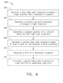
- FIG. 4 is a flow diagram of an exemplary method 200 of operating aircraft 10.
- method 200 includes calculating 202 first flight path trajectory 36 including origin waypoint 40 and destination waypoint 42.
- a tactical command indicating a change in flight trajectory is received 204 by FMS 24.
- FMS 24 determines 206 a present position of aircraft 10 along first flight path trajectory 36.
- FMS 24 also calculates 208 second flight path trajectory 38 based at least in part on the received tactical command, and including departure waypoint 46 along first flight path trajectory 36, intercept waypoint 48 along first flight path trajectory 36, departure vector 50 from departure waypoint 46, and return vector 54 from departure vector 50 to intercept waypoint 48.
- FIG. 5 is a simplified schematic diagram of FMS 24.
- FMS 24 includes a controller 300 that includes a processor 302 and a memory 304.
- Processor 302 and memory 304 are communicatively coupled via a bus 306 to an input-output (I/O) unit 308 that is also communicatively coupled to a plurality of subsystems 310 via a bus 311 or a plurality of dedicated buses.
- subsystems 310 may include an engine subsystem 312, a communications subsystem 314, a cockpit display and input subsystem 316, an autoflight subsystem 318, a trajectory reference subsystem, and/or a navigation subsystem 320. Other subsystems not mentioned and more or fewer subsystems 310 may also be present.
- engine subsystem 312 is configured to generate autothrottle signals to control a speed of aircraft 10 using engines 12.
- Controller 300 is configured to receive input signals from one or more FMS subsystems and to generate signals that may be used to control the thrust of a gas turbine engine, torque and/or speed of an electric motor, or a power output of an internal combustion engine.
- Autoflight subsystem 318 is configured to control the flight surface actuators that change the path of aircraft 10 to follow the flight path trajectory 26 provided by FMS 24.
- Navigation subsystem 320 provides current location information to controller 300.
- Communications subsystem 314 provides communication between the ATC and controller 300 and for transmitting signals to the ATC, and for receiving signals from the ATC.
- cockpit display and input subsystem 316 includes the cockpit displays on which navigation information, aircraft flight parameter information, fuel and engine status and other information are displayed.
- Cockpit display and input subsystem 316 also includes various control panels from which the pilot or navigator may input tactical commands into FMS 24 after having received, for example, an appropriate message from an air traffic controller.
- control panels refer to computer devices that interact directly with humans such as, but not limited to, a keyboard, a mouse, a trackball, a touchpad, a pointing stick, a graphics tablet, a joystick, a driving or flight simulator device, a gear stick, a steering wheel, a foot pedal, a haptic glove, and a gestural interface.
- a flight management system for use with an aircraft provides a cost-effective and reliable means for providing an automated method to compute a flight path trajectory based on tactical commands in order to meet a required time of arrival at a waypoint ahead of the aircraft. More specifically, the methods and systems described herein facilitate determined the intent or future position of the aircraft by generating the flight path trajectory based on possible tactical commands. In addition, the above-described methods and systems facilitate reducing the uncertainty in flight time arrivals and the overall fuel consumption of aircraft in busy airspace that enable more precise aircraft separation and reducing controller workload. As a result, the methods and systems described herein facilitate operating aircraft in a cost-effective and reliable manner.
Landscapes
- Engineering & Computer Science (AREA)
- Radar, Positioning & Navigation (AREA)
- Remote Sensing (AREA)
- Physics & Mathematics (AREA)
- General Physics & Mathematics (AREA)
- Aviation & Aerospace Engineering (AREA)
- Automation & Control Theory (AREA)
- Traffic Control Systems (AREA)
- Navigation (AREA)
- Radar Systems Or Details Thereof (AREA)
Abstract
Description
- The field of the invention relates generally to controlling aircraft in flight, and more specifically, to a flight management system for use with an aircraft and method of operating an aircraft in a controlled airspace.
- At least some known aircraft include flight management systems and for generating a flight path from a departure airport to a destination airport and for flying the aircraft along the generated flight path. In today's airspace, delays due to congestion are common. When the number of aircraft entering an airspace exceeds the number of aircraft that can be safely handled by the available Air Traffic resources (limited by the number of controllers and type of automation), delays are imposed on aircraft. These delays are typically achieved by instructing aircraft to reduce speed, using radar vectors, or by orbital holding. Currently, air traffic controllers estimate, based on experience, using an average flight time to determine when to ask an aircraft to leave its current holding pattern in order to meet a time (for metering or merging with other aircraft in a defined arrival sequence) at a point after leaving the hold, such as within the arrival procedure.
- At least some known aircraft include an autoflight system that includes a flight management system and a separate autopilot system. Currently, a pilot or navigator receives instructions from the air traffic controller when a delaying maneuver is required and manually enters tactical commands into the autopilot system. The autopilot system abandons the flight path generated by the flight management system, and operates the aircraft through the delay maneuver based on the tactical commands. Because the generated flight path has been abandoned, the intent, or future position of the aircraft becomes uncertain. As a result, the flight time will vary significantly based on where the aircraft leaves a delay maneuver, introducing uncertainty which requires additional separation buffers. This uncertainty results in decreased capacity and increased fuel burn for following aircraft due to their increased time spent in the delaying tactical operation.
- In addition, at least some known air traffic controllers may use trajectory based operation methods to maintain aircraft separation. This method requires knowledge of the future aircraft 4-dimensional intent (latitude, longitude, altitude and time). Known autoflight systems do not support trajectory based operation methods because the autopilot system abandons the generated flight path to execute tactical commands received by the air traffic controller.
- An integrated autoflight system is needed that eliminates the undesired uncertainty of an aircraft's intent during implementation of tactical commands. Specifically, an autoflight system is needed that generates a flight path that is indicative of the future aircraft trajectory based on tactical commands, and downlinks the flight path trajectory to the ground controllers to provide the ground controllers with a precise picture of the aircraft's position in time and enable controllers to safely merge aircraft traffic with appropriate separation for approach and landing on an active runway.
- In one embodiment, a flight management system for use in automatically generating a flight path trajectory for an aircraft is provided. The flight path trajectory includes a plurality of waypoints and a plurality of vectors that extend between each waypoint of the plurality of waypoints. The flight management system includes a processor that is configured to calculate a first flight path trajectory including an origin waypoint and a destination waypoint. A tactical command that indicates a change in flight trajectory is received. A second flight path trajectory based at least in part on the tactical command is calculated. The calculated second flight path trajectory includes a departure waypoint along the first flight path trajectory, an intercept waypoint along the first flight path trajectory, and a departure vector from the departure waypoint to the intercept waypoint.
- In another embodiment, a method of operating an aircraft that includes a flight management system is provided. The method includes calculating, by the flight management system, a first flight path trajectory including an origin waypoint and a destination waypoint. A tactical command indicating a change in flight trajectory is receiving by the aircraft flying in the first flight path trajectory. The flight management system calculates a second flight path trajectory based at least in part on the tactical command. The calculated second flight path trajectory includes a departure waypoint along the first flight path trajectory, an intercept waypoint along the first flight path trajectory, and a departure vector from the departure waypoint to the intercept waypoint.
- In yet another embodiment, an aircraft including a flight management system is provided. The flight management system includes a processor that is configured to calculate a first flight path trajectory including an origin waypoint and a destination waypoint. A tactical command indicating a change in flight trajectory is received. A second flight path trajectory is calculated based at least in part on the tactical command. The calculated second flight path trajectory includes a departure waypoint along the first flight path trajectory, an intercept waypoint along the first flight path trajectory, and a departure vector from the departure waypoint to the intercept waypoint.
-
-
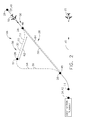
FIG. 1 is a side elevational view of a vehicle such as an aircraft including an exemplary Flight Management System (FMS); -
FIG. 2 is a schematic diagram of an exemplary flight path trajectory that is generated by the exemplary FMS from an elevated view above an aircraft. -
FIG. 3 is another schematic diagram of the flight path trajectory that is generated by the exemplary FMS from a side elevation view of an aircraft. -
FIG. 4 is a flow diagram of an exemplary method of operating the aircraft shown inFIG. 1 . -
FIG. 5 is a simplified schematic diagram of the exemplary FMS suitable for use with the aircraft shown inFIG. 1 . - The exemplary methods and systems described herein overcome at least some disadvantages of known autoflight systems by providing a flight management system that integrates all tactical commands in generating a flight path trajectory. Moreover, the flight management system described herein calculates a flight path trajectory based on a tactical command received from an air traffic controller. By generating a flight path trajectory based on tactical commands, the intent or future position of the aircraft can be determined based on the generated flight path trajectory that enables the air traffic controller to reduce the uncertainty in flight time arrivals and reduce additional separation buffers between aircraft.
- As used herein, an element or step recited in the singular and proceeded with the word "a" or "an" should be understood as not excluding plural elements or steps, unless such exclusion is explicitly recited. Furthermore, references to "one embodiment" of the present invention are not intended to be interpreted as excluding the existence of additional embodiments that also incorporate the recited features.
-
FIG. 1 is a side elevational view of avehicle 10 such as an aircraft in accordance with an embodiment of the present disclosure.Aircraft 10 includes one ormore propulsion engines 12 coupled to afuselage 14, acockpit 16 positioned infuselage 14,wing assemblies 18 extending outward fromfuselage 14, atail assembly 20, alanding assembly 22, a flight management system (FMS) 24 (not visible) for generating a flight path trajectory andflying vehicle 10 along the flight path trajectory, and a plurality of other systems and subsystems that enable proper operation ofvehicle 10. -
FIG. 2 is a schematic diagram of aflight path trajectory 26 that is generated by FMS 24 from an elevated view aboveaircraft 10.FIG. 3 is another schematic diagram offlight path trajectory 26 that is generated by FMS 24 from a side elevation view ofaircraft 10. In the exemplary embodiment, FMS 24 is configured to calculate a plurality offlight path trajectories 26. Eachflight path trajectory 26 includes a plurality ofwaypoints 28 and a plurality ofvectors 30. Eachwaypoint 28 includes a position in a 4-dimensional space that includes a point in a 3-dimensional coordinate system and an expected time of arrival. In one embodiment,waypoint 28 may include, for example, a latitude coordinate, a longitude coordinate, and an altitude coordinate. In the exemplary embodiment, eachvector 30 extends betweenadjacent waypoints 28 to defineflight path trajectory 26. In one embodiment,vector 30 extends between a first waypoint 32 and a second waypoint 34, and includes a series of maneuvers that are performed byaircraft 10 to enableaircraft 10 to travel from first waypoint 32 to second waypoint 34, such thataircraft 10 arrives at second waypoint 34 at a predefined period of time. - In the exemplary embodiment, FMS 24 is configured to calculate a first
flight path trajectory 36 and a secondflight path trajectory 38. Firstflight path trajectory 36 includes a first waypoint, i.e. anorigin waypoint 40, a second waypoint, i.e. adestination waypoint 42, and at least onevector 30 fromorigin waypoint 40 todestination waypoint 42.Destination waypoint 42 may include, for example, an airport, or an approach point. In the exemplary embodiment, firstflight path trajectory 36 also includes third waypoint, i.e. amerge waypoint 44 that is betweenorigin waypoint 40 anddestination waypoint 42. Mergewaypoint 44 includes a point at which firstflight path trajectory 36 intersects with aflight path trajectory 26 of anincoming aircraft 45. In the exemplary embodiment, FMS 24 calculates a period of time to complete firstflight path trajectory 36 and an estimated time of arrival (ETA) atdestination waypoint 42 and/or mergewaypoint 44. When inbound traffic exceeds the capability of an airport or airspace, an air traffic controller (ATC) determines an adjusted time of arrival atdestination waypoint 42 and/or mergewaypoint 44 to provide a predefined period of separation betweenaircraft 10 and incomingaircraft 45. In the exemplary embodiment, FMS 24 is configured to receive a signal indicative of the adjusted time of arrival atmerge waypoint 44, and to calculate secondflight path trajectory 38 based at least in part on the adjusted time of arrival. In the exemplary embodiment,FMS 24 is configured to calculate secondflight path trajectory 38 to adjust a period of time required to reachmerge waypoint 44 such that theaircraft 10 arrives amerge waypoint 44 at the adjusted time of arrival. - In the exemplary embodiment,
FMS 24 calculates secondflight path trajectory 38 including adeparture waypoint 46 along firstflight path trajectory 36, anintercept waypoint 48 along firstflight path trajectory 36, and adeparture vector 50 fromdeparture waypoint 46 to interceptwaypoint 48. In one embodiment, secondflight path trajectory 38 includes areturn waypoint 52 that is betweendeparture waypoint 46 andintercept waypoint 48 such thatdeparture vector 50 begins atdeparture waypoint 46 and extends to returnwaypoint 52, and areturn vector 54 begins atreturn waypoint 52 and extends to interceptwaypoint 48. In the exemplary embodiment,FMS 24 is configured to calculate secondflight path trajectory 38 to depart from firstflight path trajectory 36 atdeparture waypoint 46 and return to firstflight path trajectory 36 atintercept waypoint 48. - During operation of
aircraft 10, the ATC determines a required time of arrival (RTA) atmerge waypoint 44 that is different than the calculated ETA of firstflight path trajectory 36.FMS 24 receives a signal indicative of the RTA atmerge waypoint 44, and determines the present position ofaircraft 10 along firstflight path trajectory 36.FMS 24 calculatesdeparture waypoint 46 from firstflight path trajectory 36, and calculates secondflight path trajectory 38 to include a period of time required to complete secondflight path trajectory 38, and calculates an ETA atmerge waypoint 44 that is approximately equal to the RTA.FMS 24 calculates the ETA atmerge waypoint 44 based on a length ofdeparture vector 50, a length ofreturn vector 54, a speed ofaircraft 10, and any external influences, such as, but not limited to, wind speed and direction. In one embodiment,FMS 24 is configured to calculateintercept waypoint 48 along firstflight path trajectory 36, and to calculatedeparture vector 50 to returnaircraft 10 to firstflight path trajectory 36 after completing secondflight path trajectory 38.FMS 24maneuvers aircraft 10 to enter secondflight path trajectory 38 atdeparture waypoint 46 and to returnaircraft 10 to firstflight path trajectory 36 atintercept waypoint 48. - In the exemplary embodiment,
FMS 24 receives a signal indicative of a tactical command to adjustflight path trajectory 26 ofaircraft 10. In one embodiment, the ATC transmits a signal toFMS 24 indicative of the tactical command. Alternatively, a pilot or navigator may input tactical commands intoFMS 24 after having received, for example, an appropriate message from the ATC. In the exemplary embodiment,FMS 24 is configured to calculate secondflight path trajectory 38 based at least in part on the tactical command. In one embodiment,FMS 24 calculates an ETA atdestination waypoint 42 and/or mergewaypoint 44 based on the tactical command, and transmit a signal indicative of the calculated ETA to the ATC. The ATC compares the calculated ETA with a required time of arrival, and releasesaircraft 10 from the tactical command when the calculated ETA is approximately equal to an RTA atdestination waypoint 42 and/or mergewaypoint 44. In one embodiment,FMS 24 receives, from the ATC, a signal indicative of a flight path trajectory 56 ofincoming aircraft 45 that may intersect firstflight path trajectory 36 ofaircraft 10.FMS 24 is configured to calculate secondflight path trajectory 38 including aclearance distance 58 and or clearance time betweenincoming aircraft 45 andaircraft 10 to avoidincoming aircraft 45. - In the exemplary embodiment,
FMS 24 receives a tactical command including a headingvector command 60.FMS 24 is configured to calculate secondflight path trajectory 38 based at least in part on headingvector command 60. In the exemplary embodiment,FMS 24 is configured to calculatedeparture vector 50 to maintain headingvector command 60 for a predefined period oftime 62.FMS 24 is also configured to calculate a time to complete secondflight path trajectory 38 and calculate an ETA at a selectable waypoint, such asintercept waypoint 48,destination waypoint 42, and/or mergewaypoint 44. Alternatively,FMS 24 is configured to receive a signal indicative of a RTA atdestination waypoint 42 and/orintercept waypoint 48, and calculate a period oftime 62 to maintain headingvector command 60 to meet a RTA at theintercept waypoint 48 and/or atdestination waypoint 42. - In an alternative embodiment,
FMS 24 receives a tactical command including anairspeed vector command 64.FMS 24 is configured to calculate secondflight path trajectory 38 based on tacticalairspeed vector command 64.FMS 24 is also configured to calculate an amount of time to complete secondflight path trajectory 38, and calculate an ETA atintercept waypoint 48 and/or atdestination waypoint 42. - In one embodiment,
FMS 24 receives a tactical command including analtitude vector command 66.FMS 24 is configured to calculate secondflight path trajectory 38 based on tacticalaltitude vector command 66. In the exemplary embodiment,FMS 24 is configured to calculatedeparture vector 50 to maintainaltitude vector command 66 for a predefined period oftime 68, and calculate an ETA atintercept waypoint 48 and/or atdestination waypoint 42. In one embodiment,FMS 24 is configured to receive a signal indicative of a RTA atdestination waypoint 42 and/or atintercept waypoint 48, and calculate a period oftime 68 to maintainaltitude vector command 66 to meet the RTA at theintercept waypoint 48 and/or atdestination waypoint 42. In one embodiment,FMS 24 is configured to calculatedeparture vector 50 to include a clearance altitude betweenincoming aircraft 45 andaircraft 10. - In an alternative embodiment,
FMS 24 receives atactical command 70 that includes a flight path angle command or a vertical speed command.FMS 24 is configured to calculate secondflight path trajectory 38 based ontactical command 70, and calculate an ETA atintercept waypoint 48 and/or atdestination waypoint 42. - In the exemplary embodiment,
FMS 24 is configured to calculate a tactical performance envelope foraircraft 10 based at least on part on performance parameters such as, for example, engine performance, aircraft operational weight, and/or environmental factors (e.g. wind direction, wind speed, and/or air density). As used herein, the term "tactical performance envelope" refers to a range of operating capabilities with respect to a tactical command based on aircraft performance parameters. The range of operating capabilities may include, but are not limited to including maximum altitude, minimum altitude, maximum airspeed, minimum airspeed, maximum flight path angle, minimum flight path angle, maximum vertical speed, and/or minimum vertical speed. - In the exemplary embodiment,
FMS 24 receives atactical command 70 from ATC and will determine if the received tactical command is within the tactical performance envelop with respect to the received tactical command.FMS 24 will notify the pilot if the received tactical command is not within the tactical performance envelop and calculate secondflight path trajectory 38 such thatdeparture vector 50 and/or returnvector 54 are within the tactical performance envelop. In one embodiment, the pilot may manually select a tactical command to operateaircraft 10 outside of the tactical performance envelop. -
FIG. 4 is a flow diagram of anexemplary method 200 of operatingaircraft 10. In the exemplary embodiment,method 200 includes calculating 202 firstflight path trajectory 36 includingorigin waypoint 40 anddestination waypoint 42. A tactical command indicating a change in flight trajectory is received 204 byFMS 24.FMS 24 determines 206 a present position ofaircraft 10 along firstflight path trajectory 36.FMS 24 also calculates 208 secondflight path trajectory 38 based at least in part on the received tactical command, and includingdeparture waypoint 46 along firstflight path trajectory 36,intercept waypoint 48 along firstflight path trajectory 36,departure vector 50 fromdeparture waypoint 46, and returnvector 54 fromdeparture vector 50 to interceptwaypoint 48. - In one embodiment,
FMS 24 receives 210 a RTA atdestination waypoint 42 from the ATC.FMS 24 calculates 212 secondflight path trajectory 38 to meet the RTA atdestination waypoint 42. Alternatively,FMS 24 receives a RTA at a selectable waypoint downstream of the current aircraft position, for example, atintercept waypoint 48, and calculatesdeparture vector 50 to meet the RTA atintercept waypoint 48. - In an alternative embodiment,
FMS 24 receives a first tactical command from the ATC, and calculates a period of time to complete secondflight path trajectory 38 based on the received first tactical command, the aircraft's current position, target speed, wind and temperature data.FMS 24 calculates an ETA atdestination waypoint 42 based on the calculated time to complete secondflight path trajectory 38.FMS 24 transmits a signal indicative of the calculated ETA to the ATC. The ATC determines whether the calculated ETA is within a predefined range of RTA, and transmits a second tactical command to adjust the ETA to within the predefined range of RTA's.FMS 24 receives the second tactical command from the ATC and calculates secondflight path trajectory 38 based on the received second tactical command to adjust the calculated ETA of secondflight path trajectory 38 to within the predefined range of RTA's. - In one embodiment,
FMS 24 receives a tactical command including headingvector command 60 and calculatesdeparture vector 50 to maintain headingvector command 60 for a predefined period of time.FMS 24 calculates an amount of time to complete secondflight path trajectory 38 and calculates an ETA to interceptwaypoint 48. Alternatively,FMS 24 receives a RTA atdestination waypoint 42 from the ATC, and calculatesdeparture vector 50 to maintain headingvector command 60 for a period of time to meet the RTA atdestination waypoint 42. - In an alternative embodiment,
FMS 24 receives a tactical command includingaltitude vector command 66, calculatesdeparture vector 50 to maintain the altitude vector command for a predefined period of time, and calculates an ETA to interceptwaypoint 48. Alternatively, FMS receives a RTA atintercept waypoint 48 and calculatesdeparture vector 50 to maintain the altitude vector command to meet the RTA atdestination waypoint 42. - In one embodiment,
FMS 24 receives a tactical command including anairspeed vector command 64.FMS 24 calculates secondflight path trajectory 38 based on received tacticalairspeed vector command 64, and calculates an amount of time to complete secondflight path trajectory 38. In an alternative embodiment,FMS 24 receives a tactical command includingaltitude vector command 66, and calculates secondflight path trajectory 38 based on the receivedaltitude vector command 66, and calculates an ETA atintercept waypoint 48. In another alternative embodiment,FMS 24 receives a tactical command including flight path angle orvertical speed command 70, and calculates secondflight path trajectory 38 based on the received flight path angle orvertical speed command 70. -
FIG. 5 is a simplified schematic diagram ofFMS 24. In the exemplary embodiment,FMS 24 includes acontroller 300 that includes aprocessor 302 and amemory 304.Processor 302 andmemory 304 are communicatively coupled via abus 306 to an input-output (I/O)unit 308 that is also communicatively coupled to a plurality ofsubsystems 310 via abus 311 or a plurality of dedicated buses. In various embodiments,subsystems 310 may include anengine subsystem 312, acommunications subsystem 314, a cockpit display andinput subsystem 316, anautoflight subsystem 318, a trajectory reference subsystem, and/or anavigation subsystem 320. Other subsystems not mentioned and more orfewer subsystems 310 may also be present. - In the exemplary embodiment,
engine subsystem 312 is configured to generate autothrottle signals to control a speed ofaircraft 10 usingengines 12.Controller 300 is configured to receive input signals from one or more FMS subsystems and to generate signals that may be used to control the thrust of a gas turbine engine, torque and/or speed of an electric motor, or a power output of an internal combustion engine.Autoflight subsystem 318 is configured to control the flight surface actuators that change the path ofaircraft 10 to follow theflight path trajectory 26 provided byFMS 24.Navigation subsystem 320 provides current location information tocontroller 300. Communications subsystem 314 provides communication between the ATC andcontroller 300 and for transmitting signals to the ATC, and for receiving signals from the ATC. - In the exemplary embodiment, cockpit display and
input subsystem 316 includes the cockpit displays on which navigation information, aircraft flight parameter information, fuel and engine status and other information are displayed. Cockpit display andinput subsystem 316 also includes various control panels from which the pilot or navigator may input tactical commands intoFMS 24 after having received, for example, an appropriate message from an air traffic controller. As used herein, control panels refer to computer devices that interact directly with humans such as, but not limited to, a keyboard, a mouse, a trackball, a touchpad, a pointing stick, a graphics tablet, a joystick, a driving or flight simulator device, a gear stick, a steering wheel, a foot pedal, a haptic glove, and a gestural interface. In the exemplary embodiment, cockpit display andinput subsystem 316 includes a headingcommand input 322 for receiving a heading vector command, an airspeedvector command input 324 for receiving airspeed vector command, a vertical speed/flight command input 326 for receiving an altitude vector command, and an altitudevector command input 328 for receiving an altitude vector command. Alternatively, cockpit display andinput subsystem 316 includes any suitable tactical command inputs that enableFMS 24 to function as described herein. - While
FIG. 5 illustrates a particular architecture suitable for executing method 300 (shown inFIG. 4 ) other architectures forFMS 24 can also be used. - In the exemplary embodiment, computer instructions for executing
method 300 reside inmemory 304 along with map, waypoint, holding pattern and other information useful for determining the desired flight paths, waypoints, turns and other aircraft maneuvers. AsFMS 24 executesmethod 300 it uses information fromnavigation subsystem 320 and aircraft performance information stored inmemory 304. Such information is conveniently entered by the pilot or navigator via cockpit display andinput subsystem 316, received from the ATC, and/or obtained from non-transient computer-readable media, for example CD ROMs containing such information, signals received from offboard control systems, or a combination thereof. - In the exemplary embodiment,
FMS 24 may be configured to commandautoflight subsystem 318 to move the flight control surfaces of the aircraft without direct human intervention to achieve flight alongflight path trajectory 26. Alternatively, if the autoflight is disengaged,FMS 24 can provide course change directions or suggestions to the pilot via, for example, display in cockpit display andinput subsystem 316, which when followed by the pilot, causes the plane to fly alongflight path trajectory 26.Controller 300 may be embodied in a standalone hardware device or may be exclusively a firmware and/or software construct executing onFMS 24 or other vehicle system. - The term processor, as used herein, refers to central processing units, microprocessors, microcontrollers, reduced instruction set circuits (RISC), application specific integrated circuits (ASIC), logic circuits, and any other circuit or processor capable of executing the functions described herein.
- As used herein, the terms "software" and "firmware" are interchangeable, and include any computer program stored in memory for execution by
processor 302, including RAM memory, ROM memory, EPROM memory, EEPROM memory, and non-volatile RAM (NVRAM) memory. The above memory types are exemplary only, and are thus not limiting as to the types of memory usable for storage of a computer program. - As will be appreciated based on the foregoing specification, the above-described embodiments of the disclosure may be implemented using computer programming or engineering techniques including computer software, firmware, hardware or any combination or subset thereof, wherein the technical effect is provided by an efficient, automated computation on an aircraft to replace manual, and often inaccurate computations that are currently performed by the air traffic controller. Any such resulting program, having computer-readable code means, may be embodied or provided within one or more computer-readable media, thereby making a computer program product, i.e., an article of manufacture, according to the discussed embodiments of the disclosure. The computer-readable media may be, for example, but is not limited to, a fixed (hard) drive, diskette, optical disk, magnetic tape, semiconductor memory such as read-only memory (ROM), and/or any transmitting/receiving medium such as the Internet or other communication network or link. The article of manufacture containing the computer code may be made and/or used by executing the code directly from one medium, by copying the code from one medium to another medium, or by transmitting the code over a network.
- An exemplary technical effect of the system, method, and apparatus described herein includes at least one of: (a) calculating, by a flight management system, a first flight path trajectory including an origin waypoint and a destination waypoint; (b) receiving, by an aircraft flying in the first flight path trajectory, a tactical command indicating a change in flight trajectory; (c) determining a present position of the aircraft along the first flight path trajectory; (d) calculating, by the flight management system, a second flight path trajectory based at least in part on the tactical command.
- The above-described embodiments of a flight management system for use with an aircraft provides a cost-effective and reliable means for providing an automated method to compute a flight path trajectory based on tactical commands in order to meet a required time of arrival at a waypoint ahead of the aircraft. More specifically, the methods and systems described herein facilitate determined the intent or future position of the aircraft by generating the flight path trajectory based on possible tactical commands. In addition, the above-described methods and systems facilitate reducing the uncertainty in flight time arrivals and the overall fuel consumption of aircraft in busy airspace that enable more precise aircraft separation and reducing controller workload. As a result, the methods and systems described herein facilitate operating aircraft in a cost-effective and reliable manner.
- Exemplary embodiments of a method, system, and apparatus for a flight management system for use in an aircraft are described above in detail. The system, method, and apparatus are not limited to the specific embodiments described herein, but rather, components of systems and/or steps of the methods may be utilized independently and separately from other components and/or steps described herein. For example, the methods may also be used in combination with other flight management systems and methods, and are not limited to practice with only the aircraft engine systems and methods as described herein. Rather, the exemplary embodiment can be implemented and utilized in connection with many other propulsion system applications.
- Although specific features of various embodiments of the invention may be shown in some drawings and not in others, this is for convenience only. In accordance with the principles of the invention, any feature of a drawing may be referenced and/or claimed in combination with any feature of any other drawing.
- This written description uses examples to disclose the invention, including the best mode, and also to enable any person skilled in the art to practice the invention, including making and using any devices or systems and performing any incorporated methods. The patentable scope of the invention is defined by the claims, and may include other examples that occur to those skilled in the art. Such other examples are intended to be within the scope of the claims if they have structural elements that do not differ from the literal language of the claims, or if they include equivalent structural elements with insubstantial differences from the literal language of the claims.
- Various aspects and embodiments on the invention are indicated in the following clauses:
- 1. A flight management system for use in automatically generating a flight path trajectory for an aircraft, the flight path trajectory including a plurality of waypoints and a plurality of vectors extending between each waypoint of the plurality of waypoints, said flight management system comprising a processor configured to:
- calculate a first flight path trajectory including an origin waypoint and a destination waypoint;
- receive a tactical command indicating a change in flight trajectory; and
- calculate a second flight path trajectory based at least in part on the tactical command, the calculated second flight path trajectory including a departure waypoint along the first flight path trajectory, an intercept waypoint along the first flight path trajectory, and a departure vector from the departure waypoint to the intercept waypoint.
- 2. A flight management system in accordance with Clause 1, wherein said processor is further configured to calculate the departure vector to meet a required time of arrival (RTA) at a selectable waypoint along the second flight path trajectory.
- 3. A flight management system in accordance with Clause 1, wherein said processor is further configured to:
- receive a RTA at a merge waypoint along the first flight path trajectory; and
- calculate the second flight path trajectory to meet the RTA at the merge waypoint.
- 4. A flight management system in accordance with Clause 1, wherein the tactical command includes a heading vector command, said processor further configured to calculate the second flight path trajectory including a departure vector that includes maintaining the heading vector for a predefined period of time.
- 5. A flight management system in accordance with
Clause 4, wherein said processor is further configured to calculate a period of time to maintain the heading vector to meet a RTA at the destination waypoint. - 6. A flight management system in accordance with Clause 1, wherein the tactical command includes an altitude vector command, said processor further configured to calculate the departure vector including maintaining the altitude for a predefined period of time.
- 7. A flight management system in accordance with Clause 1, wherein the tactical command includes an airspeed vector command, said processor further configured to calculate the second flight path trajectory based on the tactical airspeed command.
- 8. A flight management system in accordance with Clause 1, wherein the tactical command includes one of a flight path angle command and a vertical speed command.
- 9. A method of operating an aircraft including a flight management system, the method comprising:
- calculating, by the flight management system, a first flight path trajectory including an origin waypoint and a destination waypoint;
- receiving, by the aircraft flying in the first flight path trajectory, a tactical command indicating a change in flight trajectory; and
- calculating, by the flight management system, a second flight path trajectory based at least in part on the tactical command, the calculated second flight path trajectory including a departure waypoint along the first flight path trajectory, an intercept waypoint along the first flight path trajectory, and a departure vector from the departure waypoint to the intercept waypoint.
- 10. A method in accordance with Clause 9, further comprising:
- receiving a RTA at a merge waypoint along the first flight path trajectory; and
- calculating the second flight path trajectory to meet the RTA at the merge waypoint.
- 11. A method in accordance with Clause 9, further comprising:
- calculating the second flight path trajectory such that the departure vector is within a predefined tactical performance envelope.
- 12. A method in accordance with Clause 9, further comprising:
- receiving a tactical command including a heading vector command;
- calculating the departure vector to maintain the heading vector command for a predefined period of time.
- 13. A method in accordance with Clause 9, further comprising
receiving a tactical command including an altitude vector command; and
calculating the departure vector to maintain the altitude vector command for a predefined period of time. - 14. A method in accordance with Clause 9, further comprising
receiving a tactical command including an airspeed vector command; and
calculating the second flight path trajectory based on the tactical airspeed vector command. - 15. A method in accordance with Clause 9, further comprising:
- receiving a tactical command including a flight path angle command;
- calculating the second flight pan trajectory based on the flight path angle command.
- 16. An aircraft comprising:
- a flight management system comprising a processor, said processor configured to:
- calculate a first flight path trajectory including an origin waypoint and a destination waypoint;
- receive a tactical command indicating a change in flight trajectory; and
- calculate a second flight path trajectory based at least in part on the tactical command, the calculated second flight path trajectory including a departure waypoint along the first flight path trajectory, an intercept waypoint along the first flight path trajectory, and a departure vector from the departure waypoint to the intercept waypoint.
- a flight management system comprising a processor, said processor configured to:
- 17. An aircraft in accordance with
Clause 16, wherein the tactical command includes a heading vector command, said processor further configured to calculate the second flight path trajectory including a departure vector that includes maintaining the heading vector for a predefined period of time. - 18. An aircraft in accordance with
Clause 16, wherein the tactical command includes an altitude vector command, said processor further configured to calculate the departure vector including maintaining the altitude for a period of time. - 19. An aircraft in accordance with
Clause 16, wherein the tactical command includes an airspeed vector command, said processor further configured to calculate the second flight path trajectory based on the tactical airspeed vector command. - 20. An aircraft in accordance with
Clause 16, wherein the tactical command includes one of a flight path angle and a vertical speed command.
Claims (16)
- A flight management system (24) for use in automatically generating a flight path trajectory (26) for an aircraft (10), the flight path trajectory including a plurality of waypoints (28) and a plurality of vectors (30) extending between each waypoint of the plurality of waypoints, said flight management system comprising a processor (302) configured to:calculate a first flight path trajectory (36) including an origin waypoint (40) and a destination waypoint (42);receive a tactical command indicating a change in flight trajectory; andcalculate a second flight path trajectory (38) based at least in part on the tactical command, the calculated second flight path trajectory including a departure waypoint along the first flight path trajectory, an intercept waypoint (48) along the first flight path trajectory, and a departure vector (50) from the departure waypoint (46) to the intercept waypoint.
- A flight management system (24) in accordance with Claim 1, wherein said processor (302) is further configured to calculate the departure vector (50) to meet a required time of arrival (RTA) at a selectable waypoint (28) along the second flight path trajectory (38).
- A flight management system (24) in accordance with either of Claim 1 or 2, wherein said processor (302) is further configured to:receive a RTA at a merge waypoint (44) along the first flight path trajectory (36);
andcalculate the second flight path trajectory (38) to meet the RTA at the merge waypoint. - A flight management system (24) in accordance with any preceding claim, wherein the tactical command (70) includes a heading vector command (60), said processor (302)further configured to calculate the second flight path trajectory (38) including a departure vector (50) that includes maintaining the heading vector for a predefined period of time.
- A flight management system (24) in accordance with Claim 4, wherein said processor (302) is further configured to calculate a period of time to maintain the heading vector to meet a RTA at the destination waypoint (42).
- A flight management system (24) in accordance with any preceding claim, wherein the tactical command (70) includes an altitude vector command (64), said processor (302) further configured to calculate the departure vector including maintaining the altitude for a predefined period of time.
- A flight management system (24) in accordance with any preceding claim, wherein the tactical command (70) includes an airspeed vector command (64), said processor (302) further configured to calculate the second flight path trajectory (38) based on the tactical airspeed command.
- A flight management system (24) in accordance with any preceding claim, wherein the tactical command (70) includes one of a flight path angle command and a vertical speed command.
- An aircraft (10) comprising:a flight management system (24) comprising a processor (302), said processor configured to:calculate a first flight path trajectory (36) including an origin waypoint (40) and a destination waypoint (42);receive a tactical command (70) indicating a change in flight trajectory; andcalculate a second flight path trajectory (38) based at least in part on the tactical command, the calculated second flight path trajectory including a departure waypoint (46) along the first flight path trajectory, an intercept waypoint (48) along the first flight path trajectory, and a departure vector from the departure waypoint to the intercept waypoint.
- An aircraft (10) in accordance with Claim 9, wherein the tactical command (70) includes a heading vector command (60), said processor (302) further configured to calculate the second flight path trajectory (38) including a departure vector (50) that includes maintaining the heading vector for a predefined period of time.
- A method of operating an aircraft including a flight management system, the method comprising:calculating, by the flight management system, a first flight path trajectory including an origin waypoint and a destination waypoint;receiving, by the aircraft flying in the first flight path trajectory, a tactical command indicating a change in flight trajectory; andcalculating, by the flight management system, a second flight path trajectory based at least in part on the tactical command, the calculated second flight path trajectory including a departure waypoint along the first flight path trajectory, an intercept waypoint along the first flight path trajectory, and a departure vector from the departure waypoint to the intercept waypoint.
- A method in accordance with Claim 11, further comprising:receiving a RTA at a merge waypoint along the first flight path trajectory; andcalculating the second flight path trajectory to meet the RTA at the merge waypoint.
- A method in accordance with either of claim 11 or 12, further comprising:calculating the second flight path trajectory such that the departure vector is within a predefined tactical performance envelope.
- A method in accordance with any of Claims 11 to 13, further comprising:receiving a tactical command including a heading vector command;calculating the departure vector to maintain the heading vector command for a predefined period of time.
- A method in accordance with any of Claims 11 to 14, further comprising receiving a tactical command including an altitude vector command; and calculating the departure vector to maintain the altitude vector command for a predefined period of time.
- A method in accordance with any of Claims 11 to 15, further comprising receiving a tactical command including an airspeed vector command; and calculating the second flight path trajectory based on the tactical airspeed vector command.
Applications Claiming Priority (1)
| Application Number | Priority Date | Filing Date | Title |
|---|---|---|---|
| US12/986,838 US8494766B2 (en) | 2011-01-07 | 2011-01-07 | Flight management system with integrated tactical commands for use with an aircraft and method of operating same |
Publications (3)
| Publication Number | Publication Date |
|---|---|
| EP2474812A2 true EP2474812A2 (en) | 2012-07-11 |
| EP2474812A3 EP2474812A3 (en) | 2013-08-28 |
| EP2474812B1 EP2474812B1 (en) | 2018-10-31 |
Family
ID=45495744
Family Applications (1)
| Application Number | Title | Priority Date | Filing Date |
|---|---|---|---|
| EP12150189.4A Active EP2474812B1 (en) | 2011-01-07 | 2012-01-04 | Flight management system with integrated tactical commands for use with an aircraft and method of operating same |
Country Status (7)
| Country | Link |
|---|---|
| US (1) | US8494766B2 (en) |
| EP (1) | EP2474812B1 (en) |
| JP (1) | JP6001855B2 (en) |
| CN (1) | CN102591354B (en) |
| BR (1) | BR102012000072B1 (en) |
| CA (1) | CA2763334C (en) |
| IN (1) | IN2012DE00006A (en) |
Cited By (6)
| Publication number | Priority date | Publication date | Assignee | Title |
|---|---|---|---|---|
| FR2993974A1 (en) * | 2012-07-27 | 2014-01-31 | Thales Sa | METHOD FOR CONSTRUCTING A TRACK OF AN AIRCRAFT BY STATE VECTOR |
| CN104851322A (en) * | 2015-05-28 | 2015-08-19 | 西安尚安隆软件科技有限公司 | Low-altitude flight target warning system and low-altitude flight target warning method based on Beidou satellite navigation system |
| WO2015130724A1 (en) * | 2014-02-28 | 2015-09-03 | Qualcomm Incorporated | Method and apparatus for tracking objects with location and motion correlation |
| CN108028024A (en) * | 2015-12-28 | 2018-05-11 | Kddi株式会社 | Flyer control device, clearance spatial domain initialization system, flyer control method and program |
| EP3432294A1 (en) * | 2017-07-19 | 2019-01-23 | Honeywell International Inc. | System and method for providing visualization aids for effective interval management procedure execution |
| EP3657471A1 (en) * | 2018-11-16 | 2020-05-27 | Honeywell International Inc. | Method and system for engaging a vertical navigation descent mode for an aircraft |
Families Citing this family (46)
| Publication number | Priority date | Publication date | Assignee | Title |
|---|---|---|---|---|
| US8494766B2 (en) * | 2011-01-07 | 2013-07-23 | Ge Aviation Systems, Llc | Flight management system with integrated tactical commands for use with an aircraft and method of operating same |
| US9424753B2 (en) | 2011-07-08 | 2016-08-23 | General Electric Company | Simplified user interface for an aircraft |
| US8761971B2 (en) * | 2012-01-11 | 2014-06-24 | The Boeing Company | Auto-flight system pilot interface |
| FR2993973B1 (en) * | 2012-07-27 | 2016-11-04 | Thales Sa | METHOD OF PROCESSING A FLIGHT PLAN |
| RU2537201C2 (en) * | 2012-11-23 | 2014-12-27 | Открытое акционерное общество "Российская самолетостроительная корпорация "МиГ" (ОАО "РСК "МиГ") | Method of aircraft control in landing approach |
| EP2801963B1 (en) * | 2013-05-09 | 2016-01-20 | The Boeing Company | Providing a description of aircraft intent |
| US8868328B1 (en) * | 2013-06-04 | 2014-10-21 | The Boeing Company | System and method for routing decisions in a separation management system |
| CN103354041B (en) * | 2013-06-25 | 2015-12-09 | 上海交通大学 | A kind of civil aircraft terrain perception and warning system pattern four alarm envelope curve generation method |
| US20160085238A1 (en) * | 2013-08-30 | 2016-03-24 | Insitu, Inc. | Display of terrain along flight paths |
| EP2849167B1 (en) * | 2013-09-13 | 2016-04-27 | The Boeing Company | Method for controlling aircraft arrivals at a waypoint |
| US20150308833A1 (en) * | 2014-04-29 | 2015-10-29 | Honeywell International Inc. | System and method for displaying context sensitive notes |
| FR3024231B1 (en) * | 2014-07-28 | 2019-12-20 | Airbus Operations | METHOD AND DEVICE FOR DETERMINING AN OPERATIONAL DISTANCE FROM AN INDETERMINALLY TERMINATED SEGMENT OF AN AIRCRAFT FLIGHT PLAN. |
| US9665345B2 (en) * | 2014-07-29 | 2017-05-30 | Honeywell International Inc. | Flight deck multifunction control display unit with voice commands |
| DE112015003912T5 (en) * | 2014-08-27 | 2017-05-11 | Gulfstream Aerospace Corporation | Aircraft and instrumentation system for voice transcription of radio communications |
| FR3030794B1 (en) * | 2014-12-23 | 2016-12-23 | Thales Sa | METHOD AND SYSTEM FOR GUIDING AN AIRCRAFT |
| FR3031175B1 (en) * | 2014-12-30 | 2019-11-29 | Thales | METHOD FOR AUTOMATICALLY JOINING A ROAD OF AN AIRCRAFT |
| US10373507B2 (en) * | 2015-02-13 | 2019-08-06 | Passur Aerospace, Inc. | System and method for calculating estimated time of runway landing and gate arrival for aircraft |
| US9928747B2 (en) * | 2015-03-31 | 2018-03-27 | The Boeing Company | System and method for calculating a fuel consumption differential corresponding to an aircraft trajectory revision |
| KR20180015190A (en) * | 2015-06-02 | 2018-02-12 | 샌델 에이비아닉스 인코포레이티드 | Method and system for route guidance panel |
| US9536435B1 (en) | 2015-07-13 | 2017-01-03 | Double Black Aviation Technology L.L.C. | System and method for optimizing an aircraft trajectory |
| CN119645078A (en) | 2015-09-15 | 2025-03-18 | 深圳市大疆创新科技有限公司 | System and method for controlling a movable object tracking target |
| US10801841B1 (en) * | 2015-10-29 | 2020-10-13 | National Technology & Engineering Solutions Of Sandia, Llc | Trajectory prediction via a feature vector approach |
| EP3368957B1 (en) | 2015-10-30 | 2022-02-09 | SZ DJI Technology Co., Ltd. | Systems and methods for uav path planning and control |
| US20170174358A1 (en) * | 2015-12-22 | 2017-06-22 | Gulfstream Aerospace Corporation | Systems and methods for multilingual aircraft towing collision warning |
| US10271021B2 (en) * | 2016-02-29 | 2019-04-23 | Microsoft Technology Licensing, Llc | Vehicle trajectory determination to stabilize vehicle-captured video |
| US9663241B1 (en) * | 2016-04-19 | 2017-05-30 | Honeywell International Inc. | Speed change and acceleration point enhancement system and method |
| CN105825719B (en) * | 2016-05-09 | 2019-09-10 | 深圳一电航空技术有限公司 | The generation method and device in unmanned plane inspection course line |
| CN106094846A (en) * | 2016-05-31 | 2016-11-09 | 中国航空工业集团公司西安飞机设计研究所 | A kind of aircraft flight control methods |
| FR3055958B1 (en) * | 2016-09-13 | 2020-04-24 | Thales | DECISION ASSISTANCE FOR THE REVISION OF A FLIGHT PLAN |
| CN106485954B (en) * | 2016-10-14 | 2019-02-01 | 中国民航大学 | Approach path dynamic optimization method in busy termination environment based on the air route Point Merge structure |
| WO2018118070A1 (en) * | 2016-12-22 | 2018-06-28 | Kitty Hawk Corporation | Distributed flight control system |
| US10228692B2 (en) * | 2017-03-27 | 2019-03-12 | Gulfstream Aerospace Corporation | Aircraft flight envelope protection and recovery autopilot |
| US10247574B2 (en) * | 2017-05-18 | 2019-04-02 | Honeywell International Inc. | Minimum maneuverable altitude determination and display system and method |
| JP6791823B2 (en) | 2017-09-25 | 2020-11-25 | Kddi株式会社 | Management equipment, flight management methods and programs |
| FR3081580B1 (en) * | 2018-05-25 | 2020-05-22 | Thales | ELECTRONIC METHOD AND DEVICE FOR MANAGING THE DISPLAY OF AN AIRCRAFT FLIGHT PROFILE, COMPUTER PROGRAM AND RELATED ELECTRONIC DISPLAY SYSTEM |
| US10810888B2 (en) | 2018-06-08 | 2020-10-20 | Honeywell International Inc. | Automatic from-waypoint updating system and method |
| US10964220B2 (en) * | 2018-09-11 | 2021-03-30 | The Boeing Company | Methods and apparatus for providing continuous flight trajectories for aircraft |
| CN110262552B (en) * | 2019-06-26 | 2022-04-12 | 南京拓兴智控科技有限公司 | Flight control method, device and equipment of unmanned aerial vehicle and storage medium |
| US11238744B2 (en) | 2019-06-27 | 2022-02-01 | Ge Aviation Systems Llc | Method and system for controlling interval management of an aircraft |
| WO2021022236A1 (en) * | 2019-08-01 | 2021-02-04 | Volo Alto | Non-intrusive flight data collection and analyzation with flight automation systems and methods |
| CN111060106B (en) * | 2019-12-30 | 2023-07-04 | 四川函钛科技有限公司 | Airplane landing track correction method based on QAR multidimensional parameter fusion |
| CN112327922B (en) * | 2020-11-18 | 2022-04-22 | 南京航空航天大学 | Autonomous take-off and landing integrated control method for flying wing unmanned aerial vehicle |
| CN112489499A (en) * | 2020-12-04 | 2021-03-12 | 中国航空工业集团公司沈阳飞机设计研究所 | Navigation method and device for adaptively adjusting global time |
| JP6858921B2 (en) * | 2020-12-25 | 2021-04-14 | Kddi株式会社 | Management equipment, flight management methods and programs |
| US11435761B1 (en) | 2021-07-23 | 2022-09-06 | Beta Air, Llc | System and method for distributed flight control system for an electric vehicle |
| US12609036B2 (en) * | 2023-09-26 | 2026-04-21 | Honeywell International Inc. | Methods and systems for providing conditional estimated arrival times |
Family Cites Families (32)
| Publication number | Priority date | Publication date | Assignee | Title |
|---|---|---|---|---|
| US4357661A (en) | 1980-02-22 | 1982-11-02 | The Boeing Company | Aircraft landing control system |
| US4797674A (en) | 1986-02-28 | 1989-01-10 | Honeywill Inc. | Flight guidance system for aircraft in windshear |
| US6711479B1 (en) * | 2001-08-30 | 2004-03-23 | Honeywell International, Inc. | Avionics system for determining terminal flightpath |
| US6873903B2 (en) * | 2001-09-07 | 2005-03-29 | R. Michael Baiada | Method and system for tracking and prediction of aircraft trajectories |
| US6789010B2 (en) * | 2001-12-04 | 2004-09-07 | Smiths Aerospace, Inc. | Airport map display system and data interchange method |
| US6731226B2 (en) * | 2001-12-04 | 2004-05-04 | Smiths Aerospace, Inc. | Airport feature display system and data interchange method for conformal display |
| US6862519B2 (en) * | 2001-12-04 | 2005-03-01 | Smiths Aerospace, Inc. | Airport map system with compact feature data storage |
| US7366591B2 (en) * | 2004-06-21 | 2008-04-29 | Honeywell International, Inc. | System and method for vertical flight planning |
| DE102005032849B4 (en) * | 2005-07-14 | 2009-09-03 | Eads Deutschland Gmbh | An apparatus and method for transferring an aircraft from an out of a permissible flight condition range to a flight condition within the allowable flight condition range |
| US7412324B1 (en) * | 2005-09-28 | 2008-08-12 | Rockwell Collins, Inc. | Flight management system with precision merging |
| FR2904448B1 (en) * | 2006-07-31 | 2008-09-26 | Airbus France Sas | METHOD AND DEVICE FOR AIDING THE MANAGEMENT OF SUCCESSIVE FLIGHTS OF AN AIRCRAFT. |
| FR2907953B1 (en) * | 2006-10-26 | 2008-12-19 | Airbus France Sa | SYSTEM FOR GUIDING AN AIRCRAFT. |
| FR2907952B1 (en) * | 2006-10-26 | 2008-12-19 | Airbus France Sa | METHOD AND DEVICE FOR AIDING THE GUIDANCE OF AN AIRCRAFT ALONG A FLIGHT TRACK. |
| FR2913503B1 (en) * | 2007-03-06 | 2009-07-17 | Thales Sa | FLIGHT MANAGEMENT CALCULATOR TAKING INTO ACCOUNT OF APPROACH SPEED CONSTRAINTS |
| FR2921152B1 (en) * | 2007-09-14 | 2010-03-12 | Thales Sa | AIRCRAFT FLIGHT PLAN JOINT ASSISTANCE METHOD BY INTERCEPTING A FLIGHT SEGMENT CLOSE TO THE AIRCRAFT |
| US8527118B2 (en) * | 2007-10-17 | 2013-09-03 | The Boeing Company | Automated safe flight vehicle |
| US9257047B2 (en) * | 2007-12-12 | 2016-02-09 | The Boeing Company | Computation of new aircraft trajectory using time factor |
| EP2240920A2 (en) * | 2007-12-28 | 2010-10-20 | Airservices Australia | A method and system of controlling air traffic |
| FR2926156B1 (en) * | 2008-01-08 | 2012-04-20 | Thales Sa | METHOD FOR TAKING INTO ACCOUNT A HTMB GUIDING INSTRUCTION. |
| FR2930053B1 (en) * | 2008-04-14 | 2013-09-20 | Airbus France | METHOD AND DEVICE FOR GUIDING AN AIRCRAFT |
| FR2937453B1 (en) * | 2008-10-17 | 2010-10-22 | Thales Sa | DEVICE FOR CALCULATING A FLIGHT PLAN OF AN AIRCRAFT |
| US8010267B2 (en) * | 2008-10-31 | 2011-08-30 | General Electric Company | Methods and system for time of arrival control using available speed authority |
| FR2939505B1 (en) * | 2008-12-09 | 2011-02-11 | Thales Sa | FLIGHT MANAGEMENT SYSTEM WITH LATERAL FLIGHT PLAN OPTIMIZATION |
| FR2939883B1 (en) * | 2008-12-16 | 2011-08-19 | Thales Sa | METHOD FOR CONSTRUCTING A VERTICAL PROFILE IN THE EVENT OF DEPRESSURIZATION IN A RISK AREA AND ASSOCIATED DEVICES |
| FR2942566B1 (en) | 2009-02-24 | 2016-01-22 | Thales Sa | METHOD FOR MANAGING THE FLIGHT OF AN AIRCRAFT |
| US8380367B2 (en) * | 2009-03-26 | 2013-02-19 | The University Of North Dakota | Adaptive surveillance and guidance system for vehicle collision avoidance and interception |
| US8688363B2 (en) * | 2010-04-30 | 2014-04-01 | Honeywell International Inc. | Aircraft systems and methods with active deceleration control |
| US20120022778A1 (en) * | 2010-07-22 | 2012-01-26 | Honeywell International Inc. | Systems and methods for searching and displaying flight plans |
| US9761148B2 (en) * | 2010-08-03 | 2017-09-12 | Honeywell International Inc. | Airborne separation assurance system and required time of arrival function cooperation |
| US8406939B2 (en) * | 2010-09-03 | 2013-03-26 | Honeywell International Inc. | Systems and methods for RTA control of multi-segment flight plans with smooth transitions |
| US8583352B2 (en) * | 2010-11-22 | 2013-11-12 | Ge Aviation Systems, Llc | Method and system for hold path computation to meet required hold departure time |
| US8494766B2 (en) * | 2011-01-07 | 2013-07-23 | Ge Aviation Systems, Llc | Flight management system with integrated tactical commands for use with an aircraft and method of operating same |
-
2011
- 2011-01-07 US US12/986,838 patent/US8494766B2/en active Active
- 2011-12-27 JP JP2011285349A patent/JP6001855B2/en not_active Expired - Fee Related
-
2012
- 2012-01-02 IN IN6DE2012 patent/IN2012DE00006A/en unknown
- 2012-01-03 BR BR102012000072A patent/BR102012000072B1/en not_active IP Right Cessation
- 2012-01-04 EP EP12150189.4A patent/EP2474812B1/en active Active
- 2012-01-05 CA CA2763334A patent/CA2763334C/en not_active Expired - Fee Related
- 2012-01-06 CN CN201210014051.0A patent/CN102591354B/en active Active
Non-Patent Citations (1)
| Title |
|---|
| None |
Cited By (12)
| Publication number | Priority date | Publication date | Assignee | Title |
|---|---|---|---|---|
| FR2993974A1 (en) * | 2012-07-27 | 2014-01-31 | Thales Sa | METHOD FOR CONSTRUCTING A TRACK OF AN AIRCRAFT BY STATE VECTOR |
| US8930130B2 (en) | 2012-07-27 | 2015-01-06 | Thales | Method for constructing a trajectory of an aircraft by state vector |
| WO2015130724A1 (en) * | 2014-02-28 | 2015-09-03 | Qualcomm Incorporated | Method and apparatus for tracking objects with location and motion correlation |
| CN104851322A (en) * | 2015-05-28 | 2015-08-19 | 西安尚安隆软件科技有限公司 | Low-altitude flight target warning system and low-altitude flight target warning method based on Beidou satellite navigation system |
| CN108028024A (en) * | 2015-12-28 | 2018-05-11 | Kddi株式会社 | Flyer control device, clearance spatial domain initialization system, flyer control method and program |
| US10720067B2 (en) | 2015-12-28 | 2020-07-21 | Kddi Corporation | Unmanned flight vehicle having rotor, motor rotating the rotor and control device |
| US11373541B2 (en) | 2015-12-28 | 2022-06-28 | Kddi Corporation | Flight permitted airspace setting device and method |
| EP3432294A1 (en) * | 2017-07-19 | 2019-01-23 | Honeywell International Inc. | System and method for providing visualization aids for effective interval management procedure execution |
| CN109284522A (en) * | 2017-07-19 | 2019-01-29 | 霍尼韦尔国际公司 | System and method for providing visual assistance for effective interval management process execution |
| CN109284522B (en) * | 2017-07-19 | 2023-11-07 | 霍尼韦尔国际公司 | Systems and methods for providing visual assistance |
| EP3657471A1 (en) * | 2018-11-16 | 2020-05-27 | Honeywell International Inc. | Method and system for engaging a vertical navigation descent mode for an aircraft |
| US11721223B2 (en) | 2018-11-16 | 2023-08-08 | Honeywell International Inc. | Method and system for engaging a vertical navigation descent mode for an aircraft |
Also Published As
| Publication number | Publication date |
|---|---|
| CN102591354A (en) | 2012-07-18 |
| IN2012DE00006A (en) | 2015-08-21 |
| US8494766B2 (en) | 2013-07-23 |
| CA2763334C (en) | 2019-09-17 |
| US20120179368A1 (en) | 2012-07-12 |
| EP2474812A3 (en) | 2013-08-28 |
| BR102012000072A2 (en) | 2013-07-16 |
| CN102591354B (en) | 2016-08-03 |
| JP6001855B2 (en) | 2016-10-05 |
| JP2012144250A (en) | 2012-08-02 |
| EP2474812B1 (en) | 2018-10-31 |
| BR102012000072B1 (en) | 2020-01-28 |
| CA2763334A1 (en) | 2012-07-07 |
Similar Documents
| Publication | Publication Date | Title |
|---|---|---|
| US8494766B2 (en) | Flight management system with integrated tactical commands for use with an aircraft and method of operating same | |
| EP3799010B1 (en) | System and method for aircraft guidance to runway in case of complete loss of engine thrust | |
| EP2442199B1 (en) | Method and system for vertical navigation using time-of-arrival control | |
| CA2757782C (en) | Method and system for hold path computation to meet required hold departure time | |
| US8731812B2 (en) | Vehicle-based automatic traffic conflict and collision avoidance | |
| EP2428863B1 (en) | Aircraft system with active deceleration control | |
| EP3232292B1 (en) | Aircraft systems and methods with multiple sap speed profiles | |
| EP3032518B1 (en) | Aircraft turns for interval managent | |
| US9846039B2 (en) | Method of computing lateral trajectories | |
| CA2856439A1 (en) | A flight prediction system | |
| US9666082B2 (en) | Method and system for guidance of an aircraft | |
| US20150378358A1 (en) | Method for determining the vertical point for switching from a manual piloting mode to a guided mode | |
| Nikoleris et al. | Autonomous system for air traffic control in terminal airspace | |
| US8935016B2 (en) | Method and device for automatically managing the spacing of at least one following aircraft behind at least one target aircraft | |
| EP3882890B1 (en) | Systems and methods for automatic sequencing behind preceding aircraft on approach | |
| Sopjes et al. | Continuous descent approaches with variable flight-path angles under time constraints | |
| US20230129329A1 (en) | Guidance modes for an unmanned aerial vehicle | |
| Kuenz et al. | Enabling green profiles for today's traffic mixture in high density | |
| Theunissen | From instruments to decision support: History, trends and (missed) opportunities |
Legal Events
| Date | Code | Title | Description |
|---|---|---|---|
| PUAI | Public reference made under article 153(3) epc to a published international application that has entered the european phase |
Free format text: ORIGINAL CODE: 0009012 |
|
| AK | Designated contracting states |
Kind code of ref document: A2 Designated state(s): AL AT BE BG CH CY CZ DE DK EE ES FI FR GB GR HR HU IE IS IT LI LT LU LV MC MK MT NL NO PL PT RO RS SE SI SK SM TR |
|
| AX | Request for extension of the european patent |
Extension state: BA ME |
|
| PUAL | Search report despatched |
Free format text: ORIGINAL CODE: 0009013 |
|
| AK | Designated contracting states |
Kind code of ref document: A3 Designated state(s): AL AT BE BG CH CY CZ DE DK EE ES FI FR GB GR HR HU IE IS IT LI LT LU LV MC MK MT NL NO PL PT RO RS SE SI SK SM TR |
|
| AX | Request for extension of the european patent |
Extension state: BA ME |
|
| RIC1 | Information provided on ipc code assigned before grant |
Ipc: G01C 23/00 20060101AFI20130722BHEP Ipc: G08G 5/00 20060101ALI20130722BHEP |
|
| 17P | Request for examination filed |
Effective date: 20140228 |
|
| RBV | Designated contracting states (corrected) |
Designated state(s): AL AT BE BG CH CY CZ DE DK EE ES FI FR GB GR HR HU IE IS IT LI LT LU LV MC MK MT NL NO PL PT RO RS SE SI SK SM TR |
|
| STAA | Information on the status of an ep patent application or granted ep patent |
Free format text: STATUS: EXAMINATION IS IN PROGRESS |
|
| 17Q | First examination report despatched |
Effective date: 20170929 |
|
| REG | Reference to a national code |
Ref country code: DE Ref legal event code: R079 Ref document number: 602012052778 Country of ref document: DE Free format text: PREVIOUS MAIN CLASS: G01C0023000000 Ipc: G01C0021200000 |
|
| GRAP | Despatch of communication of intention to grant a patent |
Free format text: ORIGINAL CODE: EPIDOSNIGR1 |
|
| STAA | Information on the status of an ep patent application or granted ep patent |
Free format text: STATUS: GRANT OF PATENT IS INTENDED |
|
| RIC1 | Information provided on ipc code assigned before grant |
Ipc: G01C 23/00 20060101ALI20180515BHEP Ipc: G01C 21/20 20060101AFI20180515BHEP Ipc: G08G 5/00 20060101ALI20180515BHEP Ipc: G05D 1/10 20060101ALI20180515BHEP |
|
| INTG | Intention to grant announced |
Effective date: 20180619 |
|
| GRAS | Grant fee paid |
Free format text: ORIGINAL CODE: EPIDOSNIGR3 |
|
| GRAA | (expected) grant |
Free format text: ORIGINAL CODE: 0009210 |
|
| STAA | Information on the status of an ep patent application or granted ep patent |
Free format text: STATUS: THE PATENT HAS BEEN GRANTED |
|
| AK | Designated contracting states |
Kind code of ref document: B1 Designated state(s): AL AT BE BG CH CY CZ DE DK EE ES FI FR GB GR HR HU IE IS IT LI LT LU LV MC MK MT NL NO PL PT RO RS SE SI SK SM TR |
|
| REG | Reference to a national code |
Ref country code: CH Ref legal event code: EP Ref country code: GB Ref legal event code: FG4D |
|
| REG | Reference to a national code |
Ref country code: AT Ref legal event code: REF Ref document number: 1059931 Country of ref document: AT Kind code of ref document: T Effective date: 20181115 |
|
| REG | Reference to a national code |
Ref country code: IE Ref legal event code: FG4D |
|
| REG | Reference to a national code |
Ref country code: DE Ref legal event code: R096 Ref document number: 602012052778 Country of ref document: DE |
|
| REG | Reference to a national code |
Ref country code: NL Ref legal event code: MP Effective date: 20181031 |
|
| REG | Reference to a national code |
Ref country code: LT Ref legal event code: MG4D |
|
| REG | Reference to a national code |
Ref country code: AT Ref legal event code: MK05 Ref document number: 1059931 Country of ref document: AT Kind code of ref document: T Effective date: 20181031 |
|
| PG25 | Lapsed in a contracting state [announced via postgrant information from national office to epo] |
Ref country code: FI Free format text: LAPSE BECAUSE OF FAILURE TO SUBMIT A TRANSLATION OF THE DESCRIPTION OR TO PAY THE FEE WITHIN THE PRESCRIBED TIME-LIMIT Effective date: 20181031 Ref country code: NO Free format text: LAPSE BECAUSE OF FAILURE TO SUBMIT A TRANSLATION OF THE DESCRIPTION OR TO PAY THE FEE WITHIN THE PRESCRIBED TIME-LIMIT Effective date: 20190131 Ref country code: PL Free format text: LAPSE BECAUSE OF FAILURE TO SUBMIT A TRANSLATION OF THE DESCRIPTION OR TO PAY THE FEE WITHIN THE PRESCRIBED TIME-LIMIT Effective date: 20181031 Ref country code: LT Free format text: LAPSE BECAUSE OF FAILURE TO SUBMIT A TRANSLATION OF THE DESCRIPTION OR TO PAY THE FEE WITHIN THE PRESCRIBED TIME-LIMIT Effective date: 20181031 Ref country code: HR Free format text: LAPSE BECAUSE OF FAILURE TO SUBMIT A TRANSLATION OF THE DESCRIPTION OR TO PAY THE FEE WITHIN THE PRESCRIBED TIME-LIMIT Effective date: 20181031 Ref country code: BG Free format text: LAPSE BECAUSE OF FAILURE TO SUBMIT A TRANSLATION OF THE DESCRIPTION OR TO PAY THE FEE WITHIN THE PRESCRIBED TIME-LIMIT Effective date: 20190131 Ref country code: ES Free format text: LAPSE BECAUSE OF FAILURE TO SUBMIT A TRANSLATION OF THE DESCRIPTION OR TO PAY THE FEE WITHIN THE PRESCRIBED TIME-LIMIT Effective date: 20181031 Ref country code: IS Free format text: LAPSE BECAUSE OF FAILURE TO SUBMIT A TRANSLATION OF THE DESCRIPTION OR TO PAY THE FEE WITHIN THE PRESCRIBED TIME-LIMIT Effective date: 20190228 Ref country code: LV Free format text: LAPSE BECAUSE OF FAILURE TO SUBMIT A TRANSLATION OF THE DESCRIPTION OR TO PAY THE FEE WITHIN THE PRESCRIBED TIME-LIMIT Effective date: 20181031 Ref country code: AT Free format text: LAPSE BECAUSE OF FAILURE TO SUBMIT A TRANSLATION OF THE DESCRIPTION OR TO PAY THE FEE WITHIN THE PRESCRIBED TIME-LIMIT Effective date: 20181031 |
|
| PG25 | Lapsed in a contracting state [announced via postgrant information from national office to epo] |
Ref country code: AL Free format text: LAPSE BECAUSE OF FAILURE TO SUBMIT A TRANSLATION OF THE DESCRIPTION OR TO PAY THE FEE WITHIN THE PRESCRIBED TIME-LIMIT Effective date: 20181031 Ref country code: RS Free format text: LAPSE BECAUSE OF FAILURE TO SUBMIT A TRANSLATION OF THE DESCRIPTION OR TO PAY THE FEE WITHIN THE PRESCRIBED TIME-LIMIT Effective date: 20181031 Ref country code: NL Free format text: LAPSE BECAUSE OF FAILURE TO SUBMIT A TRANSLATION OF THE DESCRIPTION OR TO PAY THE FEE WITHIN THE PRESCRIBED TIME-LIMIT Effective date: 20181031 Ref country code: GR Free format text: LAPSE BECAUSE OF FAILURE TO SUBMIT A TRANSLATION OF THE DESCRIPTION OR TO PAY THE FEE WITHIN THE PRESCRIBED TIME-LIMIT Effective date: 20190201 Ref country code: SE Free format text: LAPSE BECAUSE OF FAILURE TO SUBMIT A TRANSLATION OF THE DESCRIPTION OR TO PAY THE FEE WITHIN THE PRESCRIBED TIME-LIMIT Effective date: 20181031 Ref country code: PT Free format text: LAPSE BECAUSE OF FAILURE TO SUBMIT A TRANSLATION OF THE DESCRIPTION OR TO PAY THE FEE WITHIN THE PRESCRIBED TIME-LIMIT Effective date: 20190301 |
|
| PG25 | Lapsed in a contracting state [announced via postgrant information from national office to epo] |
Ref country code: IT Free format text: LAPSE BECAUSE OF FAILURE TO SUBMIT A TRANSLATION OF THE DESCRIPTION OR TO PAY THE FEE WITHIN THE PRESCRIBED TIME-LIMIT Effective date: 20181031 Ref country code: DK Free format text: LAPSE BECAUSE OF FAILURE TO SUBMIT A TRANSLATION OF THE DESCRIPTION OR TO PAY THE FEE WITHIN THE PRESCRIBED TIME-LIMIT Effective date: 20181031 Ref country code: CZ Free format text: LAPSE BECAUSE OF FAILURE TO SUBMIT A TRANSLATION OF THE DESCRIPTION OR TO PAY THE FEE WITHIN THE PRESCRIBED TIME-LIMIT Effective date: 20181031 |
|
| REG | Reference to a national code |
Ref country code: DE Ref legal event code: R097 Ref document number: 602012052778 Country of ref document: DE |
|
| PG25 | Lapsed in a contracting state [announced via postgrant information from national office to epo] |
Ref country code: MC Free format text: LAPSE BECAUSE OF FAILURE TO SUBMIT A TRANSLATION OF THE DESCRIPTION OR TO PAY THE FEE WITHIN THE PRESCRIBED TIME-LIMIT Effective date: 20181031 Ref country code: RO Free format text: LAPSE BECAUSE OF FAILURE TO SUBMIT A TRANSLATION OF THE DESCRIPTION OR TO PAY THE FEE WITHIN THE PRESCRIBED TIME-LIMIT Effective date: 20181031 Ref country code: SK Free format text: LAPSE BECAUSE OF FAILURE TO SUBMIT A TRANSLATION OF THE DESCRIPTION OR TO PAY THE FEE WITHIN THE PRESCRIBED TIME-LIMIT Effective date: 20181031 Ref country code: SM Free format text: LAPSE BECAUSE OF FAILURE TO SUBMIT A TRANSLATION OF THE DESCRIPTION OR TO PAY THE FEE WITHIN THE PRESCRIBED TIME-LIMIT Effective date: 20181031 Ref country code: EE Free format text: LAPSE BECAUSE OF FAILURE TO SUBMIT A TRANSLATION OF THE DESCRIPTION OR TO PAY THE FEE WITHIN THE PRESCRIBED TIME-LIMIT Effective date: 20181031 |
|
| REG | Reference to a national code |
Ref country code: CH Ref legal event code: PL |
|
| PLBE | No opposition filed within time limit |
Free format text: ORIGINAL CODE: 0009261 |
|
| STAA | Information on the status of an ep patent application or granted ep patent |
Free format text: STATUS: NO OPPOSITION FILED WITHIN TIME LIMIT |
|
| PG25 | Lapsed in a contracting state [announced via postgrant information from national office to epo] |
Ref country code: LU Free format text: LAPSE BECAUSE OF NON-PAYMENT OF DUE FEES Effective date: 20190104 |
|
| 26N | No opposition filed |
Effective date: 20190801 |
|
| REG | Reference to a national code |
Ref country code: BE Ref legal event code: MM Effective date: 20190131 |
|
| REG | Reference to a national code |
Ref country code: IE Ref legal event code: MM4A |
|
| PG25 | Lapsed in a contracting state [announced via postgrant information from national office to epo] |
Ref country code: SI Free format text: LAPSE BECAUSE OF FAILURE TO SUBMIT A TRANSLATION OF THE DESCRIPTION OR TO PAY THE FEE WITHIN THE PRESCRIBED TIME-LIMIT Effective date: 20181031 |
|
| PG25 | Lapsed in a contracting state [announced via postgrant information from national office to epo] |
Ref country code: BE Free format text: LAPSE BECAUSE OF NON-PAYMENT OF DUE FEES Effective date: 20190131 |
|
| PG25 | Lapsed in a contracting state [announced via postgrant information from national office to epo] |
Ref country code: CH Free format text: LAPSE BECAUSE OF NON-PAYMENT OF DUE FEES Effective date: 20190131 Ref country code: LI Free format text: LAPSE BECAUSE OF NON-PAYMENT OF DUE FEES Effective date: 20190131 |
|
| PG25 | Lapsed in a contracting state [announced via postgrant information from national office to epo] |
Ref country code: IE Free format text: LAPSE BECAUSE OF NON-PAYMENT OF DUE FEES Effective date: 20190104 |
|
| PG25 | Lapsed in a contracting state [announced via postgrant information from national office to epo] |
Ref country code: TR Free format text: LAPSE BECAUSE OF FAILURE TO SUBMIT A TRANSLATION OF THE DESCRIPTION OR TO PAY THE FEE WITHIN THE PRESCRIBED TIME-LIMIT Effective date: 20181031 |
|
| PG25 | Lapsed in a contracting state [announced via postgrant information from national office to epo] |
Ref country code: MT Free format text: LAPSE BECAUSE OF NON-PAYMENT OF DUE FEES Effective date: 20190104 |
|
| PG25 | Lapsed in a contracting state [announced via postgrant information from national office to epo] |
Ref country code: CY Free format text: LAPSE BECAUSE OF FAILURE TO SUBMIT A TRANSLATION OF THE DESCRIPTION OR TO PAY THE FEE WITHIN THE PRESCRIBED TIME-LIMIT Effective date: 20181031 |
|
| PG25 | Lapsed in a contracting state [announced via postgrant information from national office to epo] |
Ref country code: HU Free format text: LAPSE BECAUSE OF FAILURE TO SUBMIT A TRANSLATION OF THE DESCRIPTION OR TO PAY THE FEE WITHIN THE PRESCRIBED TIME-LIMIT; INVALID AB INITIO Effective date: 20120104 |
|
| PG25 | Lapsed in a contracting state [announced via postgrant information from national office to epo] |
Ref country code: MK Free format text: LAPSE BECAUSE OF FAILURE TO SUBMIT A TRANSLATION OF THE DESCRIPTION OR TO PAY THE FEE WITHIN THE PRESCRIBED TIME-LIMIT Effective date: 20181031 |
|
| P01 | Opt-out of the competence of the unified patent court (upc) registered |
Effective date: 20230414 |
|
| PGFP | Annual fee paid to national office [announced via postgrant information from national office to epo] |
Ref country code: DE Payment date: 20231219 Year of fee payment: 13 |
|
| REG | Reference to a national code |
Ref country code: DE Ref legal event code: R119 Ref document number: 602012052778 Country of ref document: DE |
|
| PG25 | Lapsed in a contracting state [announced via postgrant information from national office to epo] |
Ref country code: DE Free format text: LAPSE BECAUSE OF NON-PAYMENT OF DUE FEES Effective date: 20250801 |
|
| PGFP | Annual fee paid to national office [announced via postgrant information from national office to epo] |
Ref country code: GB Payment date: 20251220 Year of fee payment: 15 |
|
| PGFP | Annual fee paid to national office [announced via postgrant information from national office to epo] |
Ref country code: FR Payment date: 20251217 Year of fee payment: 15 |