EP2474779B1 - Fahrzeuglampenarmatur - Google Patents
Fahrzeuglampenarmatur Download PDFInfo
- Publication number
- EP2474779B1 EP2474779B1 EP10813657.3A EP10813657A EP2474779B1 EP 2474779 B1 EP2474779 B1 EP 2474779B1 EP 10813657 A EP10813657 A EP 10813657A EP 2474779 B1 EP2474779 B1 EP 2474779B1
- Authority
- EP
- European Patent Office
- Prior art keywords
- light
- face
- reflecting
- lens body
- dark
- Prior art date
- Legal status (The legal status is an assumption and is not a legal conclusion. Google has not performed a legal analysis and makes no representation as to the accuracy of the status listed.)
- Active
Links
- 230000003287 optical effect Effects 0.000 claims description 111
- 239000006185 dispersion Substances 0.000 claims description 53
- 239000000463 material Substances 0.000 claims description 44
- 229920000515 polycarbonate Polymers 0.000 claims description 25
- 239000004417 polycarbonate Substances 0.000 claims description 25
- 238000005286 illumination Methods 0.000 description 42
- 238000000926 separation method Methods 0.000 description 15
- 102100040836 Claudin-1 Human genes 0.000 description 10
- 101100113671 Homo sapiens CLDN1 gene Proteins 0.000 description 10
- 101100113675 Saccharomyces cerevisiae (strain ATCC 204508 / S288c) CLD1 gene Proteins 0.000 description 10
- 229920005989 resin Polymers 0.000 description 7
- 239000011347 resin Substances 0.000 description 7
- NIXOWILDQLNWCW-UHFFFAOYSA-N acrylic acid group Chemical group C(C=C)(=O)O NIXOWILDQLNWCW-UHFFFAOYSA-N 0.000 description 4
- 230000004075 alteration Effects 0.000 description 4
- 230000015572 biosynthetic process Effects 0.000 description 4
- 239000011521 glass Substances 0.000 description 4
- 238000000034 method Methods 0.000 description 4
- JNDMLEXHDPKVFC-UHFFFAOYSA-N aluminum;oxygen(2-);yttrium(3+) Chemical compound [O-2].[O-2].[O-2].[Al+3].[Y+3] JNDMLEXHDPKVFC-UHFFFAOYSA-N 0.000 description 3
- 229910019901 yttrium aluminum garnet Inorganic materials 0.000 description 3
- 229910052782 aluminium Inorganic materials 0.000 description 2
- XAGFODPZIPBFFR-UHFFFAOYSA-N aluminium Chemical compound [Al] XAGFODPZIPBFFR-UHFFFAOYSA-N 0.000 description 2
- 230000008859 change Effects 0.000 description 2
- 238000010586 diagram Methods 0.000 description 2
- 230000000694 effects Effects 0.000 description 2
- 230000004044 response Effects 0.000 description 2
- 239000000126 substance Substances 0.000 description 2
- 239000012780 transparent material Substances 0.000 description 2
- -1 CLD2 Proteins 0.000 description 1
- 235000010627 Phaseolus vulgaris Nutrition 0.000 description 1
- 244000046052 Phaseolus vulgaris Species 0.000 description 1
- 239000003086 colorant Substances 0.000 description 1
- 239000000470 constituent Substances 0.000 description 1
- 230000001419 dependent effect Effects 0.000 description 1
- 230000004907 flux Effects 0.000 description 1
- 230000004313 glare Effects 0.000 description 1
- 229910010272 inorganic material Inorganic materials 0.000 description 1
- 239000011147 inorganic material Substances 0.000 description 1
- 229910052751 metal Inorganic materials 0.000 description 1
- 239000002184 metal Substances 0.000 description 1
- 230000004048 modification Effects 0.000 description 1
- 238000012986 modification Methods 0.000 description 1
- 238000004806 packaging method and process Methods 0.000 description 1
- 229920002050 silicone resin Polymers 0.000 description 1
- 238000005549 size reduction Methods 0.000 description 1
- 239000007787 solid Substances 0.000 description 1
- 238000007740 vapor deposition Methods 0.000 description 1
Images


Classifications
-
- F—MECHANICAL ENGINEERING; LIGHTING; HEATING; WEAPONS; BLASTING
- F21—LIGHTING
- F21S—NON-PORTABLE LIGHTING DEVICES; SYSTEMS THEREOF; VEHICLE LIGHTING DEVICES SPECIALLY ADAPTED FOR VEHICLE EXTERIORS
- F21S41/00—Illuminating devices specially adapted for vehicle exteriors, e.g. headlamps
- F21S41/30—Illuminating devices specially adapted for vehicle exteriors, e.g. headlamps characterised by reflectors
- F21S41/32—Optical layout thereof
- F21S41/322—Optical layout thereof the reflector using total internal reflection
-
- F—MECHANICAL ENGINEERING; LIGHTING; HEATING; WEAPONS; BLASTING
- F21—LIGHTING
- F21S—NON-PORTABLE LIGHTING DEVICES; SYSTEMS THEREOF; VEHICLE LIGHTING DEVICES SPECIALLY ADAPTED FOR VEHICLE EXTERIORS
- F21S41/00—Illuminating devices specially adapted for vehicle exteriors, e.g. headlamps
- F21S41/10—Illuminating devices specially adapted for vehicle exteriors, e.g. headlamps characterised by the light source
- F21S41/14—Illuminating devices specially adapted for vehicle exteriors, e.g. headlamps characterised by the light source characterised by the type of light source
- F21S41/141—Light emitting diodes [LED]
- F21S41/143—Light emitting diodes [LED] the main emission direction of the LED being parallel to the optical axis of the illuminating device
-
- F—MECHANICAL ENGINEERING; LIGHTING; HEATING; WEAPONS; BLASTING
- F21—LIGHTING
- F21S—NON-PORTABLE LIGHTING DEVICES; SYSTEMS THEREOF; VEHICLE LIGHTING DEVICES SPECIALLY ADAPTED FOR VEHICLE EXTERIORS
- F21S41/00—Illuminating devices specially adapted for vehicle exteriors, e.g. headlamps
- F21S41/10—Illuminating devices specially adapted for vehicle exteriors, e.g. headlamps characterised by the light source
- F21S41/14—Illuminating devices specially adapted for vehicle exteriors, e.g. headlamps characterised by the light source characterised by the type of light source
- F21S41/141—Light emitting diodes [LED]
- F21S41/147—Light emitting diodes [LED] the main emission direction of the LED being angled to the optical axis of the illuminating device
- F21S41/148—Light emitting diodes [LED] the main emission direction of the LED being angled to the optical axis of the illuminating device the main emission direction of the LED being perpendicular to the optical axis
-
- F—MECHANICAL ENGINEERING; LIGHTING; HEATING; WEAPONS; BLASTING
- F21—LIGHTING
- F21S—NON-PORTABLE LIGHTING DEVICES; SYSTEMS THEREOF; VEHICLE LIGHTING DEVICES SPECIALLY ADAPTED FOR VEHICLE EXTERIORS
- F21S41/00—Illuminating devices specially adapted for vehicle exteriors, e.g. headlamps
- F21S41/10—Illuminating devices specially adapted for vehicle exteriors, e.g. headlamps characterised by the light source
- F21S41/14—Illuminating devices specially adapted for vehicle exteriors, e.g. headlamps characterised by the light source characterised by the type of light source
- F21S41/141—Light emitting diodes [LED]
- F21S41/155—Surface emitters, e.g. organic light emitting diodes [OLED]
-
- F—MECHANICAL ENGINEERING; LIGHTING; HEATING; WEAPONS; BLASTING
- F21—LIGHTING
- F21V—FUNCTIONAL FEATURES OR DETAILS OF LIGHTING DEVICES OR SYSTEMS THEREOF; STRUCTURAL COMBINATIONS OF LIGHTING DEVICES WITH OTHER ARTICLES, NOT OTHERWISE PROVIDED FOR
- F21V5/00—Refractors for light sources
- F21V5/04—Refractors for light sources of lens shape
-
- F—MECHANICAL ENGINEERING; LIGHTING; HEATING; WEAPONS; BLASTING
- F21—LIGHTING
- F21V—FUNCTIONAL FEATURES OR DETAILS OF LIGHTING DEVICES OR SYSTEMS THEREOF; STRUCTURAL COMBINATIONS OF LIGHTING DEVICES WITH OTHER ARTICLES, NOT OTHERWISE PROVIDED FOR
- F21V7/00—Reflectors for light sources
- F21V7/0091—Reflectors for light sources using total internal reflection
-
- F—MECHANICAL ENGINEERING; LIGHTING; HEATING; WEAPONS; BLASTING
- F21—LIGHTING
- F21Y—INDEXING SCHEME ASSOCIATED WITH SUBCLASSES F21K, F21L, F21S and F21V, RELATING TO THE FORM OR THE KIND OF THE LIGHT SOURCES OR OF THE COLOUR OF THE LIGHT EMITTED
- F21Y2101/00—Point-like light sources
-
- F—MECHANICAL ENGINEERING; LIGHTING; HEATING; WEAPONS; BLASTING
- F21—LIGHTING
- F21Y—INDEXING SCHEME ASSOCIATED WITH SUBCLASSES F21K, F21L, F21S and F21V, RELATING TO THE FORM OR THE KIND OF THE LIGHT SOURCES OR OF THE COLOUR OF THE LIGHT EMITTED
- F21Y2115/00—Light-generating elements of semiconductor light sources
- F21Y2115/10—Light-emitting diodes [LED]
Definitions
- the present invention relates to a lighting fixture for a vehicle, and in particular to a lighting fixture for a vehicle which uses a light emitting diode (LED) as light source and controls light distribution of light from the LED light source by an optical system using a light guide (a lens body having a reflecting face for internally reflecting light from the LED light source), for example, thereby emitting illumination light for forming a light distribution pattern for a passing beam (a low beam).
- LED light emitting diode
- FIG. 7 is a vertically-sectional view of a configuration of the lighting fixture for a vehicle. As illustrated in Fig, 7 , a light emitting element 100a of a light source 100 is disposed upwardly regarding a vehicle, and a light guide 102 is disposed above the light source 100.
- a light emitting element 100a of a light source 100 is disposed upwardly regarding a vehicle, and a light guide 102 is disposed above the light source 100.
- the light guide 102 is composed of an incident face 104 which is positioned on a lower side of a vehicle and through which light from the light source 100 advances inside the light guide 102, a reflecting face 106 which is positioned on a rear side of the vehicle and which reflects light advanced inside through the incident face 104 forward of the vehicle, and an exit face 108 which is positioned on a front side of the vehicle and which emits light reflected by the reflecting face outside the light guide 102.
- US 2006/087860 A1 discloses a vehicle illumination lamp having a light-emitting element including an optical axis, a first reflection surface, a second reflection surface, and a third reflection surface.
- the third reflecting surface is formed on a plane intersecting the optical axis in such a manner as to include a first focal point and a second focal point of the first reflecting surface.
- JP 2008-78086 A when acrylic was used as a transparent resin instead of a light guide made of glass, in order to reduce the weight of a headlamp, color smear became significant at a boundary of a light distribution pattern. Further, when polycarbonate with heat resistance higher than that of the acrylic was used as a resin material, a problem of a color smear at a boundary of a light distribution pattern appeared significantly. Even if the light source is LED, a temperature within a lamp body becomes a high temperature, so it is necessary to mold the light guide of a transparent resin with a high heat resistance such as a polycarbonate material.
- the polycarbonate material changes in refraction index largely according to wavelength of light as compared with other transparent resin materials, and the polycarbonate material has a large chromatic dispersion.
- the chromatic dispersion means dispersion of light, and indicates a phenomenon where, when light enters a lens or a prism, the refraction index of the light changes according to the wavelength of the light.
- a chromatic aberration occurring at a boundary between light and dark which is an upper end edge of the light distribution pattern also becomes larger.
- a blue or red band-shaped illumination region appears on the upper side of the boundary between light and dark, and a color separation is observed.
- the color separation appears at a boundary between light and dark of the light distribution pattern due to the light guide, which blocks evenness of the light distribution pattern. Therefore, there is such a possibility that requirements of regulations required as a headlamp are not satisfied.
- the problem of occurrence of such an unintended illumination region is not limited to the case where the light guide is molded of a polycarbonate material, and similarly occurs to various degrees even in the case where the light guide is molded of another transparent material (glass, acrylic, or the like).
- the present invention has been made in view of these circumstances, and an object of the present invention is to provide a lighting fixture for a vehicle which reduces such a drawback that an unintended illumination region occurs on an upper side of a boundary between light and dark of a light distribution pattern due to chromatic dispersion when light is emitted in a direction of the boundary between light and dark by an optical system using a light guide (a lens body having a reflecting face which performs internal reflection).
- the present disclosure discloses a lighting fixture for a vehicle for emitting light used for formation of a partial light distribution pattern constituting a light distribution pattern for a predetermined white low beam, which includes a light source configured to emit visible light having a plurality of wavelength components; and a solid lens body which includes an incident face through which light emitted from the light source enters the lens body, an exit face, and a reflecting face configured to internally reflect light which has entered the lens body through the incident face such that the internally-reflected light is emitted from the exit face to form a predetermined light distribution pattern having a boundary line between light and dark, wherein the reflecting face includes: a first reflecting region configured to internally reflect light with a reference wavelength which has been emitted from an end portion of the light source, the end portion corresponding to the boundary line between light and dark, to enter the incident face perpendicularly to the incident face and has entered the lens body without being refracted such that the reflected light is emitted from the exit face to form the boundary line between light and dark
- a lighting fixture for a vehicle according to a the present invention is a lighting fixture for a vehicle as set forth in claim 1.
- Preferred embodiments of the present invention may be gathered from the dependent claims.
- a refraction index to light with a green wavelength is used as a refraction index of a lens body.
- shapes of an incident face, a reflecting face, and an exit face of the lens body are formed such that a light beam with a green wavelength contained in a light beam (a white light beam) with a wavelength falling in a visible range emitted from a predetermined point in a light source is emitted in a direction of the boundary line between light and dark.
- the present invention corrects shapes of an incident face, a reflecting face, and an exit face of such a lens body to emit a light beam with a green wavelength which has passed through the refraction optical path where chromatic dispersion occurs in a more downward direction than the direction of the boundary line between light and dark.
- chromatic dispersion occurring in the refraction optical path can be made small wholly and generation of an unintended illumination region itself occurring on an upper side of the boundary line between light and dark can be reduced, as compared with the case where the position of the reflecting face from which a light beam of the non-refraction optical path is reflected is positioned on an upper end side or a lower end side of the reflecting face.
- the incident face is a concave curved face constituting an arc or an elliptic arc configured such that a sectional shape thereof has the center at a position separated from the end portion of the light source.
- an incident angle of the light beam which enters the incident face from the LED light source and a chromatic dispersion occurring due to refraction on the incident face can be made smaller, so that such a drawback can be prevented that an unintended illumination region is generated on an upper side of the boundary line between light and dark.
- a lighting fixture for a vehicle including: a light source configured to emit visible light having a plurality of wavelength components; and a lens body having an incident face, a reflecting face, and an exit face, the lens body being configured such that a light distribution pattern formed by reflecting light from the light source which has entered the lens body from the incident face in a predetermined direction by the reflecting face to emit the light outside the lens body forms a boundary line between light and dark, wherein the incident face is formed as a flat face and/or a concave curved face forming a non-refraction optical path where light emitted from an end portion of the light source to enter the incident face does not cause refraction on the incident face and a refraction optical path where light emitted from the end portion of the light source to enter the incident face causes refraction on the incident face; the reflecting face includes a non-refraction optical path reflecting portion where light passing through the non-refraction optical path is reflected, a refraction optical path reflecting portion where light passing through the refraction optical path is
- the upper side refraction optical path reflecting portion is formed such that a visible light beam with a wavelength having a refraction index smaller than that of a green wavelength, of a light beam reflected by the upper side refraction optical path reflecting portion to be emitted outside the lens body is emitted in a more upward direction than the light beam with a green wavelength, and a visible light beam emitted in a more upward direction than the direction of the light beam with a green wavelength is emitted on the boundary line between light and dark of the light distribution pattern or inward of the light distribution pattern. Therefore, such a drawback can be prevented that an unintended illumination region occurs on the upper side of the boundary line between light and dark.
- the reflecting face is further provided with a lower side refraction optical path reflecting portion positioned on a portion of the reflecting face positioned on a lower side of the vehicle than the non-refraction optical path reflecting portion in the vertical section of the lens body, and the lower side refraction optical path reflecting portion is formed such that when it is assumed that light emitted from the light source is green, light passing through the non-refraction optical path is oriented slightly downward relative to light emitted outside the lens body, and when light emitted from the light source is a visible light color with a refraction index larger than that of the light with a green wavelength component in the lens body, the light passing through the non-refraction optical path to be emitted outside the lens body is emitted toward the boundary line between light and dark of a light distribution pattern, or inward of the light distribution pattern.
- the lower side refraction optical path reflecting portion is formed such that, when the lower side refraction optical path reflecting portion positioned below the non-refraction optical path reflecting portion is provided, a light beam of a visible light color with a refraction index larger than that of a green wavelength, of a light beam reflected by the lower side refraction optical path reflecting portion to be emitted outside the lens body is emitted more upward than the light beam having a green wavelength, and a light beam of a visible light color emitted more upward than the light beam of a green wavelength is emitted on the boundary line between light and dark of the light distribution pattern or inwardly of the light distribution pattern.
- the non-refraction optical path reflecting portion is formed near a central portion of the reflecting face in the vertical direction of the reflecting face to be sandwiched between the upper side refraction optical path reflecting portion and the lower side refraction optical path reflecting portion, chromatic dispersion occurring in the refraction optical path can be made wholly smaller than the case where the non-refraction optical path reflecting portion is set to be positioned at an upper end or a lower end of the reflecting face, and occurrence of an unintended illumination region occurring on the upper side of the boundary line between light and dark itself can be reduced.
- the lens body includes a second reflecting face different from the reflecting face, and the second reflecting face is provided in an optical path where light which has entered from the incident face advances in the lens body to reach the reflecting face.
- a width of a place where the light source is arranged can be expanded.
- the light source is configured by an LED light source containing a light emitting diode element and a wavelength-converting material.
- the light emitting diode and the wavelength-converting material are used in the light source in order to achieve size reduction and electric power saving of the lighting fixture for a vehicle.
- the lens body is formed of a polycarbonate material. Since the polycarbonate material is a transparent resin having a high heat resistance, the polycarbonate material is suitable as a material of the lens body which is put in such a situation that the temperature within a lamp body reaches a high temperature.
- the polycarbonate material is large in chromatic dispersion, there is a high possibility that an unintended illumination region occurs on the upper side of the boundary line between light and dark due to the chromatic dispersion, but when the polycarbonate material is used in the lens body of the lighting fixture for a vehicle configured like the above first to seventh aspects, occurrence of such an unintended illumination region is prevented, so that the polycarbonate material can be used as a material of the lens body without causing a drawback.
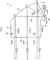
- Fig. 1 is a vertically-sectional view illustrating a configuration of a first embodiment of a lighting fixture for a vehicle according to the present invention.
- a lighting fixture 1 for a vehicle illustrated in Fig. 1 is applied to, for example, a headlamp performing irradiation of an illumination light having a light distribution pattern for a passing beam (low beam) in an automobile, an automatic bicycle or the like, and includes a lens body 10 (light guide) injection-molded with a polycarbonate material which is a transparent resin with a high heat resistance and an LED light source 30.
- the lens body 10 is formed in, for example, a three-dimensional shape enclosed by a bottom face 14 including an incident face 12, a reflecting face 16 arranged on a rear side of a vehicle (a rear side of a lighting fixture), an exit face 18 arranged on a front side of the vehicle, an upper face 20 arranged on an upper side of the vehicle, and two lateral faces (not illustrated) arranged on both lateral sides of the vehicle.
- the incident face 12 is an incident face through which light emitted from the LED light source 30 enters the lens body 10, and is formed of a flat face inclined relative to a horizontal direction (in a longitudinal direction of the vehicle).
- Other faces constituting the bottom face 14 are composed of horizontal flat faces.
- the reflecting face 16 reflects light which is emitted from the LED light source 30 to pass through the incident face 12 and to enter the lens body 10 in a predetermined direction.
- the reflecting face 16 is formed, for example, based upon the shape of a paraboloid of revolution type.
- the reflecting face 16 may be configured to totally reflect the incident light on an inner face thereof, or may be configured such that a reflecting film of a metal such as aluminum is formed on an outer face of the reflecting face 16 in a portion where the incident light is not totally reflected or the like so that the incident light is reflected by the reflecting film.
- the exit face 18 is a face through which the reflected light from the reflecting face 16 is emitted, and is formed of a flat face extending in a vertical direction perpendicular to the longitudinal direction of the vehicle in this embodiment.
- the LED light source 30 is, for example, a light source obtained by packaging one or a plurality of LED chips to emit white light, where a flat-shaped light emitting face 30A which is configured to emit light and is arranged upward in the substantially vertical direction.
- a flat-shaped light emitting face 30A which is configured to emit light and is arranged upward in the substantially vertical direction.
- an LED chip of InGaN series for emitting blue light is used as the LED chip
- a wavelength-converting material layer 204 is provided on a LED chip 200 mounted on a circuit base board 202 in a planer state can be used as the LED chip, as illustrated in Fig. 6A and 6B .
- the wavelength-converting material layer 204 one where YAG (Yttrium Aluminum Garnet) fluorescence substances have been dispersed in a silicone resin, or the like is used.
- the light emitting face 30A is not limited to a flat shape but may be formed in a convex shape.
- the lighting fixture 1 for a vehicle configured above is configured to emit light emitted from the LED light source 30 as illumination light with a light distribution pattern for a passing beam such as illustrated in Fig. 2 through the lens body 10.
- a light distribution pattern for a passing beam such as illustrated in Fig. 2 through the lens body 10.
- FIG. 2 an H line illustrating an angle in a horizontal direction to a straightforward direction of the lighting fixture 1 for a vehicle and a V line illustrating an angle in a vertical direction are illustrated.
- the light distribution pattern illustrated in Fig. 2 includes a light distribution region P (regions P1 to P4 whose light intensity values lower in sequence) where light is emitted so as to be expanded to both left and right sides of the V line within an angle range oriented in a more downward direction than the H line.
- a boundary line between light and dark (cutoff line) CL representing a boundary between light and dark between a light region on which light is illuminated and a dark region on which light is not illuminated is formed on an upper end edge of the light distribution region P so as to extend in a horizontal direction, and the boundary line CL between light and dark is formed in the vicinity of the H line (for example, a downward angle of 0.57°).
- the light distribution pattern P formed by the lighting fixture 1 for a vehicle of this embodiment is defined as a portion of the light distribution pattern illustrated in Fig. 2 (for example, any one of the regions P1 to P4).
- a plurality of lighting fixtures configured in the same manner as the lighting fixture 1 for a vehicle of this embodiment are arranged in a predetermined direction such as a tandem direction or a lateral direction, so that all of the lighting fixtures form the light distribution pattern illustrated in Fig. 2 .
- a positional relationship between the LED light source 30 and the lens body 10 and a targeted illumination direction of the respective white light beams is determined such that the light distribution pattern illustrated in Fig. 2 is formed.
- the shapes of the incident face 12, the reflecting face 16, and the exit face 18 of the lens body 10 are set such that respective white light beams emitted in the respective directions from the light emitting face 30A are coincident with targeted emitting directions.
- the reflecting face 16 of the paraboloid of revolution type is set such that a light emitting point 30B of the light emitting face 30A positioned at a rearmost end regarding the longitudinal direction of the vehicle is projected on the boundary line CL between light and dark in an expanded manner so that the cutoff line is formed.
- a light emitting point 30B of the light emitting face 30A positioned at a rearmost end regarding the longitudinal direction of the vehicle is projected on the boundary line CL between light and dark in an expanded manner so that the cutoff line is formed.
- a refraction index corresponding to a material of the lens body 10 is used, and when the refraction index varies according to the wavelength of light, a refraction index to a specific reference wavelength (hereinafter, called reference refraction index) is approximately-used as a fixed refraction index in the whole wavelength region of the white light beams (a visible light region).
- the optical design of the shapes of the incident face 12, the reflecting face 16, and the exit face 18 of the lens body 10 or the like is performed such that the light distribution pattern such as illustrated in Fig. 2 is obtained.
- the lens body 10 when the lens body 10 is formed of a transparent resin material like this embodiment, a difference in refraction index between respective wavelengths of light is larger than that of a glass lens made of inorganic material.
- the lens body 10 is formed of a polycarbonate material especially excellent in transparency, heat resistance, and weather resistance, the polycarbonate material is large in refraction index between respective wavelengths of light and is large in chromatic dispersion, so that when the optical design is performed such that a light distribution pattern such as illustrated in Fig.
- the chromatic dispersion means dispersion of light and means a phenomenon where when light enters a lens or the like, a refraction index varies according to the wavelength of the light.
- the above lens body 10 basically forms a light distribution pattern (or a portion of the light distribution pattern) as illustrated in Fig. 2 by projecting the light emitting face 30A of the LED light source 30 in an expanded state. Therefore, when the optical design is performed such that the light distribution pattern such as illustrated in Fig. 2 can be obtained assuming a fixed reference refraction index to the whole wavelength region of the white light beams and without considering the chromatic dispersion of the lens body 10, the positional relationship between the light emitting face 30A of the LED light source 30 and the lens body 10 is determined such that the light emitting point 30B of the light emitting face 30A which is the rearmost end regarding the longitudinal direction of the vehicle is positioned at a focus of the whole lens body 10.
- the focus of the whole lens body 10 means a focus position which has been adjusted considering influence due to refraction caused by the incident face 12 regarding the focus position of the reflecting face 16 of the paraboloid of revolution type.
- white light beams emitted from the light emitting point 30B in respective directions are emitted as light beams substantially parallel to the angle direction of the boundary line CL between light and dark which is a design target.
- Design is performed such that white light beams emitted from respective points on the light emitting face 30A which are positioned on a side ahead of the light emitting point 30B in the longitudinal direction of the vehicle are emitted within an angle range below the boundary line CL between light and dark which is the design target.
- light beams having wavelengths other than the light beam with a green wavelength (green light beam) used as the reference refraction index namely, red or blue light beams on the side of wavelengths longer than or shorter than the green wavelength are separated in different directions from the direction of the green light beam on a face at which refraction is caused by the lens body 10 because actual refraction indexes of the wavelengths of the red light beam and the blue light beam are different from the reference refraction index.
- portions of the red and blue light beams are emitted in a more upward angle direction than the boundary line CL between light and dark which is the design target so that chromatic aberration (color smear) is caused above the boundary line CL between light and dark to form an unintended illumination region Q as illustrated in Fig. 3 above the boundary line CL between light and dark.
- the configuration of the lens body 10, or the like (the shapes of the incident face 12, the reflecting face 16 and the exit face 18, or the like)
- adjustment (correction) to the shapes of the incident face 12, the reflecting face 16, and the exit face 18 of the lens body 10 is performed such that a chromatic aberration (an unintended illumination region Q) does not occur on the upper side of the boundary line CL between light and dark
- the chromatic dispersion (a difference between respective wavelengths) about white light beams emitted from the light emitting point 30B on the light emitting face 30A as described below.
- the polycarbonate material has such a characteristic that the refraction index of the polycarbonate material becomes smaller as the wavelength becomes longer in a range of about 380 to 780 nm which is the wavelength region of white light beams (the wavelength region of a visible light).
- the refraction index of the polycarbonate material to the blue wavelength of 435. 8 nm is 1.6115
- the refraction index of the polycarbonate material to the green wavelength of 546.1 nm is 1.5855
- the refraction index of the polycarbonate material to the blue wavelength of 706. 5 nm is 1.576.
- the reflecting face 16, and the exit face 18 of the lens body 10 for example, green light (wavelength of 546.1 nm) is used as the light with the reference wavelength, and the reference refraction index is set to 1.5855. Further, it is assumed that adjustment to the basic shapes of the incident face 12, the reflecting face 16, and the exit face 18 of the lens body 10 is performed such that the longest wavelength is set, for example, as the above wavelength (706.5 nm) of the red light and the shortest wavelength is set, for example, as the above wavelength (435.8 nm) of the blue light within the wavelength range of light to be considered regarding the problem of the chromatic dispersion of the lens body 10.
- lights described by designating the colors of the lights like the green light beam, the red light beam, and the blue light beam illustrate lights with the wavelengths listed above. However, values of the respective wavelengths illustrated specifically can be changed properly.
- adjustment to the basic shapes of the incident face 12, the reflecting face 16, and the exit face 18 of the lens body 10 has been performed by only adjustment of the reflecting face 12. That is, the respective shapes of the incident face 16 and the exit face 18 have been fixed to face shapes (flat faces) when designing has been performed such that the light distribution pattern illustrated in Fig. 2 is obtained assuming the reference refraction index, and, for example, adjustment to the paraboloid of revolution type obtained as the basic shape is performed regarding the reflecting face 16.
- the exit face 18 of the lens body 10 of the embodiment is formed by a flat face extending in the vertical direction, as described above. Because light reflected from the reflecting face 16 to the vicinity of the boundary line CL between light and dark is emitted in a substantially horizontal direction, the refraction caused by the exit face 18 is small, where the magnitude of the chromatic dispersion also becomes small. Therefore, for simplification of explanation, it is assumed that the chromatic dispersion and the color separation do not occur by the exit face 18, and it is also assumed that the direction of the light beam emitted from the exit face 18 is equal to the direction of the light beam reflected by the reflecting face 16.
- the shape adjustment of the lens body 10 will be described below.
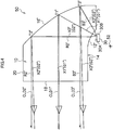
- the lens body 10 illustrated in Fig. 1 is obtained by applying adjustment (correction) to the shape of the reflecting face 16 of the lens body 10 considering the chromatic dispersion (a difference in refraction index between the respective wavelengths) such that an unintended illumination region Q does not occur on the upper side of the boundary line CL between light and dark, and optical paths at the reference refraction index (optical paths when the refraction index is a fixed basic refraction index within the whole wavelength region of the white light beams) of a white light beam X1 entering the incident face 12 perpendicularly to the incident face 12 (an entering angle 0°) and of white light beams X2 and X3 entering the incident face 12 obliquely on the front side of the vehicle and the rear side of the vehicle regarding the white light beam X1, of white light beams emitted from the light emitting point 30B positioned at the rearmost end of the LED light source 30 are illustrated with solid lines in Fig.
- the optical paths CLD1, CLD2 and CLD3 can be obtained by forming, as the reflecting face 16, a reflecting face of paraboloid of revolution having a position of the light emitting point 30B (strictly speaking, a position located slightly in a left lower direction on the figure from 30B considering refraction caused by the incident face 12) as a focus.
- This shape is defined as the basic shape.
- the optical paths CLD1, CLD2 and CLD3 illustrated by the dashed-dotted line represent optical paths for emitting the white light beams X1, X2, and X3 from the exit face 18 in the angle direction of the boundary line CL between light and dark which is the design target, and since the light beam emitted in a direction of the vicinity of the boundary line CL between light and dark is not refracted on the exit face 18, as described above, the optical paths CLD1, CLD2, and CLD 3 are illustrated as straight lines from the position of the reflecting face 16 to the outside of the lens body 10 via the exit face 18.
- the shape of the reflecting face 16 is set considering the chromatic dispersion. That is, regarding the white light beam X1 which enters the incident face 12 perpendicularly to the incident face 12 and does not cause refraction on the incident face 12 and the exit face 18 of the lens body 10, a target emitting direction is set in the angle direction of the boundary line CL between light and dark which is the design target without performing modification from the above. As illustrated in Fig.
- formation is performed such that the shape (a position and an inclination) of the reflecting face 16 at a position T1 coincides with the basic shape in such a manner that the white light beam X1 entering the position T1 on the reflecting face 16 is reflected in the angle direction of the boundary line CL between light and dark along the optical path CLD1.
- the angle of the incident face 12 is set such that the position T1 on the reflecting face 16 at which the white light beam X1 which does not cause refraction on the incident face 12 is reflected is at a substantially central position of the reflecting face 16 within a vertical range of the reflecting face 16.
- the position T1 is a reflecting portion of a non-refraction optical path where refraction does not occur on the incident face 12 and coincides with the above-described basic shape.
- target illumination directions are set in a more downward angle direction than the boundary line CL between light and dark according to magnitudes of the chromatic dispersion (color separation) caused by refractions of the white light beams.
- a fixed reference refraction index is assumed to the whole wavelength region of the white light beams, as illustrated in Fig.
- the shape of the reflecting face 16 is designed such that irradiations (reflections) of the white light beams X2 and X3 (namely, the green light beams) which have entered at the positions T2 and T3 positioned above and below the position T1 on the reflecting face 16 are performed in a more downward angle direction than the angle direction of the boundary line CL between light and dark (the optical paths CLD2 and CLD3).
- the method for designing the reflecting face 16 of this embodiment by correcting the reflecting face having the basic shape for example, it is assumed that using the position T1 where correction is not performed to the reflecting face having the basic shape as a reference point, points on the reflecting face positioned above the reference point are sequentially set as correction points. At a certain correction point, correction is made such that the inclination of the reflecting face 16 reaches an inclination so as to reflect the white light beam which has entered the certain correction point in a target illumination direction corrected, and the positions and the inclinations of the respective points on the whole reflecting face positioned above the correction point are corrected by adding rotation corresponding to the correction of the inclination to a whole portion of the reflecting face positioned above the correction point without changing the whole shape of the reflecting face.
- the shape of the reflecting face 16 is designed considering the chromatic dispersion like the lens body 10 of the embodiment, how irradiations of the white light beams X1, X2, and X3 emitted from the light emitting point 30B of the LED light source 30 are actually performed through the lens body 10 will be described specifically.
- the white light beam X1 entering the incident face 12 perpendicularly to the incident face 12 is not refracted on the incident face 12, the white light beam X1 advances in the lens body 10 as it is without causing chromatic dispersion (color separation) to enter the position T1 on the reflecting face 16. Then, the white light beam X1 which has entered the reflecting face 16 is reflected in a direction extending along the optical path CLD1 and irradiation of the white light beam X1 is performed in the angle direction of the boundary line CL between light and dark which is the design target (emitted from the exit face 18).
- a green light beam G1 contained in the white light beam X1 passes through the same optical path as the white light beam X1 illustrated in Fig. 1 to be emitted in the angle direction of the boundary line CL between light and dark which is the design target.
- the white light beam X1 emitted from the light emitting point 30B and entering the incident face 12 perpendicularly to the incident face 12 is emitted, while its color remains in white, in the angle direction of the boundary line CL between light and dark which is the design target, so that the white light beam X1 forms a white boundary line CL between light and dark.
- the white light beam X2 entering the incident face 12 obliquely from the front side of the vehicle enters the incident face 12 causes refraction and causes color separation within the lens body 10 due to chromatic dispersion.
- a green light beam G2 contained in the white light beam X2 advances in the same optical path as the white light beam X2 when the fixed reference refraction index is assumed to enter the position T2 on the reflecting face 16 within the lens body 10. Then, it is reflected in a more downward angle direction than the optical path CLD2 by the reflecting face 16, and it is emitted in a more downward angle direction than the angle direction of the boundary line CL between light and dark which is the design target.
- the red light beam R2 (a dotted line) contained in the white light beam X2 has a refraction index smaller than the reference refraction index (the refraction index of the green wavelength)
- the red light beam R2 is refracted on the incident face 12 at a refraction angle smaller than that of the green light beam G2, and advances in an optical path having an angle direction positioned nearer the front side of the vehicle than the optical path of the white light beam X2 (the optical path of the green light beam G2) to enter the vicinity of (above) the position T2 on the reflecting face 16.
- the red light beam R2 becomes larger in an incident angle to the reflecting face 16 than the white light beam X2 (the green light beam G2), the red light beam R2 is reflected in a more upward angle direction than the white light beam X2 (the green light beam G2).
- the target emitting direction of the white light beam X2 (the green light beam G2) is set and the shape of the reflecting face 16 is set such that the red light beam R2 is not emitted in a more upward angle direction than the boundary line CL between light and dark which is the design target, so that the red light beam R2 is reflected on the reflecting face 16 in an angle direction substantially extending along the optical path CLD2 or in a more downward angle direction than the optical path CLD2.
- the red light beam R2 is emitted from the exit face 18 so as not to be oriented in a more upward angle direction than the boundary line CL between light and dark which is the design target.
- a blue light beam (not illustrated) contained in the white light beam X2 is separated on the incident face 12 to pass through an optical path different from the white light beam X2 (the green light beam G2) illustrated in Fig. 1 .
- the blue light beam is emitted from the exit face 18 in a more downward angle direction than the white light beam X2 (the green light beam G2) in contradiction to the red light beam R2
- the red light beam R2 is emitted in an angle direction in which the red light beam R2 is not oriented in a more upward angle direction than the boundary line CL between light and dark which is the design target
- the blue light beam is necessarily emitted in an angle direction in which the blue light beam is not oriented in a more upward angle direction than the boundary line CL between light and dark which is the design target.
- the white light beam X3 entering the incident face 12 obliquely from the rear side of the vehicle enters the incident face 12 causes refraction and causes color separation within the lens body 10 due to chromatic dispersion.
- a green light beam G3 contained in the white light beam X3 advances in the same optical path as the white light beam X3 when a fixed reference refraction index is assumed in the lens body 10 to enter the position T3 on the reflecting face 16.
- the green light beam G3 is reflected in a more downward angle direction than the optical path CLD3 by the reflecting face 16 so that the green light beam G3 is emitted in a more downward angle direction than the angle direction of the boundary line CL between light and dark which is the design target.
- the blue light beam B3 (a dotted line) contained in the white light beam X3 has a larger refraction index than the reference refraction index (the refraction index of the green wavelength)
- the blue light beam B3 is refracted on the incident face 12 at a larger refraction angle than that of the green light beam G3 and advances in an optical path having an angle direction positioned nearer the front side of the vehicle than the optical path of the white light beam X3 (the optical path of the green light beam G3) to enter the vicinity of (above) the position T3 on the reflecting face 16.
- the blue light beam B3 is larger in incident angle to the reflecting face 16 than the white light beam X3 (the green light beam G3), the blue light beam B3 is reflected at a more upward angle direction than the white light beam X3 (the green light beam G3).
- the target emitting direction of the white light beam X3 (the green light beam G3) is set and the shape of the reflecting face 16 is set such that the blue light beam B3 is not emitted in a more upward angle direction than the boundary line CL between light and dark which is the design target.
- the blue light beam B3 is reflected on the reflecting face 16 in an angle direction substantially extending along the optical path CLD3 or in a more downward angle direction than the optical path CLD3.
- the blue light beam B3 is emitted from the exit face 18 so as not to be oriented in a more upward angle direction than the boundary line CL between light and dark which is the design target.
- a red light beam (not illustrated) contained in the white light beam X3 is separated on the incident face 12 to pass through an optical path different from the white light beam X3 (the green light beam G3) illustrated in Fig. 1 . Then, the red light beam is emitted from the exit face 18 in a more downward angle direction than the white light beam X3 (the green light beam G3) in contradiction to the blue light beam B3.
- the red light beam is also necessarily emitted in an angle direction in which the red light beam is not oriented in a more upward angle direction than the boundary line CL between light and dark which is the design target.
- the lighting fixture 1 for a vehicle of the embodiment regarding a light beam such as the white light beam X1, which passes through an optical path where the refraction does not occur and the chromatic dispersion (color separation) does not occur in the lens body 10, of the white light beams emitted in the respective directions from the light emitting point 30B of the LED light source 30, the light beam is emitted in the angle direction of the boundary line CL between light and dark, so that a clear boundary line CL between light and dark is formed by the white light. Further, the chromaticity of the boundary line CL between light and dark is held within a range of the white by formation of the boundary line CL between light and dark by the white light beam X1.
- the target emitting direction (the emitting direction of the green light beam) when a fixed reference refraction index is assumed over the whole wavelength region of the white light beams is set in a more downward angle direction than the boundary line CL between light and dark.
- the red or blue light beam which is emitted in a more upward angle direction than the green light beam due to chromatic dispersion is emitted in a more downward angle direction than the boundary line CL between light and dark. That is, light within a wavelength region which has been subjected to color separation is emitted within the light distribution pattern positioned below the boundary line CL between light and dark.
- the light is color-mixed with illumination light from positions other than the light emitting point 30B or the like within the light distribution. Accordingly, such a drawback that an unintended illumination region Q is generated on the upper side of the boundary line CL between light and dark due to chromatic dispersion is prevented.
- an end portion of the LED light source is utilized as a boundary between light and dark, especially, a boundary line CL between light and dark in the vicinity of the H line of a headlamp for a passing beam.
- the LED light source is provided with a wavelength-converting material layer extending up to an LED end portion, as illustrated in Figs.
- a color unevenness occurs at an LED light source end portion more easily than at a central portion of the LED light source. This involves such a potential problem that the color unevenness of the LED light source is projected on the boundary line CL between light and dark as it is when the LED light source is projected by the lens body in a magnified manner.
- the lens body manufactured considering the chromatic dispersion regarding the boundary line CL between light and dark is used, even if color unevenness has occurred at an end portion of the LED light source, it becomes possible to reduce the color unevenness.
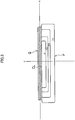
- Fig. 4 is a vertically-sectional view illustrating a configuration of a second embodiment of a lighting fixture for a vehicle according to the present invention. Elements identical with or similar to those of the lighting fixture 1 for a vehicle of the first embodiment illustrated in Fig. 1 are attached with identical or prime reference signs.
- a lighting fixture 50 for a vehicle illustrated in Fig. 4 is different in shape of an incident face 12' from the lighting fixture 1 for a vehicle illustrated in Fig. 1 .
- the incident face 12' of the lighting fixture for a vehicle50 illustrated in Fig. 4 is not formed in a flat face but a concave face.
- the other constituent elements of the lighting fixture 50 for a vehicle illustrated in Fig. 4 are constituted in the same manner as those in the lighting fixture 1 for a vehicle of the first embodiment, and the shape of a reflecting face 16' of the lens body 10 is formed so as to form the light distribution pattern illustrated in Fig. 2 .
- the incident face 12' is, for example, formed in an arc shape having a center 52 at a position separated from the incident face 12' farther than the light emitting point 30B of the LED light source 30 in vertically-sectional view illustrated in Fig. 4 (an arc which is larger in radius of curvature than an arc having the light emitting point 30B of the LED light source 30 as a center of the arc). Further, the incident face 12' is formed of such an arc concave face that the center 52 of the arc of the incident face 12' is positioned on a straight line passing through the light emitting point 30B and the position T1' near the center of the reflecting face 16'.
- incident angles of light beams emitted from the light emitting point 30B in respective directions when the light beams enter the incident face 12' are wholly smaller than that of the case of the lighting fixture 1 for a vehicle of the first embodiment, and chromatic dispersion on the incident face 12' due to refraction becomes smaller.
- the shape of the reflecting face 16' is designed considering chromatic dispersion occurring in the lens body 10.
- a white light beam X1' which enters the incident face 12' perpendicularly to the incident face 12' and does not cause refraction on the incident face 12' and the exit face 18 of the lens body 1 0, of white light beams emitted in the respective directions from the light emitting point 30B, a target emitting direction is set in an angle direction of the boundary line CL between light and dark. As illustrated in Fig.
- the shape (a position and an inclination) of the reflecting face 16' at a position T1' is formed such that the white light beam X1' (a green light beam G1') which has entered the position T1' on the reflecting face 16' is reflected in an angle direction of the boundary line CL between light and dark extending along an optical path CLD1'.
- target emitting directions are set in a more downward angle direction than the boundary line CL between light and dark according to magnitudes of the chromatic dispersion (color separation) caused by refractions thereof.
- the shape of the reflecting face 16' is designed such that the white light beams X2' and X3' (green light beams G2' and G3') which have entered at the positions T2' and T3' positioned above and below the position T1' on the reflecting face 16' are emitted (reflected) in a more downward angle direction than the angle directions (optical paths CLD2' and CLD3') of the boundary line CL between light and dark.
- the illumination region Q can be more securely prevented from occurring on the upper side of the boundary line CL between light and dark. Further, since occurrence of the illumination region Q can be prevented substantially completely, the downward degree (the magnitude of the downward angle) of the emitting direction of the white light beam (the green light beam) can be made relatively small, so that change to be added to the shape of the reflecting face 16' can be reduced and influence of the other illumination region other than the boundary line CL between light and dark on the light distribution can be reduced.
- the incident face 12' may be formed in an elliptic arc in a vertical section instead of the arc, and if the incident face 12' has a concave curved face as viewed from the light emitting point 30B, an effect similar to the above can be obtained.
- the shape of the incident face 12' is formed in a spherical face having the light emitting point 30B as a central point of the incident face 12', an incident angle from the light emitting point 30B become 0°, so that refraction does not occur. Therefore, color separation due to the incident angle can be prevented from occurring.
- the concave curved face is designed such that the chromatic dispersion becomes small, while a balance between a capturing amount of light emitted from the light emitting face 30A and the size of the reflecting ace 16 is considered.
- the curvature of a portion of the incident face positioned near the reflecting face is made close to that of a spherical face having the light emitting point 30B as a central point of the spherical face, as illustrated in Fig. 4 .
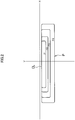
- Fig. 5 is a vertically-sectional view illustrating a configuration of a third embodiment of a lighting fixture for a vehicle according to the present invention. Elements identical with or similar to those of the lighting fixture for a vehicle of the first embodiment illustrated in Fig. 1 are attached with identical reference signs or double prime reference signs.
- a lighting fixture 100 for a vehicle illustrated in Fig. 5 is different from the lighting fixture for a vehicle illustrated in Fig. 1 in a configuration where light emitting from the LED light source 30 is guided up to a reflecting face 16" corresponding to the reflecting face 16 illustrated in Fig.
- the incident face 12" is formed on a back side (on the rear side of the vehicle) of the lens body 10 and the LED light source 30 is arranged on the back face side of the lens body 10 such that the light emitting face 30A faces the front side of the vehicle.
- the reflecting face 102 reflecting light in the lens body 10 is formed by performing vapor deposition of aluminum to an outer face portion of the lens body 10 where the reflecting face 102 is formed.
- such a drawback can be prevented that the illumination region Q due to chromatic dispersion is generated on the upper side of the boundary line CL between light and dark.
- the shape of the reflecting face 16" is designed considering chromatic dispersion occurring in the lens body 10.
- a white light beam X1 which enters the incident face 12" perpendicularly to the incident face 12" and does not cause refraction on the incident face 12" and the exit face 18 of the lens body 10, of white light beams emitted in respective directions from the light emitting point 30B
- a target emitting direction is set in an angle direction of the boundary line CL between light and dark. As illustrated in Fig.
- the shape (a position and an inclination) of the reflecting face 16" at the position T1" is formed such that the white light beam X1" (a green light beam G1") which has entered a position T1" on the reflecting face 16" is reflected in an angle direction of the boundary line CL between light and dark extending along an optical path CLD1".
- target emitting directions are set in a more downward angle direction than the boundary line CL between light and dark according to magnitudes of the chromatic dispersion (color separation) caused by refractions of the white light beams.
- the shape of the reflecting face 16" is designed such that the white light beams X2" and X3" (green light beams G2" and G3") which have entered at the positions T2" and T3" positioned above and below the position T1" on the reflecting face 16" are emitted (reflected) in a more downward angle direction than the angle direction of the boundary line CL between light and dark (optical paths CLD2" and CLD3").
- a selection range of the arrangement place of the LED light source 30 can be expanded. That is, by changing the positions of the incident face 12" and the reflecting face 102, it is made possible to change the arrangement place of the LED light source 30 to a position different from the position illustrated in Fig. 5 .
- the illumination region Q can be prevented from being generated on the upper side of the boundary line light and dark CL.
- the lens body 10 configured to reflect light which has entered the lens body 10 within the lens body 10 twice to emit the light from the exit face 18 is illustrated, but the illumination region Q can be prevented from occurring on the upper side of the boundary line CL between light and dark even in a lighting fixture for a vehicle using a lens body configured to reflect light which has entered the lens body 10 within the lens body 10 three times or more to emit the light from the exit face 18 in the same manner as the above embodiment.
- the lighting fixtures for a vehicle illustrated in the above first to third embodiments have the lens bodies 10 formed of the polycarbonate material, but even when the lens body 10 is formed of a material (for example, a transparent material such as glass or acrylic) other than the polycarbonate material, if the material is a material causing chromatic dispersion, the invention of the present application can be applied to the lens body 10 like the above embodiments. Thereby, an unintended illumination region Q can be prevented from being generated on the upper side of the boundary line between light and dark regardless of the magnitude of chromatic dispersion which can be generated for each material of the lens body 10.
- a material for example, a transparent material such as glass or acrylic
- the lighting fixture for a vehicle not only prevents generation of an unintended illumination region Q on the upper side of the boundary line between light and dark due to chromatic dispersion in the lens body 10 but also can reduce, in a case where the material of the lens body 10 has a property of birefringence like the polycarbonate material, blur of the boundary line between light and dark occurring due to the birefringence.
- the polycarbonate material is large in residual stress at a formation time thereof and has a property of birefringence due to high photoelastic coefficient specific to the material, where light beams (light beams refracted on the incident face 12), which enter the incident face 12 (12', 12") obliquely, of light beams emitted from the light emitting point 30B of the LED light source 30 are complexly separated in a plurality of directions. If designing is performed such that the white light beam (the green light beam) when a fixed reference refraction index is assumed is emitted in an angle direction of the boundary line CL between light and dark without considering birefringence to these light beams, the light beams separated due to the birefringence cause blur of the boundary line CL between light and dark.
- the shape of the reflecting face 16 (16') is corrected from the basic shape of the reflecting face 16 (16') such that an emitting direction of a green light beam (a white light beam when a fixed reference refraction index is assumed) passing through an optical path causing refraction is oriented in a more downward angle direction than the angle direction of the boundary line CL between light and dark, but such a configuration can be adopted that by correcting the shape of at least one face (either one or more faces) of the incident face 12 (12'), the reflecting face 16 (16'), and the exit face 18 (18') from the basic shape, the green light beam passing through the optical path causing refraction is oriented in a more downward angle direction than the angle direction of the boundary line CL between light and dark.
- the exit face 18 of the lens body 10 is formed as a flat face and such a condition is adopted that the light beam which is emitted from the reflecting face 16 in the angle direction of the vicinity of the boundary line CL between light and dark which is the design target is not refracted on the exit face 18, but the present invention can be applied to such a case that the exit face 18 is not a flat face (for example, a concave face or a convex face) and refraction occurs on the exit face 18.
- At least one optical path (non-refraction optical path) of a light beam which enters both the incident face 12 (12', 12") and the exit face 18 perpendicularly to the incident face 12 (12', 12") and the exit face 18 and does not cause refraction, of light beams exited from the light emitting point 30B of the LED light source 30 is provided, an emitting direction (an emission direction from the exit face 18) of a green light beam (the white light beam) passing through the at least one optical path (non-refraction optical path) is set in the direction of the boundary line CL between light and dark, and regarding an optical path (a refraction optical path) of a light beam, which is refracted on the incident face 12 (12') or the exit face 18, of the light beams emitted from the light emitting point 30B of the LED light source 30, an emitting direction of a green light beam (a white light beam when a fixed reference refraction index is assumed) is oriented in a
- an emitting direction of a green light beam (a white light beam when a fixed reference refraction index is assumed) is determined to coincide with a direction in which all lights positioned on the side of a wavelength longer or on the side of a wavelength shorter than the wavelength of the reference refraction index coincide with the angle direction of the boundary line CL between light and dark or in a more downward direction than the angle direction of the boundary line CL between light and dark, lights which are emitted in a more upward angle direction than the boundary line CL between light and dark can be completely eliminated, and occurrence of an unintended illumination region Q can be prevented completely.
- the position T1 (T1', T1") of the non-refraction optical path reflecting portion where a light beam passing through the non-refraction optical path is reflected on the reflecting face 16 (16', 16") is positioned substantially at the center of the reflecting face 16 in the vertical direction of the reflecting face 16, but the position T (T', T") may not is at the center necessarily.
- the shape of the upper side refraction optical path reflecting portion may be corrected to the basic shape such that only the emitting direction of the green light beam (the white light beam when a fixed reference refraction index is assumed) is oriented in a more downward angle direction than the angle direction of the boundary line CL between light and dark.
- the present invention is not limited to the headlamp.
- the present invention can also be applied to not only the headlamp for a passing beam but also another kind of lighting fixture for a vehicle such as a headlamp for a high beam or a fog lamp when the another kind of lighting fixture for a vehicle is a lighting fixture for a vehicle forming a light distribution pattern having a boundary between light and dark at an end edge of the light distribution pattern or a lighting fixture for a vehicle performing irradiation of an illumination light in a direction of a boundary between light and dark in a portion of the light distribution pattern.
Claims (5)
- Beleuchtungsanbringung (1, 50, 100) für ein Fahrzeug, die Folgendes aufweist:eine Lichtquelle (30), die konfiguriert ist, um ein sichtbares Licht mit einer Vielzahl von Wellenlängenkomponenten zu emittieren; undeinen Linsenkörper (10), der eine Einfallsfläche (12, 12', 12"), eine reflektierende Fläche (16, 16', 16", 102) und eine Austrittsfläche (18) aufweist, wobei der Linsenkörper (10) konfiguriert ist, um das Licht von der Lichtquelle (30) zu reflektieren, welches durch die Eintrittsfläche (12, 12', 12") hindurchgegangen ist, um in den Linsenkörper (10) in einer vorbestimmten Richtung durch die reflektierende Fläche (16, 16', 16", 102) einzutreten, um das Licht von der Austrittsfläche (18) aus dem Linsenkörper (10) zu emittieren,dadurch gekennzeichnet, dassdie Formen der Eintrittsfläche (12, 12', 12"), der reflektierende Fläche (16, 16', 16", 102) und der Austrittsfläche (18) so konfiguriert sind, dass Licht mit einer grünen Wellenlänge (G1), welches in Licht in einem sichtbaren Bereich (X1, X2, X3) enthalten ist, welches von einem Endteil der Lichtquelle (30) emittiert worden ist, um in die Eintrittsfläche (12, 12', 12") einzutreten, von der Austrittsfläche (18) in einer Richtung einer Grenzlinie (CL) zwischen Licht und Dunkel eines vorbestimmten Lichtverteilungsmusters emittiert wird, und so konfiguriert sind, dass Licht mit der grünen Wellenlänge (G1) bei einer im Wesentlichen zentralen Position der reflektierenden Fläche (16, 16', 16", 102) in einer vertikalen Richtung der reflektierenden Fläche (16, 16', 16", 102) reflektiert wird und durch einen nicht brechenden, optischen Pfad hindurchgeht, in dem keine Brechung auf der Eintrittsfläche (12, 12', 12") und der Austrittsfläche (18) stattfindet, undLichter (G2, G3), welche bei einer oberen Seitenposition (T2) und einer unteren Seitenposition (T3) auf der reflektierenden Fläche (16, 16', 16", 102) oberhalb und unterhalb des Lichts (X1, G1) des nicht-brechenden, optischen Pfads (T1) reflektiert werden, durch einen optischen Brechungspfad hindurchgehen, in dem eine Brechung auf der Einfallsfläche (12, 12', 12") oder der Austrittsfläche (18) stattfindet; undzumindest eine Fläche der Eintrittsfläche (12, 12', 12") und/oder der reflektierenden Fläche (16, 16', 16", 102) und/oder der Austrittsfläche (18) des Linsenkörpers (10) eine Form aufweist, die korrigiert ist,a) so dass das Licht mit einer grünen Wellenlängenkomponente (G2, G3), welches durch den optischen Brechungspfad (T2, T3) hindurchgeht, unterhalb der Richtung der Grenzlinie (CL) zwischen Licht und Dunkel hindurchgeht, undb) so dass das Licht, welches eine andere Wellenlängenkomponente als die grüne Wellenlängenkomponente (R2, B3), die einer chromatischen Dispersion durch Brechung unterworfen worden ist, aufweist, von dem Licht, das durch den optischen Brechungspfad (T2, T3) hindurchgeht, nicht über die Grenzlinie (CL) zwischen Licht und Dunkel verteilt wird.
- Beleuchtungsanbringung für ein Fahrzeug gemäß Anspruch 1, wobei die Einfallsfläche (12') eine konkav gekrümmte Fläche ist, die einen Bogen bildet, dessen Querschnittsform eine Mitte der Einfallsfläche (12') bei einer Position aufweist, die von dem Endteil der Lichtquelle (30) getrennt ist, oder einen elliptischen Bogen.
- Beleuchtungsanbringung für ein Fahrzeug gemäß Anspruch 2, wobei der Linsenkörper (10) eine zweite reflektierende Fläche (102) aufweist, die sich von der reflektierenden Fläche (16") unterscheidet; und
die zweite reflektierende Fläche (102) in einem optischen Pfad vorgesehen ist, wo Licht, das von der Eintrittsfläche (12") eingetreten ist, sich in dem Linsenkörper (10) vorwärts bewegt, so dass es die reflektierende Fläche (16") erreicht. - Beleuchtungsanbringung für ein Fahrzeug gemäß einem der Ansprüche 1 bis 3, wobei die Lichtquelle (30) eine LED-Lichtquelle ist, die ein Leuchtdiodenelement (200) und ein Wellenlängenumwandlungsmaterial (204) enthält.
- Beleuchtungsanbringung für ein Fahrzeug gemäß einem der Ansprüche 1 bis 4, wobei der Linsenkörper (10) aus einem Polycarbonatmaterial gebildet ist.
Applications Claiming Priority (2)
| Application Number | Priority Date | Filing Date | Title |
|---|---|---|---|
| JP2009204822A JP5445923B2 (ja) | 2009-09-04 | 2009-09-04 | 車両用灯具 |
| PCT/JP2010/064487 WO2011027708A1 (ja) | 2009-09-04 | 2010-08-26 | 車両用灯具 |
Publications (3)
| Publication Number | Publication Date |
|---|---|
| EP2474779A1 EP2474779A1 (de) | 2012-07-11 |
| EP2474779A4 EP2474779A4 (de) | 2015-09-09 |
| EP2474779B1 true EP2474779B1 (de) | 2018-10-10 |
Family
ID=43649246
Family Applications (1)
| Application Number | Title | Priority Date | Filing Date |
|---|---|---|---|
| EP10813657.3A Active EP2474779B1 (de) | 2009-09-04 | 2010-08-26 | Fahrzeuglampenarmatur |
Country Status (6)
| Country | Link |
|---|---|
| US (1) | US8702287B2 (de) |
| EP (1) | EP2474779B1 (de) |
| JP (1) | JP5445923B2 (de) |
| KR (1) | KR101772238B1 (de) |
| CN (1) | CN102483209B (de) |
| WO (1) | WO2011027708A1 (de) |
Families Citing this family (41)
| Publication number | Priority date | Publication date | Assignee | Title |
|---|---|---|---|---|
| JP5562120B2 (ja) * | 2010-05-21 | 2014-07-30 | スタンレー電気株式会社 | 車両用灯具ユニット |
| JP5707661B2 (ja) * | 2011-03-25 | 2015-04-30 | スタンレー電気株式会社 | 車両用灯具ユニット及び車両用灯具に用いられる導光体 |
| JP5919685B2 (ja) * | 2011-08-31 | 2016-05-18 | 市光工業株式会社 | 車両用前照灯 |
| DE102012209172A1 (de) * | 2012-05-31 | 2013-12-05 | Osram Gmbh | Linse mit innenreflektierender Reflexionslage |
| DE102012218179A1 (de) * | 2012-10-05 | 2014-04-10 | Osram Gmbh | Vorrichtung zur Strahlformung von Licht |
| DE102012218684B9 (de) * | 2012-10-12 | 2016-05-25 | Automotive Lighting Reutlingen Gmbh | Lichtmodul |
| DE102013013995B4 (de) * | 2013-01-23 | 2023-06-07 | Docter Optics Se | Scheinwerferlinse für einen Fahrzeugscheinwerfer |
| US9222637B2 (en) * | 2013-03-14 | 2015-12-29 | Valeo North America, Inc. | Lightguide with horizontal cutoff and horizontal spread |
| JP6409259B2 (ja) * | 2013-09-05 | 2018-10-24 | 市光工業株式会社 | 車両用灯具 |
| DE102013220192B4 (de) * | 2013-10-07 | 2015-04-30 | Automotive Lighting Reutlingen Gmbh | LED-Modul eines Kraftfahrzeugscheinwerfers |
| CN104654119A (zh) * | 2013-11-25 | 2015-05-27 | 上海航空电器有限公司 | 二次配光的大角度入射led照明灯具 |
| CN103759202A (zh) * | 2013-12-09 | 2014-04-30 | 广东雪莱特光电科技股份有限公司 | 一种车用前照灯的照明结构和散热结构 |
| FR3019264B1 (fr) * | 2014-03-31 | 2019-04-05 | Morpho | Optique d'eclairage |
| WO2015178155A1 (ja) | 2014-05-23 | 2015-11-26 | スタンレー電気株式会社 | レンズ体、レンズ結合体及び車両用灯具 |
| KR102243936B1 (ko) * | 2014-07-04 | 2021-04-23 | 에스엘 주식회사 | 차량용 램프의 렌즈 및 이를 이용한 차량용 램프 |
| FR3023600B1 (fr) * | 2014-07-11 | 2021-04-16 | Valeo Vision | Module lumineux d'un vehicule automobile |
| JP6081519B2 (ja) * | 2014-08-27 | 2017-02-15 | 三菱電機株式会社 | 前照灯モジュール及び前照灯 |
| DE102014226647A1 (de) * | 2014-12-19 | 2016-06-23 | Osram Gmbh | LED-Träger mit einer LED und Leuchte mit einem derartigen LED-Träger |
| CN104633572B (zh) * | 2014-12-27 | 2017-08-25 | 长城汽车股份有限公司 | 光线处理装置和车灯以及车辆 |
| KR102289727B1 (ko) * | 2015-05-22 | 2021-08-13 | 에스엘 주식회사 | 차량용 헤드램프 |
| CN107735615B (zh) * | 2015-06-29 | 2021-02-09 | 株式会社小糸制作所 | 车辆用灯具 |
| EP3130842B1 (de) * | 2015-07-15 | 2019-09-25 | CoeLux S.r.l. | Lichtkuppelbeleuchtungssystem |
| CN107924062B (zh) * | 2015-09-05 | 2021-04-23 | 镭亚股份有限公司 | 双表面准直器以及使用它的采用基于光栅的背光照明的3d电子显示器 |
| DE102015015360A1 (de) * | 2015-11-27 | 2017-06-01 | GM Global Technology Operations LLC (n. d. Ges. d. Staates Delaware) | Scheinwerfer für ein Kraftfahrzeug |
| FR3048485B1 (fr) * | 2016-03-02 | 2019-04-05 | Valeo Vision | Lentille amelioree pour dispositif d'eclairage de vehicule automobile |
| CN108613125B (zh) * | 2016-12-23 | 2023-11-21 | 市光法雷奥(佛山)汽车照明系统有限公司 | 用于机动车辆的发光装置 |
| JP6818542B2 (ja) * | 2016-12-26 | 2021-01-20 | スタンレー電気株式会社 | レンズ保持構造、及び、車両用灯具 |
| CN107062119A (zh) * | 2017-01-09 | 2017-08-18 | 成都恒坤光电科技有限公司 | 一种出光透镜及双光车灯 |
| KR101906526B1 (ko) | 2017-02-03 | 2018-10-10 | 영남대학교 산학협력단 | 차량용 조명 장치의 일체형 광학계 |
| CN108916805B (zh) * | 2017-03-22 | 2021-03-30 | 堤维西交通工业股份有限公司 | 车灯透镜 |
| JP6840606B2 (ja) * | 2017-04-14 | 2021-03-10 | スタンレー電気株式会社 | レンズ体および車両用灯具 |
| DE102017109079B4 (de) | 2017-04-27 | 2024-02-22 | OSRAM Opto Semiconductors Gesellschaft mit beschränkter Haftung | Optoelektronisches Bauelement und Bauteil mit solch einem Bauelement |
| KR102439106B1 (ko) * | 2017-09-05 | 2022-09-05 | 현대자동차주식회사 | 차량의 리어 램프 장치 |
| CN107781781B (zh) * | 2017-11-21 | 2023-11-10 | 华域视觉科技(上海)有限公司 | 反射式聚光器、车灯及汽车 |
| JP6523417B2 (ja) * | 2017-12-07 | 2019-05-29 | スタンレー電気株式会社 | 車両用前照灯 |
| JP7047132B2 (ja) * | 2018-01-27 | 2022-04-04 | レイア、インコーポレイテッド | サブ波長格子を用いた偏光リサイクルバックライト、方法、およびマルチビューディスプレイ |
| DE102018127610A1 (de) * | 2018-11-06 | 2020-05-07 | HELLA GmbH & Co. KGaA | Verfahren zur Herstellung eines Optikbausteins, Optikbaustein sowie Abbildungseinheit |
| KR20200143576A (ko) * | 2019-06-13 | 2020-12-24 | 현대자동차주식회사 | 차량용 슬림형 램프장치 |
| CN211575020U (zh) * | 2019-12-04 | 2020-09-25 | 华域视觉科技(上海)有限公司 | 透镜及车灯照明系统 |
| JP7031087B1 (ja) * | 2021-05-12 | 2022-03-07 | 三菱電機株式会社 | 前照灯装置用光源分配素子、前照灯装置、及び前照灯モジュール |
| JP2024024516A (ja) * | 2022-08-09 | 2024-02-22 | 株式会社小糸製作所 | 光学部材および車両用灯具 |
Family Cites Families (19)
| Publication number | Priority date | Publication date | Assignee | Title |
|---|---|---|---|---|
| US3818210A (en) * | 1972-03-06 | 1974-06-18 | Westinghouse Electric Corp | Vehicular road-lighting system having a headlamp with a dual-segment reflector |
| DE3507013A1 (de) * | 1985-02-28 | 1986-08-28 | Robert Bosch Gmbh, 7000 Stuttgart | Scheinwerfer fuer abblendlicht oder nebellicht von kraftfahrzeugen |
| EP0221416B1 (de) * | 1985-11-07 | 1995-09-27 | Robert Bosch Gmbh | Scheinwerfer für Abblendlicht oder Nebellicht von Kraftfahrzeugen |
| CN2045813U (zh) * | 1988-12-17 | 1989-10-11 | 王志臣 | 双抛物面防眩目前灯 |
| JP2707391B2 (ja) * | 1992-09-01 | 1998-01-28 | 株式会社小糸製作所 | プロジェクタ型前照灯 |
| US5307247A (en) * | 1992-09-22 | 1994-04-26 | Autopal, Statni Podnik | Headlamp for motor vehicles |
| JPH0650107U (ja) * | 1992-12-10 | 1994-07-08 | 株式会社小糸製作所 | プロジェクタ型前照灯 |
| JP2002214563A (ja) | 2001-01-12 | 2002-07-31 | Mitsubishi Electric Corp | ランプ、偏光変換光学系、集光光学系および画像表示装置 |
| US6811289B2 (en) * | 2001-01-22 | 2004-11-02 | Ichikoh Industries, Ltd. | Lamp device for a vehicle having a free curved surface and a lens without a prism |
| JP4068387B2 (ja) * | 2002-04-23 | 2008-03-26 | 株式会社小糸製作所 | 光源ユニット |
| JP4138586B2 (ja) * | 2003-06-13 | 2008-08-27 | スタンレー電気株式会社 | 光源用ledランプおよびこれを用いた車両用前照灯 |
| JP4339143B2 (ja) | 2004-02-10 | 2009-10-07 | 株式会社小糸製作所 | 車両用灯具ユニット |
| KR100813959B1 (ko) * | 2004-10-19 | 2008-03-14 | 삼성전자주식회사 | 조명장치 |
| JP2006127856A (ja) * | 2004-10-27 | 2006-05-18 | Koito Mfg Co Ltd | 車両用照明灯具 |
| JP4468857B2 (ja) | 2005-05-17 | 2010-05-26 | 株式会社小糸製作所 | 車両用照明灯具 |
| JP4574573B2 (ja) * | 2006-03-14 | 2010-11-04 | 株式会社小糸製作所 | 車両用灯具ユニット |
| JP2007335311A (ja) * | 2006-06-16 | 2007-12-27 | Koito Mfg Co Ltd | 車輌用灯具 |
| JP4798784B2 (ja) | 2006-09-25 | 2011-10-19 | スタンレー電気株式会社 | 車両用灯具 |
| KR20080053712A (ko) * | 2006-12-11 | 2008-06-16 | 삼성전기주식회사 | Led 광원장치 |
-
2009
- 2009-09-04 JP JP2009204822A patent/JP5445923B2/ja active Active
-
2010
- 2010-08-26 KR KR1020127005793A patent/KR101772238B1/ko active IP Right Grant
- 2010-08-26 EP EP10813657.3A patent/EP2474779B1/de active Active
- 2010-08-26 WO PCT/JP2010/064487 patent/WO2011027708A1/ja active Application Filing
- 2010-08-26 CN CN201080039228.1A patent/CN102483209B/zh active Active
-
2012
- 2012-03-05 US US13/412,579 patent/US8702287B2/en active Active
Non-Patent Citations (1)
| Title |
|---|
| None * |
Also Published As
| Publication number | Publication date |
|---|---|
| CN102483209B (zh) | 2014-10-22 |
| US8702287B2 (en) | 2014-04-22 |
| KR20120056840A (ko) | 2012-06-04 |
| EP2474779A4 (de) | 2015-09-09 |
| CN102483209A (zh) | 2012-05-30 |
| EP2474779A1 (de) | 2012-07-11 |
| JP5445923B2 (ja) | 2014-03-19 |
| KR101772238B1 (ko) | 2017-09-12 |
| JP2011054527A (ja) | 2011-03-17 |
| WO2011027708A1 (ja) | 2011-03-10 |
| US20120176809A1 (en) | 2012-07-12 |
Similar Documents
| Publication | Publication Date | Title |
|---|---|---|
| EP2474779B1 (de) | Fahrzeuglampenarmatur | |
| JP5481764B2 (ja) | 車両用灯具 | |
| JP5516854B2 (ja) | 車両用灯具 | |
| JP6207874B2 (ja) | 車両用灯具の灯具ユニット | |
| US8690405B2 (en) | Vehicle lighting unit | |
| US9103519B2 (en) | Vehicle lighting unit | |
| EP2484964B1 (de) | Lampeneinheit | |
| CN102644895A (zh) | 车辆用灯具 | |
| US20130322105A1 (en) | Vehicular Lamp | |
| TWM540240U (zh) | 可消除色散的直射式led照明模組 | |
| JP6285193B2 (ja) | 車両用灯具 | |
| JP5445049B2 (ja) | 車両用灯具 | |
| JP2011070877A (ja) | 車両用灯具 | |
| EP2570715A2 (de) | Fahrzeugscheinwerfer | |
| JP6119279B2 (ja) | 車両用前照灯 | |
| JP5446757B2 (ja) | 車両用灯具 | |
| JP5397174B2 (ja) | 車両用灯具 | |
| JP2014175231A (ja) | 車両用灯具 | |
| KR102441948B1 (ko) | 차량용 램프 | |
| KR101959794B1 (ko) | 차량용 램프 | |
| KR20150134874A (ko) | 차량용 램프 |
Legal Events
| Date | Code | Title | Description |
|---|---|---|---|
| PUAI | Public reference made under article 153(3) epc to a published international application that has entered the european phase |
Free format text: ORIGINAL CODE: 0009012 |
|
| 17P | Request for examination filed |
Effective date: 20120302 |
|
| AK | Designated contracting states |
Kind code of ref document: A1 Designated state(s): AL AT BE BG CH CY CZ DE DK EE ES FI FR GB GR HR HU IE IS IT LI LT LU LV MC MK MT NL NO PL PT RO SE SI SK SM TR |
|
| DAX | Request for extension of the european patent (deleted) | ||
| RA4 | Supplementary search report drawn up and despatched (corrected) |
Effective date: 20150806 |
|
| RIC1 | Information provided on ipc code assigned before grant |
Ipc: F21Y 101/02 20060101ALI20150731BHEP Ipc: F21W 101/10 20060101ALI20150731BHEP Ipc: F21S 8/10 20060101AFI20150731BHEP |
|
| REG | Reference to a national code |
Ref country code: DE Ref legal event code: R079 Ref document number: 602010054277 Country of ref document: DE Free format text: PREVIOUS MAIN CLASS: F21S0008100000 Ipc: F21S0041100000 |
|
| GRAP | Despatch of communication of intention to grant a patent |
Free format text: ORIGINAL CODE: EPIDOSNIGR1 |
|
| STAA | Information on the status of an ep patent application or granted ep patent |
Free format text: STATUS: GRANT OF PATENT IS INTENDED |
|
| RIC1 | Information provided on ipc code assigned before grant |
Ipc: F21S 41/10 20180101AFI20180228BHEP |
|
| INTG | Intention to grant announced |
Effective date: 20180329 |
|
| GRAS | Grant fee paid |
Free format text: ORIGINAL CODE: EPIDOSNIGR3 |
|
| GRAA | (expected) grant |
Free format text: ORIGINAL CODE: 0009210 |
|
| STAA | Information on the status of an ep patent application or granted ep patent |
Free format text: STATUS: THE PATENT HAS BEEN GRANTED |
|
| AK | Designated contracting states |
Kind code of ref document: B1 Designated state(s): AL AT BE BG CH CY CZ DE DK EE ES FI FR GB GR HR HU IE IS IT LI LT LU LV MC MK MT NL NO PL PT RO SE SI SK SM TR |
|
| REG | Reference to a national code |
Ref country code: GB Ref legal event code: FG4D |
|
| REG | Reference to a national code |
Ref country code: CH Ref legal event code: EP Ref country code: AT Ref legal event code: REF Ref document number: 1051664 Country of ref document: AT Kind code of ref document: T Effective date: 20181015 |
|
| REG | Reference to a national code |
Ref country code: IE Ref legal event code: FG4D |
|
| REG | Reference to a national code |
Ref country code: DE Ref legal event code: R096 Ref document number: 602010054277 Country of ref document: DE |
|
| REG | Reference to a national code |
Ref country code: NL Ref legal event code: MP Effective date: 20181010 |
|
| REG | Reference to a national code |
Ref country code: LT Ref legal event code: MG4D |
|
| REG | Reference to a national code |
Ref country code: AT Ref legal event code: MK05 Ref document number: 1051664 Country of ref document: AT Kind code of ref document: T Effective date: 20181010 |
|
| PG25 | Lapsed in a contracting state [announced via postgrant information from national office to epo] |
Ref country code: NL Free format text: LAPSE BECAUSE OF FAILURE TO SUBMIT A TRANSLATION OF THE DESCRIPTION OR TO PAY THE FEE WITHIN THE PRESCRIBED TIME-LIMIT Effective date: 20181010 |
|
| PG25 | Lapsed in a contracting state [announced via postgrant information from national office to epo] |
Ref country code: IS Free format text: LAPSE BECAUSE OF FAILURE TO SUBMIT A TRANSLATION OF THE DESCRIPTION OR TO PAY THE FEE WITHIN THE PRESCRIBED TIME-LIMIT Effective date: 20190210 Ref country code: FI Free format text: LAPSE BECAUSE OF FAILURE TO SUBMIT A TRANSLATION OF THE DESCRIPTION OR TO PAY THE FEE WITHIN THE PRESCRIBED TIME-LIMIT Effective date: 20181010 Ref country code: LT Free format text: LAPSE BECAUSE OF FAILURE TO SUBMIT A TRANSLATION OF THE DESCRIPTION OR TO PAY THE FEE WITHIN THE PRESCRIBED TIME-LIMIT Effective date: 20181010 Ref country code: PL Free format text: LAPSE BECAUSE OF FAILURE TO SUBMIT A TRANSLATION OF THE DESCRIPTION OR TO PAY THE FEE WITHIN THE PRESCRIBED TIME-LIMIT Effective date: 20181010 Ref country code: NO Free format text: LAPSE BECAUSE OF FAILURE TO SUBMIT A TRANSLATION OF THE DESCRIPTION OR TO PAY THE FEE WITHIN THE PRESCRIBED TIME-LIMIT Effective date: 20190110 Ref country code: HR Free format text: LAPSE BECAUSE OF FAILURE TO SUBMIT A TRANSLATION OF THE DESCRIPTION OR TO PAY THE FEE WITHIN THE PRESCRIBED TIME-LIMIT Effective date: 20181010 Ref country code: BG Free format text: LAPSE BECAUSE OF FAILURE TO SUBMIT A TRANSLATION OF THE DESCRIPTION OR TO PAY THE FEE WITHIN THE PRESCRIBED TIME-LIMIT Effective date: 20190110 Ref country code: ES Free format text: LAPSE BECAUSE OF FAILURE TO SUBMIT A TRANSLATION OF THE DESCRIPTION OR TO PAY THE FEE WITHIN THE PRESCRIBED TIME-LIMIT Effective date: 20181010 Ref country code: AT Free format text: LAPSE BECAUSE OF FAILURE TO SUBMIT A TRANSLATION OF THE DESCRIPTION OR TO PAY THE FEE WITHIN THE PRESCRIBED TIME-LIMIT Effective date: 20181010 Ref country code: LV Free format text: LAPSE BECAUSE OF FAILURE TO SUBMIT A TRANSLATION OF THE DESCRIPTION OR TO PAY THE FEE WITHIN THE PRESCRIBED TIME-LIMIT Effective date: 20181010 |
|
| PG25 | Lapsed in a contracting state [announced via postgrant information from national office to epo] |
Ref country code: PT Free format text: LAPSE BECAUSE OF FAILURE TO SUBMIT A TRANSLATION OF THE DESCRIPTION OR TO PAY THE FEE WITHIN THE PRESCRIBED TIME-LIMIT Effective date: 20190210 Ref country code: AL Free format text: LAPSE BECAUSE OF FAILURE TO SUBMIT A TRANSLATION OF THE DESCRIPTION OR TO PAY THE FEE WITHIN THE PRESCRIBED TIME-LIMIT Effective date: 20181010 Ref country code: SE Free format text: LAPSE BECAUSE OF FAILURE TO SUBMIT A TRANSLATION OF THE DESCRIPTION OR TO PAY THE FEE WITHIN THE PRESCRIBED TIME-LIMIT Effective date: 20181010 Ref country code: GR Free format text: LAPSE BECAUSE OF FAILURE TO SUBMIT A TRANSLATION OF THE DESCRIPTION OR TO PAY THE FEE WITHIN THE PRESCRIBED TIME-LIMIT Effective date: 20190111 |
|
| REG | Reference to a national code |
Ref country code: DE Ref legal event code: R097 Ref document number: 602010054277 Country of ref document: DE |
|
| PG25 | Lapsed in a contracting state [announced via postgrant information from national office to epo] |
Ref country code: IT Free format text: LAPSE BECAUSE OF FAILURE TO SUBMIT A TRANSLATION OF THE DESCRIPTION OR TO PAY THE FEE WITHIN THE PRESCRIBED TIME-LIMIT Effective date: 20181010 Ref country code: CZ Free format text: LAPSE BECAUSE OF FAILURE TO SUBMIT A TRANSLATION OF THE DESCRIPTION OR TO PAY THE FEE WITHIN THE PRESCRIBED TIME-LIMIT Effective date: 20181010 Ref country code: DK Free format text: LAPSE BECAUSE OF FAILURE TO SUBMIT A TRANSLATION OF THE DESCRIPTION OR TO PAY THE FEE WITHIN THE PRESCRIBED TIME-LIMIT Effective date: 20181010 |
|
| PLBE | No opposition filed within time limit |
Free format text: ORIGINAL CODE: 0009261 |
|
| STAA | Information on the status of an ep patent application or granted ep patent |
Free format text: STATUS: NO OPPOSITION FILED WITHIN TIME LIMIT |
|
| PG25 | Lapsed in a contracting state [announced via postgrant information from national office to epo] |
Ref country code: RO Free format text: LAPSE BECAUSE OF FAILURE TO SUBMIT A TRANSLATION OF THE DESCRIPTION OR TO PAY THE FEE WITHIN THE PRESCRIBED TIME-LIMIT Effective date: 20181010 Ref country code: SK Free format text: LAPSE BECAUSE OF FAILURE TO SUBMIT A TRANSLATION OF THE DESCRIPTION OR TO PAY THE FEE WITHIN THE PRESCRIBED TIME-LIMIT Effective date: 20181010 Ref country code: SM Free format text: LAPSE BECAUSE OF FAILURE TO SUBMIT A TRANSLATION OF THE DESCRIPTION OR TO PAY THE FEE WITHIN THE PRESCRIBED TIME-LIMIT Effective date: 20181010 Ref country code: EE Free format text: LAPSE BECAUSE OF FAILURE TO SUBMIT A TRANSLATION OF THE DESCRIPTION OR TO PAY THE FEE WITHIN THE PRESCRIBED TIME-LIMIT Effective date: 20181010 |
|
| 26N | No opposition filed |
Effective date: 20190711 |
|
| PG25 | Lapsed in a contracting state [announced via postgrant information from national office to epo] |
Ref country code: SI Free format text: LAPSE BECAUSE OF FAILURE TO SUBMIT A TRANSLATION OF THE DESCRIPTION OR TO PAY THE FEE WITHIN THE PRESCRIBED TIME-LIMIT Effective date: 20181010 |
|
| PG25 | Lapsed in a contracting state [announced via postgrant information from national office to epo] |
Ref country code: TR Free format text: LAPSE BECAUSE OF FAILURE TO SUBMIT A TRANSLATION OF THE DESCRIPTION OR TO PAY THE FEE WITHIN THE PRESCRIBED TIME-LIMIT Effective date: 20181010 |
|
| PG25 | Lapsed in a contracting state [announced via postgrant information from national office to epo] |
Ref country code: LU Free format text: LAPSE BECAUSE OF NON-PAYMENT OF DUE FEES Effective date: 20190826 Ref country code: CH Free format text: LAPSE BECAUSE OF NON-PAYMENT OF DUE FEES Effective date: 20190831 Ref country code: MC Free format text: LAPSE BECAUSE OF FAILURE TO SUBMIT A TRANSLATION OF THE DESCRIPTION OR TO PAY THE FEE WITHIN THE PRESCRIBED TIME-LIMIT Effective date: 20181010 Ref country code: LI Free format text: LAPSE BECAUSE OF NON-PAYMENT OF DUE FEES Effective date: 20190831 |
|
| REG | Reference to a national code |
Ref country code: BE Ref legal event code: MM Effective date: 20190831 |
|
| PG25 | Lapsed in a contracting state [announced via postgrant information from national office to epo] |
Ref country code: IE Free format text: LAPSE BECAUSE OF NON-PAYMENT OF DUE FEES Effective date: 20190826 |
|
| PG25 | Lapsed in a contracting state [announced via postgrant information from national office to epo] |
Ref country code: BE Free format text: LAPSE BECAUSE OF NON-PAYMENT OF DUE FEES Effective date: 20190831 |
|
| PG25 | Lapsed in a contracting state [announced via postgrant information from national office to epo] |
Ref country code: CY Free format text: LAPSE BECAUSE OF FAILURE TO SUBMIT A TRANSLATION OF THE DESCRIPTION OR TO PAY THE FEE WITHIN THE PRESCRIBED TIME-LIMIT Effective date: 20181010 |
|
| PG25 | Lapsed in a contracting state [announced via postgrant information from national office to epo] |
Ref country code: MT Free format text: LAPSE BECAUSE OF FAILURE TO SUBMIT A TRANSLATION OF THE DESCRIPTION OR TO PAY THE FEE WITHIN THE PRESCRIBED TIME-LIMIT Effective date: 20181010 Ref country code: HU Free format text: LAPSE BECAUSE OF FAILURE TO SUBMIT A TRANSLATION OF THE DESCRIPTION OR TO PAY THE FEE WITHIN THE PRESCRIBED TIME-LIMIT; INVALID AB INITIO Effective date: 20100826 |
|
| PG25 | Lapsed in a contracting state [announced via postgrant information from national office to epo] |
Ref country code: MK Free format text: LAPSE BECAUSE OF FAILURE TO SUBMIT A TRANSLATION OF THE DESCRIPTION OR TO PAY THE FEE WITHIN THE PRESCRIBED TIME-LIMIT Effective date: 20181010 |
|
| PGFP | Annual fee paid to national office [announced via postgrant information from national office to epo] |
Ref country code: GB Payment date: 20230706 Year of fee payment: 14 |
|
| PGFP | Annual fee paid to national office [announced via postgrant information from national office to epo] |
Ref country code: FR Payment date: 20230703 Year of fee payment: 14 Ref country code: DE Payment date: 20230703 Year of fee payment: 14 |