EP2474648A2 - Multi-layer metallic coating for TBC systems - Google Patents
Multi-layer metallic coating for TBC systems Download PDFInfo
- Publication number
- EP2474648A2 EP2474648A2 EP11188118A EP11188118A EP2474648A2 EP 2474648 A2 EP2474648 A2 EP 2474648A2 EP 11188118 A EP11188118 A EP 11188118A EP 11188118 A EP11188118 A EP 11188118A EP 2474648 A2 EP2474648 A2 EP 2474648A2
- Authority
- EP
- European Patent Office
- Prior art keywords
- layer
- bond coat
- coating system
- cobalt
- chromium
- Prior art date
- Legal status (The legal status is an assumption and is not a legal conclusion. Google has not performed a legal analysis and makes no representation as to the accuracy of the status listed.)
- Withdrawn
Links
- 238000000576 coating method Methods 0.000 title claims abstract description 53
- 239000011248 coating agent Substances 0.000 title claims abstract description 49
- 230000003647 oxidation Effects 0.000 claims abstract description 30
- 238000007254 oxidation reaction Methods 0.000 claims abstract description 30
- 239000000758 substrate Substances 0.000 claims abstract description 22
- PXHVJJICTQNCMI-UHFFFAOYSA-N Nickel Chemical compound [Ni] PXHVJJICTQNCMI-UHFFFAOYSA-N 0.000 claims description 34
- 239000000203 mixture Substances 0.000 claims description 29
- 238000000034 method Methods 0.000 claims description 26
- XAGFODPZIPBFFR-UHFFFAOYSA-N aluminium Chemical compound [Al] XAGFODPZIPBFFR-UHFFFAOYSA-N 0.000 claims description 17
- 229910052782 aluminium Inorganic materials 0.000 claims description 17
- 229910052759 nickel Inorganic materials 0.000 claims description 17
- VYZAMTAEIAYCRO-UHFFFAOYSA-N Chromium Chemical compound [Cr] VYZAMTAEIAYCRO-UHFFFAOYSA-N 0.000 claims description 16
- 229910052804 chromium Inorganic materials 0.000 claims description 16
- 239000011651 chromium Substances 0.000 claims description 16
- 239000010941 cobalt Substances 0.000 claims description 16
- 229910017052 cobalt Inorganic materials 0.000 claims description 16
- GUTLYIVDDKVIGB-UHFFFAOYSA-N cobalt atom Chemical compound [Co] GUTLYIVDDKVIGB-UHFFFAOYSA-N 0.000 claims description 16
- 239000012720 thermal barrier coating Substances 0.000 claims description 15
- 229910052735 hafnium Inorganic materials 0.000 claims description 14
- VBJZVLUMGGDVMO-UHFFFAOYSA-N hafnium atom Chemical compound [Hf] VBJZVLUMGGDVMO-UHFFFAOYSA-N 0.000 claims description 14
- 229910052710 silicon Inorganic materials 0.000 claims description 14
- 239000010703 silicon Substances 0.000 claims description 14
- 229910052727 yttrium Inorganic materials 0.000 claims description 14
- VWQVUPCCIRVNHF-UHFFFAOYSA-N yttrium atom Chemical compound [Y] VWQVUPCCIRVNHF-UHFFFAOYSA-N 0.000 claims description 14
- QCWXUUIWCKQGHC-UHFFFAOYSA-N Zirconium Chemical compound [Zr] QCWXUUIWCKQGHC-UHFFFAOYSA-N 0.000 claims description 12
- 238000000151 deposition Methods 0.000 claims description 12
- 229910052726 zirconium Inorganic materials 0.000 claims description 12
- 238000009792 diffusion process Methods 0.000 claims description 10
- 229910052715 tantalum Inorganic materials 0.000 claims description 10
- GUVRBAGPIYLISA-UHFFFAOYSA-N tantalum atom Chemical compound [Ta] GUVRBAGPIYLISA-UHFFFAOYSA-N 0.000 claims description 10
- 238000010438 heat treatment Methods 0.000 claims description 9
- ZOKXTWBITQBERF-UHFFFAOYSA-N Molybdenum Chemical compound [Mo] ZOKXTWBITQBERF-UHFFFAOYSA-N 0.000 claims description 8
- 229910052750 molybdenum Inorganic materials 0.000 claims description 8
- 239000011733 molybdenum Substances 0.000 claims description 8
- WFKWXMTUELFFGS-UHFFFAOYSA-N tungsten Chemical compound [W] WFKWXMTUELFFGS-UHFFFAOYSA-N 0.000 claims description 8
- 229910052721 tungsten Inorganic materials 0.000 claims description 8
- 239000010937 tungsten Substances 0.000 claims description 8
- 238000003780 insertion Methods 0.000 claims description 7
- 238000000541 cathodic arc deposition Methods 0.000 claims description 3
- 230000037431 insertion Effects 0.000 claims description 3
- RTAQQCXQSZGOHL-UHFFFAOYSA-N Titanium Chemical compound [Ti] RTAQQCXQSZGOHL-UHFFFAOYSA-N 0.000 claims description 2
- 239000010936 titanium Substances 0.000 claims description 2
- 229910052719 titanium Inorganic materials 0.000 claims description 2
- 239000010410 layer Substances 0.000 description 61
- 238000012545 processing Methods 0.000 description 5
- 239000000463 material Substances 0.000 description 4
- 238000012986 modification Methods 0.000 description 4
- 230000004048 modification Effects 0.000 description 4
- 239000002356 single layer Substances 0.000 description 3
- 229910000601 superalloy Inorganic materials 0.000 description 3
- XKRFYHLGVUSROY-UHFFFAOYSA-N Argon Chemical compound [Ar] XKRFYHLGVUSROY-UHFFFAOYSA-N 0.000 description 2
- MCMNRKCIXSYSNV-UHFFFAOYSA-N Zirconium dioxide Chemical compound O=[Zr]=O MCMNRKCIXSYSNV-UHFFFAOYSA-N 0.000 description 2
- 239000008199 coating composition Substances 0.000 description 2
- 230000008021 deposition Effects 0.000 description 2
- 229910000311 lanthanide oxide Inorganic materials 0.000 description 2
- 238000004519 manufacturing process Methods 0.000 description 2
- 238000012360 testing method Methods 0.000 description 2
- 229910052684 Cerium Inorganic materials 0.000 description 1
- 229910052692 Dysprosium Inorganic materials 0.000 description 1
- 229910052691 Erbium Inorganic materials 0.000 description 1
- LFQSCWFLJHTTHZ-UHFFFAOYSA-N Ethanol Chemical compound CCO LFQSCWFLJHTTHZ-UHFFFAOYSA-N 0.000 description 1
- 229910052693 Europium Inorganic materials 0.000 description 1
- 241000282326 Felis catus Species 0.000 description 1
- 229910052688 Gadolinium Inorganic materials 0.000 description 1
- 229910052689 Holmium Inorganic materials 0.000 description 1
- 229910052765 Lutetium Inorganic materials 0.000 description 1
- 229910052779 Neodymium Inorganic materials 0.000 description 1
- 229910052777 Praseodymium Inorganic materials 0.000 description 1
- 229910052772 Samarium Inorganic materials 0.000 description 1
- 229910052771 Terbium Inorganic materials 0.000 description 1
- 229910052775 Thulium Inorganic materials 0.000 description 1
- 229910052769 Ytterbium Inorganic materials 0.000 description 1
- 230000001464 adherent effect Effects 0.000 description 1
- PNEYBMLMFCGWSK-UHFFFAOYSA-N aluminium oxide Inorganic materials [O-2].[O-2].[O-2].[Al+3].[Al+3] PNEYBMLMFCGWSK-UHFFFAOYSA-N 0.000 description 1
- 229910052786 argon Inorganic materials 0.000 description 1
- 239000012300 argon atmosphere Substances 0.000 description 1
- 239000012298 atmosphere Substances 0.000 description 1
- 230000004888 barrier function Effects 0.000 description 1
- 230000015572 biosynthetic process Effects 0.000 description 1
- 238000005422 blasting Methods 0.000 description 1
- 239000007795 chemical reaction product Substances 0.000 description 1
- 238000004140 cleaning Methods 0.000 description 1
- 238000007796 conventional method Methods 0.000 description 1
- 239000010987 cubic zirconia Substances 0.000 description 1
- 238000000280 densification Methods 0.000 description 1
- 230000009977 dual effect Effects 0.000 description 1
- 239000002355 dual-layer Substances 0.000 description 1
- 238000005328 electron beam physical vapour deposition Methods 0.000 description 1
- 238000005516 engineering process Methods 0.000 description 1
- PJXISJQVUVHSOJ-UHFFFAOYSA-N indium(III) oxide Inorganic materials [O-2].[O-2].[O-2].[In+3].[In+3] PJXISJQVUVHSOJ-UHFFFAOYSA-N 0.000 description 1
- 238000012966 insertion method Methods 0.000 description 1
- 229910052747 lanthanoid Inorganic materials 0.000 description 1
- 150000002602 lanthanoids Chemical class 0.000 description 1
- 229910052746 lanthanum Inorganic materials 0.000 description 1
- 238000005240 physical vapour deposition Methods 0.000 description 1
- 238000002360 preparation method Methods 0.000 description 1
- 238000003672 processing method Methods 0.000 description 1
- 238000010517 secondary reaction Methods 0.000 description 1
- 239000007921 spray Substances 0.000 description 1
- 238000004544 sputter deposition Methods 0.000 description 1
- 238000004506 ultrasonic cleaning Methods 0.000 description 1
Images

Classifications
-
- B—PERFORMING OPERATIONS; TRANSPORTING
- B32—LAYERED PRODUCTS
- B32B—LAYERED PRODUCTS, i.e. PRODUCTS BUILT-UP OF STRATA OF FLAT OR NON-FLAT, e.g. CELLULAR OR HONEYCOMB, FORM
- B32B15/00—Layered products comprising a layer of metal
- B32B15/01—Layered products comprising a layer of metal all layers being exclusively metallic
-
- C—CHEMISTRY; METALLURGY
- C22—METALLURGY; FERROUS OR NON-FERROUS ALLOYS; TREATMENT OF ALLOYS OR NON-FERROUS METALS
- C22C—ALLOYS
- C22C19/00—Alloys based on nickel or cobalt
- C22C19/03—Alloys based on nickel or cobalt based on nickel
- C22C19/05—Alloys based on nickel or cobalt based on nickel with chromium
-
- C—CHEMISTRY; METALLURGY
- C22—METALLURGY; FERROUS OR NON-FERROUS ALLOYS; TREATMENT OF ALLOYS OR NON-FERROUS METALS
- C22C—ALLOYS
- C22C19/00—Alloys based on nickel or cobalt
- C22C19/03—Alloys based on nickel or cobalt based on nickel
- C22C19/05—Alloys based on nickel or cobalt based on nickel with chromium
- C22C19/051—Alloys based on nickel or cobalt based on nickel with chromium and Mo or W
- C22C19/056—Alloys based on nickel or cobalt based on nickel with chromium and Mo or W with the maximum Cr content being at least 10% but less than 20%
-
- C—CHEMISTRY; METALLURGY
- C22—METALLURGY; FERROUS OR NON-FERROUS ALLOYS; TREATMENT OF ALLOYS OR NON-FERROUS METALS
- C22C—ALLOYS
- C22C19/00—Alloys based on nickel or cobalt
- C22C19/03—Alloys based on nickel or cobalt based on nickel
- C22C19/05—Alloys based on nickel or cobalt based on nickel with chromium
- C22C19/051—Alloys based on nickel or cobalt based on nickel with chromium and Mo or W
- C22C19/057—Alloys based on nickel or cobalt based on nickel with chromium and Mo or W with the maximum Cr content being less 10%
-
- C—CHEMISTRY; METALLURGY
- C22—METALLURGY; FERROUS OR NON-FERROUS ALLOYS; TREATMENT OF ALLOYS OR NON-FERROUS METALS
- C22C—ALLOYS
- C22C19/00—Alloys based on nickel or cobalt
- C22C19/03—Alloys based on nickel or cobalt based on nickel
- C22C19/05—Alloys based on nickel or cobalt based on nickel with chromium
- C22C19/058—Alloys based on nickel or cobalt based on nickel with chromium without Mo and W
-
- C—CHEMISTRY; METALLURGY
- C23—COATING METALLIC MATERIAL; COATING MATERIAL WITH METALLIC MATERIAL; CHEMICAL SURFACE TREATMENT; DIFFUSION TREATMENT OF METALLIC MATERIAL; COATING BY VACUUM EVAPORATION, BY SPUTTERING, BY ION IMPLANTATION OR BY CHEMICAL VAPOUR DEPOSITION, IN GENERAL; INHIBITING CORROSION OF METALLIC MATERIAL OR INCRUSTATION IN GENERAL
- C23C—COATING METALLIC MATERIAL; COATING MATERIAL WITH METALLIC MATERIAL; SURFACE TREATMENT OF METALLIC MATERIAL BY DIFFUSION INTO THE SURFACE, BY CHEMICAL CONVERSION OR SUBSTITUTION; COATING BY VACUUM EVAPORATION, BY SPUTTERING, BY ION IMPLANTATION OR BY CHEMICAL VAPOUR DEPOSITION, IN GENERAL
- C23C28/00—Coating for obtaining at least two superposed coatings either by methods not provided for in a single one of groups C23C2/00 - C23C26/00 or by combinations of methods provided for in subclasses C23C and C25C or C25D
- C23C28/30—Coatings combining at least one metallic layer and at least one inorganic non-metallic layer
- C23C28/32—Coatings combining at least one metallic layer and at least one inorganic non-metallic layer including at least one pure metallic layer
- C23C28/321—Coatings combining at least one metallic layer and at least one inorganic non-metallic layer including at least one pure metallic layer with at least one metal alloy layer
- C23C28/3215—Coatings combining at least one metallic layer and at least one inorganic non-metallic layer including at least one pure metallic layer with at least one metal alloy layer at least one MCrAlX layer
-
- C—CHEMISTRY; METALLURGY
- C23—COATING METALLIC MATERIAL; COATING MATERIAL WITH METALLIC MATERIAL; CHEMICAL SURFACE TREATMENT; DIFFUSION TREATMENT OF METALLIC MATERIAL; COATING BY VACUUM EVAPORATION, BY SPUTTERING, BY ION IMPLANTATION OR BY CHEMICAL VAPOUR DEPOSITION, IN GENERAL; INHIBITING CORROSION OF METALLIC MATERIAL OR INCRUSTATION IN GENERAL
- C23C—COATING METALLIC MATERIAL; COATING MATERIAL WITH METALLIC MATERIAL; SURFACE TREATMENT OF METALLIC MATERIAL BY DIFFUSION INTO THE SURFACE, BY CHEMICAL CONVERSION OR SUBSTITUTION; COATING BY VACUUM EVAPORATION, BY SPUTTERING, BY ION IMPLANTATION OR BY CHEMICAL VAPOUR DEPOSITION, IN GENERAL
- C23C28/00—Coating for obtaining at least two superposed coatings either by methods not provided for in a single one of groups C23C2/00 - C23C26/00 or by combinations of methods provided for in subclasses C23C and C25C or C25D
- C23C28/30—Coatings combining at least one metallic layer and at least one inorganic non-metallic layer
- C23C28/34—Coatings combining at least one metallic layer and at least one inorganic non-metallic layer including at least one inorganic non-metallic material layer, e.g. metal carbide, nitride, boride, silicide layer and their mixtures, enamels, phosphates and sulphates
- C23C28/345—Coatings combining at least one metallic layer and at least one inorganic non-metallic layer including at least one inorganic non-metallic material layer, e.g. metal carbide, nitride, boride, silicide layer and their mixtures, enamels, phosphates and sulphates with at least one oxide layer
-
- C—CHEMISTRY; METALLURGY
- C23—COATING METALLIC MATERIAL; COATING MATERIAL WITH METALLIC MATERIAL; CHEMICAL SURFACE TREATMENT; DIFFUSION TREATMENT OF METALLIC MATERIAL; COATING BY VACUUM EVAPORATION, BY SPUTTERING, BY ION IMPLANTATION OR BY CHEMICAL VAPOUR DEPOSITION, IN GENERAL; INHIBITING CORROSION OF METALLIC MATERIAL OR INCRUSTATION IN GENERAL
- C23C—COATING METALLIC MATERIAL; COATING MATERIAL WITH METALLIC MATERIAL; SURFACE TREATMENT OF METALLIC MATERIAL BY DIFFUSION INTO THE SURFACE, BY CHEMICAL CONVERSION OR SUBSTITUTION; COATING BY VACUUM EVAPORATION, BY SPUTTERING, BY ION IMPLANTATION OR BY CHEMICAL VAPOUR DEPOSITION, IN GENERAL
- C23C28/00—Coating for obtaining at least two superposed coatings either by methods not provided for in a single one of groups C23C2/00 - C23C26/00 or by combinations of methods provided for in subclasses C23C and C25C or C25D
- C23C28/30—Coatings combining at least one metallic layer and at least one inorganic non-metallic layer
- C23C28/34—Coatings combining at least one metallic layer and at least one inorganic non-metallic layer including at least one inorganic non-metallic material layer, e.g. metal carbide, nitride, boride, silicide layer and their mixtures, enamels, phosphates and sulphates
- C23C28/345—Coatings combining at least one metallic layer and at least one inorganic non-metallic layer including at least one inorganic non-metallic material layer, e.g. metal carbide, nitride, boride, silicide layer and their mixtures, enamels, phosphates and sulphates with at least one oxide layer
- C23C28/3455—Coatings combining at least one metallic layer and at least one inorganic non-metallic layer including at least one inorganic non-metallic material layer, e.g. metal carbide, nitride, boride, silicide layer and their mixtures, enamels, phosphates and sulphates with at least one oxide layer with a refractory ceramic layer, e.g. refractory metal oxide, ZrO2, rare earth oxides or a thermal barrier system comprising at least one refractory oxide layer
-
- Y—GENERAL TAGGING OF NEW TECHNOLOGICAL DEVELOPMENTS; GENERAL TAGGING OF CROSS-SECTIONAL TECHNOLOGIES SPANNING OVER SEVERAL SECTIONS OF THE IPC; TECHNICAL SUBJECTS COVERED BY FORMER USPC CROSS-REFERENCE ART COLLECTIONS [XRACs] AND DIGESTS
- Y10—TECHNICAL SUBJECTS COVERED BY FORMER USPC
- Y10T—TECHNICAL SUBJECTS COVERED BY FORMER US CLASSIFICATION
- Y10T428/00—Stock material or miscellaneous articles
- Y10T428/12—All metal or with adjacent metals
- Y10T428/12458—All metal or with adjacent metals having composition, density, or hardness gradient
-
- Y—GENERAL TAGGING OF NEW TECHNOLOGICAL DEVELOPMENTS; GENERAL TAGGING OF CROSS-SECTIONAL TECHNOLOGIES SPANNING OVER SEVERAL SECTIONS OF THE IPC; TECHNICAL SUBJECTS COVERED BY FORMER USPC CROSS-REFERENCE ART COLLECTIONS [XRACs] AND DIGESTS
- Y10—TECHNICAL SUBJECTS COVERED BY FORMER USPC
- Y10T—TECHNICAL SUBJECTS COVERED BY FORMER US CLASSIFICATION
- Y10T428/00—Stock material or miscellaneous articles
- Y10T428/12—All metal or with adjacent metals
- Y10T428/12493—Composite; i.e., plural, adjacent, spatially distinct metal components [e.g., layers, joint, etc.]
- Y10T428/12535—Composite; i.e., plural, adjacent, spatially distinct metal components [e.g., layers, joint, etc.] with additional, spatially distinct nonmetal component
- Y10T428/12576—Boride, carbide or nitride component
-
- Y—GENERAL TAGGING OF NEW TECHNOLOGICAL DEVELOPMENTS; GENERAL TAGGING OF CROSS-SECTIONAL TECHNOLOGIES SPANNING OVER SEVERAL SECTIONS OF THE IPC; TECHNICAL SUBJECTS COVERED BY FORMER USPC CROSS-REFERENCE ART COLLECTIONS [XRACs] AND DIGESTS
- Y10—TECHNICAL SUBJECTS COVERED BY FORMER USPC
- Y10T—TECHNICAL SUBJECTS COVERED BY FORMER US CLASSIFICATION
- Y10T428/00—Stock material or miscellaneous articles
- Y10T428/12—All metal or with adjacent metals
- Y10T428/12493—Composite; i.e., plural, adjacent, spatially distinct metal components [e.g., layers, joint, etc.]
- Y10T428/12535—Composite; i.e., plural, adjacent, spatially distinct metal components [e.g., layers, joint, etc.] with additional, spatially distinct nonmetal component
- Y10T428/12611—Oxide-containing component
-
- Y—GENERAL TAGGING OF NEW TECHNOLOGICAL DEVELOPMENTS; GENERAL TAGGING OF CROSS-SECTIONAL TECHNOLOGIES SPANNING OVER SEVERAL SECTIONS OF THE IPC; TECHNICAL SUBJECTS COVERED BY FORMER USPC CROSS-REFERENCE ART COLLECTIONS [XRACs] AND DIGESTS
- Y10—TECHNICAL SUBJECTS COVERED BY FORMER USPC
- Y10T—TECHNICAL SUBJECTS COVERED BY FORMER US CLASSIFICATION
- Y10T428/00—Stock material or miscellaneous articles
- Y10T428/12—All metal or with adjacent metals
- Y10T428/12493—Composite; i.e., plural, adjacent, spatially distinct metal components [e.g., layers, joint, etc.]
- Y10T428/12771—Transition metal-base component
- Y10T428/12861—Group VIII or IB metal-base component
- Y10T428/12944—Ni-base component
Definitions
- the present disclosure relates to a coating system for a turbine engine component which includes a multi-layer metallic bond coat which includes an oxidation resistant layer and a spallation resistant layer.
- Advanced thermal barrier coating systems provide a means for sheltering the structural element, i.e. a turbine blade or vane, from the highest temperatures in the engine.
- Metallic bond coats are added to the surface of the substrate to form a reaction product of thermally grown oxide (TGO) of alumina between the bond coat and the thermal barrier coating topcoat.
- TGO thermally grown oxide
- a coating system for a turbine engine component having a substrate which coating system broadly comprises a multi-layer bond coat applied to said substrate; and said multi-layer bond coat having an oxidation resistant layer and a spallation resistant layer deposited over said oxidation resistant layer.
- a process for forming a coating system on a turbine engine component which broadly comprises the steps of: providing a substrate; depositing a multi-layer bond coating on said substrate, wherein said depositing step comprises depositing an oxidation resistant layer and thereafter depositing a spallation resistant layer over said oxidation resistant layer.
- the present disclosure relates to a coating system for a turbine engine component such as a turbine vane or blade.
- the turbine engine component has a substrate 10 which may be formed from a superalloy material such as a nickel-based superalloy.
- a bond coat 14 Applied to a surface 12 of the substrate is a bond coat 14. Unlike typical bond coats formed from a single layer of a MCrAlY material, the bond coat 14 is a multi-layer coating having an oxidation resistant layer 16 and a spallation resistant layer 18.
- the oxidation resistant layer 16 may comprise a MCrAlY composition such as one having a composition consisting of 20 to 24 wt% cobalt, 14 to 18 wt% chromium, 11 to 13.5 wt% aluminum, 0.1 to 0.4 wt% hafnium, 0.4 to 0.8 wt% yttrium, 0.4 to 0.7 wt% silicon, balance nickel.
- the layer 16 may have a thickness in the range of about 0.5 mil (0.0127 mm) to 7 mil (0.1778 mm).
- the surface of the oxidation resistant layer 16 is modified with about 0.25 mil (0.00635 mm) to 7.0 mil (0.1778 mm) of a spallation resistant overlay coating or layer 18 of a different composition.
- the spallation resistant layer 18 has a composition tailored to form an adherent thermally grown oxide layer (TGO).
- the spallation resistant layer 18 may have a composition consisting of from 10 to 13 wt% cobalt, from 5.5 to 7.0 wt% chromium, 3.0 to 6.0 wt% tantalum, 3.0 to 5.0 wt% tungsten, 1.1 to 1.7 wt% molybdenum, 9.0 to 11 wt% aluminum, 0.2 to 0.6 wt% hafnium, 0.3 to 0.7 wt% yttrium, from 0.1 to 0.3 wt% silicon, from 0.1 to 0.2 wt% zirconium, and the balance nickel.
- the spallation resistant layer 18 may have a composition consisting of from 11 to 14 wt% cobalt, from 11 to 14 wt% chromium, from 7.5 to 9.5 wt% aluminum, from 0.1 to 0.5 wt% hafnium, from 0.2 to 0.6 wt% yttrium, from 0.1 to 0.3 wt% silicon, from 0.1 to 0.2 wt% zirconium, and the balance nickel.
- the oxidation resistant layer 16 and the spallation resistant layer 18 may each be deposited using a cathodic arc deposition technique which can be single insertion processing or dual-insertion metallic coating processing.
- the substrate 10 with the layers 16 and 18 may be subjected to a diffusion heat treatment.
- the diffusion heat treatment may be up to 32 hours in temperatures ranging from approximately 1600°F (871°C) to 2000°F (1093°C) in an argon shrouded atmosphere.
- An example of a useful heat treatment would be 4 hours at 1975°F (1079°C) in a partial pressure argon atmosphere.
- the diffusion heat treatment is necessary in order to improve the coating adhesion to the substrate and facilitate mechanical densification processing and surface modification prior to TBC coating.
- the diffused bond layer coating 14 has a composition consisting of from 11 to 24 wt% cobalt, from 11 to 18 wt% chromium, up to 6 wt% tantalum, up to 5.0 wt% tungsten, up to 1.7 wt% molybdenum, from 7.5 to 13.5 wt% aluminum, 0.1 to 0.5 wt% hafnium, 0.2 to 0.8 wt% yttrium, 0.1 to 0.7 wt% silicon, up to 0.2 wt% zirconium, and the balance nickel.
- the thermal barrier coating 20 is applied over the multi-layer bond coat.
- the surface of the metallic coating is mechanically densified. Further the surface modification may be necessary in order to smooth and clean the surface in preparation for TBC deposition.
- the thermal barrier coating 20 may have a duplex/multi-layer thermal barrier coating architecture.
- Thermal barrier coatings which may be applied include single or multiple layers of yittria-stabilized and/or cubic lanthanide oxide-doped zirconia (or layers of both)deposited via electron-beam physical vapor deposition or air plasma spray methods.
- Y 2 O 3 , SC 2 O 3 , In 2 O 3 , CaO, MgO could be used to dope the cubic zirconia, along with mixtures thereof, and mixtures with any of the lanthanide oxides.
- the oxidation resistant coating 14 is formed by the layers 16 and 18.
- a coating in accordance with the present disclosure was formed as shown in FIG. 1 .
- the coating was formed by preparing a substrate surface via grit blasting and ultrasonic cleaning followed by alcohol cleaning.
- the substrate was placed into a cathodic arc chamber along with an ingot of an oxidation resistant coating composition as described hereinabove where the oxidation resistant coating composition was deposited.
- the coating process was then interrupted wherein an oxidation resistant ingot was replaced with a spallation resistant composition as described hereinabove.
- the coated substrates were then removed from the coating chamber and diffusion heat treated as described hereinabove.
- the bond layer coating 14 has been described as a two layer metallic coating, as shown in Fig. 3 , it could also be a tri-layer metallic coating 14' having a topmost layer 18' with a composition which forms a spallation resistant thermally grown oxide (TGO), a layer 16' which provides the oxidation resistance, and an interfacial layer 17' which is located between the layer 16' and the substrate 10.
- the layer 17' acts to prevent/reduce the formation of secondary reaction zones (SRZ) between the metallic coatings and the substrate.
- the layer 18' may have a composition such as that set forth for layer 18 hereinabove.
- Layer 16' may have a composition such as that set forth for layer 16 hereinabove.
- the layer 17' may have a composition similar to the spallation layer but having a low aluminum content.
- This interfacial layer 17' may have a composition consisting of from 11 to 14 wt% cobalt, from 11 to 14 wt% chromium, from 7.5 to 9.5 wt% aluminum, from 0.1 to 0.5 wt% hafnium, from 0.2 to 0.6 wt% yttrium, from 0.1 to 0.3 wt% silicon, from 0.1 to 0.2 wt% zirconium, and the balance nickel.
- another suitable composition for the diffusion barrier layer 17' is from 4.5 to 5.5 wt% cobalt, from 9.5 to 10.5 wt% chromium, from 4.0 to 5.5 wt% aluminum, up to 2.0 wt% titanium, about 12 wt% tantalum, and the balance nickel.
- Preliminary burner rig oxidation testing of the dual-layer cat arc coating has shown very promising spallation and oxidation resistance compared to single layer/single compositions coatings.
- Thermal cycles at maximum temperatures ranging from about 2050°F (1121°C) to about 2150°F (1177°C) were conducted in a burner rig test facility to evaluate the spallation and oxidation resistance of these bi-layer metallic coating systems.
- the TBC spallation resistance improvement using the coating system described herein ranged from 200% to 800% improvement over a conventional bill-of-material bond coat.
- the oxidation resistance improvement using the coating system described herein ranged from about 15% to 44% improvement over the conventional bill-of-material (oxidation resistant) bond coat.
- the increased oxidation and spallation resistance provided by the coatings disclosed herein can provide improved part life (longer time on-wing) and/or improved thermal efficiency for the engine (reducing TSFC).
- the various layers of the coating systems disclosed herein may be fabricated by a process using a single-insertion processing method by which all layers may be formed in succession without breaking vacuum. Single-insertion processing is useful because it reduces the processing costs associated with the production of a multi-layer metallic coating via conventional methods.
- the various layers of the coating systems disclosed herein may be fabricated by a multiple insertion process such as a dual insertion method. Still further, fabrication processes include LPPS, EB-PVD, sputtering, and cathodic arc deposition.
Landscapes
- Chemical & Material Sciences (AREA)
- Engineering & Computer Science (AREA)
- Materials Engineering (AREA)
- Mechanical Engineering (AREA)
- Metallurgy (AREA)
- Organic Chemistry (AREA)
- Inorganic Chemistry (AREA)
- Chemical Kinetics & Catalysis (AREA)
- Ceramic Engineering (AREA)
- Turbine Rotor Nozzle Sealing (AREA)
- Other Surface Treatments For Metallic Materials (AREA)
Abstract
Description
- The present disclosure relates to a coating system for a turbine engine component which includes a multi-layer metallic bond coat which includes an oxidation resistant layer and a spallation resistant layer.
- Advanced thermal barrier coating systems provide a means for sheltering the structural element, i.e. a turbine blade or vane, from the highest temperatures in the engine. Metallic bond coats are added to the surface of the substrate to form a reaction product of thermally grown oxide (TGO) of alumina between the bond coat and the thermal barrier coating topcoat. As superalloy technology advances, the maximum use temperature in which these components must operate continues to climb leading both to more efficient operation and increasingly harsh operating conditions.
- In accordance with the instant disclosure, there is provided a coating system for a turbine engine component having a substrate, which coating system broadly comprises a multi-layer bond coat applied to said substrate; and said multi-layer bond coat having an oxidation resistant layer and a spallation resistant layer deposited over said oxidation resistant layer.
- Further in accordance with the instant disclosure, there is provided a process for forming a coating system on a turbine engine component which broadly comprises the steps of: providing a substrate; depositing a multi-layer bond coating on said substrate, wherein said depositing step comprises depositing an oxidation resistant layer and thereafter depositing a spallation resistant layer over said oxidation resistant layer.
- Other details of the multi-layer metallic coating for thermal barrier coating systems are set forth in the following detailed description and the accompanying drawings wherein like reference numerals depict like elements.
-
-
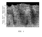
Fig. 1 is a photomicrograph showing a 1 mil spallation-resistant layer above a 1 mil oxidation resistant layer; and -
Fig. 2 is a schematic representation of a coating system in accordance with the instant disclosure; and -
Fig. 3 is a schematic representation of an alternative coating system in accordance with the instant disclosure. - Referring now to
Fig. 2 , the present disclosure relates to a coating system for a turbine engine component such as a turbine vane or blade. The turbine engine component has asubstrate 10 which may be formed from a superalloy material such as a nickel-based superalloy. - Applied to a
surface 12 of the substrate is abond coat 14. Unlike typical bond coats formed from a single layer of a MCrAlY material, thebond coat 14 is a multi-layer coating having an oxidationresistant layer 16 and a spallationresistant layer 18. - The oxidation
resistant layer 16 may comprise a MCrAlY composition such as one having a composition consisting of 20 to 24 wt% cobalt, 14 to 18 wt% chromium, 11 to 13.5 wt% aluminum, 0.1 to 0.4 wt% hafnium, 0.4 to 0.8 wt% yttrium, 0.4 to 0.7 wt% silicon, balance nickel. Thelayer 16 may have a thickness in the range of about 0.5 mil (0.0127 mm) to 7 mil (0.1778 mm). - In accordance with the instant disclosure, the surface of the oxidation
resistant layer 16 is modified with about 0.25 mil (0.00635 mm) to 7.0 mil (0.1778 mm) of a spallation resistant overlay coating orlayer 18 of a different composition. The spallationresistant layer 18 has a composition tailored to form an adherent thermally grown oxide layer (TGO). The spallationresistant layer 18 may have a composition consisting of from 10 to 13 wt% cobalt, from 5.5 to 7.0 wt% chromium, 3.0 to 6.0 wt% tantalum, 3.0 to 5.0 wt% tungsten, 1.1 to 1.7 wt% molybdenum, 9.0 to 11 wt% aluminum, 0.2 to 0.6 wt% hafnium, 0.3 to 0.7 wt% yttrium, from 0.1 to 0.3 wt% silicon, from 0.1 to 0.2 wt% zirconium, and the balance nickel. Alternatively, the spallationresistant layer 18 may have a composition consisting of from 11 to 14 wt% cobalt, from 11 to 14 wt% chromium, from 7.5 to 9.5 wt% aluminum, from 0.1 to 0.5 wt% hafnium, from 0.2 to 0.6 wt% yttrium, from 0.1 to 0.3 wt% silicon, from 0.1 to 0.2 wt% zirconium, and the balance nickel. - The oxidation
resistant layer 16 and the spallationresistant layer 18 may each be deposited using a cathodic arc deposition technique which can be single insertion processing or dual-insertion metallic coating processing. Following deposition, thesubstrate 10 with thelayers - The diffused
bond layer coating 14 formed from thelayers spallation layer 18 mentioned above is used, has an average composition of the two layers which consists of from 10 to 24 wt% cobalt, from 5.5 to 18 wt% chromium, up to 6 wt% tantalum, up to 5.0 wt% tungsten, up to 1.7 wt% molybdenum, from 9 to 13.5 wt% aluminum, 0.1 to 0.6 wt% hafnium, 0.3 to 0.8 wt% yttrium, 0.1 to 0.7 wt% silicon, up to 0.2 wt% zirconium, and the balance nickel. When the second composition for the spallation layer mentioned above is used, the diffusedbond layer coating 14 has a composition consisting of from 11 to 24 wt% cobalt, from 11 to 18 wt% chromium, up to 6 wt% tantalum, up to 5.0 wt% tungsten, up to 1.7 wt% molybdenum, from 7.5 to 13.5 wt% aluminum, 0.1 to 0.5 wt% hafnium, 0.2 to 0.8 wt% yttrium, 0.1 to 0.7 wt% silicon, up to 0.2 wt% zirconium, and the balance nickel. - Following the diffusion heat treatment, the
thermal barrier coating 20 is applied over the multi-layer bond coat. To prepare the metallic coating for thermal barrier coating application, the surface of the metallic coating is mechanically densified. Further the surface modification may be necessary in order to smooth and clean the surface in preparation for TBC deposition. - The
thermal barrier coating 20 may have a duplex/multi-layer thermal barrier coating architecture. Thermal barrier coatings which may be applied include single or multiple layers of yittria-stabilized and/or cubic lanthanide oxide-doped zirconia (or layers of both)deposited via electron-beam physical vapor deposition or air plasma spray methods. The lanthanide oxides have the formula Ln2O3, where Ln=La, Ce, Pr, Nd, Pm, Sm, Eu, Gd, Tb, Dy, Ho, Er, Tm, Yb, and Lu. Alternatively, Y2O3, SC2O3, In2O3, CaO, MgO could be used to dope the cubic zirconia, along with mixtures thereof, and mixtures with any of the lanthanide oxides. - In use, should the thermal barrier coating suffer spallation, the oxidation
resistant coating 14 is formed by thelayers - A coating in accordance with the present disclosure was formed as shown in
FIG. 1 . The coating was formed by preparing a substrate surface via grit blasting and ultrasonic cleaning followed by alcohol cleaning. The substrate was placed into a cathodic arc chamber along with an ingot of an oxidation resistant coating composition as described hereinabove where the oxidation resistant coating composition was deposited. The coating process was then interrupted wherein an oxidation resistant ingot was replaced with a spallation resistant composition as described hereinabove. The coated substrates were then removed from the coating chamber and diffusion heat treated as described hereinabove. - While the
bond layer coating 14 has been described as a two layer metallic coating, as shown inFig. 3 , it could also be a tri-layer metallic coating 14' having a topmost layer 18' with a composition which forms a spallation resistant thermally grown oxide (TGO), a layer 16' which provides the oxidation resistance, and an interfacial layer 17' which is located between the layer 16' and thesubstrate 10. The layer 17' acts to prevent/reduce the formation of secondary reaction zones (SRZ) between the metallic coatings and the substrate. The layer 18' may have a composition such as that set forth forlayer 18 hereinabove. Layer 16' may have a composition such as that set forth forlayer 16 hereinabove. The layer 17' may have a composition similar to the spallation layer but having a low aluminum content. This interfacial layer 17' may have a composition consisting of from 11 to 14 wt% cobalt, from 11 to 14 wt% chromium, from 7.5 to 9.5 wt% aluminum, from 0.1 to 0.5 wt% hafnium, from 0.2 to 0.6 wt% yttrium, from 0.1 to 0.3 wt% silicon, from 0.1 to 0.2 wt% zirconium, and the balance nickel. Alternatively, another suitable composition for the diffusion barrier layer 17' is from 4.5 to 5.5 wt% cobalt, from 9.5 to 10.5 wt% chromium, from 4.0 to 5.5 wt% aluminum, up to 2.0 wt% titanium, about 12 wt% tantalum, and the balance nickel. - Preliminary burner rig oxidation testing of the dual-layer cat arc coating has shown very promising spallation and oxidation resistance compared to single layer/single compositions coatings. Thermal cycles at maximum temperatures ranging from about 2050°F (1121°C) to about 2150°F (1177°C) were conducted in a burner rig test facility to evaluate the spallation and oxidation resistance of these bi-layer metallic coating systems. The TBC spallation resistance improvement using the coating system described herein ranged from 200% to 800% improvement over a conventional bill-of-material bond coat. The oxidation resistance improvement using the coating system described herein ranged from about 15% to 44% improvement over the conventional bill-of-material (oxidation resistant) bond coat.
- The increased oxidation and spallation resistance provided by the coatings disclosed herein can provide improved part life (longer time on-wing) and/or improved thermal efficiency for the engine (reducing TSFC).
- The various layers of the coating systems disclosed herein may be fabricated by a process using a single-insertion processing method by which all layers may be formed in succession without breaking vacuum. Single-insertion processing is useful because it reduces the processing costs associated with the production of a multi-layer metallic coating via conventional methods. Alternatively, the various layers of the coating systems disclosed herein may be fabricated by a multiple insertion process such as a dual insertion method. Still further, fabrication processes include LPPS, EB-PVD, sputtering, and cathodic arc deposition.
- There has been disclosed herein a multi-layer metallic coating for thermal barrier coating systems. While the coating has been described in the context of specific embodiments thereof, other unforeseen alternatives, modifications, and variations may be apparent to those skilled in the art having read the foregoing disclosure. Accordingly, it is intended to embrace those alternatives, modifications, and variations, as fall within the broad scope of the appended claims.
Claims (15)
- A coating system for a turbine engine component having a substrate (12), said coating system comprising:a multi-layer bond coat (14;14') applied to said substrate (12); andsaid multi-layer bond coat (14;14') having an oxidation resistant layer (16;16') and a spallation resistant layer (18;18') deposited over said oxidation resistant layer (16;16').
- A process for forming a coating system on a turbine engine component comprising the steps of:providing a substrate (12);depositing a multi-layer bond coating (14;14') on said substrate,wherein said depositing step comprises depositing an oxidation resistant layer (16;16') and thereafter depositing a spallation resistant layer (18;18') over said oxidation resistant layer (16;16').
- The coating system or process of claim 1 or 2, further comprising a thermal barrier coating (20) deposited over said multi-layer bond coat (14;14') or forming a thermal barrier coating (20) over said multi-layer bond coat (14;14').
- The coating system or process of any preceding claim, wherein said oxidation resistant layer (16;16') has a composition consisting of 20 to 24 wt% cobalt, 14 to 18 wt% chromium, 11 to 13.5 wt% aluminum, 0.1 to 0.4 wt% hafnium, 0.4 to 0.8 wt% yttrium, 0.4 to 0.7 wt% silicon, balance nickel.
- The coating system or process of any of claims 1 to 3, wherein said spallation resistant layer has a composition consisting of from 10 to 13 wt% cobalt, from 5.5 to 7.0 wt% chromium, 3.0 to 6.0 wt% tantalum, 3.0 to 5.0 wt% tungsten, 1.1 to 1.7 wt% molybdenum, 9.0 to 11 wt% aluminum, 0.2 to 0.6 wt% hafnium, 0.3 to 0.7 wt% yttrium, from 0.1 to 0.3 wt% silicon, from 0.1 to 0.2 wt% zirconium, and the balance nickel.
- The coating system or process of any of claims 1 to 3, wherein said spallation resistant layer (18;18') has a composition consisting of from 11 to 14 wt% cobalt, from 11 to 14 wt% chromium, from 7.5 to 9.5 wt% aluminum, from 0.1 to 0.5 wt% hafnium, from 0.2 to 0.6 wt% yttrium, from 0.1 to 0.3 wt% silicon, from 0.1 to 0.2 wt% zirconium, and the balance nickel.
- The process of any of claims 2 to 6, further comprising subjecting said multi-layer bond coat (14;14') to a diffusion heat treatment.
- The process of claim 7, further comprising mechanically densifying and preparing a surface of the bond coat (14;14') following said diffusion heat treatment.
- The process of claim 7 or 8, wherein said diffusion heat treatment step forms a multi-layer bond coat (14;14') having an average composition for both layers consisting of from 10 to 24 wt% cobalt, from 5.5 to 18 wt% chromium, up to 6 wt% tantalum, up to 5.0 wt% tungsten, up to 1.7 wt% molybdenum, from 9 to 13.5 wt% aluminum, 0.1 to 0.6 wt% hafnium, 0.3 to 0.8 wt% yttrium, 0.1 to 0.7 wt% silicon, up to 0.2 wt% zirconium, and the balance nickel; or the coating system of any of claims 1 or 3 to 6 wherein said multi-layer bond coat has an average composition for both layers consisting of from 10 to 24 wt% cobalt, from 5.5 to 18 wt% chromium, up to 6 wt% tantalum, up to 5.0 wt% tungsten, up to 1.7 wt% molybdenum, from 9 to 13.5 wt% aluminum, 0.1 to 0.6 wt% hafnium, 0.3 to 0.8 wt% yttrium, 0.1 to 0.7 wt% silicon, up to 0.2 wt% zirconium, and the balance nickel.
- The process of claim 7 or 8, wherein said diffusion heat treatment step forms a multi-layer bond coat (14;14') having an average composition for both layers consisting of from 11 to 24 wt% cobalt, from 11 to 18 wt% chromium, up to 6 wt% tantalum, up to 5.0 wt% tungsten, up to 1.7 wt% molybdenum, from 7.5 to 13.5 wt% aluminum, 0.1 to 0.5 wt% hafnium, 0.2 to 0.8 wt% yttrium, 0.1 to 0.7 wt% silicon, up to 0.2 wt% zirconium, and the balance nickel; or the coating system of any of claims 1 or 3 to 6 wherein said multi-layer bond coat (14;14') has an average composition for both layers (16,18;16',18') consisting of from 11 to 24 wt% cobalt, from 11 to 18 wt% chromium, up to 6 wt% tantalum, up to 5.0 wt% tungsten, up to 1.7 wt% molybdenum, from 7.5 to 13.5 wt% aluminum, 0.1 to 0.5 wt% hafnium, 0.2 to 0.8 wt% yttrium, 0.1 to 0.7 wt% silicon, up to 0.2 wt% zirconium, and the balance nickel.
- The coating system or process of any preceding claim, further comprising said multi-layer bond coat having an interfacial layer (17') between said oxidation resistant layer (16') and said substrate (12) or forming said multi-layer bond coat (14') with a interfacial layer (17') between said oxidation resistant layer (16') and said substrate (12).
- The coating system or process of claim 11, wherein said interfacial layer (17') has a composition consisting of from 11 to 14 wt% cobalt, from 11 to 14 wt% chromium, from 7.5 to 9.5 wt% aluminum, from 0.1 to 0.5 wt% hafnium, from 0.2 to 0.6 wt% yttrium, from 0.1 to 0.3 wt% silicon, from 0.1 to 0.2 wt% zirconium, and the balance nickel.
- The coating system or process of claim 11, wherein said interfacial layer (17') has a composition consisting of 4.5 to 5.5 wt% cobalt, from 9.5 to 10.5 wt% chromium, from 4.0 to 5.5 wt% aluminum, up to 2.0 wt% titanium, about 12 wt% tantalum, and the balance nickel.
- The process of any of claims 2 to 13, wherein said depositing steps comprise utilizing a single-insertion process method by which all said layers are formed in succession without breaking vacuum, said method comprising, for example, a cathodic arc deposition method.
- The process of any of claims 2 to 13, wherein said depositing step comprises utilizing a multiple insertion process method.
Applications Claiming Priority (1)
| Application Number | Priority Date | Filing Date | Title |
|---|---|---|---|
| US12/987,319 US8497028B1 (en) | 2011-01-10 | 2011-01-10 | Multi-layer metallic coating for TBC systems |
Publications (2)
| Publication Number | Publication Date |
|---|---|
| EP2474648A2 true EP2474648A2 (en) | 2012-07-11 |
| EP2474648A3 EP2474648A3 (en) | 2012-10-31 |
Family
ID=45023624
Family Applications (1)
| Application Number | Title | Priority Date | Filing Date |
|---|---|---|---|
| EP11188118A Withdrawn EP2474648A3 (en) | 2011-01-10 | 2011-11-07 | Multi-layer metallic coating for TBC systems |
Country Status (2)
| Country | Link |
|---|---|
| US (1) | US8497028B1 (en) |
| EP (1) | EP2474648A3 (en) |
Cited By (2)
| Publication number | Priority date | Publication date | Assignee | Title |
|---|---|---|---|---|
| CN104593640A (en) * | 2015-01-30 | 2015-05-06 | 清华大学 | Bonding layer material containing various active elements and used for thermal barrier coating |
| EP4289613A1 (en) * | 2022-06-12 | 2023-12-13 | Pratt & Whitney Canada Corp. | Oxidation and srz resistant coatings on nickel superalloys |
Families Citing this family (5)
| Publication number | Priority date | Publication date | Assignee | Title |
|---|---|---|---|---|
| US20160214350A1 (en) | 2012-08-20 | 2016-07-28 | Pratt & Whitney Canada Corp. | Oxidation-Resistant Coated Superalloy |
| US11261742B2 (en) | 2013-11-19 | 2022-03-01 | Raytheon Technologies Corporation | Article having variable composition coating |
| US10859267B2 (en) | 2013-12-18 | 2020-12-08 | Raytheon Technologies Corporation | Oxidation resistant thermal barrier coating system for combustor panels |
| DE102016002630A1 (en) | 2016-03-07 | 2017-09-07 | Forschungszentrum Jülich GmbH | Adhesive layer for bonding a high-temperature protective layer on a substrate, and method for producing the same |
| CN114058999A (en) * | 2021-11-19 | 2022-02-18 | 西安热工研究院有限公司 | Thermal barrier coating for inhibiting mutual diffusion of elements of base body/thermal barrier coating bonding layer |
Citations (2)
| Publication number | Priority date | Publication date | Assignee | Title |
|---|---|---|---|---|
| EP1801263A1 (en) * | 2005-12-21 | 2007-06-27 | United Technologies Corporation | Platinum modified NiCoCrAly bondcoat for thermal barrier coating |
| EP1837412A2 (en) * | 2006-03-24 | 2007-09-26 | United Technologies Corporation | Coating suitable for use as a bondcoat in a thermal barrier coating system |
Family Cites Families (4)
| Publication number | Priority date | Publication date | Assignee | Title |
|---|---|---|---|---|
| US7316850B2 (en) * | 2004-03-02 | 2008-01-08 | Honeywell International Inc. | Modified MCrAlY coatings on turbine blade tips with improved durability |
| US20090075115A1 (en) | 2007-04-30 | 2009-03-19 | Tryon Brian S | Multi-layered thermal barrier coating |
| US8968528B2 (en) | 2008-04-14 | 2015-03-03 | United Technologies Corporation | Platinum-modified cathodic arc coating |
| US20110256421A1 (en) * | 2010-04-16 | 2011-10-20 | United Technologies Corporation | Metallic coating for single crystal alloys |
-
2011
- 2011-01-10 US US12/987,319 patent/US8497028B1/en active Active
- 2011-11-07 EP EP11188118A patent/EP2474648A3/en not_active Withdrawn
Patent Citations (2)
| Publication number | Priority date | Publication date | Assignee | Title |
|---|---|---|---|---|
| EP1801263A1 (en) * | 2005-12-21 | 2007-06-27 | United Technologies Corporation | Platinum modified NiCoCrAly bondcoat for thermal barrier coating |
| EP1837412A2 (en) * | 2006-03-24 | 2007-09-26 | United Technologies Corporation | Coating suitable for use as a bondcoat in a thermal barrier coating system |
Cited By (2)
| Publication number | Priority date | Publication date | Assignee | Title |
|---|---|---|---|---|
| CN104593640A (en) * | 2015-01-30 | 2015-05-06 | 清华大学 | Bonding layer material containing various active elements and used for thermal barrier coating |
| EP4289613A1 (en) * | 2022-06-12 | 2023-12-13 | Pratt & Whitney Canada Corp. | Oxidation and srz resistant coatings on nickel superalloys |
Also Published As
| Publication number | Publication date |
|---|---|
| EP2474648A3 (en) | 2012-10-31 |
| US8497028B1 (en) | 2013-07-30 |
Similar Documents
| Publication | Publication Date | Title |
|---|---|---|
| US7972657B2 (en) | Silicate resistant thermal barrier coating with alternating layers | |
| US8080283B2 (en) | Method for forming a yttria-stabilized zirconia coating with a molten silicate resistant outer layer | |
| US8497028B1 (en) | Multi-layer metallic coating for TBC systems | |
| US7785722B2 (en) | CMAS resistant thermal barrier coating | |
| KR100687123B1 (en) | Thin 7WS interfacial layer as a periodic endurance (break) lifespan for low conductivity TVs | |
| EP1820879B1 (en) | Durable reactive thermal barrier coatings | |
| EP1889949B1 (en) | Sodium containing thermal barrier coating | |
| US20030157363A1 (en) | Plasma sprayed thermal bond coat system | |
| US20240011402A1 (en) | Reactive thermal barrier coating | |
| EP1908857A2 (en) | Method for forming a thermal barrier coating | |
| CN112756232A (en) | Repair coating system and method | |
| EP2281924A1 (en) | Structually diverse thermal barrier coatings | |
| EP2945798B1 (en) | Thermal barrier coating for cmas resistance and low thermal conductivity | |
| EP1526111B1 (en) | Nano-multilayered structures, components and associated methods of manufacture | |
| EP0985745B1 (en) | Bond coat for a thermal barrier coating system | |
| US10260141B2 (en) | Method of forming a thermal barrier coating with improved adhesion | |
| EP2830876B1 (en) | Multi-material thermal barrier coating system | |
| CN113073285B (en) | Thermal barrier coating and preparation method and application thereof | |
| EP2339051B1 (en) | Article having thermal barrier coating | |
| WO2002027066A2 (en) | Thermal barrier coating resistant to sintering | |
| EP2309024A2 (en) | Process of forming a coating system, coating system formed thereby, and components coated therewith | |
| US20190203333A1 (en) | Thermal barrier coating with improved adhesion |
Legal Events
| Date | Code | Title | Description |
|---|---|---|---|
| PUAI | Public reference made under article 153(3) epc to a published international application that has entered the european phase |
Free format text: ORIGINAL CODE: 0009012 |
|
| AK | Designated contracting states |
Kind code of ref document: A2 Designated state(s): AL AT BE BG CH CY CZ DE DK EE ES FI FR GB GR HR HU IE IS IT LI LT LU LV MC MK MT NL NO PL PT RO RS SE SI SK SM TR |
|
| AX | Request for extension of the european patent |
Extension state: BA ME |
|
| PUAL | Search report despatched |
Free format text: ORIGINAL CODE: 0009013 |
|
| AK | Designated contracting states |
Kind code of ref document: A3 Designated state(s): AL AT BE BG CH CY CZ DE DK EE ES FI FR GB GR HR HU IE IS IT LI LT LU LV MC MK MT NL NO PL PT RO RS SE SI SK SM TR |
|
| AX | Request for extension of the european patent |
Extension state: BA ME |
|
| RIC1 | Information provided on ipc code assigned before grant |
Ipc: C23C 28/02 20060101ALI20120926BHEP Ipc: C23C 28/00 20060101AFI20120926BHEP Ipc: C22C 19/05 20060101ALI20120926BHEP |
|
| 17P | Request for examination filed |
Effective date: 20130429 |
|
| GRAP | Despatch of communication of intention to grant a patent |
Free format text: ORIGINAL CODE: EPIDOSNIGR1 |
|
| INTG | Intention to grant announced |
Effective date: 20130802 |
|
| STAA | Information on the status of an ep patent application or granted ep patent |
Free format text: STATUS: THE APPLICATION IS DEEMED TO BE WITHDRAWN |
|
| 18D | Application deemed to be withdrawn |
Effective date: 20131213 |