EP2474501A1 - Energy production device and associated processes - Google Patents
Energy production device and associated processes Download PDFInfo
- Publication number
- EP2474501A1 EP2474501A1 EP12075001A EP12075001A EP2474501A1 EP 2474501 A1 EP2474501 A1 EP 2474501A1 EP 12075001 A EP12075001 A EP 12075001A EP 12075001 A EP12075001 A EP 12075001A EP 2474501 A1 EP2474501 A1 EP 2474501A1
- Authority
- EP
- European Patent Office
- Prior art keywords
- chemical compound
- hydrogen
- reservoir
- work function
- low electron
- Prior art date
- Legal status (The legal status is an assumption and is not a legal conclusion. Google has not performed a legal analysis and makes no representation as to the accuracy of the status listed.)
- Ceased
Links
- 238000004519 manufacturing process Methods 0.000 title claims description 24
- 238000000034 method Methods 0.000 title claims description 15
- 230000008569 process Effects 0.000 title claims description 11
- 150000001875 compounds Chemical class 0.000 claims abstract description 64
- 239000001257 hydrogen Substances 0.000 claims abstract description 64
- 229910052739 hydrogen Inorganic materials 0.000 claims abstract description 64
- UFHFLCQGNIYNRP-UHFFFAOYSA-N Hydrogen Chemical compound [H][H] UFHFLCQGNIYNRP-UHFFFAOYSA-N 0.000 claims abstract description 59
- 239000007789 gas Substances 0.000 claims abstract description 13
- PXHVJJICTQNCMI-UHFFFAOYSA-N Nickel Chemical compound [Ni] PXHVJJICTQNCMI-UHFFFAOYSA-N 0.000 claims description 22
- 229910052751 metal Inorganic materials 0.000 claims description 20
- 239000002184 metal Substances 0.000 claims description 20
- 238000011068 loading method Methods 0.000 claims description 19
- 150000004678 hydrides Chemical class 0.000 claims description 10
- 239000002243 precursor Substances 0.000 claims description 10
- RTAQQCXQSZGOHL-UHFFFAOYSA-N Titanium Chemical compound [Ti] RTAQQCXQSZGOHL-UHFFFAOYSA-N 0.000 claims description 8
- 229910052759 nickel Inorganic materials 0.000 claims description 8
- 125000004429 atom Chemical group 0.000 claims description 7
- 239000010936 titanium Substances 0.000 claims description 7
- XEEYBQQBJWHFJM-UHFFFAOYSA-N Iron Chemical compound [Fe] XEEYBQQBJWHFJM-UHFFFAOYSA-N 0.000 claims description 6
- BRPQOXSCLDDYGP-UHFFFAOYSA-N calcium oxide Chemical compound [O-2].[Ca+2] BRPQOXSCLDDYGP-UHFFFAOYSA-N 0.000 claims description 6
- ODINCKMPIJJUCX-UHFFFAOYSA-N calcium oxide Inorganic materials [Ca]=O ODINCKMPIJJUCX-UHFFFAOYSA-N 0.000 claims description 6
- 239000000292 calcium oxide Substances 0.000 claims description 6
- 239000000203 mixture Substances 0.000 claims description 6
- 229910052719 titanium Inorganic materials 0.000 claims description 6
- RYGMFSIKBFXOCR-UHFFFAOYSA-N Copper Chemical compound [Cu] RYGMFSIKBFXOCR-UHFFFAOYSA-N 0.000 claims description 5
- 229910045601 alloy Inorganic materials 0.000 claims description 5
- 239000000956 alloy Substances 0.000 claims description 5
- 229910052802 copper Inorganic materials 0.000 claims description 5
- 239000010949 copper Substances 0.000 claims description 5
- 238000010438 heat treatment Methods 0.000 claims description 5
- 150000002431 hydrogen Chemical class 0.000 claims description 5
- KDLHZDBZIXYQEI-UHFFFAOYSA-N Palladium Chemical compound [Pd] KDLHZDBZIXYQEI-UHFFFAOYSA-N 0.000 claims description 4
- 238000001033 granulometry Methods 0.000 claims description 4
- 229910052746 lanthanum Inorganic materials 0.000 claims description 4
- FZLIPJUXYLNCLC-UHFFFAOYSA-N lanthanum atom Chemical compound [La] FZLIPJUXYLNCLC-UHFFFAOYSA-N 0.000 claims description 4
- -1 Ceasium Chemical compound 0.000 claims description 3
- 229910052742 iron Inorganic materials 0.000 claims description 3
- ZSLUVFAKFWKJRC-IGMARMGPSA-N 232Th Chemical compound [232Th] ZSLUVFAKFWKJRC-IGMARMGPSA-N 0.000 claims description 2
- 229910052695 Americium Inorganic materials 0.000 claims description 2
- OYPRJOBELJOOCE-UHFFFAOYSA-N Calcium Chemical compound [Ca] OYPRJOBELJOOCE-UHFFFAOYSA-N 0.000 claims description 2
- VYZAMTAEIAYCRO-UHFFFAOYSA-N Chromium Chemical compound [Cr] VYZAMTAEIAYCRO-UHFFFAOYSA-N 0.000 claims description 2
- 229910052692 Dysprosium Inorganic materials 0.000 claims description 2
- 229910052691 Erbium Inorganic materials 0.000 claims description 2
- 229910052693 Europium Inorganic materials 0.000 claims description 2
- 229910052688 Gadolinium Inorganic materials 0.000 claims description 2
- 229910052689 Holmium Inorganic materials 0.000 claims description 2
- FYYHWMGAXLPEAU-UHFFFAOYSA-N Magnesium Chemical compound [Mg] FYYHWMGAXLPEAU-UHFFFAOYSA-N 0.000 claims description 2
- 229910052779 Neodymium Inorganic materials 0.000 claims description 2
- 229910052781 Neptunium Inorganic materials 0.000 claims description 2
- 229910052778 Plutonium Inorganic materials 0.000 claims description 2
- 229910052777 Praseodymium Inorganic materials 0.000 claims description 2
- 229910052772 Samarium Inorganic materials 0.000 claims description 2
- 229910052771 Terbium Inorganic materials 0.000 claims description 2
- 229910052776 Thorium Inorganic materials 0.000 claims description 2
- 229910052775 Thulium Inorganic materials 0.000 claims description 2
- 229910052770 Uranium Inorganic materials 0.000 claims description 2
- QCWXUUIWCKQGHC-UHFFFAOYSA-N Zirconium Chemical compound [Zr] QCWXUUIWCKQGHC-UHFFFAOYSA-N 0.000 claims description 2
- 229910052768 actinide Inorganic materials 0.000 claims description 2
- 150000001255 actinides Chemical class 0.000 claims description 2
- 229910052767 actinium Inorganic materials 0.000 claims description 2
- QQINRWTZWGJFDB-UHFFFAOYSA-N actinium atom Chemical compound [Ac] QQINRWTZWGJFDB-UHFFFAOYSA-N 0.000 claims description 2
- LXQXZNRPTYVCNG-UHFFFAOYSA-N americium atom Chemical compound [Am] LXQXZNRPTYVCNG-UHFFFAOYSA-N 0.000 claims description 2
- 229910052791 calcium Inorganic materials 0.000 claims description 2
- 239000011575 calcium Substances 0.000 claims description 2
- 229910052804 chromium Inorganic materials 0.000 claims description 2
- 239000011651 chromium Substances 0.000 claims description 2
- 229910017052 cobalt Inorganic materials 0.000 claims description 2
- 239000010941 cobalt Substances 0.000 claims description 2
- GUTLYIVDDKVIGB-UHFFFAOYSA-N cobalt atom Chemical compound [Co] GUTLYIVDDKVIGB-UHFFFAOYSA-N 0.000 claims description 2
- KBQHZAAAGSGFKK-UHFFFAOYSA-N dysprosium atom Chemical compound [Dy] KBQHZAAAGSGFKK-UHFFFAOYSA-N 0.000 claims description 2
- UYAHIZSMUZPPFV-UHFFFAOYSA-N erbium Chemical compound [Er] UYAHIZSMUZPPFV-UHFFFAOYSA-N 0.000 claims description 2
- OGPBJKLSAFTDLK-UHFFFAOYSA-N europium atom Chemical compound [Eu] OGPBJKLSAFTDLK-UHFFFAOYSA-N 0.000 claims description 2
- UIWYJDYFSGRHKR-UHFFFAOYSA-N gadolinium atom Chemical compound [Gd] UIWYJDYFSGRHKR-UHFFFAOYSA-N 0.000 claims description 2
- 229910052735 hafnium Inorganic materials 0.000 claims description 2
- VBJZVLUMGGDVMO-UHFFFAOYSA-N hafnium atom Chemical compound [Hf] VBJZVLUMGGDVMO-UHFFFAOYSA-N 0.000 claims description 2
- KJZYNXUDTRRSPN-UHFFFAOYSA-N holmium atom Chemical compound [Ho] KJZYNXUDTRRSPN-UHFFFAOYSA-N 0.000 claims description 2
- 229910052747 lanthanoid Inorganic materials 0.000 claims description 2
- 150000002602 lanthanoids Chemical class 0.000 claims description 2
- OHSVLFRHMCKCQY-UHFFFAOYSA-N lutetium atom Chemical compound [Lu] OHSVLFRHMCKCQY-UHFFFAOYSA-N 0.000 claims description 2
- 229910052749 magnesium Inorganic materials 0.000 claims description 2
- 239000011777 magnesium Substances 0.000 claims description 2
- QEFYFXOXNSNQGX-UHFFFAOYSA-N neodymium atom Chemical compound [Nd] QEFYFXOXNSNQGX-UHFFFAOYSA-N 0.000 claims description 2
- LFNLGNPSGWYGGD-UHFFFAOYSA-N neptunium atom Chemical compound [Np] LFNLGNPSGWYGGD-UHFFFAOYSA-N 0.000 claims description 2
- 229910052758 niobium Inorganic materials 0.000 claims description 2
- 239000010955 niobium Substances 0.000 claims description 2
- GUCVJGMIXFAOAE-UHFFFAOYSA-N niobium atom Chemical compound [Nb] GUCVJGMIXFAOAE-UHFFFAOYSA-N 0.000 claims description 2
- 229910052763 palladium Inorganic materials 0.000 claims description 2
- OYEHPCDNVJXUIW-UHFFFAOYSA-N plutonium atom Chemical compound [Pu] OYEHPCDNVJXUIW-UHFFFAOYSA-N 0.000 claims description 2
- PUDIUYLPXJFUGB-UHFFFAOYSA-N praseodymium atom Chemical compound [Pr] PUDIUYLPXJFUGB-UHFFFAOYSA-N 0.000 claims description 2
- KZUNJOHGWZRPMI-UHFFFAOYSA-N samarium atom Chemical compound [Sm] KZUNJOHGWZRPMI-UHFFFAOYSA-N 0.000 claims description 2
- 229910052706 scandium Inorganic materials 0.000 claims description 2
- SIXSYDAISGFNSX-UHFFFAOYSA-N scandium atom Chemical compound [Sc] SIXSYDAISGFNSX-UHFFFAOYSA-N 0.000 claims description 2
- 229910052715 tantalum Inorganic materials 0.000 claims description 2
- GUVRBAGPIYLISA-UHFFFAOYSA-N tantalum atom Chemical compound [Ta] GUVRBAGPIYLISA-UHFFFAOYSA-N 0.000 claims description 2
- GZCRRIHWUXGPOV-UHFFFAOYSA-N terbium atom Chemical compound [Tb] GZCRRIHWUXGPOV-UHFFFAOYSA-N 0.000 claims description 2
- 229910052723 transition metal Inorganic materials 0.000 claims description 2
- 150000003624 transition metals Chemical class 0.000 claims description 2
- DNYWZCXLKNTFFI-UHFFFAOYSA-N uranium Chemical compound [U][U][U][U][U][U][U][U][U][U][U][U][U][U][U][U][U][U][U][U][U][U][U][U][U][U][U][U][U][U][U][U][U][U][U][U][U][U][U][U][U][U][U][U][U][U][U][U][U][U][U][U][U][U][U][U][U][U][U][U][U][U][U][U][U][U][U][U][U][U][U][U][U][U][U][U][U][U][U][U][U][U][U][U][U][U][U][U][U][U][U][U][U][U][U][U][U][U][U][U][U][U][U][U][U][U][U][U][U][U][U][U][U][U] DNYWZCXLKNTFFI-UHFFFAOYSA-N 0.000 claims description 2
- 229910052720 vanadium Inorganic materials 0.000 claims description 2
- 229910052727 yttrium Inorganic materials 0.000 claims description 2
- VWQVUPCCIRVNHF-UHFFFAOYSA-N yttrium atom Chemical compound [Y] VWQVUPCCIRVNHF-UHFFFAOYSA-N 0.000 claims description 2
- 229910052726 zirconium Inorganic materials 0.000 claims description 2
- 230000003213 activating effect Effects 0.000 claims 1
- 239000007795 chemical reaction product Substances 0.000 claims 1
- 125000004122 cyclic group Chemical group 0.000 claims 1
- 238000000227 grinding Methods 0.000 claims 1
- 239000008188 pellet Substances 0.000 claims 1
- 238000001556 precipitation Methods 0.000 claims 1
- GPPXJZIENCGNKB-UHFFFAOYSA-N vanadium Chemical compound [V]#[V] GPPXJZIENCGNKB-UHFFFAOYSA-N 0.000 claims 1
- 238000002474 experimental method Methods 0.000 description 14
- 229940126062 Compound A Drugs 0.000 description 13
- NLDMNSXOCDLTTB-UHFFFAOYSA-N Heterophylliin A Natural products O1C2COC(=O)C3=CC(O)=C(O)C(O)=C3C3=C(O)C(O)=C(O)C=C3C(=O)OC2C(OC(=O)C=2C=C(O)C(O)=C(O)C=2)C(O)C1OC(=O)C1=CC(O)=C(O)C(O)=C1 NLDMNSXOCDLTTB-UHFFFAOYSA-N 0.000 description 13
- 239000002775 capsule Substances 0.000 description 12
- 239000000463 material Substances 0.000 description 12
- 238000006243 chemical reaction Methods 0.000 description 11
- 230000015572 biosynthetic process Effects 0.000 description 7
- 150000002739 metals Chemical class 0.000 description 7
- 239000000523 sample Substances 0.000 description 7
- 230000001955 cumulated effect Effects 0.000 description 6
- 239000000126 substance Substances 0.000 description 6
- 125000004435 hydrogen atom Chemical group [H]* 0.000 description 5
- 238000011065 in-situ storage Methods 0.000 description 5
- 230000003993 interaction Effects 0.000 description 5
- 239000007787 solid Substances 0.000 description 5
- XLYOFNOQVPJJNP-UHFFFAOYSA-N water Substances O XLYOFNOQVPJJNP-UHFFFAOYSA-N 0.000 description 5
- 238000011084 recovery Methods 0.000 description 4
- 238000012360 testing method Methods 0.000 description 4
- 238000006555 catalytic reaction Methods 0.000 description 3
- 239000000843 powder Substances 0.000 description 3
- 230000001052 transient effect Effects 0.000 description 3
- 239000007868 Raney catalyst Substances 0.000 description 2
- 229910000564 Raney nickel Inorganic materials 0.000 description 2
- 239000004411 aluminium Substances 0.000 description 2
- 229910052782 aluminium Inorganic materials 0.000 description 2
- XAGFODPZIPBFFR-UHFFFAOYSA-N aluminium Chemical compound [Al] XAGFODPZIPBFFR-UHFFFAOYSA-N 0.000 description 2
- 238000000429 assembly Methods 0.000 description 2
- 230000000712 assembly Effects 0.000 description 2
- 238000000498 ball milling Methods 0.000 description 2
- 230000004888 barrier function Effects 0.000 description 2
- 239000002270 dispersing agent Substances 0.000 description 2
- 230000004907 flux Effects 0.000 description 2
- 239000013529 heat transfer fluid Substances 0.000 description 2
- 239000011810 insulating material Substances 0.000 description 2
- 239000002105 nanoparticle Substances 0.000 description 2
- HZPNKQREYVVATQ-UHFFFAOYSA-L nickel(2+);diformate Chemical compound [Ni+2].[O-]C=O.[O-]C=O HZPNKQREYVVATQ-UHFFFAOYSA-L 0.000 description 2
- 238000002360 preparation method Methods 0.000 description 2
- BDERNNFJNOPAEC-UHFFFAOYSA-N propan-1-ol Chemical compound CCCO BDERNNFJNOPAEC-UHFFFAOYSA-N 0.000 description 2
- 230000005855 radiation Effects 0.000 description 2
- LEONUFNNVUYDNQ-UHFFFAOYSA-N vanadium atom Chemical group [V] LEONUFNNVUYDNQ-UHFFFAOYSA-N 0.000 description 2
- 229910000619 316 stainless steel Inorganic materials 0.000 description 1
- 238000004438 BET method Methods 0.000 description 1
- 229910005438 FeTi Inorganic materials 0.000 description 1
- 229910052765 Lutetium Inorganic materials 0.000 description 1
- 229910052792 caesium Inorganic materials 0.000 description 1
- TVFDJXOCXUVLDH-UHFFFAOYSA-N caesium atom Chemical compound [Cs] TVFDJXOCXUVLDH-UHFFFAOYSA-N 0.000 description 1
- 239000004020 conductor Substances 0.000 description 1
- 238000010276 construction Methods 0.000 description 1
- 239000012809 cooling fluid Substances 0.000 description 1
- 230000008878 coupling Effects 0.000 description 1
- 238000010168 coupling process Methods 0.000 description 1
- 238000005859 coupling reaction Methods 0.000 description 1
- 230000001351 cycling effect Effects 0.000 description 1
- 230000007423 decrease Effects 0.000 description 1
- 230000018044 dehydration Effects 0.000 description 1
- 238000006297 dehydration reaction Methods 0.000 description 1
- 238000006356 dehydrogenation reaction Methods 0.000 description 1
- 238000010494 dissociation reaction Methods 0.000 description 1
- 230000005593 dissociations Effects 0.000 description 1
- 239000012530 fluid Substances 0.000 description 1
- 239000011491 glass wool Substances 0.000 description 1
- 238000009413 insulation Methods 0.000 description 1
- 238000005259 measurement Methods 0.000 description 1
- 230000004048 modification Effects 0.000 description 1
- 238000012986 modification Methods 0.000 description 1
- 238000012544 monitoring process Methods 0.000 description 1
- 229910000480 nickel oxide Inorganic materials 0.000 description 1
- SMAMDWMLHWVJQM-UHFFFAOYSA-L nickel(2+);diformate;dihydrate Chemical compound O.O.[Ni+2].[O-]C=O.[O-]C=O SMAMDWMLHWVJQM-UHFFFAOYSA-L 0.000 description 1
- 239000002245 particle Substances 0.000 description 1
- 230000010399 physical interaction Effects 0.000 description 1
- 238000004064 recycling Methods 0.000 description 1
- 230000001105 regulatory effect Effects 0.000 description 1
- 238000009877 rendering Methods 0.000 description 1
- 230000002441 reversible effect Effects 0.000 description 1
- 238000003860 storage Methods 0.000 description 1
- 230000002459 sustained effect Effects 0.000 description 1
- 229910000048 titanium hydride Inorganic materials 0.000 description 1
- OGIDPMRJRNCKJF-UHFFFAOYSA-N titanium oxide Inorganic materials [Ti]=O OGIDPMRJRNCKJF-UHFFFAOYSA-N 0.000 description 1
- 230000032258 transport Effects 0.000 description 1
Images


Classifications
-
- C—CHEMISTRY; METALLURGY
- C01—INORGANIC CHEMISTRY
- C01B—NON-METALLIC ELEMENTS; COMPOUNDS THEREOF; METALLOIDS OR COMPOUNDS THEREOF NOT COVERED BY SUBCLASS C01C
- C01B3/00—Hydrogen; Gaseous mixtures containing hydrogen; Separation of hydrogen from mixtures containing it; Purification of hydrogen
- C01B3/02—Production of hydrogen or of gaseous mixtures containing a substantial proportion of hydrogen
- C01B3/06—Production of hydrogen or of gaseous mixtures containing a substantial proportion of hydrogen by reaction of inorganic compounds containing electro-positively bound hydrogen, e.g. water, acids, bases, ammonia, with inorganic reducing agents
-
- B—PERFORMING OPERATIONS; TRANSPORTING
- B01—PHYSICAL OR CHEMICAL PROCESSES OR APPARATUS IN GENERAL
- B01D—SEPARATION
- B01D53/00—Separation of gases or vapours; Recovering vapours of volatile solvents from gases; Chemical or biological purification of waste gases, e.g. engine exhaust gases, smoke, fumes, flue gases, aerosols
- B01D53/02—Separation of gases or vapours; Recovering vapours of volatile solvents from gases; Chemical or biological purification of waste gases, e.g. engine exhaust gases, smoke, fumes, flue gases, aerosols by adsorption, e.g. preparative gas chromatography
- B01D53/04—Separation of gases or vapours; Recovering vapours of volatile solvents from gases; Chemical or biological purification of waste gases, e.g. engine exhaust gases, smoke, fumes, flue gases, aerosols by adsorption, e.g. preparative gas chromatography with stationary adsorbents
- B01D53/0407—Constructional details of adsorbing systems
- B01D53/0438—Cooling or heating systems
-
- B—PERFORMING OPERATIONS; TRANSPORTING
- B01—PHYSICAL OR CHEMICAL PROCESSES OR APPARATUS IN GENERAL
- B01J—CHEMICAL OR PHYSICAL PROCESSES, e.g. CATALYSIS OR COLLOID CHEMISTRY; THEIR RELEVANT APPARATUS
- B01J19/00—Chemical, physical or physico-chemical processes in general; Their relevant apparatus
- B01J19/0006—Controlling or regulating processes
- B01J19/0013—Controlling the temperature of the process
-
- B—PERFORMING OPERATIONS; TRANSPORTING
- B01—PHYSICAL OR CHEMICAL PROCESSES OR APPARATUS IN GENERAL
- B01D—SEPARATION
- B01D2253/00—Adsorbents used in seperation treatment of gases and vapours
- B01D2253/10—Inorganic adsorbents
- B01D2253/112—Metals or metal compounds not provided for in B01D2253/104 or B01D2253/106
- B01D2253/1122—Metals
-
- B—PERFORMING OPERATIONS; TRANSPORTING
- B01—PHYSICAL OR CHEMICAL PROCESSES OR APPARATUS IN GENERAL
- B01D—SEPARATION
- B01D2255/00—Catalysts
- B01D2255/10—Noble metals or compounds thereof
- B01D2255/102—Platinum group metals
- B01D2255/1023—Palladium
-
- B—PERFORMING OPERATIONS; TRANSPORTING
- B01—PHYSICAL OR CHEMICAL PROCESSES OR APPARATUS IN GENERAL
- B01D—SEPARATION
- B01D2255/00—Catalysts
- B01D2255/20—Metals or compounds thereof
- B01D2255/204—Alkaline earth metals
- B01D2255/2045—Calcium
-
- B—PERFORMING OPERATIONS; TRANSPORTING
- B01—PHYSICAL OR CHEMICAL PROCESSES OR APPARATUS IN GENERAL
- B01D—SEPARATION
- B01D2255/00—Catalysts
- B01D2255/20—Metals or compounds thereof
- B01D2255/204—Alkaline earth metals
- B01D2255/2047—Magnesium
-
- B—PERFORMING OPERATIONS; TRANSPORTING
- B01—PHYSICAL OR CHEMICAL PROCESSES OR APPARATUS IN GENERAL
- B01D—SEPARATION
- B01D2255/00—Catalysts
- B01D2255/20—Metals or compounds thereof
- B01D2255/206—Rare earth metals
-
- B—PERFORMING OPERATIONS; TRANSPORTING
- B01—PHYSICAL OR CHEMICAL PROCESSES OR APPARATUS IN GENERAL
- B01D—SEPARATION
- B01D2255/00—Catalysts
- B01D2255/20—Metals or compounds thereof
- B01D2255/206—Rare earth metals
- B01D2255/2061—Yttrium
-
- B—PERFORMING OPERATIONS; TRANSPORTING
- B01—PHYSICAL OR CHEMICAL PROCESSES OR APPARATUS IN GENERAL
- B01D—SEPARATION
- B01D2255/00—Catalysts
- B01D2255/20—Metals or compounds thereof
- B01D2255/206—Rare earth metals
- B01D2255/2063—Lanthanum
-
- B—PERFORMING OPERATIONS; TRANSPORTING
- B01—PHYSICAL OR CHEMICAL PROCESSES OR APPARATUS IN GENERAL
- B01D—SEPARATION
- B01D2255/00—Catalysts
- B01D2255/20—Metals or compounds thereof
- B01D2255/206—Rare earth metals
- B01D2255/2066—Praseodymium
-
- B—PERFORMING OPERATIONS; TRANSPORTING
- B01—PHYSICAL OR CHEMICAL PROCESSES OR APPARATUS IN GENERAL
- B01D—SEPARATION
- B01D2255/00—Catalysts
- B01D2255/20—Metals or compounds thereof
- B01D2255/206—Rare earth metals
- B01D2255/2068—Neodymium
-
- B—PERFORMING OPERATIONS; TRANSPORTING
- B01—PHYSICAL OR CHEMICAL PROCESSES OR APPARATUS IN GENERAL
- B01D—SEPARATION
- B01D2255/00—Catalysts
- B01D2255/20—Metals or compounds thereof
- B01D2255/207—Transition metals
- B01D2255/20707—Titanium
-
- B—PERFORMING OPERATIONS; TRANSPORTING
- B01—PHYSICAL OR CHEMICAL PROCESSES OR APPARATUS IN GENERAL
- B01D—SEPARATION
- B01D2255/00—Catalysts
- B01D2255/20—Metals or compounds thereof
- B01D2255/207—Transition metals
- B01D2255/20715—Zirconium
-
- B—PERFORMING OPERATIONS; TRANSPORTING
- B01—PHYSICAL OR CHEMICAL PROCESSES OR APPARATUS IN GENERAL
- B01D—SEPARATION
- B01D2255/00—Catalysts
- B01D2255/20—Metals or compounds thereof
- B01D2255/207—Transition metals
- B01D2255/20723—Vanadium
-
- B—PERFORMING OPERATIONS; TRANSPORTING
- B01—PHYSICAL OR CHEMICAL PROCESSES OR APPARATUS IN GENERAL
- B01D—SEPARATION
- B01D2255/00—Catalysts
- B01D2255/20—Metals or compounds thereof
- B01D2255/207—Transition metals
- B01D2255/20738—Iron
-
- B—PERFORMING OPERATIONS; TRANSPORTING
- B01—PHYSICAL OR CHEMICAL PROCESSES OR APPARATUS IN GENERAL
- B01D—SEPARATION
- B01D2255/00—Catalysts
- B01D2255/20—Metals or compounds thereof
- B01D2255/207—Transition metals
- B01D2255/20746—Cobalt
-
- B—PERFORMING OPERATIONS; TRANSPORTING
- B01—PHYSICAL OR CHEMICAL PROCESSES OR APPARATUS IN GENERAL
- B01D—SEPARATION
- B01D2255/00—Catalysts
- B01D2255/20—Metals or compounds thereof
- B01D2255/207—Transition metals
- B01D2255/20753—Nickel
-
- B—PERFORMING OPERATIONS; TRANSPORTING
- B01—PHYSICAL OR CHEMICAL PROCESSES OR APPARATUS IN GENERAL
- B01D—SEPARATION
- B01D2255/00—Catalysts
- B01D2255/20—Metals or compounds thereof
- B01D2255/207—Transition metals
- B01D2255/20761—Copper
-
- B—PERFORMING OPERATIONS; TRANSPORTING
- B01—PHYSICAL OR CHEMICAL PROCESSES OR APPARATUS IN GENERAL
- B01D—SEPARATION
- B01D2255/00—Catalysts
- B01D2255/20—Metals or compounds thereof
- B01D2255/207—Transition metals
- B01D2255/20784—Chromium
-
- B—PERFORMING OPERATIONS; TRANSPORTING
- B01—PHYSICAL OR CHEMICAL PROCESSES OR APPARATUS IN GENERAL
- B01D—SEPARATION
- B01D2255/00—Catalysts
- B01D2255/20—Metals or compounds thereof
- B01D2255/209—Other metals
-
- B—PERFORMING OPERATIONS; TRANSPORTING
- B01—PHYSICAL OR CHEMICAL PROCESSES OR APPARATUS IN GENERAL
- B01D—SEPARATION
- B01D2256/00—Main component in the product gas stream after treatment
- B01D2256/16—Hydrogen
-
- B—PERFORMING OPERATIONS; TRANSPORTING
- B01—PHYSICAL OR CHEMICAL PROCESSES OR APPARATUS IN GENERAL
- B01D—SEPARATION
- B01D2257/00—Components to be removed
- B01D2257/10—Single element gases other than halogens
- B01D2257/108—Hydrogen
-
- B—PERFORMING OPERATIONS; TRANSPORTING
- B01—PHYSICAL OR CHEMICAL PROCESSES OR APPARATUS IN GENERAL
- B01D—SEPARATION
- B01D2259/00—Type of treatment
- B01D2259/45—Gas separation or purification devices adapted for specific applications
- B01D2259/4525—Gas separation or purification devices adapted for specific applications for storage and dispensing systems
-
- B—PERFORMING OPERATIONS; TRANSPORTING
- B01—PHYSICAL OR CHEMICAL PROCESSES OR APPARATUS IN GENERAL
- B01J—CHEMICAL OR PHYSICAL PROCESSES, e.g. CATALYSIS OR COLLOID CHEMISTRY; THEIR RELEVANT APPARATUS
- B01J2219/00—Chemical, physical or physico-chemical processes in general; Their relevant apparatus
- B01J2219/00049—Controlling or regulating processes
- B01J2219/00051—Controlling the temperature
- B01J2219/00074—Controlling the temperature by indirect heating or cooling employing heat exchange fluids
- B01J2219/00105—Controlling the temperature by indirect heating or cooling employing heat exchange fluids part or all of the reactants being heated or cooled outside the reactor while recycling
- B01J2219/00108—Controlling the temperature by indirect heating or cooling employing heat exchange fluids part or all of the reactants being heated or cooled outside the reactor while recycling involving reactant vapours
-
- B—PERFORMING OPERATIONS; TRANSPORTING
- B01—PHYSICAL OR CHEMICAL PROCESSES OR APPARATUS IN GENERAL
- B01J—CHEMICAL OR PHYSICAL PROCESSES, e.g. CATALYSIS OR COLLOID CHEMISTRY; THEIR RELEVANT APPARATUS
- B01J2219/00—Chemical, physical or physico-chemical processes in general; Their relevant apparatus
- B01J2219/00049—Controlling or regulating processes
- B01J2219/00162—Controlling or regulating processes controlling the pressure
-
- B—PERFORMING OPERATIONS; TRANSPORTING
- B01—PHYSICAL OR CHEMICAL PROCESSES OR APPARATUS IN GENERAL
- B01J—CHEMICAL OR PHYSICAL PROCESSES, e.g. CATALYSIS OR COLLOID CHEMISTRY; THEIR RELEVANT APPARATUS
- B01J2219/00—Chemical, physical or physico-chemical processes in general; Their relevant apparatus
- B01J2219/00049—Controlling or regulating processes
- B01J2219/00164—Controlling or regulating processes controlling the flow
-
- Y—GENERAL TAGGING OF NEW TECHNOLOGICAL DEVELOPMENTS; GENERAL TAGGING OF CROSS-SECTIONAL TECHNOLOGIES SPANNING OVER SEVERAL SECTIONS OF THE IPC; TECHNICAL SUBJECTS COVERED BY FORMER USPC CROSS-REFERENCE ART COLLECTIONS [XRACs] AND DIGESTS
- Y02—TECHNOLOGIES OR APPLICATIONS FOR MITIGATION OR ADAPTATION AGAINST CLIMATE CHANGE
- Y02E—REDUCTION OF GREENHOUSE GAS [GHG] EMISSIONS, RELATED TO ENERGY GENERATION, TRANSMISSION OR DISTRIBUTION
- Y02E30/00—Energy generation of nuclear origin
- Y02E30/10—Nuclear fusion reactors
-
- Y—GENERAL TAGGING OF NEW TECHNOLOGICAL DEVELOPMENTS; GENERAL TAGGING OF CROSS-SECTIONAL TECHNOLOGIES SPANNING OVER SEVERAL SECTIONS OF THE IPC; TECHNICAL SUBJECTS COVERED BY FORMER USPC CROSS-REFERENCE ART COLLECTIONS [XRACs] AND DIGESTS
- Y02—TECHNOLOGIES OR APPLICATIONS FOR MITIGATION OR ADAPTATION AGAINST CLIMATE CHANGE
- Y02E—REDUCTION OF GREENHOUSE GAS [GHG] EMISSIONS, RELATED TO ENERGY GENERATION, TRANSMISSION OR DISTRIBUTION
- Y02E60/00—Enabling technologies; Technologies with a potential or indirect contribution to GHG emissions mitigation
- Y02E60/30—Hydrogen technology
- Y02E60/36—Hydrogen production from non-carbon containing sources, e.g. by water electrolysis
Definitions
- the present invention belongs to the energy production sector.
- the device is composed:
- the invention is, however, not limited to the thermal energy production only.
- One of the main objectives of the present invention is to provide an innovative energy production system, capable of rendering high energy performance trough a system, as defined above, using at least one chemical compound with low electron function characteristic.
- the present invention proposes the energy producing processes as follows:
- Fig. 1 and 3 represent two possible realizations of the system, according to the invention. Independent of the choice of the set-up the following elements need to be present:
- the first mode of the realisation presented in Fig.1 and 2 comprises only one reservoir 10, which is a metallic capsule, of volume 5qc, made from 316-stainless steel, beside the calibration resistance C1placed in a reservoir 10' identical to 10.
- the capsule 10, is placed in the heater 20, capable to heat the content of the capsule 10.
- This system can be defined a differential calorimeter.
- the capsule 10 is placed in the cylindrical support 22, made of an efficient heat conductor, surrounded by insulating layer 21.
- the role of the insulating material 21, which fully fills the shaft between the heater 20 and cylinder 22, is to create a thermal barrier on the heat flux trajectory, generated by the heater 20, towards the aluminium cylinder 22. This thermal barrier creates an important thermal gradient. At the equilibrium temperature of the capsule, which is very close to the temperature of the support 22, measured by the probe 23, the capsule temperature is several degrees lower than the regulated heater temperature, measured by another probe 24.
- the probe 24, is placed between the heater 20 and insulating material 21.
- the probe 23 is placed inside the support 22, between reservoir 10 and resistance C1.
- the support 22 is an Aluminium cylinder
- the shaft 21 is glasswool, but the materials for this purpose may vary.
- Capsule 10 single opening is connected to line 70, permitting the gas containing Hydrogen to circulate.
- the two reservoirs 100 and 200 are foreseen.
- the configuration of these two reservoirs are two concentric metallic tubes, with the same volume capacity. Both reservoirs are connected on both extremities to the line 700, where the gas containing Hydrogen circulates.
- Heating device 300 is preferably placed around the external wall of the cylinder 100.
- Such device can be of any known material and any set-up configuration necessary to heat the content of both reservoirs to the temperature between 300 and 900°C in order to trigger the reaction and it can be turned off after a given amount of time.
- the reservoirs 100 and 200 are placed in an insulated chamber 320.
- Thermal energy produced with this system according to the invention, is then recovered by a heat transfer fluid contained in a pipe 400, that is winded around and heated in the contact with the reservoir 200, and which then conveys the energy to any known user of the thermal energy.
- the means and materials to recover the produced energy can be any means of the state of the art.
- the configuration of energy recovery system 40 ( Fig. 2 ) will be applied to this energy production system according to the invention, in case of power output higher then 100Watt. Below that level of energy production the configuration represented in Fig.1 and 2 is for the study purposes only and for the purpose of the measurements/study accuracy, the thermal energy recovery system is unadvisable.
- the system 40 ( Fig.2 ), will be a metallic tube, placed inside the support 22, from which the heat transfer fluid transports the thermal energy produced according to the invention, into an external heat exchanger and finally to the user.
- the circulation line 70;700 of the gas containing Hydrogen includes the Hydrogen tank 50;500, a vacuum pump 60;600, manifold control valves 71, 72,73,75 ; 610, 620, 630, 640 and the gas expansion turbine 800, in the case of the second possible embodiment.
- flow-meter 76 is placed on this circulation line in order to precisely measure the gas flow entering the capsule 10.
- the capsule 10 and reservoirs 100, 200 contain at least one chemical compound able to ad/absorb Hydrogen.
- Ad-sorbtion is a surface phenomenon, where an Hydrogen atom is bound to an atom of a solid surface. Ab-sobtion instead, is when an Hydrogen atom enters the volume of the solid. It is well known that gases, like di-hydrogen, can ad-sorbe on solids. This phenomenon is the basis of the BET method, to measure the surface of solids. BET was described in 1938, by Brunauer, Emmet and Teller in the "Adsorbtion Of Gases In Multi-Molecular Layers", published in Journal Of American Chemical Society in 1938, Vol. 60, Page 309 .
- bonds involved in the physical ad-sorbtion are weak bonds.
- Van der Waal's bonds weak and electrical interactions between atoms and/or molecules of low intensity with typical values of a few KiloJoules per Mole.
- Hydrogen can also ad-sorb chemically on solids with chemical bonds that can be ionic, co-valent or metallic. Chemical bonds are electromagnetic interactions, with strong energy (between 10 and 300 kJ/mole), implying the electron sharing between atoms.
- Materials of the A group have high Hydrogen ab/adsorbtion capacity and are materials with high electron work function, whereas the materials in the B group, have low hydrogen ab/adsorbtion capacity but have low electron work function.
- the eKa neutron penetrates into the electronic shell of compound A, but because of it's transiency it cannot reach the A compound nucleus. When it reverses to proton and electron these two electrical charges constitute the di-pole, which is attracted by the electrically positive nucleus of the compound A. This di-pole is then bound by electrical attraction to the positive nucleus N A of compound A at very short distance from this nucleus (pico-meters).
- the formation of the eKa neutron is a phenomenon occurring in the transitory state of the system during the Hydrogen loading into the chemical compound able to ab/adsorb Hydrogen under the given pressure increase (previously defined) and only in a well defined pressure variation. In order to create that state in the system, the cycling of the Hydrogen loading and de-loading is recommended.
- the elapsed time of Hydrogen pressurization and de-pressurization cycles depends upon the reservoir volume and the compounds quantity. It also depends upon the way compounds A and B are installed in the reactor.
- a low X-radiation energy screen is advisable.
- the low energy X-photon is emitted with the energy lower or equal to the energy of the pico-hydride formationthat is the energy of the k layer s electrons of A.
- Pico-hydrides are not completely stable and they eventually do transmute with very low reaction rates, hence they do emit nuclear radiations with a very small emission rate. (lower than 10 -10 s -1 )
- Ni(HCO2) 2 ,2H20 Nickel (nano-particles)+CO2+H2+H2O
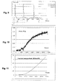
- the support 22 temperature is raised under vacuum to 435°C. Hydrogen is then introduced by steps from 1 to 20 bars in 15 minutes. The energy production then starts and the experiment is stopped when the power is 2.5 W/gNickel ( fig. 11 ) and the cumulated energy 2.3 MJ/moleNickel (Fig. 12), values calculated from the calorimetric equation.
- an inert precursor here Nickel formate
- copper cylinders that can subsequently be safely loaded in the reactor where it is in-situ activated prior to energy generation.
- metals able to absorb hydrogen can store economically valuable amounts of hydrogen.
- the best candidates are metals that have low loading/unloading pressure and temperature. Alloys like NiLa5 and FeTi have extensively been studied.
- the loading/unloading of metals by hydrogen is a reversible reaction, which is exothermal when loading and endothermal when unloading. On a cycle, there is no net energy production.
- What is claimed in this patent is that a mixture of a metal able to absorb hydrogen with a compound having a low electron work function result indeed in a net energy production over a loading/unloading cycle.
- the invention in this patent is to safely prepare a precursor (using Nickel formate for instance). The precursor is then safely loaded in the reactor and activated in situ.
- the invention is not the recipe of the precursor (many such recipes can be found using all the knowledge in the field of catalysis). It is the use of a precursor in the process.
- a nuclear power plant consists basically in a reactor generating heat, coupled to a steam generator, the coupling being through a heat carrier fluid.
- a cylindrical reactor 10 m high and 2 m diameter has an external surface of some 70 m2. If this reactor in insulated by an insulation layer with heat conductivity 0,2 W/mK and thickness 20 cm, the losses are some 30 kW for the whole reactor (reactor temperature 440°C, outside temperature of the insulating layer 50°C).
Landscapes
- Chemical & Material Sciences (AREA)
- Chemical Kinetics & Catalysis (AREA)
- Organic Chemistry (AREA)
- Engineering & Computer Science (AREA)
- Inorganic Chemistry (AREA)
- Combustion & Propulsion (AREA)
- Health & Medical Sciences (AREA)
- General Health & Medical Sciences (AREA)
- Analytical Chemistry (AREA)
- General Chemical & Material Sciences (AREA)
- Oil, Petroleum & Natural Gas (AREA)
- Solid-Sorbent Or Filter-Aiding Compositions (AREA)
- Filling Or Discharging Of Gas Storage Vessels (AREA)
Abstract
- one reservoir (100,200) containing at least a chemical compound able to ad-absorb hydrogen.
- means (300) to heat the content of the reservoir (100,200),
- means (500, 600, 700, 610, 620, 630, 640) to introduce an hydrogen containing gas in said reservoir and means to control the pressure of that gas in the reservoir,
characterized in that the reservoir (100,200) contains also at least a chemical compound having a low work function.
Description
- The present invention belongs to the energy production sector. In detail the device is composed:
- reservoir, containing at least one chemical compound capable of Hydrogen ab/adsorbtion.
- devices that allow the heating of the reservoir
- devices that consent the introduction of gas containing Hydrogen into the reservoir and pressure control device of the same reservoir and
- the created thermal energy recovery device.
- The invention is, however, not limited to the thermal energy production only.
- There are several known and existing attempts of such heat production devices containing Ni and heating resistance where the thermal energy is recovered by cooling fluid, nevertheless none of these reported inventions are supported by rigorous scientific examination facts (data).
- One of the main objectives of the present invention is to provide an innovative energy production system, capable of rendering high energy performance trough a system, as defined above, using at least one chemical compound with low electron function characteristic.
- Such characteristic optimizes the interaction between Hydrogen and chemical compound process increasing the corresponding reaction rate trough the two concurrent processes.
- Further characteristics of the above mentioned system :
- the mentioned chemical compound is a transition metal belonging to the Vanadium group or to the Titanium group or it is an Actinide or Lanthanide adapted to form a metallic hydride or an intermediate hydride between metallic and ionic hydride, or between metallic and covalent hydride.
- the mentioned chemical compound is one selected from the following elements: Scandium, Yttrium, Lanthanum, Actinium, Caesium, Praseodymium, Neodymium, Samarium, Gadolinium, Terbium, Dysprosium, Holmium, Erbium, Thulium, Lutetium, Titanium, Zirconium, Hafnium, Thorium, Protactinium, Uranium, Neptunium, Plutonium, Americium, Vanadium, Niobium, Tantalum, Chromium, Iron, Cobalt, Nickel, Palladium, Magnesium, Europium, Copper.
- the mentioned chemical compound, able to ab/adsorb Hydrogen, can also be an alloy of some or any of the above elements. For example: an alloy Iron/Titanium or an alloy Nickel/Lanthanum.
- the mentioned chemical compound with low electron work function is: an alkaline metal, alkaline earth, oxide of an alkaline metal or oxide of an alkaline earth or a compound comprising at least one atom of alkaline metal or alkaline earth, or further, Calcium or Calcium Oxide.
- the mentioned chemical compound with low electron work function is Lanthanum-hexaboride.
- the mentioned chemical compound capable to ab/adsorb Hydrogen and/or the mentioned chemical compound with low electron work function is formed in-situ, inside the reservoir from another chemical compound.
- the mentioned chemical compound capable to ab/adsorb Hydrogen and/or the mentioned chemical compound with low electron work function is formed in-situ, inside the reservoir by dehydration of another chemical compound or by decarbonation.
- the mentioned chemical compound capable to ab/adsorb Hydrogen and/or the mentioned chemical compound with low electron work function is formed in-situ, inside the reservoir by dehydrogenation of another chemical compound.
- the mentioned chemical compound capable to ab/adsorb Hydrogen and/or the mentioned chemical compound with low electron work function is present inside the reservoir in the form of finely divided particles with granulometry lower or equal to 1mm.
- the volume proportion of the mentioned chemical compound capable to ab/adsorb Hydrogen is lower or equal to 40% of the total volume of both compounds, the other being the mentioned chemical compound with low electron work function.
- two reservoirs, each containing at least one mentioned chemical compound capable to ab/adsorb Hydrogen and at least one mentioned chemical compound with low electron work function, connected and interacting in function of the induced Hydrogen flow.
- The present invention, moreover, proposes the energy producing processes as follows:
- first step in which the mentioned chemical compound capable to ab/adsorb Hydrogen is submitted to the Hydrogen pressure, equal or higher than the 60% of the mean known loading pressure limit, at the temperature of the process. All this, in the presence of at least one chemical compound with low electron work function.
and - second step in which the reacting compounds that underwent the first step are submitted to the Hydrogen pressure, equal or lower than the 40% of the mean known loading pressure limit.
-
-
Fig. 1 , is a first possible realization step schematic view of the system, according to the invention. -
Fig. 2 , is an enlarged cross-sectional view of the reservoir of system of theFig. 1 . -
Fig. 3 , is a second possible schematic view of the system, according to the invention. -Fig. 4 , exhibits the typical known shape of the Langmur's isothermals by which the pressure limits of Hydrogen pressure at given temperature in the two earlier mentioned reservoirs can be determined. -
Fig. 5 , is the literature representation of the loading pressure limit isotherms for metal/hydrogen systems, by which the maximum loading pressure can be determined. -
Fig. 6 , is the determination of the time constant of the calorimeter, where C1 is thetemperature probe 23 of thesupport 22 when the calibration resistance C1 is heated (DC current) during a given time inside thesupport 22, and C2 is the heater temperature. The fit of C1 by an exponential gives the time constant of the calorimeter (s-1) -
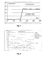
Fig. 7 , is the determination of the water equivalent of the calorimeter, the plot of theFig. 7 expressed in °C, corresponding to the cumulated temperature difference between the reservoir and the heater plus the cumulated temperature differences of thesupport 22 of the system described inFig. 1 . -
Fig. 8 , shows the experimental curves during several cycles, of the energy in Joules produced during the pressurization of the reservoir (curve C6), and consumption of the energy during the de-pressurization (curve C7) in the Titanium experiment. -
Fig. 9 , shows the evolution of the power in Watt (curve C8), calculated from the calorimetric equation, during several cycles of pressurization/depressurization of the reservoir in the titanium experiment -
Fig. 10 shows the evolution with time of the instant power released during the Nickel experiment -
Fig. 11 shows the evolution with time of the cumulated energy produced in the Nickel experiment -
Fig. 1 and3 , represent two possible realizations of the system, according to the invention. Independent of the choice of the set-up the following elements need to be present: - at least one
reservoir 10; 100, 200, containing at least one chemical compound capable to ab/adsorb Hydrogen. - the means 20, 300 for heating the contents of the
reservoir 10; 100, 200. - the
means reservoir 10; 100, 200, and means to control the pressure of the gas in this reservoir. - the
means 400 to recover the thermal energy produced in the reservoir and potential means of the thermal energy recovery system insupport 22. - More precisely the first mode of the realisation presented in
Fig.1 and 2 , comprises only onereservoir 10, which is a metallic capsule, of volume 5qc, made from 316-stainless steel, beside the calibration resistance C1placed in a reservoir 10' identical to 10. - The
capsule 10, is placed in theheater 20, capable to heat the content of thecapsule 10. This system can be defined a differential calorimeter. - The
capsule 10, is placed in thecylindrical support 22, made of an efficient heat conductor, surrounded byinsulating layer 21. - The role of the
insulating material 21, which fully fills the shaft between theheater 20 andcylinder 22, is to create a thermal barrier on the heat flux trajectory, generated by theheater 20, towards thealuminium cylinder 22. This thermal barrier creates an important thermal gradient. At the equilibrium temperature of the capsule, which is very close to the temperature of thesupport 22, measured by theprobe 23, the capsule temperature is several degrees lower than the regulated heater temperature, measured by anotherprobe 24. - The
probe 24, is placed between theheater 20 andinsulating material 21. Theprobe 23 is placed inside thesupport 22, betweenreservoir 10 and resistance C1. - In this case, the
support 22 is an Aluminium cylinder, and theshaft 21 is glasswool, but the materials for this purpose may vary. - Capsule 10 single opening, is connected to
line 70, permitting the gas containing Hydrogen to circulate. - In the second possible realization way (
Fig. 3 ) of the energy production system according to the invention, the tworeservoirs line 700, where the gas containing Hydrogen circulates.Heating device 300, is preferably placed around the external wall of thecylinder 100. Such device, according to the invention, can be of any known material and any set-up configuration necessary to heat the content of both reservoirs to the temperature between 300 and 900°C in order to trigger the reaction and it can be turned off after a given amount of time. - The
reservoirs insulated chamber 320. - Thermal energy, produced with this system according to the invention, is then recovered by a heat transfer fluid contained in a
pipe 400, that is winded around and heated in the contact with thereservoir 200, and which then conveys the energy to any known user of the thermal energy. - The means and materials to recover the produced energy can be any means of the state of the art.
- Engineering means and materials for the construction and configuration of this energy production system can be any means of the state of the art.
- The configuration of
energy recovery system 40, (Fig. 2 ) will be applied to this energy production system according to the invention, in case of power output higher then 100Watt. Below that level of energy production the configuration represented inFig.1 and 2 is for the study purposes only and for the purpose of the measurements/study accuracy, the thermal energy recovery system is unadvisable. - However, the system 40 (
Fig.2 ), will be a metallic tube, placed inside thesupport 22, from which the heat transfer fluid transports the thermal energy produced according to the invention, into an external heat exchanger and finally to the user. - The
circulation line 70;700 of the gas containing Hydrogen, includes theHydrogen tank 50;500, avacuum pump 60;600,manifold control valves gas expansion turbine 800, in the case of the second possible embodiment. - Whereas, in the case of the first possible realization way (
Fig.1 ), flow-meter 76, is placed on this circulation line in order to precisely measure the gas flow entering thecapsule 10. - As previously mentioned the
capsule 10 andreservoirs - Ad-sorbtion is a surface phenomenon, where an Hydrogen atom is bound to an atom of a solid surface. Ab-sobtion instead, is when an Hydrogen atom enters the volume of the solid. It is well known that gases, like di-hydrogen, can ad-sorbe on solids. This phenomenon is the basis of the BET method, to measure the surface of solids. BET was described in 1938, by Brunauer, Emmet and Teller in the "Adsorbtion Of Gases In Multi-Molecular Layers", published in Journal Of American Chemical Society in 1938, Vol. 60, Page 309.
- The chemical ad-sorbtion of Hydrogen on metals is described in "Introduction To Chemical Adsorbtion Analitical Techniques And Their Applications To Catalysis" by Paul A. Webb, Published in Micrometrics Instrument Corp., Norcross, Georgia USA, Page 30093.
- The bonds involved in the physical ad-sorbtion are weak bonds. Like for instance, Van der Waal's bonds, weak and electrical interactions between atoms and/or molecules of low intensity with typical values of a few KiloJoules per Mole.
- Hydrogen can also ad-sorb chemically on solids with chemical bonds that can be ionic, co-valent or metallic. Chemical bonds are electromagnetic interactions, with strong energy (between 10 and 300 kJ/mole), implying the electron sharing between atoms.
- The interactions between Hydrogen and metals and/or chemical compounds, in our engineering set-up does release the energy. This energy comes from short distance electro-magnetic interactions between the nucleus of the compound A atoms and a very small size electrical di-pole, generated by Hydrogen. The energy of such bonds is in the order of magnitude of the k layer s-electrons energy of the compound A atoms (between 10 and 80 keV), as the consequence of surface electron cloud reaction. This energy production is thus a result of two consequent processes chemical and physical interaction which is not nuclear.
- Materials of the A group have high Hydrogen ab/adsorbtion capacity and are materials with high electron work function, whereas the materials in the B group, have low hydrogen ab/adsorbtion capacity but have low electron work function.
-
- at the contact surface between compound A able to ad/absorb Hydrogen, and compound B with low electron work function, there is a thermal-ionic-electron-cloud (e-therm). During the Hydrogen absorbtion or adsorbtion process by compound A, transient eKa neutrons are formed at the surface between the thermo-ionic-electrons with very low kinetic energy and the protons (p+ads) which are immobilized during their ad/absorbtion in compound A.
- ab/ad sorbtion occurs in two steps:
- 1) dissociation of Hydrogen molecule into two Hydrogen atoms:
- H2 -> 2H
- 2) ad/absorbtion of Hydrogen atoms in the compound A lattice:
- H -> p+ads + e-cond
- 1) dissociation of Hydrogen molecule into two Hydrogen atoms:
- Formation of the eKa neutron:

- Because of it's neutrality, the eKa neutron penetrates into the electronic shell of compound A, but because of it's transiency it cannot reach the A compound nucleus. When it reverses to proton and electron these two electrical charges constitute the di-pole, which is attracted by the electrically positive nucleus of the compound A. This di-pole is then bound by electrical attraction to the positive nucleus NA of compound A at very short distance from this nucleus (pico-meters). This bond results in a formation of a Pico-Hydride according to the reaction:

- the energy release is in the order of magnitude of the s electrons of the k-level of the compound A that is in the order of keV namely 100 Mega Joules per mole (MJ/mole) that of course varies according to the components of the compound A.
- most of the energy comes from the formation of the pico-hydride. Their formation energies vary from few keV for the lightest A components to a few tenths of keV for the heaviest ones.
- the pico-hydrides formed are not totally stable and transmute with very low reaction rates.
- the pico-hydride reaction can be formed with any material in above mentioned A group, however the reaction rates are limited by the concentration of the thermo-ionic electrons.
- any material regardless of it's work function is surrounded by a thermal-ionic cloud of electrons with very low kinetic energy.
- most of the materials in group A have a rather high work function hence the thermo-ionic electron concentration on their surface is low.
- materials in the group A and materials in the group B interact on the contact surface. This in the assembly increases the thermo-ionic concentration which then results in a higher rate of formation of the eKa neutrons and hence the energy production.
- The formation of the eKa neutron is a phenomenon occurring in the transitory state of the system during the Hydrogen loading into the chemical compound able to ab/adsorb Hydrogen under the given pressure increase (previously defined) and only in a well defined pressure variation. In order to create that state in the system, the cycling of the Hydrogen loading and de-loading is recommended.
- The elapsed time of Hydrogen pressurization and de-pressurization cycles depends upon the reservoir volume and the compounds quantity. It also depends upon the way compounds A and B are installed in the reactor.
- In both engineering assemblies, a low X-radiation energy screen is advisable. During the formation of the pico-hydride which is the energy production source, also the low energy X-photon is emitted with the energy lower or equal to the energy of the pico-hydride formationthat is the energy of the k layer s electrons of A.
- In both engineering assemblies, a low flux gamma-radiation screen is also advisable. Pico-hydrides are not completely stable and they eventually do transmute with very low reaction rates, hence they do emit nuclear radiations with a very small emission rate. (lower than 10 -10 s -1 )
- To calibrate the calorimeter, use is made of the well known calorimetric equation in transient regime. If W(t) Js -1 is the power exchanged at time t, MC JK -1 is the water equivalent of the calorimeter, Λ JK -1 s -1 the heat transfert coefficient, Θ R (t) K the reactor temperature at time t and Θ R (0) K the reactor temperature at t=0, the transient calorimetric equation is:


- The differential form of this equation describes the evolution of the power generated by the reaction as function of time. The integral form gives the total energy produced at a given time. To measure the 2 parameters of the calorimeter (time constant and water equivalent) following procedure is used: a measured amount of electrical energy (DC current) is injected in C1. Data are monitored every 5 seconds. The experimental data thus obtained are processed through these equations and yield the time constant t (s-1) of the calorimeter by fitting the experimental data by an exponential curve (
Fig.6 ) and its water equivalent MC (J°C-1). The water equivalent is determined by using the cumulated temperature differences ΔΘ °C (fig7 ) and the amount of energy Ec(J) injected during the calibration (MC=Ec/ ΔΘ). Following values were found:
- These values slightly vary from one experiment to another, but correspond to the exact positioning of the 22 for a given experiment (influence of experiment assembling and disassembling) and are measured for each experiment. These values are then used to calculate the instant power and the cumulated energy in a given experiment.
- 2.04 g of TiH2 and 4,47 g of Calcium oxide are mixed and crushed by ball milling (dispersant propanol) to a
granulometry round 10 microns. - The above mixture is introduced in
capsule 10, and heated under vacuum (0,1 mb) to a temperature of 549 °C. Hydrogen is then introduced incapsule 10, up to a pressure of 10 bars. The temperature of thesupport 22 rises (Figure 8 ). Thecapsule 10 is then again placed under vacuum (0,1 mb). The temperature ofsupport 22 decreases and then came back to the base line. 30 such cycles are performed. Using the measured values t and MC of the calorimeter, the energy exchanged during the 30 cycles can be calculated.Figure 9 is a plot of these exchanges during the 30 cycles andfigure 10 is the power exchanged during the first 3 cycles. - Following table gives the overall energy balance during the 30 cycles. The excess energy during the first 5 cycles have been isolated as they can correspond to modifications of the titanium lattice during the first loadings/deloadings.
- It can be seen that over the 25 following cycles the net energy produced expressed in MJ.cycle/mole H2 is very high (48,7).
First 5 cycles 25 last cycles Total energy produced at loading 16574 28417 Total energy produced at deloading -12338 -17307 Total net energy produced 4237 11109 H2 consumed (moles) 0,092 0,137 H2 consumed per cycle (mole) 0,018 0,006 Energy produced (J/mole H2) 179195 207473 Energy consumed (J/mole H2) -133388 -126362 Net energy produced (J/mole H2) 45806 81111 Net energy produced (J.cycle/mole H2) 1145158 48666784 Net energy produced (J.cycle/mole H2) 1,15 48,67 - 2,07 g of a mixture containing 50% w of Nickel formate di-hydrate and 50°w of Calcium oxide are mixed and crushed together by ball-milling down to a granulometry of a few microns (dispersant propanol). The dry precursor powder is loaded into a hollow copper cylinder (
external diameter 8 mm, diameter of thecentral hole 6 mm). During the loading, the powder is compressed using a screw-press, resulting in the volume of the voids between the powder grains in the cylinder being equal to 60% of the total volume. - The copper cylinder is then introduced into the
reservoir 10, which is heated up to 350°C under vacuum. The precursor is thus activated according to the reaction:
Ni(HCO2)2,2H20 = Nickel (nano-particles)+CO2+H2+H2O
- The
support 22 temperature is raised under vacuum to 435°C. Hydrogen is then introduced by steps from 1 to 20 bars in 15 minutes. The energy production then starts and the experiment is stopped when the power is 2.5 W/gNickel (fig. 11 ) and the cumulated energy 2.3 MJ/moleNickel (Fig. 12), values calculated from the calorimetric equation. - This last experiment illustrate one of the advantages of the present invention: the Nickel nano-particles are not introduced as such in the reactor which would be a lengthy and delicate operation (Raney Nickel for instance ignites easily in air).
- According to this invention, an inert precursor (here Nickel formate) is loaded and compressed in copper cylinders, that can subsequently be safely loaded in the reactor where it is in-situ activated prior to energy generation.
- It will be obvious for somebody knowledgeable in catalysis, that many such precursors can be manufactured (using for instance sol/gel technics). These various variants would obviously fall under the scope of this patent.
- In view of finding a way to store hydrogen between the time of its production and the time of its utilisation, much experimental work has been done using metals as storage means. Indeed, metals able to absorb hydrogen can store economically valuable amounts of hydrogen. The best candidates are metals that have low loading/unloading pressure and temperature. Alloys like NiLa5 and FeTi have extensively been studied. The loading/unloading of metals by hydrogen is a reversible reaction, which is exothermal when loading and endothermal when unloading. On a cycle, there is no net energy production. What is claimed in this patent is that a mixture of a metal able to absorb hydrogen with a compound having a low electron work function result indeed in a net energy production over a loading/unloading cycle. This is not the case for instance of the
patent US 4 589 919A (GOODELL Paul D) 20 Mai 1986 . This patent discloses in fact a way to store the heat released when loading the metal with hydrogen, to further use it when unloading it. This is also the case of thepatent US 4 566 281A (SANDROCK Gary D) 28 Janvier 1986 . - Finely dispersed metals as Nickel for instance, are difficult to handle as such. Raney nickel for instance ignites when dried in air. The invention in this patent is to safely prepare a precursor (using Nickel formate for instance). The precursor is then safely loaded in the reactor and activated in situ. The invention is not the recipe of the precursor (many such recipes can be found using all the knowledge in the field of catalysis). It is the use of a precursor in the process.
- The experiments that have been run, show the possibility of generating a power of some 1,3 W/cm3. For this the heater is heated to 430°C, using a power of 90W.
- The energetic efficiency is thus very low.
- Up-scaling the process will considerably increase the efficiency. A nuclear power plant, consists basically in a reactor generating heat, coupled to a steam generator, the coupling being through a heat carrier fluid.
- A cylindrical reactor 10 m high and 2 m diameter has an external surface of some 70 m2. If this reactor in insulated by an insulation layer with
heat conductivity 0,2 W/mK andthickness 20 cm, the losses are some 30 kW for the whole reactor (reactor temperature 440°C, outside temperature of the insulatinglayer 50°C). - If 45% of the reactor volume (percentage that takes into account the volume needed for the recycling) is filled with the mixture generating 1,3 W/cm3, then a total power of some 18 MW is generated (compared to losses amounting to 15 kW). A sizeable amount of energy is thus available, that can be transferred to a steam generator (for instance by a circulation of CO2 under pressure) and the reactor is self sustained.
Claims (15)
- An energy production device comprising:(a) one reservoir (10;100,200) containing at least one chemical compound able to ad/absorb hydrogen;(b) means (20;300) for heating, the contents of said reservoir (10; 100,200);(c) means (50,60,70,71,72,73,74,75; 500,600,700,610,620,630,640) to introduce gas containing Hydrogen, in the reservoir (10; 100,200) and means to control the pressure of said reservoir, (10;100,200); and(d) said reservoir (10; 100,200) containing also the chemical compound with low electron work function.
- The energy production device according to claim 1 wherein the energy production is stimulated by successively loading and unloading the hydrogen into and from the reservoir (10;100,200) by cyclic variations of the pressure of said hydrogen.
- The energy production device according to claim1 wherein the mixture of the chemical compound(s) able to ad/absorb hydrogen and the chemical compound with low electron work function is compressed into a thermally conducting container, is in the form of compressed pellets or in the form of compressed extrudates.
- The energy production device according to claim 1 wherein the temperature of the reservoir (10;100,200) is comprised between 400 and 550°C.
- The device according to claim 1 wherein the chemical compound able to ad/absorb hydrogen is a transition metal, is an actinide or lanthanide capable to form metallic hydride or an hydride intermediate between metallic hydride and ionic hydride or between metallic hydride and covalent hydride.
- The device according to claim 2 wherein mentioned chemical compound able to absorb hydrogen is one selected from the following elements:Scandium, Yttrium, Lanthanum, Actinium, Ceasium, Praseodymium, Neodymium, Samarium, Gadolinium, Terbium, Dysprosium, Holmium, Erbium, Thulium, Lutecium, Titanium, Zirconium, Hafnium, Thorium, Protactinium, Uranium, Neptunium, Plutonium, Americium, Vanadium, Niobium, Tantalum, Chromium, Iron, Nickel, Cobalt, .Palladium, Magnesium, Europium, Copper or an alloy of several of these compounds.
- The device according to claims 1,2,3, wherein the chemical compound having a low electron work function is an alkaline metal an alcalino-earth metal, an oxide of an alkaline metal or of an alcalino-earth metal or a compound comprising at least one atom of alkaline metal or earth alkaline metal.
- A device according to claim 7 wherein the chemical compound having a low electron work function is calcium or calcium oxide
- The device according to claims 1-3, wherein the chemical compound having a low electron work function is lanthanum hexaboride.
- The device according to the previous claims, wherein the chemical compound able to ad/absorb hydrogen and/or the chemical compound having a low electron work function inside the reservoir (10;100,200) is in finely divided form with the granulometry lower or equal to 1mm.
- The energy production device according to claims 1,2,3 and 4, wherein the mixture of the chemical compound(s) able to ad/absorb hydrogen and the chemical compound with low electron work function is obtained by activating one or more precursor(s) in the reactor.
- The device according to the preceding claims, wherein the volume proportion of the chemical compound able to ad/absorb hydrogen compared to the total volume of both, the chemical compound able to ad/absorb hydrogen and of the chemical compound having a low electron work function inside the reservoir (10;100,200) is lower or equal to 40%.
- The device according to the preceding claims wherein the device is provided with two reservoirs (100,200) each containing at least one chemical compound able to ad/absorb hydrogen and at least one chemical compound having a low electron work function.
- An energy production process comprising at least the following steps:- a first step in which a chemical compound able to ad/absorb hydrogen is submitted to hydrogen pressure higher or equal to 60% of the limit loading pressure in hydrogen of this compound; and- a second step in which the reaction product obtained in the first step is submitted to a hydrogen pressure lower or equal to 40% of the limit loading pressure.
- The process, according to the claim 14 wherein the mentioned chemical compound able to ad/absorb hydrogen and/or chemical compound having a low electron work function, is obtained by precipitation technique or grinding technique of these compounds.
Applications Claiming Priority (1)
| Application Number | Priority Date | Filing Date | Title |
|---|---|---|---|
| FR1100055A FR2970244B1 (en) | 2011-01-07 | 2011-01-07 | DEVICE FOR GENERATING ENERGY AND ASSOCIATED METHODS |
Publications (1)
| Publication Number | Publication Date |
|---|---|
| EP2474501A1 true EP2474501A1 (en) | 2012-07-11 |
Family
ID=44359297
Family Applications (1)
| Application Number | Title | Priority Date | Filing Date |
|---|---|---|---|
| EP12075001A Ceased EP2474501A1 (en) | 2011-01-07 | 2012-01-03 | Energy production device and associated processes |
Country Status (2)
| Country | Link |
|---|---|
| EP (1) | EP2474501A1 (en) |
| FR (1) | FR2970244B1 (en) |
Citations (5)
| Publication number | Priority date | Publication date | Assignee | Title |
|---|---|---|---|---|
| GB2078210A (en) * | 1980-06-18 | 1982-01-06 | Kernforschungsanlage Juelich | A process for the production of granulated metal suitable for the storage of hydrogen |
| EP0094136A1 (en) * | 1982-05-07 | 1983-11-16 | Stamicarbon B.V. | Process for the separation of hydrogen from a mixture of gases |
| US4566281A (en) | 1979-02-12 | 1986-01-28 | Ergenics, Inc. | Reaction heat storage method for hydride tanks |
| US4589919A (en) | 1981-07-02 | 1986-05-20 | Ergenics, Inc. | Metal bound and ballasted hydridable pellets |
| US20030173229A1 (en) * | 2002-01-18 | 2003-09-18 | Izuru Kanoya | Process for producing hydrogen |
-
2011
- 2011-01-07 FR FR1100055A patent/FR2970244B1/en not_active Expired - Fee Related
-
2012
- 2012-01-03 EP EP12075001A patent/EP2474501A1/en not_active Ceased
Patent Citations (5)
| Publication number | Priority date | Publication date | Assignee | Title |
|---|---|---|---|---|
| US4566281A (en) | 1979-02-12 | 1986-01-28 | Ergenics, Inc. | Reaction heat storage method for hydride tanks |
| GB2078210A (en) * | 1980-06-18 | 1982-01-06 | Kernforschungsanlage Juelich | A process for the production of granulated metal suitable for the storage of hydrogen |
| US4589919A (en) | 1981-07-02 | 1986-05-20 | Ergenics, Inc. | Metal bound and ballasted hydridable pellets |
| EP0094136A1 (en) * | 1982-05-07 | 1983-11-16 | Stamicarbon B.V. | Process for the separation of hydrogen from a mixture of gases |
| US20030173229A1 (en) * | 2002-01-18 | 2003-09-18 | Izuru Kanoya | Process for producing hydrogen |
Non-Patent Citations (5)
| Title |
|---|
| 1951, article WILLIAM J. KIRKPATRICK: "Nickel Sulfide Catalysts", pages: 329 - 339 * |
| BRUNAUER; EMMET; TELLER: "Ad- sorbtion Of Gases In Multi-Molecular Layers", JOURNAL OF AMERICAN CHEMICAL SOCIETY, vol. 60, 1938, pages 309 |
| CERRON-ZEBALLOS E ET AL: "INVESTIGATION OF ANOMALOUS HEAT PRODUCTION IN NI-H SYSTEMS", SOCIETA ITALIANA DI FISICA, NUOVO CIMENTO A, EDITRICE COMPOSITORI, BOLOGNA, IT, vol. 109A, no. 12, 1 December 1996 (1996-12-01), pages 1645 - 1654, XP008103248, ISSN: 0369-3546 * |
| PAUL A. WEBB: "Micrometrics Instrument Corp., Norcross, Georgia USA", article "Introduction To Chemical Adsorbtion Analitical Techniques And Their Applications To Catalysis", pages: 30093 |
| TAN, T.C. AND FORD, J.D.: "Hydrogen reduction kinetics of nickel sulfide in the presence of calcium oxide", METALLURGICAL TRANSACTIONS B, vol. 15, no. 4, December 1984 (1984-12-01), pages 719 - 723, DOI: 10.1007/BF02657294 * |
Also Published As
| Publication number | Publication date |
|---|---|
| FR2970244A1 (en) | 2012-07-13 |
| FR2970244B1 (en) | 2016-07-22 |
Similar Documents
| Publication | Publication Date | Title |
|---|---|---|
| EP2783369B1 (en) | Thermal-energy producing system and method | |
| US20230143022A1 (en) | Magnetohydrodynamic hydrogen electrical power generator | |
| EP3510600A1 (en) | The method of generating thermal energy, devices of its implementation and heat generation systems | |
| EP0463089A1 (en) | METHOD AND DEVICE FOR GENERATING ENERGY. | |
| CN103797142B (en) | Hydrogen storage nickel alloy and the heat energy generation for passing through the alloy | |
| WO2007117475A2 (en) | Thermal power production device utilizing nanoscale confinement | |
| US20100135899A1 (en) | Process for releasing hydrogen gas | |
| Alqahtani et al. | Numerical investigation on performance enhancement of metal-hydride hydrogen tank using electromagnetic induction heating | |
| US10767271B2 (en) | Electrolysis reactor system | |
| US20030053579A1 (en) | Deuterium heat generator | |
| EP1656678B1 (en) | Pulsed low energy nuclear reaction power generators | |
| CN109698033B (en) | Carbon-enhanced thermally-activated hydrogen fuel reactor | |
| EP2474501A1 (en) | Energy production device and associated processes | |
| RU2729567C1 (en) | Method of increasing the efficiency of metal-hydride heat exchangers | |
| US10507452B2 (en) | Controlled release of hydrogen from composite nanoparticles | |
| CA2924531A1 (en) | Energy generating apparatus and energy generating method and control assembly and reaction vessel therefore | |
| US7115246B2 (en) | Hydrogen storage compositions and methods of manufacture thereof | |
| WO2001029844A1 (en) | A method and apparatus for generating thermal energy | |
| WO2015130820A1 (en) | An electrolysis reactor system | |
| JP2009007180A (en) | Method for producing hydrogen storage medium | |
| Kumar et al. | Tailoring the Thermodynamics and Kinetics of Mg–Li Alloy for a MgH2‐Based Anode for Lithium‐Ion Batteries | |
| CN110998745A (en) | Method for generating energy from condensed hydrogen clusters | |
| RU2812963C1 (en) | Ceramic blanket module for fusion reactor | |
| AU2015296800B2 (en) | Fluid heater | |
| JP3182577U (en) | Power generation equipment using cold fusion |
Legal Events
| Date | Code | Title | Description |
|---|---|---|---|
| PUAI | Public reference made under article 153(3) epc to a published international application that has entered the european phase |
Free format text: ORIGINAL CODE: 0009012 |
|
| AK | Designated contracting states |
Kind code of ref document: A1 Designated state(s): AL AT BE BG CH CY CZ DE DK EE ES FI FR GB GR HR HU IE IS IT LI LT LU LV MC MK MT NL NO PL PT RO RS SE SI SK SM TR |
|
| AX | Request for extension of the european patent |
Extension state: BA ME |
|
| 17P | Request for examination filed |
Effective date: 20130110 |
|
| 17Q | First examination report despatched |
Effective date: 20130711 |
|
| TPAC | Observations filed by third parties |
Free format text: ORIGINAL CODE: EPIDOSNTIPA |
|
| STAA | Information on the status of an ep patent application or granted ep patent |
Free format text: STATUS: THE APPLICATION HAS BEEN REFUSED |
|
| 18R | Application refused |
Effective date: 20170127 |