EP2473785B1 - Nanomolecular solid state electrodynamic thruster - Google Patents
Nanomolecular solid state electrodynamic thruster Download PDFInfo
- Publication number
- EP2473785B1 EP2473785B1 EP10814092.2A EP10814092A EP2473785B1 EP 2473785 B1 EP2473785 B1 EP 2473785B1 EP 10814092 A EP10814092 A EP 10814092A EP 2473785 B1 EP2473785 B1 EP 2473785B1
- Authority
- EP
- European Patent Office
- Prior art keywords
- layer
- gas
- hot
- cold
- layers
- Prior art date
- Legal status (The legal status is an assumption and is not a legal conclusion. Google has not performed a legal analysis and makes no representation as to the accuracy of the status listed.)
- Not-in-force
Links
Images


Classifications
-
- F—MECHANICAL ENGINEERING; LIGHTING; HEATING; WEAPONS; BLASTING
- F04—POSITIVE - DISPLACEMENT MACHINES FOR LIQUIDS; PUMPS FOR LIQUIDS OR ELASTIC FLUIDS
- F04B—POSITIVE-DISPLACEMENT MACHINES FOR LIQUIDS; PUMPS
- F04B19/00—Machines or pumps having pertinent characteristics not provided for in, or of interest apart from, groups F04B1/00 - F04B17/00
- F04B19/20—Other positive-displacement pumps
- F04B19/24—Pumping by heat expansion of pumped fluid
-
- F—MECHANICAL ENGINEERING; LIGHTING; HEATING; WEAPONS; BLASTING
- F23—COMBUSTION APPARATUS; COMBUSTION PROCESSES
- F23R—GENERATING COMBUSTION PRODUCTS OF HIGH PRESSURE OR HIGH VELOCITY, e.g. GAS-TURBINE COMBUSTION CHAMBERS
- F23R3/00—Continuous combustion chambers using liquid or gaseous fuel
- F23R3/42—Continuous combustion chambers using liquid or gaseous fuel characterised by the arrangement or form of the flame tubes or combustion chambers
-
- H—ELECTRICITY
- H10—SEMICONDUCTOR DEVICES; ELECTRIC SOLID-STATE DEVICES NOT OTHERWISE PROVIDED FOR
- H10N—ELECTRIC SOLID-STATE DEVICES NOT OTHERWISE PROVIDED FOR
- H10N10/00—Thermoelectric devices comprising a junction of dissimilar materials, i.e. devices exhibiting Seebeck or Peltier effects
-
- F—MECHANICAL ENGINEERING; LIGHTING; HEATING; WEAPONS; BLASTING
- F03—MACHINES OR ENGINES FOR LIQUIDS; WIND, SPRING, OR WEIGHT MOTORS; PRODUCING MECHANICAL POWER OR A REACTIVE PROPULSIVE THRUST, NOT OTHERWISE PROVIDED FOR
- F03H—PRODUCING A REACTIVE PROPULSIVE THRUST, NOT OTHERWISE PROVIDED FOR
- F03H99/00—Subject matter not provided for in other groups of this subclass
-
- Y—GENERAL TAGGING OF NEW TECHNOLOGICAL DEVELOPMENTS; GENERAL TAGGING OF CROSS-SECTIONAL TECHNOLOGIES SPANNING OVER SEVERAL SECTIONS OF THE IPC; TECHNICAL SUBJECTS COVERED BY FORMER USPC CROSS-REFERENCE ART COLLECTIONS [XRACs] AND DIGESTS
- Y10—TECHNICAL SUBJECTS COVERED BY FORMER USPC
- Y10S—TECHNICAL SUBJECTS COVERED BY FORMER USPC CROSS-REFERENCE ART COLLECTIONS [XRACs] AND DIGESTS
- Y10S977/00—Nanotechnology
- Y10S977/70—Nanostructure
- Y10S977/832—Nanostructure having specified property, e.g. lattice-constant, thermal expansion coefficient
- Y10S977/833—Thermal property of nanomaterial, e.g. thermally conducting/insulating or exhibiting peltier or seebeck effect
Definitions
- the invention relates to methods and apparatus for causing the movement of fluids, for example gases, which may be applied to propulsion systems, vacuum generation, gas compression, and other uses.
- the very first aircraft engines were piston driven propellers. They worked by coupling a piston engine to a propeller. Their simplicity lead to widespread adoption until jet engines were invented.
- Turbojet engines work by the principle of coupling a turbine to a fuel combination system. Spinning of the turbine compresses a fuel-air mixture which, when burned, provides thrust and torque to rotate the turbine.
- the first turbojet engines derived their thrust from exhaust leaving the engines.
- Modern variants of the turbojet engines include turbo prop and turbofan engines, which use torque generated by the exhaust to drive a propeller or fan in addition to compressing the fuel-air mixture. Rocket engines are possibly one of the oldest mechanical propulsion systems, and have not changed much since their inception.
- a rocket comprises a tube or cone in which sits (or into which is fed) a fuel oxidizer mixture. Expanding gas from combustion of this mixture creates thrust. Rockets, while offering the highest fuel-thrust ratio of any existing propulsion systems, cannot easily vary the amount of thrust they generate. Even adding an ability to turn a rocket on or off significantly complicates its design.
- Adhesion between two materials may be characterized into five types: mechanical, chemical, dispersive, electrostatic, and diffusive. Out of these five types, so far, only electrostatic and certain types of mechanical adhesion are easily reversible processes. Vacuum may be used to adhere surfaces and lift materials. However, such devices generally require separate mechanisms for generating a reduced pressure and applying the vacuum to a surface.
- the conventional propulsion systems mentioned above can also be used to compress gas. It is also possible to compress gas via the ideal gas law, such as in piston or diaphragm pumps. Current devices generally require pumping apparatuses separate from a pressurized vessel.
- Crookes's radiometer is often sold as a novelty in museum stores. It consists of four vanes, each of which is blackened on one side and light on the other. These are attached to a rotor that can turn with very little friction. The mechanism is encased inside a clear glass bulb with most, but not all, of the air removed. When light falls on the vanes, the vanes turn with the black surfaces apparently being pushed by the light.
- Crookes initially explained that light radiation caused a pressure on the black sides to turn the vanes. His paper was refereed by James Clerk Maxwell, who accepted the explanation as it seemed to agree with his theories of electromagnetism. However, light falling on the black side of the vanes is absorbed, while light falling on the silver side is reflected. This would put twice as much radiation pressure on the light side as on the black, meaning that the mill is turning the wrong way for Crooke's initial explanation to be correct. Other incorrect explanations were subsequently proposed, some of which persist today. One suggestion was that the gas in the bulb would be heated more by radiation absorbed on the black side than the light side. The pressure of the warmer gas was proposed to push the dark side of the vanes.
- Maxwell also refereed Reynolds' paper, which prompted him to write own paper, "On stresses in rarefied gases arising from inequalities of temperature.” Maxwell's paper, which both credited and criticized Reynolds, was published in the Philosophical Transactions of the Royal Society in late 1879, appearing prior to the publication of Reynold's paper. See, Philip Gibbs in "The Physics and Relativity FAQ," 2006, at math.ucr.edu/home/baez/physics/General/LightMill/light-mill.html .
- US 2006/001569 A1 discloses a propulsion system for flying, floating, and ground vehicles that operates in an atmosphere under standard conditions according to radiometric principles.
- a hot surface is insulated from the cold one by means of one or more layers of thermally insulating materials sandwiched between the surfaces.
- Two parallel membranes are visible ( FIG. 11 in US 2006/001569 A1 ).
- the membranes have holes spaced apart by solid material.
- the apparatus comprises a plurality of layers arranged in a stack and a means of heating and/or cooling adjacent layers to form alternating hot and cold layers, and at least one through hole in the stack.
- each hot layer is hotter than the immediately adjacent cold layers and each cold layer is colder than the immediately adjacent hot layers.
- a surface of each hot layer is exposed in an interior of the through hole, and a surface of each cold layer is exposed in the interior of the through hole.
- the apparatus comprises at least a first and second layer and a means of heating and/or cooling adjacent layers to form alternating hot and cold layers, and at least one hole through the hot and cold layers.
- Each hot layer has a chamfer facing inward and in a first direction.
- An angle between the chamfer of each hot layer and a center axis of the through hole is designated ⁇ 2 .
- each cold layer has a chamfer facing inward and in a second direction opposed to the first direction.
- An angle between the chamfer of each cold layer and the center axis of the through hole is designated ⁇ 1 .
- the sum of ⁇ 1 and ⁇ 2 falls in the range from about 85° to 95°.
- NMSet Nanomolecular Solid State Electrodynamic Thruster
- the basis of operation of NMSet makes it possible to apply an NMSet in the fields of propulsion, adhesion, and refrigeration, depending on the manner in which an NMSet is employed.
- NMSets and related devices provide lightweight, compact, energy-efficient creation of a gas pressure differential with adjustable flow velocity.
- NMSet can offer one or more of the following improvements in the field of propulsion:
- an NMSet device may be used as a lightweight mechanical adhesive.
- the process can be reversible as the only step required to reverse the adhesion is to cut power to the NMSet.
- Using an NMSet can provide further benefit over electrostatic adhesion in that an NMSet does not require a material to be adhered to be flat or conductive. Compared to other mechanical adhesion processes, using an NMSet may not require a surface being adhered to be pretreated.
- an NMSet device can be arranged to drive gas flow through a surface, all or part of a pressurized vessel may function to provide gas compression. Thus, in some arrangements, separated pumping and pressurized containment may not be required.
- an NMSet's action generally occurs over a short distance, it is possible, in some embodiments, to use an NMSet as a highly compact compressor by stacking multiple stages of NMSets.
- Conventional propulsion systems generally operate over length scales of centimeters and sometimes meters. Thus, stacking conventional propulsion systems tends to be a complex and expensive proposition
- an NMSet can operate over micrometers.
- the versatility of an NMSet means that an NMSet can be readily adapted to function as a high pressure pump, a standard atmospheric pump, or with a sufficient number of stages, as a high vacuum pump.
- an NMSet and the related devices described here may be thought of as functioning by reducing entropy in gas in contact with the NMSet.
- a device may add energy, e.g. thermal energy, to the gas.
- the geometry of the NMSet can affect gas flow direction and convenience of use.
- NMSet and related devices may be distinguished from previous thermal transpiration devices and the like by the combined application of scale parameters, materials having advantageous molecular reflection properties, geometries, and/or arrangement of elements that provide significant increased in efficiency. Described herein are various exemplary embodiments of NMSets with discussion of these and other parameters that, in preferred embodiments, can create a strong gas flow in a particular direction with minimal thermodynamic loss.
- Reduction of entropy in a gas by an NMSet may be represented by a transformation A in the momentum space k of the gas.
- A can be expressed in a matrix once a set of suitable bases is chosen for the momentum space k. If the expectation value of the transformed momentum space Ak is nonzero, the NMSet experiences a net momentum in the opposite direction of the expectation value due to the conservation of momentum.
- the geometry of an NMSet may be optimized for efficient functioning.
- the geometry of the NMSet will affect the transformation matrix A .
- a geometry that produces a matrix A essentially equal to an identity matrix I does not create a net momentum bias (i.e. will not make the transformed momentum space Ak have a nonzero expectation value). Rather, gas vortexes may be generated.
- Geometries that result in larger eigenvalues of A tend to imply a more efficient function, e.g. that more momentum is carried by gas particles moving in a particular direction.
- the Peltier slab 100 comprises an upper layer 101 and a lower layer 102.
- a Cartesian coordinate system can be referenced with a y axis pointing from the lower layer 102 to the upper layer 101.
- a temperature differential can be established by a Peltier device (not shown) between the layers or any suitable means such that the upper layer 101 is colder than the gas and the lower layer 102 is hotter than the gas.
- the Peltier effect does not appear to transfer net heat into the gas, transformation caused by the Peltier slab 100 to the momentum space k of the gas can be expressed by a Hermetian matrix A.
- the gas particle When a gas particle (molecule or atom) collides with the lower layer 102, assuming the collision is diabatic, the gas particle bounces off at a higher velocity than before the collision.
- the gas particle When a gas particle collides with the upper layer 101, assuming the collision is diabatic, the gas particle bounces off the upper layer 101 at a lower velocity than before the collision.
- the Peltier slab 100 feels a net force pointing the lower layer 102 from to the upper layer 101, i.e. a net force in the y direction.
- the lower layer 102 heats and thus increases pressure of the gas below the lower layer 102, while the upper layer 101 cools and thus decreases the pressure of the gas above the upper layer 101.
- the pressure difference drives the Peltier slab 100 upward.
- the transformed momentum space Ak becomes skewed preferentially in the -y direction, i.e. the expectation value p of the transformed momentum space Ak is nonzero and points to the -y direction.
- the Peltier slab 100 gains a momentum -p to conserve the total momentum of the closed system.
- NMSet uses energy to lower entropy on some device surfaces and transfer lowered entropy to a gas in contact with the surface.
- the device can optionally donate energy to the gas by raising the gas temperature.
- the function of the NMSet may be therefore divided into three areas: the means by which entropy on surfaces of the device is lowered, the means by which the lowered entropy is transferred to the gas, and the optional means by which the gas temperature is increased.
- a temperature differential between layers of material is generally required for a NMSet or related device to operate.
- a temperature differential can be established in a solid state electrodynamic mechanism, i.e. the "Se" of NMSet.
- the devices and methods described here are not limited to electronic or purely solid state devices.
- a temperature differential may be established by conduction of heat from combustion using a fluid coolant, exothermic chemical reaction, or other chemical source.
- a temperature differential may be established by simple resistive heating, by the Peltier effect, by the thermo-tunneling enhanced Peltier effect, or by any other suitable means.
- a means by which the temperature differential is established between two objects can be phenomenologically described by two characteristics: entropy-reduction (heat transfer between the two objects), and diabaticity (total heat transfer between environment and the two objects).
- the Peltier effect can be used to establish a temperature differential.
- the Peltier effect occurs when an electric current is applied through a loop composed of two materials with different Peltier coefficients joined at two junctions. Depending on the direction of the electric current, heat flows from one junction to the other, causing a temperature differential to be established between the junctions.
- the Peltier effect can be understood as follows: Heat capacity of charge carriers in a material is characterized by the Peltier coefficient ⁇ , which is the amount of heat carried per unit charge carriers in the material. When an electric current I flows through a junction of material A with Peltier coefficients ⁇ A and material B with Peltier coefficient ⁇ B , the amount heat carried by charge carriers to the junction in a unit time is I ⁇ ( ⁇ A - ⁇ B ).
- the Peltier effect reduces entropy locally and is adiabatic. Assuming Joule heating can be ignored, in the Peltier effect, heat is transferred from one junction to another, but no heat is added into the loop of the two materials. This entropy reduction can provide for advantages in the stackability of NMSet and related devices. Consequently, the Peltier effect lends itself particularly well to some embodiments.
- Phonon flow reduces the temperature differential established by the Peltier effect. If phonons are permitted to flow freely (i.e., infinite thermal conductivity or zero heat capacity), their flow will cancel the temperature differential established the Peltier effect. Efficiency of the Peltier effect can be increased by reducing electrical resistance and thermal conductance.
- thermo-tunneling enhanced Peltier effect (or thermotunnel cooling).
- Fig. 6 shows a diagram of the thermo-tunneling enhanced Peltier effect. Charge carriers 601 can tunnel through a vacuum gap 602.
- thermo-tunneling enhanced Peltier effect is generally only significant at high temperatures or voltages, unless enhanced by choice of surface geometry and materials that can restrict behavior of charge carriers near the vacuum gap and increase tunneling probability.
- suitable surface coatings and structures can function as a filter that do not allow low energy states of charge carriers but only high energy states of charge carriers near the vacuum gap.
- a temperature differential can be created and maintained by field-enhanced thermionic emission.
- Thermionic emission is a heat-induced flow of charge carriers over a potential-energy barrier.
- the charge carriers can be electrons or ions (i.e. thermions).
- the potential-energy barrier acts like a dam, in that it withholds carriers with thermal energy less than its height and allows carriers with thermal energy greater than its height to flow over. When the overflowing carriers pass the potential-energy barrier, heat is carried away with them. The carriers left behind the potential-energy barrier re-thermalize (redistribute in energy) to a lower temperature.
- Thermionic emission typically requires an operating temperature of several hundred degrees Celsius so that a non-negligible fraction of the carriers have thermal energies great enough to overcome the potential-energy barrier.
- An electrical field can assist thermionic emission by reducing the height of the potential-energy barrier and reducing the required operating temperature.
- a temperature differential in an NMSet or related device can also be established by using resistive heating and/or by suitable chemical processes.
- some cooling means can also be provided, such as a heat sink exposed to atmosphere. No matter what cooling means is used, the temperature differential is more pronounced if warmer surfaces of the device are not cooled as efficiently as cooler surfaces, which can be achieved, for example, by thermal insulation.
- the production of net thrust may by thought of as the transfer of the reduced entropy from an established temperature differential to a gas.
- a temperature differential between a hot and a cold layer can be established by a suitable means such as the Peltier effect.
- a suitable means such as the Peltier effect.
- Particles of the gas will impact the hot and cold layers with equal probabilities, and their interaction with these layers will have consequences on local momentum space of the gas near surfaces of the hot and cold layers.
- the local momentum space of the gas very close to a surface of the hot and cold layers has nonzero expectation value when the gas and the surface have different temperatures.
- the weighted sum of expectation values of local momentum spaces of the gas is nearly zero, which results in almost no net thrust.
- the weighted sum of expectation values of local momentum spaces of the gas can be non-zero, which leads to a net thrust.
- FIG. 1 A trivial example of an arrangement that has non-zero net thrust is shown in Fig. 1 , as described above. This geometry is not very efficient because macroscopic convective gas flows and vortex formation increase the entropy and limit the amount of useful work.
- Exemplary convective gas flows 120, 130 are shown in Fig. 2 . Gas at ambient temperature 110 flows towards the cold layer 101 and gets cooled. Cooled gas flows 120 away from the cold layer 101 and around the edge of the Peltier slab 100 towards the hot layer 102. Heated gas flows 130 away from the hot layer 102.
- the Peltier slab 100 can have at least one through hole between the layer 101 and 102. Gas spontaneously flows from the layer 101 to the layer 102 through the hole which enables higher heating rate of the gas. Such flow of gas is referred to as thermal transpiration. Assuming gas near the layer 101 has temperature of T c and pressure of P c , and gas near the layer 102 has temperature of T h and pressure of P h , thermal transpiration causes the gas to flow from the layer 101 to the layer 102 through the hole, if the following equation is satisfied: T h T c ⁇ P h P c
- thermodynamic equilibrium can be achieved approximately in the mean free time (the time it takes a gas particle to travel the mean free path).
- the characteristic scale of individual features of NMSet and related devices may be nanoscale, i.e., the "NM" of NMSet.
- NM the characteristic scale of individual features of NMSet and related devices
- the methods and devices described here are not limited to nanoscale embodiments.
- the mean free path parameter is dependent on gas density so that in some embodiments and uses, larger scale features may be employed.
- pluralities of NMSet and related device elements can be combined to provide action over a large surface.
- NMSet or related devices may advantageously be arranged in arrays and arrays of arrays to provide directed movement of gas over across large surfaces, for examples as illustrated in Figures 16 and 17 .
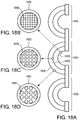
- NMSet or related device elements can also be arranged in one or more stages to achieve a greater pressure differential, for example as illustrated in Figures 18A-18D.
- Figure 18A illustrates a cross sectional view of a an array of staged NMSet or related devices arrangements 1800.
- Each staged arrangement 1800 is composed of stages 1810, 1820, 1830 of in the form of concentric half-spheres containing arrays of NMSet or related devices 1840, 1850, 1860 illustrated in blow-up in Figures 8B-18D .
- Individual NMSet apertures 1845, 1855, 1865 in each stage increase in size in accordance with the decreasing ambient pressure that would be experience at each subsequent stage in operation.
- Box 300 comprises two planar hot walls 302 parallel to each other, and two planar cold walls 301 parallel to each other and perpendicular to the walls 302. If the box 300 is comparable in size to the mean free path of the gas particles therein and the walls 301 and 302 are perfectly specular, the gas particles can reach thermal equilibrium with the cold walls 301 and the hot walls 302 independently. This is because surface normals of the walls are only shared between the two cold walls 301 or between the two hot walls 302, but not between a hot wall 301 and a hot wall 302.
- Knudsen numbers are usually not perfectly specular.
- specular surface properties exist very strongly in some materials so that there are angles for which convective flows in corners may be reduced. This effect is generally observed when the Knudsen numbers are large, which is a preferred condition for NMSet and related devices, particularly in nanoscale embodiments.
- the Knudsen number (Kn), named after Danish physicist Martin Knudsen (1871-1949), is a dimensionless number defined as the ratio of the molecular mean free path to a representative physical length scale.
- the representative physical length scale is taken to be the order of magnitude of the aperture diameter of the device, i.e.
- the representative physical scale length is a nanometer if the aperture is measured in nanometers and a micrometer if the aperture is measured in micrometers.
- the Knudsen number is preferably greater than 0.1, or greater than 1, or greater than 10.
- a simulation can be represented in the following table:
- a perturbation model M is evolved through a number (k) of iterations.
- M is initialized to an empty set, indicating no solution knowledge.
- a loop is started in which the search parameters generate an arbitrary element from the definite search space P and the prior learned knowledge M is used to perturb P.
- the specific algorithm used to perturb as an implementation detail.
- the Monte-Carlo simulation can be run with periodic bounds in all axes.
- particles encountering the periodic bound are stochastically thermostatted according to temperature and pressure settings in order to simulate ambient conditions.
- particle velocities are unmodified in order to simulate a periodic ensemble of identical device assemblies along that direction.
- the simulation may be run in two dimensions to reduce the computational complexity of the simulation.
- a three dimensional simulation should give similar results where the modeled device has cylindrical symmetry. Note that in general, a simulator does not have to use the periodicity as indicated here and may not specify any boundaries at all; they are only defined as a computational convenience.
- potential device geometries can be evaluated in consideration of the conditions under which a device will be used and known surface reflection properties of the material from which it will be constructed. Geometrical parameters can be optimized by analyzing results from simulation before the geometry is actually used in manufacture of NMSet and related devices.
- Fig. 19 shows an embodiment of an NMSet or related device 1900 with a straight geometry.
- the device 1900 comprises a hot layer 1902 and a cold layer 1901.
- the terms "hot layer” and “cold layer” mean that these layers have a temperature difference therebetween, not that the "hot layer” is necessarily hotter or the “cold layer” is necessarily colder, than a gas the NMSet or related device is immersed in.
- At least one straight through hole 1910 extends through all layers of the device 1900 and preferably has the same cross-sectional shape and size on each layer.
- the straight through hole 1910 can have any cross-sectional shape such as circular, slit, and comb.
- a total length 1910L (i.e. a distance from one entrance to the other entrance) of the straight through hole 1910 is up to 10 times, up to 5 times or up to 2 times of the mean free path of a gas in which the device 1900 is immersed.
- the mean free path of air at the standard atmosphere pressure is about 55 nm. At higher altitude, the mean free path of air increases.
- the total length 1910L is preferably not greater than 1500 nm.
- a temperature differential between the hot layer 1902 and the cold layer 1901 is preferably at least 30 °C, more preferably at least 50 °C, and most preferably at least 100 °C.
- the hot layer 1902 and the cold layer 1901 may be separated by a gap therebetween for thermal isolation.
- the gap preferably is a vacuum gap and/or contains a thermal insulator.
- the gap contains a plurality of thin pillars made of a good thermal insulator such as silicon dioxide.
- the device 1900 has preferably at least 10 straight through holes per square centimeter.
- a total perimeter length of all the straight through holes of the device 1900 per square centimeter is preferably at least two centimeters.
- Fig. 7 shows an embodiment of an NMSet or related device 700 with a parabolic geometry.
- alternating hot layers 702 and cold layers 701 are stacked.
- each hot layer 702 and cold layer 701 has a straight through hole. All the holes are aligned.
- the hole in each hot layer 702 has the same size as the hole in the cold layer 701 immediately above, and is smaller than the hole in the cold layer 701 immediately below.
- Each cold layer 701 is colder than its immediate adjacent hot layers 702 and each hot layer 702 is hotter than its immediate adjacent cold layers 701.
- a surface 702a of each hot layer 702, which has a surface normal in the -y direction, is exposed.
- All the holes collectively form a nozzle with a contour of a parabolic surface. This geometry minimizes shared bases between the hot and cold layers.
- an NMSet or related device does not necessarily increase the energy of the gas, the increasing hole diameter results in a drop in gas pressure. This can create strong vortexes near the lower aperture, which lower total efficiency.
- An NMSet with the parabolic geometry can be adiabatic or isobaric, but not both.
- An approximation of gas flow in an NMSet or related device with the parabolic geometry is shown in Fig. 8 . The momentum space of the gas is skewed such that the expectation value of the momentum points to the -y direction.
- the NMSet with the parabolic geometry may not suffer in its efficiency from the gas undergoing a change in volume, as long as the amount of heat added to the gas is sufficient to prevent the formation of vortexes.
- a device suffers in its efficiency from higher total entropy, i.e. the eigenvectors of the momentum space of the gas are not as far apart if the gas has to expand, but supplying heat at small scales is typically easier than carrying it away.
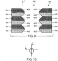
- the triangular geometry detailed in Fig. 9 is a partial optimization of the parabolic geometry for adiabatic flows. In this case, the gas is not permitted to experience a sufficient expansion to trigger large-scale vortex generation. Furthermore, because the apertures do not change size, a triangular arrangement such as this one may be easily stacked.
- the momentum space of this triangular geometry is more efficiently biased, as is illustrated in Fig. 10 .
- the exposed hot and cold surfaces meet at a 90-degree angle, however, a source of inefficiency arises when particles carry heat back and forth between surfaces across the center gap.
- Fig. 9 shows a stack 900 of NMSet or related device with the triangular geometry.
- Each device in the stack 900 comprises a hot layer 902 and a cold layer 901 of equal thickness.
- the temperature differential between the cold and hot layers 901 and 902 can be established by any suitable means such as the Peltier effect.
- Each device has a through hole 903.
- Each though hole 903 has a 45° chamfer (9031 and 9032) on each entrance.
- the width of the chamfers 9031 and 9032 is from 1.40 to 1.42 times of the thickness of the cold and hot layers 901 and 902.
- the through holes 903 in all layers in the stack 900 are aligned.
- the temperatures of the hot layers 902 in a device in the stack 900 do not increase monotonically from one side of the stack to the other side. In general, the temperatures of the cold layers 901 in a device in the stack 900 do not decrease monotonically from one side of the stack to the other side.
- each cold layer 901 is colder than its immediate adjacent hot layers 902 and each hot layer 902 is hotter than its immediate adjacent cold layers 901.
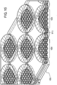
- Fig. 11 shows a stack 1100 of NMSet or related device with a sawtooth geometry.
- Each device in the stack 1100 comprises a hot layer 1102 with a thickness of t h and a cold layer 1101 with a thickness t c .
- the temperature differential between the cold and hot layers 1101 and 1102 can be established by any suitable means such as the Peltier effect.
- Each device has a through hole 1103.
- each through hole 1103 has a chamfer 11031 at the entrance on the side of the cold layer 1101, and a chamfer 11032 at the entrance on the side of the hot layer 11032.
- An angle between the chamfer 11031 and a center axis of the through hole 1103 is ⁇ 1 ; an angle between the chamfer 11032 and a center axis of the through hole 1103 is ⁇ 2 .
- the sum of ⁇ 1 and ⁇ 2 is preferably from 85° to 95°, more preferably from 88° to 92°.
- the ratio of t c to t h is substantially equal to the ratio of cotangent of ⁇ 1 to cotangent of ⁇ 2 .
- ⁇ 2 is preferably from 70° to 85°.
- the relationships of the chamfer angles described here are preferred limitations, not hard boundaries. In general for materials exhibit perfectly specular molecular reflection properties, the relationships of the chamfer angles can be slightly relaxed. For materials exhibit less than perfectly specular molecular reflection properties, the relationships shall be stringent.
- the chamfer geometries are preferably arranged so as to minimize shared bases.
- the surface normals of the specularly reflecting chamfer surfaces can thus preferably be orthogonal. Deviations from orthogonality can incur a penalty in efficiency as a cosine function. For engineering reasons, the hot and cold surfaces of the sawtooth arrangement may not come to a fine point.
- the through holes 1103 in all layers in the stack 1100 are aligned. Temperatures of the hot layers 1102 in each device in the stack 1100 do not increase monotonically from one side of the stack to the other side. Temperatures of the cold layers 1101 in each device in the stack 1100 do not decrease monotonically from one side of the stack 1100 to the other side. Each cold layer 1101 is colder than its immediate adjacent hot layers 1102 and each hot layer 1102 is hotter than its immediate adjacent cold layers 1101.
- the sawtooth geometry shown in Fig. 11 offers an improvement over the triangular geometry in that all hot layers 1102 are preferably oriented in nearly the same direction (i.e. ⁇ 2 is preferably nearly 90°). This reduces direct interaction between hot and cold layers 1102 and 1101 across the through hole 1103, and improves overall efficiency.
- the sawtooth geometry is capable of reducing the entropy in the gas (and thereby causing it to do more work) more efficiently than the triangular geometry.
- the momentum space of this sawtooth geometry is more efficiently biased than the momentum space of the triangular geometry, as is illustrated in Fig. 12 .
- device slices on opposite sides of a cross section have a magnitude of 1 / 2 in the y axis because their separation angle 90 degrees. This limits the efficiency of entropy reduction, as some of the entropy is going to neutralized in direct inter-surface interaction.
- the hot layers 1102 not only share no basis with the adjacent cold layers 1101, but also share very little basis with hot and cold layers across the through hole 1103. This combined property makes the sawtooth geometry more efficient than the triangular geometry.
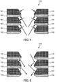
- Fig. 4 shows net forces the layers of the stack 1100 (sawtooth geometry) experience.
- a vacuum is generated at the entrance aperture (upper aperture in Fig. 4 ) which in turn generates a corresponding low-pressure region above the stack 1100, and a high-pressure region below the stack 1100.
- Gas particle velocities of the stack 1100 resulting from the gas pressure distribution are shown in Fig. 5 .
- each element in the device geometry acts both as a particle director and as the entropy reducer.
- the hot and cold plates are made of materials with different Peltier coefficients. Electrical current is made to flow between the cold and hot plates. This flow of current carries with it Peltier heat, establishing the temperature differential necessary to operate the device.
- piezoelectric spacers can be disposed between device elements to maintain the separation gaps therebetween.
- An NMSet or related device with the internal Peltier arrangement can make it easier to reduce the size of the device.
- a single stack such as the one shown in Fig. 14 can be fully functional to generate thrust.
- the temperature differential can be generated by field-enhanced thermionic emission.
- an electrical field can be established between the layers 1901 and 1902 such that charge carriers thermally emitted from the cold layer 1901 carry heat from the cold layer 1901 to the hot layer 1902.
- the temperature differential can be generated by a Peltier device external to an NMSet or related device.
- This Peltier device (not shown) is thermally coupled to an NMSet or related device stack 1500 via interface layers 1510 and 1520 as detailed in Figs. 15 and 16 .
- a device with an external Peltier device has the benefit of separating the materials used to generate fluid flow from the materials used to generate the temperature differential. From an engineering standpoint this may be desirable, as the materials suitable for a Peltier device may not be suitable for microstructures, or vice versa.
- an external Peltier device can be made larger and more efficient, and do not require high current to establish sufficient temperature differential.
- Piezoelectric spacers can be used between layers.
- Materials suitable for use in an NMSet preferably are strong enough to mechanically withstand thermal expansion and contraction, and/or preferably have very small expansion coefficients. Otherwise, holes in the layers could become misaligned, which could reduce efficiency.
- a temperature differential is established by any suitable heat source and/or heat sinks.
- the heat sources might be resistive heaters, chemical reaction, combustion, and/or direct illumination of bright light.
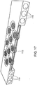
- An illustration of such an embodiment is shown in Fig. 17 .
- a heating surface 1702 can be resistive heating material, or a material that can efficiently receive radiative heating.
- the external non-Peltier arrangement is convenient because it does not require a Peltier device. For some applications, it may be convenient to direct the heating surface towards a source of radiation, such as the sun, rather than first converting radiation into electricity and drive a Peltier device.
- a source of radiation may be directed toward a heat absorbing surface in thermal communication with the hot layer of an NMSet or related device.
- care is preferably taken to ensure that the NMSet or related device does not overheat.
- the capillaries 1750 illustrated in Fig. 17 provide an exemplary mechanism by which a heat sink could be provided; however, it is also possible for the heat sink to simply be a series of vanes, or any other suitable heat sinks.
- the external non-Peltier arrangement in Fig. 17 could be configured to provide a heat source through the capillaries 1750.
- the heat source can be an exothermic chemical reaction, preferably one that does not generate too much pressure.
- NMSet and related devices may be constructed of a wide range of materials. In various aspects, properties of materials may be exploited in combination with desirable geometries.
- Specular reflection of gas molecules is a preferred property of the materials which form the gas-exposed surfaces of an NMSet or related device, e.g. the heated and cooled surfaces which are in contact with flowing gas. Specular reflection is the mirror-like reflection of light, or in this case gas particles, from a surface. On a specular surface, incoming gas particles at a single incident angle is reflected from the surface into a single outgoing angle. If the incoming gas particles and the surface have the same temperature, the incident angle and the outgoing angle with respect to the surface normal are the same. That is, the angle of incidence equals the angle of reflection.
- a second defining characteristic of specular reflection is that incident, normal, and reflected directions are coplanar. If the incoming gas particles and the surface are not at the same temperature and the reflection is diabatic (i.e. with heat exchange between the gas particles and the surface), the angle of reflection is a function of heat transferred between the surface and the gas particles.
- the degree of specularity of a material may be represented by a reflection kernel (such as the Cercignani-Lampis kernel) which is defined as the probability density function of reflected state of the gas particles per unit volume of the phase space. Details of the reflection kernel are disclosed in " Numerical Analysis of Gas-Surface Scattering Effect on Thermal Transpiration in the Free Molecular Regime", Vacuum, Vol. 82, Page 20-29, 2009 , and references cited therein.
- a reflection kernel such as the Cercignani-Lampis kernel
- Individual hot and cold layers may also be constructed of one or more structural elements which can comprise structural materials, e.g. a means for conferring rigidity, thermal conductive material, e.g. a means for heat transfer to and from a temperature differential generating means, and atomic reflection material, e.g. means for providing a desirable reflection kernel properties.
- structural materials e.g. a means for conferring rigidity
- thermal conductive material e.g. a means for heat transfer to and from a temperature differential generating means
- atomic reflection material e.g. means for providing a desirable reflection kernel properties.
- individual hot and cold layers may be constructed of layered composites of such materials.
- materials suitable for construction of an NMSet or related device can include titanium, silicon, steel, and/or iron. Titanium is light weight and possesses a hexagonal crystalline structure. Interfaces of titanium may be created at orthogonal angles without crystalline warping and therefore no stress limit. Material costs of titanium are high. Silicon is inexpensive and has well understood properties and processes for machining. The crystalline structure of silicon is diamond cubic. Steel is cheaper than titanium, possesses a cubic crystalline structure, is highly resistant to gaseous intrusion. Iron is cheaper than steel and has a crystalline form which makes it suitable for application in NMSet and related devices.
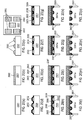
- a method of manufacturing an NMSet or related device comprises: (a) providing a suitable substrate 2001 such as amorphous silicon, crystalline silicon, ceramic, etc., the substrate preferably having a thickness of 500 to 1500 microns; (b) depositing a first layer 2002, such as silicon dioxide, the first layer 2002 preferably having a thickness of 200 nm to 50 microns; (c) forming discrete islands in any suitable shape such as strip, square, circle from the first layer 2002 by photolithography and etching the first layer 2002; (d) depositing a second layer 2003 over the discrete islands, the second layer 2003 being an electrical conductor such as Al, Nb or Zn; (e) depositing a third layer 2004 over the second layer 2003, the third layer 2004 being an electrical insulator such as silicon dioxide; (f) partially removing the third layer 2004 until the first layer 2002 is exposed; (g) depositing a fourth layer 2005, the fourth layer 2005 being an electrical insulator such as silicon dioxide, the fourth
- a method of manufacturing an NMSet or related device comprises: (a) providing a suitable substrate 2101 such as amorphous silicon, crystalline silicon, ceramic, etc., the substrate preferably having a thickness of 500 to 1500 microns; (b) depositing a first layer 2102, such as silicon dioxide, the first layer 2102 preferably having a thickness of 50 nm to 1000 nm; (c) depositing a second layer 2103 over the first layer 2102, the second layer 2103 being an electrical conductor such as Al, Nb or Zn and preferably having a thickness of 50 to 150 nm; (d) depositing a third layer 21w04 over the second layer 2103, the third layer 2104 being an electrical insulator such as silicon dioxide and preferably having a thickness of 50 to 100 nm; (e) depositing a fourth layer 2105 over the third layer 2104, the fourth layer 2105 being an electrical conductor such as Pt, Ni or Cu and preferably having a thickness of 50
Description
- This application is related to
U.S. Provisional Application Nos. 61/239,446, filed September 3, 2009 61/264,778, filed November 27, 2009 61/296,198, filed January 19, 2010 - The invention relates to methods and apparatus for causing the movement of fluids, for example gases, which may be applied to propulsion systems, vacuum generation, gas compression, and other uses.
- Devices for the movement of gases are widely utilized. The very first aircraft engines were piston driven propellers. They worked by coupling a piston engine to a propeller. Their simplicity lead to widespread adoption until jet engines were invented. Turbojet engines work by the principle of coupling a turbine to a fuel combination system. Spinning of the turbine compresses a fuel-air mixture which, when burned, provides thrust and torque to rotate the turbine. The first turbojet engines derived their thrust from exhaust leaving the engines. Modern variants of the turbojet engines include turbo prop and turbofan engines, which use torque generated by the exhaust to drive a propeller or fan in addition to compressing the fuel-air mixture. Rocket engines are possibly one of the oldest mechanical propulsion systems, and have not changed much since their inception. A rocket comprises a tube or cone in which sits (or into which is fed) a fuel oxidizer mixture. Expanding gas from combustion of this mixture creates thrust. Rockets, while offering the highest fuel-thrust ratio of any existing propulsion systems, cannot easily vary the amount of thrust they generate. Even adding an ability to turn a rocket on or off significantly complicates its design.
- Adhesion between two materials may be characterized into five types: mechanical, chemical, dispersive, electrostatic, and diffusive. Out of these five types, so far, only electrostatic and certain types of mechanical adhesion are easily reversible processes. Vacuum may be used to adhere surfaces and lift materials. However, such devices generally require separate mechanisms for generating a reduced pressure and applying the vacuum to a surface.
- Generally, the conventional propulsion systems mentioned above can also be used to compress gas. It is also possible to compress gas via the ideal gas law, such as in piston or diaphragm pumps. Current devices generally require pumping apparatuses separate from a pressurized vessel.
- The ability of temperature differential to drive gas flow at a surface has long been known. In 1873, Sir William Crookes developed a radiometer for measuring radiant energy of heat and light. Today, Crookes's radiometer is often sold as a novelty in museum stores. It consists of four vanes, each of which is blackened on one side and light on the other. These are attached to a rotor that can turn with very little friction. The mechanism is encased inside a clear glass bulb with most, but not all, of the air removed. When light falls on the vanes, the vanes turn with the black surfaces apparently being pushed by the light.
- Crookes initially explained that light radiation caused a pressure on the black sides to turn the vanes. His paper was refereed by James Clerk Maxwell, who accepted the explanation as it seemed to agree with his theories of electromagnetism. However, light falling on the black side of the vanes is absorbed, while light falling on the silver side is reflected. This would put twice as much radiation pressure on the light side as on the black, meaning that the mill is turning the wrong way for Crooke's initial explanation to be correct. Other incorrect explanations were subsequently proposed, some of which persist today. One suggestion was that the gas in the bulb would be heated more by radiation absorbed on the black side than the light side. The pressure of the warmer gas was proposed to push the dark side of the vanes. However, after a more thorough analysis Maxwell showed that there could be no net force from this effect, just a steady flow of heat across the vanes. Another incorrect explanation that is widely put forward even today is that the faster motion of hot molecules on the black side of the vane provide the push.
- The correct explanation for the action of Crookes radiometer derives from work that Osborne Reynolds submitted to the Royal Society in early 1879. He described the flow of gas through porous plates caused by a temperature difference on opposing sides of the plates which he called "thermal transpiration." Gas at uniform pressure flows through a porous plate from cold to hot. If the plates cannot move, equilibrium is reached when the ratio of pressures on either side is the square root of the ratio of absolute temperatures. Reynold's paper also discussed Crookes radiometer. Consider the edges of the radiometer vanes. The edge of the warmer side imparts a higher force to obliquely striking gas molecules than the cold edge. This effect causes gas to move across the temperature gradient at the edge surface. The vane moves away from the heated gas and towards the cooler gas, with the gas passing around the edge of the vanes in the opposite direction. Maxwell also refereed Reynolds' paper, which prompted him to write own paper, "On stresses in rarefied gases arising from inequalities of temperature." Maxwell's paper, which both credited and criticized Reynolds, was published in the Philosophical Transactions of the Royal Society in late 1879, appearing prior to the publication of Reynold's paper. See, Philip Gibbs in "The Physics and Relativity FAQ," 2006, at math.ucr.edu/home/baez/physics/General/LightMill/light-mill.html.
- Despite the descriptions by Reynolds and Maxwell of thermally driven gas flow on a surface dating from the late 19th century, the potential for movement of gases by interaction with hot and cold surfaces has not been fully realized. Operation of a Crookes radiometer requires rarefied gas (i.e. a gas whose pressure is much less than atmospheric pressure), and the flow of gas through porous plates does not yield usable thrust, partially due to the thickness and due to the random arrangement of pores in the porous plates.
-
US 2006/001569 A1 discloses a propulsion system for flying, floating, and ground vehicles that operates in an atmosphere under standard conditions according to radiometric principles. A hot surface is insulated from the cold one by means of one or more layers of thermally insulating materials sandwiched between the surfaces. Two parallel membranes are visible (FIG. 11 inUS 2006/001569 A1 ). The membranes have holes spaced apart by solid material. - An apparatus operable to propel a gas is described. In some embodiments, the apparatus comprises a plurality of layers arranged in a stack and a means of heating and/or cooling adjacent layers to form alternating hot and cold layers, and at least one through hole in the stack. In some embodiments, each hot layer is hotter than the immediately adjacent cold layers and each cold layer is colder than the immediately adjacent hot layers. A surface of each hot layer is exposed in an interior of the through hole, and a surface of each cold layer is exposed in the interior of the through hole.
- In other embodiments, the apparatus comprises at least a first and second layer and a means of heating and/or cooling adjacent layers to form alternating hot and cold layers, and at least one hole through the hot and cold layers. Each hot layer has a chamfer facing inward and in a first direction. An angle between the chamfer of each hot layer and a center axis of the through hole is designated θ2. Also, each cold layer has a chamfer facing inward and in a second direction opposed to the first direction. An angle between the chamfer of each cold layer and the center axis of the through hole is designated θ1. In some embodiments, the sum of θ1 and θ2 falls in the range from about 85° to 95°.
-
-
Fig. 1 shows a Peltier slab. -
Fig. 2 shows gas flow patterns around the Peltier slab ofFig. 1 . -
Fig. 3 shows a gas confined in a square box with parallel hot walls and parallel cold walls. -
Fig. 4 shows net forces on a stack of NanoMolecular Solid State Electrodynamic Thrusters (NMSets) with sawtooth geometry. -
Fig. 5 shows gas particle velocities around a stack of NMSets with sawtooth geometry. -
Fig. 6 shows the thermo-tunneling enhanced Peltier effect. -
Fig. 7 shows a stack of NMSets with a parabolic geometry. -
Fig. 8 shows gas flow patterns around the stack of NMSets ofFig. 7 and the momentum space of the gas. -
Fig. 9 shows a stack of NMSets with a triangular geometry. -
Fig. 10 shows the momentum space of the gas around the stack of NMSets with a triangular geometry. -
Fig. 11 shows a stack of NMSets with a sawtooth geometry. -
Fig. 12 shows the momentum space of the gas around the stack of NMSets with a sawtooth geometry. -
Fig. 13 shows a cross sectional view of an NMSet with an internal Peltier arrangement. -
Fig. 14 shows a perspective view of the NMSet with an internal Peltier arrangement onFig. 13 . -
Fig. 15 shows a perspective view of an NMSet with an external Peltier arrangement. -
Fig. 16 shows a cross sectional view of the NMSet with an external Peltier arrangement ofFig. 15 . -
Fig. 17 shows a perspective view of an NMSet with an external non-Peltier arrangement. -
Fig. 18 shows a cross sectional view of a staged NMSet arrangement. -
Fig. 19 shows an NMSet with a straight geometry. -
Fig. 20 shows an exemplary method of manufacturing an NMSet. -
Fig. 21 shows another exemplary method of manufacturing an NMSet. - In preferred embodiments, the apparatus described here may be referred to as a Nanomolecular Solid State Electrodynamic Thruster (NMSet). The basis of operation of NMSet makes it possible to apply an NMSet in the fields of propulsion, adhesion, and refrigeration, depending on the manner in which an NMSet is employed. In preferred embodiments, NMSets and related devices provide lightweight, compact, energy-efficient creation of a gas pressure differential with adjustable flow velocity.
- In some embodiments, NMSet can offer one or more of the following improvements in the field of propulsion:
- 1. Improved Resiliency: Damage to any area in a conventional propulsion system would probably lead to system-wide failure. An NMSet provides enhanced redundancy and robustness.
- 2. Lightweight: An NMSet does not need a particular fuel, so fuel load vanishes.
- 3. Scalability: Conventional propulsion systems cannot be easily scaled: optimal turbojets for small aircrafts are not scale reductions of optimal turbojets for large aircrafts.
- 4. Response Time: Thrust from an NMSet can be easily adjusted in response to changes of need.
- 5. Power Independence: Conventional propulsion systems require a specific type or class of fuels in order to operate, whereas an NMSet only requires a source of temperature differential, which can generated by electricity.
- 6. Green Propulsion: Because an NMSet does not have to rely on fossil fuels to operate, it does not produce polluting exhaust (e.g. carbon monoxide, nitrogen oxide) during ordinary operation.
- In some embodiments, an NMSet device may be used as a lightweight mechanical adhesive. The process can be reversible as the only step required to reverse the adhesion is to cut power to the NMSet. Using an NMSet can provide further benefit over electrostatic adhesion in that an NMSet does not require a material to be adhered to be flat or conductive. Compared to other mechanical adhesion processes, using an NMSet may not require a surface being adhered to be pretreated.
- Because an NMSet device can be arranged to drive gas flow through a surface, all or part of a pressurized vessel may function to provide gas compression. Thus, in some arrangements, separated pumping and pressurized containment may not be required. Moreover, because, an NMSet's action generally occurs over a short distance, it is possible, in some embodiments, to use an NMSet as a highly compact compressor by stacking multiple stages of NMSets. Conventional propulsion systems generally operate over length scales of centimeters and sometimes meters. Thus, stacking conventional propulsion systems tends to be a complex and expensive proposition By contrast, an NMSet can operate over micrometers. Furthermore, the versatility of an NMSet means that an NMSet can be readily adapted to function as a high pressure pump, a standard atmospheric pump, or with a sufficient number of stages, as a high vacuum pump.
- In one aspect, an NMSet and the related devices described here may be thought of as functioning by reducing entropy in gas in contact with the NMSet. Optionally, a device may add energy, e.g. thermal energy, to the gas. In another aspect, the geometry of the NMSet can affect gas flow direction and convenience of use. NMSet and related devices may be distinguished from previous thermal transpiration devices and the like by the combined application of scale parameters, materials having advantageous molecular reflection properties, geometries, and/or arrangement of elements that provide significant increased in efficiency. Described herein are various exemplary embodiments of NMSets with discussion of these and other parameters that, in preferred embodiments, can create a strong gas flow in a particular direction with minimal thermodynamic loss.
- Reduction of entropy in a gas by an NMSet may be represented by a transformation A in the momentum space k of the gas. A can be expressed in a matrix once a set of suitable bases is chosen for the momentum space k. If the expectation value of the transformed momentum space Ak is nonzero, the NMSet experiences a net momentum in the opposite direction of the expectation value due to the conservation of momentum.
- The geometry of an NMSet may be optimized for efficient functioning. The geometry of the NMSet will affect the transformation matrix A. A geometry that produces a matrix A essentially equal to an identity matrix I does not create a net momentum bias (i.e. will not make the transformed momentum space Ak have a nonzero expectation value). Rather, gas vortexes may be generated. Geometries that result in larger eigenvalues of A tend to imply a more efficient function, e.g. that more momentum is carried by gas particles moving in a particular direction.
- As an example, consider a
Peltier slab 100 immersed in a gas, shown inFig. 1 . ThePeltier slab 100 comprises anupper layer 101 and alower layer 102. For simplicity, a Cartesian coordinate system can be referenced with a y axis pointing from thelower layer 102 to theupper layer 101. A temperature differential can be established by a Peltier device (not shown) between the layers or any suitable means such that theupper layer 101 is colder than the gas and thelower layer 102 is hotter than the gas. While not wanting to be limited to any particular theory, the Peltier effect does not appear to transfer net heat into the gas, transformation caused by thePeltier slab 100 to the momentum space k of the gas can be expressed by a Hermetian matrix A. When a gas particle (molecule or atom) collides with thelower layer 102, assuming the collision is diabatic, the gas particle bounces off at a higher velocity than before the collision. When a gas particle collides with theupper layer 101, assuming the collision is diabatic, the gas particle bounces off theupper layer 101 at a lower velocity than before the collision. ThePeltier slab 100 feels a net force pointing thelower layer 102 from to theupper layer 101, i.e. a net force in the y direction. In another word, thelower layer 102 heats and thus increases pressure of the gas below thelower layer 102, while theupper layer 101 cools and thus decreases the pressure of the gas above theupper layer 101. The pressure difference drives thePeltier slab 100 upward. In terms of transformation of the momentum space k of the gas, as gas particles bouncing from theupper layer 101 leave with less momentum than gas particles bouncing from thelower layer 102, the transformed momentum space Ak becomes skewed preferentially in the -y direction, i.e. the expectation value p of the transformed momentum space Ak is nonzero and points to the -y direction. Assuming the gas and thePeltier slab 100 compose a closed system (i.e. no interaction with other objects), thePeltier slab 100 gains a momentum -p to conserve the total momentum of the closed system. - While the geometry of the
Peltier slab 100 inFig. 1 does generate lift, the reason it cannot be used practically for the following reasons: - 1. If the
Peltier slab 100 is large, translational motion of thePeltier slab 100 along the y direction forces the gas to flow all the way around edges of the Peltier slab. - 2. The vast majority of the heat is transferred from surfaces of the
Peltier slab 100 via gas convection. - 3. Gas near the surfaces has an insulating effect. Momentum transfer between the
Peltier slab 100 and the gas is not efficient except in proximity of the edges of the slab, as shown inFig. 2 . - 4. Surface area of the
Peltier slab 100 is surface area of its convex hull. - These problems all relate to a single core issue, very little of the gas has any direct surface contact. Thus, a more complex geometry can be advantageous. Exemplary embodiments with three different geometries are described hereinbelow.
- Although many different geometries of NMSet or related devices are possible, the principle of operation of NMSets remains the same. While not wanting to be limited to any particular theory, operation uses energy to lower entropy on some device surfaces and transfer lowered entropy to a gas in contact with the surface. The device can optionally donate energy to the gas by raising the gas temperature. The function of the NMSet may be therefore divided into three areas: the means by which entropy on surfaces of the device is lowered, the means by which the lowered entropy is transferred to the gas, and the optional means by which the gas temperature is increased.
- A temperature differential between layers of material is generally required for a NMSet or related device to operate. In preferred embodiments described herein, a temperature differential can be established in a solid state electrodynamic mechanism, i.e. the "Se" of NMSet. However, the devices and methods described here are not limited to electronic or purely solid state devices. For example, a temperature differential may be established by conduction of heat from combustion using a fluid coolant, exothermic chemical reaction, or other chemical source. A temperature differential may be established by simple resistive heating, by the Peltier effect, by the thermo-tunneling enhanced Peltier effect, or by any other suitable means. A means by which the temperature differential is established between two objects can be phenomenologically described by two characteristics: entropy-reduction (heat transfer between the two objects), and diabaticity (total heat transfer between environment and the two objects).
- In one embodiment, the Peltier effect can be used to establish a temperature differential. The Peltier effect occurs when an electric current is applied through a loop composed of two materials with different Peltier coefficients joined at two junctions. Depending on the direction of the electric current, heat flows from one junction to the other, causing a temperature differential to be established between the junctions. The Peltier effect can be understood as follows: Heat capacity of charge carriers in a material is characterized by the Peltier coefficient Π, which is the amount of heat carried per unit charge carriers in the material. When an electric current I flows through a junction of material A with Peltier coefficients Π A and material B with Peltier coefficient Π B, the amount heat carried by charge carriers to the junction in a unit time is I×(Π A -Π B).
- The Peltier effect reduces entropy locally and is adiabatic. Assuming Joule heating can be ignored, in the Peltier effect, heat is transferred from one junction to another, but no heat is added into the loop of the two materials. This entropy reduction can provide for advantages in the stackability of NMSet and related devices. Consequently, the Peltier effect lends itself particularly well to some embodiments.
- In this embodiment, a power source drives an electric current between two surfaces. Charge carriers such as electrons and/or holes carry heat as they flow in the electric current, and thus create a temperature differential between the two surfaces. Entropy is reduced as the temperature differential is established.
- Phonon flow reduces the temperature differential established by the Peltier effect. If phonons are permitted to flow freely (i.e., infinite thermal conductivity or zero heat capacity), their flow will cancel the temperature differential established the Peltier effect. Efficiency of the Peltier effect can be increased by reducing electrical resistance and thermal conductance.
- One way to reduce thermal conductance is to place a narrow vacuum gap in the path of the electric current. Phonons cannot easily pass the vacuum gap but charge carriers can do so under a voltage across the vacuum gap. This is called thermo-tunneling enhanced Peltier effect (or thermotunnel cooling).
Fig. 6 shows a diagram of the thermo-tunneling enhanced Peltier effect.Charge carriers 601 can tunnel through avacuum gap 602. - The thermo-tunneling enhanced Peltier effect is generally only significant at high temperatures or voltages, unless enhanced by choice of surface geometry and materials that can restrict behavior of charge carriers near the vacuum gap and increase tunneling probability. For example, suitable surface coatings and structures can function as a filter that do not allow low energy states of charge carriers but only high energy states of charge carriers near the vacuum gap.
- In another embodiment, a temperature differential can be created and maintained by field-enhanced thermionic emission. Thermionic emission is a heat-induced flow of charge carriers over a potential-energy barrier. The charge carriers can be electrons or ions (i.e. thermions). In a simple approximation, the potential-energy barrier acts like a dam, in that it withholds carriers with thermal energy less than its height and allows carriers with thermal energy greater than its height to flow over. When the overflowing carriers pass the potential-energy barrier, heat is carried away with them. The carriers left behind the potential-energy barrier re-thermalize (redistribute in energy) to a lower temperature. Thermionic emission typically requires an operating temperature of several hundred degrees Celsius so that a non-negligible fraction of the carriers have thermal energies great enough to overcome the potential-energy barrier. An electrical field can assist thermionic emission by reducing the height of the potential-energy barrier and reducing the required operating temperature.
- A temperature differential in an NMSet or related device can also be established by using resistive heating and/or by suitable chemical processes. In order to maintain the temperature differential without raising the overall temperature of the device, some cooling means can also be provided, such as a heat sink exposed to atmosphere. No matter what cooling means is used, the temperature differential is more pronounced if warmer surfaces of the device are not cooled as efficiently as cooler surfaces, which can be achieved, for example, by thermal insulation.
- In one aspect, the production of net thrust may by thought of as the transfer of the reduced entropy from an established temperature differential to a gas. Without wishing to be bound by theory, consider a single device operating in a gas, as an adiabatic process. In this example, a temperature differential between a hot and a cold layer can be established by a suitable means such as the Peltier effect. For simplicity, assume no net heat transfer between the gas and the device. Particles of the gas will impact the hot and cold layers with equal probabilities, and their interaction with these layers will have consequences on local momentum space of the gas near surfaces of the hot and cold layers. The local momentum space of the gas very close to a surface of the hot and cold layers has nonzero expectation value when the gas and the surface have different temperatures. Assuming also that no gas particles penetrate the surface, the gas particles rebound from the surface with momenta different from their incident momenta, which skews the momentum space along the surface normal, and the magnitude of the skew is directly related to the temperature difference between the surface and the gas.
- In an arrangement with random geometry (i.e. surface normals at different surface locations point to random directions), the weighted sum of expectation values of local momentum spaces of the gas is nearly zero, which results in almost no net thrust. In an NMSet with an optimized geometry, however, the weighted sum of expectation values of local momentum spaces of the gas can be non-zero, which leads to a net thrust.
- A trivial example of an arrangement that has non-zero net thrust is shown in
Fig. 1 , as described above. This geometry is not very efficient because macroscopic convective gas flows and vortex formation increase the entropy and limit the amount of useful work. Exemplary convective gas flows 120, 130 are shown inFig. 2 . Gas atambient temperature 110 flows towards thecold layer 101 and gets cooled. Cooled gas flows 120 away from thecold layer 101 and around the edge of thePeltier slab 100 towards thehot layer 102. Heated gas flows 130 away from thehot layer 102. - To simplify the description, it may be helpful to think about the system in terms of Newton's second law and the kinetic theory of gases. Around the
Peltier slab 100 inFigs. 1 and 2 , assuming that temperature of the gas is bracketed by the temperatures of thelayers layer 101 leave thelayer 101 with greater momentum than before the collision. Similarly, gas particles that collide with thelayer 102 leave thelayer 102 with lesser momentum than before the collision. Since gas pressure is directly related to momenta of gas particles, gas near thelayer 102 has higher pressure than gas near thelayer 101. This pressure bias pushes theentire slab 100 in the y direction. - In another embodiment, the
Peltier slab 100 can have at least one through hole between thelayer layer 101 to thelayer 102 through the hole which enables higher heating rate of the gas. Such flow of gas is referred to as thermal transpiration. Assuming gas near thelayer 101 has temperature of Tc and pressure of Pc , and gas near thelayer 102 has temperature of Th and pressure of Ph, thermal transpiration causes the gas to flow from thelayer 101 to thelayer 102 through the hole, if the following equation is satisfied:
- In order to improve efficiency, it is helpful to understand where the classical limit exists within gas flows. Convective descriptions of gas flow break down at around length scales where the Knudsen number vanishes. As a result, in some aspects, the mean free path of a gas becomes a useful parameter in determining advantageous geometries of an NMSet.
- For instance, consider a gas at a particular pressure having a mean free path of 10nm. If a cloud of such gas is trapped in a two dimensional square 20nm by 20nm box as shown in
Fig. 3 , a gas particle, within 10nm of travel, will be approximately as likely to have struck another gas particle as it is to have struck the walls of the box. If the walls of the box are heated, then smaller boxes will reach thermodynamic equilibrium with gas therein faster than larger boxes, because gas particles in smaller boxes have more chances to collide with and exchange heat with the walls. Generally, when most of collisions in a gas are between gas particles and a surface, then thermodynamic equilibrium can be achieved approximately in the mean free time (the time it takes a gas particle to travel the mean free path). - For this reason, in some embodiments, the characteristic scale of individual features of NMSet and related devices may be nanoscale, i.e., the "NM" of NMSet. However, it must be understood that the methods and devices described here are not limited to nanoscale embodiments. The mean free path parameter is dependent on gas density so that in some embodiments and uses, larger scale features may be employed. Furthermore, as described herein, pluralities of NMSet and related device elements can be combined to provide action over a large surface. For example, NMSet or related devices may advantageously be arranged in arrays and arrays of arrays to provide directed movement of gas over across large surfaces, for examples as illustrated in
Figures 16 and17 . NMSet or related device elements can also be arranged in one or more stages to achieve a greater pressure differential, for example as illustrated inFigures 18A-18D. Figure 18A illustrates a cross sectional view of a an array of staged NMSet orrelated devices arrangements 1800. Each stagedarrangement 1800 is composed ofstages related devices Figures 8B-18D .Individual NMSet apertures - Interaction between surfaces can affect the momentum space transformation matrix A. If nearby surfaces can easily exchange phonons via gas particles, then the entropy at these surfaces will locally increase at a higher rate than surfaces which cannot easily exchange phonons via development of vortexes. This will generally reduce the efficiency of a system.
- One method by which phonon exchange may be reduced is to limit or eliminate any shared bases between surfaces. For instance, consider gas particles in the
box 300 inFig. 3 .Box 300 comprises two planarhot walls 302 parallel to each other, and two planarcold walls 301 parallel to each other and perpendicular to thewalls 302. If thebox 300 is comparable in size to the mean free path of the gas particles therein and thewalls cold walls 301 and thehot walls 302 independently. This is because surface normals of the walls are only shared between the twocold walls 301 or between the twohot walls 302, but not between ahot wall 301 and ahot wall 302. Consequently, no momentum can be exchanged between thehot walls 302 and thecold walls 301 by the gas particles. This is because interaction between the gas particles and thecold walls 301 only affect momenta in the x direction but not momenta in the y direction; and interaction between the gas particles and thehot walls 302 only affect momenta in the y direction but not momenta in the x direction and the fact that momenta in the x direction are orthogonal with momenta in the y direction. After thermal equilibrium is reached between the gas particles and the walls, the gas particles move faster in the x direction than in the y direction. - As a practical matter, surfaces are usually not perfectly specular. However, specular surface properties exist very strongly in some materials so that there are angles for which convective flows in corners may be reduced. This effect is generally observed when the Knudsen numbers are large, which is a preferred condition for NMSet and related devices, particularly in nanoscale embodiments. The Knudsen number (Kn), named after Danish physicist Martin Knudsen (1871-1949), is a dimensionless number defined as the ratio of the molecular mean free path to a representative physical length scale. In an NMSet or the related devices discussed here, the representative physical length scale is taken to be the order of magnitude of the aperture diameter of the device, i.e. the representative physical scale length is a nanometer if the aperture is measured in nanometers and a micrometer if the aperture is measured in micrometers. In preferred methods of using the devices disclosed herein the Knudsen number is preferably greater than 0.1, or greater than 1, or greater than 10.
- Performance of an NMSet with a specific geometry can be simulated by a Monte-Carlo method for optimization. Specifically, a simulation for an NMSet or related device with any given geometry starts with a group of gas particles with random initial positions and momenta around the device. Positions and momenta of these particles after a small time interval are calculated from the initial positions and momenta, using known physical laws, parameters such as temperature, pressure, chemical identity, geometry of the device, interaction between surfaces of the device and the gas particles. The simulation is run through a chosen number of iterations and simulation results are analyzed. The geometry of the device can be optimized using simulation results. In preferred embodiments, a device is constructed using the results of the simulation analysis.
- In a preferred embodiment, a simulation can be represented in the following table:
Algorithm 1 EVOLVE MODEL(M, P, k)
      M←0
      P←a set of search parameters
      k←number of iterations
     for i=1 to k do
             V←An instance of P
             V←V perturbed by M
             E←MONTE CARLO(V)
             Update M using E
end for - 1. Molecular diagrams, in some embodiments containing up to three atoms, such as CO2 or H2O.
- 2. Partial concentrations for constituent molecules.
- 3. Initial temperature and pressure of the entire gas.
Claims (14)
- An apparatus operable to propel a gas, comprising:at least a first layer and a second layer arranged in a stack (1100) and means for heating and/or cooling the first and second layers to form a hot layer (1102) and a cold layer (1101) wherein the cold layer has a lower temperature than the hot layer; and,at least one through hole (1103) in the stack;wherein:a surface of each hot layer is exposed in an interior of the through hole; anda surface of each cold layer is exposed in the interior of the through hole;an entire length of the through hole is up to 10 times of a mean free path of a gas in which the apparatus is immersed and/or is not greater than 1500 nm,characterized in that:each hot layer has a chamfer (11032) facing inward and in a first direction, an angle between the chamfer of each hot layer and a center axis of the through hole being θ2; andeach cold layer has a chamfer (11031) facing inward and in a second direction opposed to the first direction, an angle between the chamfer of each cold layer and the center axis of the through hole being θ1.
- The apparatus of claim 1, wherein means for heating and cooling the first and second layers is a Peltier device or a field-enhanced thermionic emission device.
- The apparatus of claim 2, wherein the Peltier device or the field-enhanced thermionic emission device is interposed between the first and second layers.
- The apparatus of claim 1, wherein a sum of θ1 and θ2 is from 85° to 95°.
- The apparatus of claim 4, wherein each hot layer has a thickness of th, each cold layer has a thickness of tc, and the ratio of th to tc is substantially equal to the ratio of cotangent of θ2 to cotangent of θ1.
- The apparatus of claim 1, wherein a gap is interposed between the hot and cold layers.
- The apparatus of claim 6, wherein the gap comprises spacer elements.
- The apparatus of Claim 1, wherein θ2 is from 70° to 85°.
- The apparatus of Claim 5, wherein tc is greater than th.
- An apparatus comprising a series of the apparatus of claim 1 wherein the series are arranged such that the hot layers and cold layers form an alternating stack of hot and cold layers, each hot layer is hotter than the immediately adjacent cold layers, each cold layer is colder than the immediate adjacent hot layers, and at least one through hole is aligned across the stack.
- Use of the apparatus of claim 1 comprising exposing the apparatus to a gas at an ambient temperature and pressure and activating the means of heating and/or cooling alternating layers to form alternating hot and cold layers such that the gas is propelled through the through hole.
- The use according to claim 11 wherein each hot layer is hotter than the ambient temperature of the gas and each cold layer is colder than the ambient temperature of the gas.
- The use according to claim 12 wherein the mean temperature of all the hot and cold layers is substantially the same as the ambient temperature of the gas.
- A method of manufacturing the apparatus of claim 1, comprising:running a simulation of an apparatus according to claim 1 having a specific selected starting geometric arrangement of through hole and layers, the simulation comprising initializing a group of simulated gas particles with random initial positions and momenta around a simulated apparatus, calculating positions and momenta of these particles after a small time interval from the initial positions and momenta using known physical laws, repeating the calculation through a chosen number of iterations, and analyzing the positions and momenta of the gas particles through the simulation,modifying the geometric arrangement of the device within a defined search space and running another simulation through a chosen number of iterations,identifying a geometric arrangement providing more efficient propulsion of gas particles through a simulated apparatus than the starting geometry;manufacturing an apparatus having the identified geometric arrangement.
Applications Claiming Priority (4)
| Application Number | Priority Date | Filing Date | Title |
|---|---|---|---|
| US23944609P | 2009-09-03 | 2009-09-03 | |
| US26477809P | 2009-11-27 | 2009-11-27 | |
| US29619810P | 2010-01-19 | 2010-01-19 | |
| PCT/US2010/002428 WO2011028287A2 (en) | 2009-09-03 | 2010-09-03 | Nanomolecular solid state electrodynamic thruster |
Publications (3)
| Publication Number | Publication Date |
|---|---|
| EP2473785A2 EP2473785A2 (en) | 2012-07-11 |
| EP2473785A4 EP2473785A4 (en) | 2015-04-29 |
| EP2473785B1 true EP2473785B1 (en) | 2018-06-13 |
Family
ID=43649846
Family Applications (1)
| Application Number | Title | Priority Date | Filing Date |
|---|---|---|---|
| EP10814092.2A Not-in-force EP2473785B1 (en) | 2009-09-03 | 2010-09-03 | Nanomolecular solid state electrodynamic thruster |
Country Status (9)
| Country | Link |
|---|---|
| US (3) | US9006612B2 (en) |
| EP (1) | EP2473785B1 (en) |
| JP (2) | JP2013504008A (en) |
| KR (1) | KR101714510B1 (en) |
| CN (1) | CN102639940B (en) |
| IL (1) | IL218425A (en) |
| IN (1) | IN2012DN02800A (en) |
| RU (1) | RU2535593C2 (en) |
| WO (1) | WO2011028287A2 (en) |
Families Citing this family (15)
| Publication number | Priority date | Publication date | Assignee | Title |
|---|---|---|---|---|
| WO2012118990A1 (en) | 2011-03-02 | 2012-09-07 | Game Changers, Llc | Apparatus and methods for evacuating air from a closed area |
| US9192882B2 (en) * | 2009-09-03 | 2015-11-24 | Game Changers Llc | Apparatus and methods using non-fouling bypass filter |
| WO2012119034A2 (en) * | 2011-03-02 | 2012-09-07 | Game Changers, Llc | Method and apparatus for a dynamic air cushion transport system |
| JP2014512294A (en) * | 2011-03-02 | 2014-05-22 | ゲーム・チェンジャーズ・リミテッド・ライアビリティ・カンパニー | Air cushion transport |
| WO2012118994A2 (en) * | 2011-03-02 | 2012-09-07 | Game Changers, Llc | Fault tolerant control system for distributed micro-thrusters |
| EP2681116A4 (en) * | 2011-03-02 | 2014-10-15 | Game Changers Llc | Flight control using distributed micro-thrusters |
| FR2972571A1 (en) * | 2011-03-09 | 2012-09-14 | St Microelectronics Crolles 2 | THERMOELECTRIC GENERATOR |
| EP2861859B1 (en) * | 2012-06-15 | 2018-03-21 | Game Changers, Llc | Micro thruster uses and improvements |
| WO2014160361A1 (en) * | 2013-03-14 | 2014-10-02 | Steinhour Leif Alexi | Convection pump and method of operation |
| US9683474B2 (en) | 2013-08-30 | 2017-06-20 | Dürr Systems Inc. | Block channel geometries and arrangements of thermal oxidizers |
| WO2016081047A2 (en) * | 2014-09-03 | 2016-05-26 | Pacific Scientific Energetic Materials Company | Propulsion system comprising plurality of individually selectable solid fuel motors |
| US9761781B2 (en) * | 2014-11-29 | 2017-09-12 | Hyundai Motor Company | Thermoelectric generator sleeve for a catalytic converter |
| AU2020281012B1 (en) * | 2020-12-01 | 2021-06-17 | Soliton Holdings Corporation, Delaware Corporation | Apparatuses Based on Jet-Effect and Thermoelectric Effect |
| WO2023039173A1 (en) * | 2021-09-09 | 2023-03-16 | Torramics, Inc. | Apparatus and method of operating a gas pump |
| US11767828B2 (en) | 2023-03-27 | 2023-09-26 | Daniel L. Amend | Light turbine, turbine, and turbine housing for vane evaluation |
Family Cites Families (13)
| Publication number | Priority date | Publication date | Assignee | Title |
|---|---|---|---|---|
| GB8609228D0 (en) * | 1986-04-16 | 1986-05-21 | Marconi Co Ltd | Thrusters |
| US6984273B1 (en) * | 1999-07-29 | 2006-01-10 | Aerojet-General Corporation | Premixed liquid monopropellant solutions and mixtures |
| US6378292B1 (en) * | 2000-11-10 | 2002-04-30 | Honeywell International Inc. | MEMS microthruster array |
| US6692700B2 (en) * | 2001-02-14 | 2004-02-17 | Handylab, Inc. | Heat-reduction methods and systems related to microfluidic devices |
| US6752601B2 (en) * | 2001-04-06 | 2004-06-22 | Ngk Insulators, Ltd. | Micropump |
| DE60213085T2 (en) * | 2001-05-23 | 2007-02-15 | Svenska Rymdaktiebolaget | REACTOR FOR THE DECOMPOSITION OF LIQUID MONERGOL FUELS ON AMMONIUM DINITIRID BASE AND DECOMPOSITION PROCESS |
| JP4766797B2 (en) | 2001-08-14 | 2011-09-07 | 株式会社東京精密 | Prober stage structure |
| DE10240639B3 (en) * | 2002-09-03 | 2004-02-12 | Trw Airbag Systems Gmbh & Co. Kg | Vehicle airbag gas generator with long cylindrical casing, has external igniter units producing gas which flows into distribution chambers in cylinder |
| US7069733B2 (en) * | 2003-07-30 | 2006-07-04 | Air Products And Chemicals, Inc. | Utilization of bogdown of single-shaft gas turbines to minimize relief flows in baseload LNG plants |
| WO2005068066A1 (en) | 2004-01-20 | 2005-07-28 | Sosho, Inc. | Temperature controller and protein crystallizer utilizing the same |
| US20060001569A1 (en) | 2004-07-01 | 2006-01-05 | Marco Scandurra | Radiometric propulsion system |
| US7690187B2 (en) * | 2006-09-26 | 2010-04-06 | The Aerospace Corporation | Modular micropropulsion device and system |
| US20090151434A1 (en) * | 2007-12-17 | 2009-06-18 | Samsung Electronics Co., Ltd | Apparatus and method using a disk drive slider and/or a peltier plate in an atomic force microscope |
-
2010
- 2010-09-03 CN CN201080049375.7A patent/CN102639940B/en not_active Expired - Fee Related
- 2010-09-03 WO PCT/US2010/002428 patent/WO2011028287A2/en active Application Filing
- 2010-09-03 EP EP10814092.2A patent/EP2473785B1/en not_active Not-in-force
- 2010-09-03 RU RU2012112828/06A patent/RU2535593C2/en not_active IP Right Cessation
- 2010-09-03 KR KR1020127007235A patent/KR101714510B1/en active IP Right Grant
- 2010-09-03 JP JP2012527867A patent/JP2013504008A/en active Pending
- 2010-09-03 IN IN2800DEN2012 patent/IN2012DN02800A/en unknown
-
2011
- 2011-03-02 US US13/039,238 patent/US9006612B2/en not_active Expired - Fee Related
-
2012
- 2012-03-01 IL IL21842512A patent/IL218425A/en not_active IP Right Cessation
- 2012-03-02 US US13/410,798 patent/US8794930B2/en not_active Expired - Fee Related
-
2014
- 2014-06-20 US US14/310,482 patent/US9845796B2/en not_active Expired - Fee Related
-
2016
- 2016-06-27 JP JP2016126718A patent/JP6218892B2/en not_active Expired - Fee Related
Non-Patent Citations (1)
| Title |
|---|
| None * |
Also Published As
| Publication number | Publication date |
|---|---|
| US20110240622A1 (en) | 2011-10-06 |
| KR20120079833A (en) | 2012-07-13 |
| CN102639940B (en) | 2014-08-06 |
| WO2011028287A2 (en) | 2011-03-10 |
| US20150247492A1 (en) | 2015-09-03 |
| IN2012DN02800A (en) | 2015-07-24 |
| JP2016188646A (en) | 2016-11-04 |
| US20120237364A1 (en) | 2012-09-20 |
| US9845796B2 (en) | 2017-12-19 |
| JP6218892B2 (en) | 2017-10-25 |
| KR101714510B1 (en) | 2017-03-09 |
| US8794930B2 (en) | 2014-08-05 |
| RU2012112828A (en) | 2013-10-10 |
| IL218425A (en) | 2014-07-31 |
| JP2013504008A (en) | 2013-02-04 |
| RU2535593C2 (en) | 2014-12-20 |
| EP2473785A2 (en) | 2012-07-11 |
| US9006612B2 (en) | 2015-04-14 |
| EP2473785A4 (en) | 2015-04-29 |
| IL218425A0 (en) | 2012-04-30 |
| WO2011028287A3 (en) | 2011-06-03 |
| CN102639940A (en) | 2012-08-15 |
Similar Documents
| Publication | Publication Date | Title |
|---|---|---|
| EP2473785B1 (en) | Nanomolecular solid state electrodynamic thruster | |
| US9528507B2 (en) | Distributed thrusters driven gas compressor | |
| US9340280B2 (en) | Flight control using distributed micro-thrusters | |
| US9728699B2 (en) | Thermal transpiration device and method of making same | |
| EP2681438B1 (en) | Fault tolerant control system for distributed micro-thrusters | |
| US9551293B2 (en) | Replaceable thrust generating structures attached to an air vehicle | |
| US9404487B2 (en) | Apparatus and methods for evacuating air from a closed area | |
| EP2861859B1 (en) | Micro thruster uses and improvements | |
| WO2012119036A1 (en) | An article separation system using a plurality of vortexes |
Legal Events
| Date | Code | Title | Description |
|---|---|---|---|
| PUAI | Public reference made under article 153(3) epc to a published international application that has entered the european phase |
Free format text: ORIGINAL CODE: 0009012 |
|
| 17P | Request for examination filed |
Effective date: 20120402 |
|
| AK | Designated contracting states |
Kind code of ref document: A2 Designated state(s): AL AT BE BG CH CY CZ DE DK EE ES FI FR GB GR HR HU IE IS IT LI LT LU LV MC MK MT NL NO PL PT RO SE SI SK SM TR |
|
| DAX | Request for extension of the european patent (deleted) | ||
| REG | Reference to a national code |
Ref country code: DE Ref legal event code: R079 Ref document number: 602010051318 Country of ref document: DE Free format text: PREVIOUS MAIN CLASS: F23R0003420000 Ipc: F03H0099000000 |
|
| A4 | Supplementary search report drawn up and despatched |
Effective date: 20150326 |
|
| RIC1 | Information provided on ipc code assigned before grant |
Ipc: H01L 35/00 20060101ALI20150320BHEP Ipc: F03H 99/00 20090101AFI20150320BHEP |
|
| GRAP | Despatch of communication of intention to grant a patent |
Free format text: ORIGINAL CODE: EPIDOSNIGR1 |
|
| INTG | Intention to grant announced |
Effective date: 20180103 |
|
| GRAS | Grant fee paid |
Free format text: ORIGINAL CODE: EPIDOSNIGR3 |
|
| GRAA | (expected) grant |
Free format text: ORIGINAL CODE: 0009210 |
|
| AK | Designated contracting states |
Kind code of ref document: B1 Designated state(s): AL AT BE BG CH CY CZ DE DK EE ES FI FR GB GR HR HU IE IS IT LI LT LU LV MC MK MT NL NO PL PT RO SE SI SK SM TR |
|
| REG | Reference to a national code |
Ref country code: GB Ref legal event code: FG4D |
|
| REG | Reference to a national code |
Ref country code: CH Ref legal event code: EP Ref country code: AT Ref legal event code: REF Ref document number: 1008778 Country of ref document: AT Kind code of ref document: T Effective date: 20180615 |
|
| REG | Reference to a national code |
Ref country code: IE Ref legal event code: FG4D |
|
| REG | Reference to a national code |
Ref country code: DE Ref legal event code: R096 Ref document number: 602010051318 Country of ref document: DE |
|
| REG | Reference to a national code |
Ref country code: NL Ref legal event code: MP Effective date: 20180613 |
|
| REG | Reference to a national code |
Ref country code: LT Ref legal event code: MG4D |
|
| PG25 | Lapsed in a contracting state [announced via postgrant information from national office to epo] |
Ref country code: BG Free format text: LAPSE BECAUSE OF FAILURE TO SUBMIT A TRANSLATION OF THE DESCRIPTION OR TO PAY THE FEE WITHIN THE PRESCRIBED TIME-LIMIT Effective date: 20180913 Ref country code: FI Free format text: LAPSE BECAUSE OF FAILURE TO SUBMIT A TRANSLATION OF THE DESCRIPTION OR TO PAY THE FEE WITHIN THE PRESCRIBED TIME-LIMIT Effective date: 20180613 Ref country code: SE Free format text: LAPSE BECAUSE OF FAILURE TO SUBMIT A TRANSLATION OF THE DESCRIPTION OR TO PAY THE FEE WITHIN THE PRESCRIBED TIME-LIMIT Effective date: 20180613 Ref country code: NO Free format text: LAPSE BECAUSE OF FAILURE TO SUBMIT A TRANSLATION OF THE DESCRIPTION OR TO PAY THE FEE WITHIN THE PRESCRIBED TIME-LIMIT Effective date: 20180913 Ref country code: ES Free format text: LAPSE BECAUSE OF FAILURE TO SUBMIT A TRANSLATION OF THE DESCRIPTION OR TO PAY THE FEE WITHIN THE PRESCRIBED TIME-LIMIT Effective date: 20180613 Ref country code: CY Free format text: LAPSE BECAUSE OF FAILURE TO SUBMIT A TRANSLATION OF THE DESCRIPTION OR TO PAY THE FEE WITHIN THE PRESCRIBED TIME-LIMIT Effective date: 20180613 Ref country code: LT Free format text: LAPSE BECAUSE OF FAILURE TO SUBMIT A TRANSLATION OF THE DESCRIPTION OR TO PAY THE FEE WITHIN THE PRESCRIBED TIME-LIMIT Effective date: 20180613 |
|
| PG25 | Lapsed in a contracting state [announced via postgrant information from national office to epo] |
Ref country code: LV Free format text: LAPSE BECAUSE OF FAILURE TO SUBMIT A TRANSLATION OF THE DESCRIPTION OR TO PAY THE FEE WITHIN THE PRESCRIBED TIME-LIMIT Effective date: 20180613 Ref country code: HR Free format text: LAPSE BECAUSE OF FAILURE TO SUBMIT A TRANSLATION OF THE DESCRIPTION OR TO PAY THE FEE WITHIN THE PRESCRIBED TIME-LIMIT Effective date: 20180613 Ref country code: GR Free format text: LAPSE BECAUSE OF FAILURE TO SUBMIT A TRANSLATION OF THE DESCRIPTION OR TO PAY THE FEE WITHIN THE PRESCRIBED TIME-LIMIT Effective date: 20180914 |
|
| REG | Reference to a national code |
Ref country code: AT Ref legal event code: MK05 Ref document number: 1008778 Country of ref document: AT Kind code of ref document: T Effective date: 20180613 |
|
| PG25 | Lapsed in a contracting state [announced via postgrant information from national office to epo] |
Ref country code: NL Free format text: LAPSE BECAUSE OF FAILURE TO SUBMIT A TRANSLATION OF THE DESCRIPTION OR TO PAY THE FEE WITHIN THE PRESCRIBED TIME-LIMIT Effective date: 20180613 |
|
| PG25 | Lapsed in a contracting state [announced via postgrant information from national office to epo] |
Ref country code: EE Free format text: LAPSE BECAUSE OF FAILURE TO SUBMIT A TRANSLATION OF THE DESCRIPTION OR TO PAY THE FEE WITHIN THE PRESCRIBED TIME-LIMIT Effective date: 20180613 Ref country code: AT Free format text: LAPSE BECAUSE OF FAILURE TO SUBMIT A TRANSLATION OF THE DESCRIPTION OR TO PAY THE FEE WITHIN THE PRESCRIBED TIME-LIMIT Effective date: 20180613 Ref country code: IS Free format text: LAPSE BECAUSE OF FAILURE TO SUBMIT A TRANSLATION OF THE DESCRIPTION OR TO PAY THE FEE WITHIN THE PRESCRIBED TIME-LIMIT Effective date: 20181013 Ref country code: CZ Free format text: LAPSE BECAUSE OF FAILURE TO SUBMIT A TRANSLATION OF THE DESCRIPTION OR TO PAY THE FEE WITHIN THE PRESCRIBED TIME-LIMIT Effective date: 20180613 Ref country code: RO Free format text: LAPSE BECAUSE OF FAILURE TO SUBMIT A TRANSLATION OF THE DESCRIPTION OR TO PAY THE FEE WITHIN THE PRESCRIBED TIME-LIMIT Effective date: 20180613 Ref country code: SK Free format text: LAPSE BECAUSE OF FAILURE TO SUBMIT A TRANSLATION OF THE DESCRIPTION OR TO PAY THE FEE WITHIN THE PRESCRIBED TIME-LIMIT Effective date: 20180613 Ref country code: PL Free format text: LAPSE BECAUSE OF FAILURE TO SUBMIT A TRANSLATION OF THE DESCRIPTION OR TO PAY THE FEE WITHIN THE PRESCRIBED TIME-LIMIT Effective date: 20180613 |
|
| PG25 | Lapsed in a contracting state [announced via postgrant information from national office to epo] |
Ref country code: SM Free format text: LAPSE BECAUSE OF FAILURE TO SUBMIT A TRANSLATION OF THE DESCRIPTION OR TO PAY THE FEE WITHIN THE PRESCRIBED TIME-LIMIT Effective date: 20180613 Ref country code: IT Free format text: LAPSE BECAUSE OF FAILURE TO SUBMIT A TRANSLATION OF THE DESCRIPTION OR TO PAY THE FEE WITHIN THE PRESCRIBED TIME-LIMIT Effective date: 20180613 |
|
| REG | Reference to a national code |
Ref country code: DE Ref legal event code: R097 Ref document number: 602010051318 Country of ref document: DE |
|
| PLBE | No opposition filed within time limit |
Free format text: ORIGINAL CODE: 0009261 |
|
| STAA | Information on the status of an ep patent application or granted ep patent |
Free format text: STATUS: NO OPPOSITION FILED WITHIN TIME LIMIT |
|
| PG25 | Lapsed in a contracting state [announced via postgrant information from national office to epo] |
Ref country code: MC Free format text: LAPSE BECAUSE OF FAILURE TO SUBMIT A TRANSLATION OF THE DESCRIPTION OR TO PAY THE FEE WITHIN THE PRESCRIBED TIME-LIMIT Effective date: 20180613 |
|
| REG | Reference to a national code |
Ref country code: CH Ref legal event code: PL |
|
| 26N | No opposition filed |
Effective date: 20190314 |
|
| PG25 | Lapsed in a contracting state [announced via postgrant information from national office to epo] |
Ref country code: DK Free format text: LAPSE BECAUSE OF FAILURE TO SUBMIT A TRANSLATION OF THE DESCRIPTION OR TO PAY THE FEE WITHIN THE PRESCRIBED TIME-LIMIT Effective date: 20180613 Ref country code: SI Free format text: LAPSE BECAUSE OF FAILURE TO SUBMIT A TRANSLATION OF THE DESCRIPTION OR TO PAY THE FEE WITHIN THE PRESCRIBED TIME-LIMIT Effective date: 20180613 |
|
| REG | Reference to a national code |
Ref country code: BE Ref legal event code: MM Effective date: 20180930 |
|
| REG | Reference to a national code |
Ref country code: IE Ref legal event code: MM4A |
|
| PG25 | Lapsed in a contracting state [announced via postgrant information from national office to epo] |
Ref country code: LU Free format text: LAPSE BECAUSE OF NON-PAYMENT OF DUE FEES Effective date: 20180903 |
|
| PG25 | Lapsed in a contracting state [announced via postgrant information from national office to epo] |
Ref country code: IE Free format text: LAPSE BECAUSE OF NON-PAYMENT OF DUE FEES Effective date: 20180903 |
|
| PG25 | Lapsed in a contracting state [announced via postgrant information from national office to epo] |
Ref country code: CH Free format text: LAPSE BECAUSE OF NON-PAYMENT OF DUE FEES Effective date: 20180930 Ref country code: LI Free format text: LAPSE BECAUSE OF NON-PAYMENT OF DUE FEES Effective date: 20180930 Ref country code: BE Free format text: LAPSE BECAUSE OF NON-PAYMENT OF DUE FEES Effective date: 20180930 |
|
| PGFP | Annual fee paid to national office [announced via postgrant information from national office to epo] |
Ref country code: DE Payment date: 20190820 Year of fee payment: 10 Ref country code: FR Payment date: 20190711 Year of fee payment: 10 |
|
| PG25 | Lapsed in a contracting state [announced via postgrant information from national office to epo] |
Ref country code: AL Free format text: LAPSE BECAUSE OF FAILURE TO SUBMIT A TRANSLATION OF THE DESCRIPTION OR TO PAY THE FEE WITHIN THE PRESCRIBED TIME-LIMIT Effective date: 20180613 |
|
| PGFP | Annual fee paid to national office [announced via postgrant information from national office to epo] |
Ref country code: GB Payment date: 20190830 Year of fee payment: 10 |
|
| PG25 | Lapsed in a contracting state [announced via postgrant information from national office to epo] |
Ref country code: MT Free format text: LAPSE BECAUSE OF NON-PAYMENT OF DUE FEES Effective date: 20180903 |
|
| PG25 | Lapsed in a contracting state [announced via postgrant information from national office to epo] |
Ref country code: TR Free format text: LAPSE BECAUSE OF FAILURE TO SUBMIT A TRANSLATION OF THE DESCRIPTION OR TO PAY THE FEE WITHIN THE PRESCRIBED TIME-LIMIT Effective date: 20180613 |
|
| PG25 | Lapsed in a contracting state [announced via postgrant information from national office to epo] |
Ref country code: PT Free format text: LAPSE BECAUSE OF FAILURE TO SUBMIT A TRANSLATION OF THE DESCRIPTION OR TO PAY THE FEE WITHIN THE PRESCRIBED TIME-LIMIT Effective date: 20180613 Ref country code: HU Free format text: LAPSE BECAUSE OF FAILURE TO SUBMIT A TRANSLATION OF THE DESCRIPTION OR TO PAY THE FEE WITHIN THE PRESCRIBED TIME-LIMIT; INVALID AB INITIO Effective date: 20100903 |
|
| PG25 | Lapsed in a contracting state [announced via postgrant information from national office to epo] |
Ref country code: MK Free format text: LAPSE BECAUSE OF NON-PAYMENT OF DUE FEES Effective date: 20180613 |
|
| REG | Reference to a national code |
Ref country code: DE Ref legal event code: R119 Ref document number: 602010051318 Country of ref document: DE |
|
| GBPC | Gb: european patent ceased through non-payment of renewal fee |
Effective date: 20200903 |
|
| PG25 | Lapsed in a contracting state [announced via postgrant information from national office to epo] |
Ref country code: FR Free format text: LAPSE BECAUSE OF NON-PAYMENT OF DUE FEES Effective date: 20200930 Ref country code: DE Free format text: LAPSE BECAUSE OF NON-PAYMENT OF DUE FEES Effective date: 20210401 |
|
| PG25 | Lapsed in a contracting state [announced via postgrant information from national office to epo] |
Ref country code: GB Free format text: LAPSE BECAUSE OF NON-PAYMENT OF DUE FEES Effective date: 20200903 |