EP2473111B1 - Ultraschallsonde mit breitem sichtfeld und verfahren zur herstellung einer derartigen ultraschallsonde - Google Patents
Ultraschallsonde mit breitem sichtfeld und verfahren zur herstellung einer derartigen ultraschallsonde Download PDFInfo
- Publication number
- EP2473111B1 EP2473111B1 EP10762750.7A EP10762750A EP2473111B1 EP 2473111 B1 EP2473111 B1 EP 2473111B1 EP 10762750 A EP10762750 A EP 10762750A EP 2473111 B1 EP2473111 B1 EP 2473111B1
- Authority
- EP
- European Patent Office
- Prior art keywords
- ultrasound transducer
- matrix array
- array
- center region
- ultrasound
- Prior art date
- Legal status (The legal status is an assumption and is not a legal conclusion. Google has not performed a legal analysis and makes no representation as to the accuracy of the status listed.)
- Not-in-force
Links
- 238000002604 ultrasonography Methods 0.000 title claims description 140
- 239000000523 sample Substances 0.000 title claims description 31
- 238000000034 method Methods 0.000 title claims description 15
- 239000011159 matrix material Substances 0.000 claims description 102
- 238000003491 array Methods 0.000 claims description 44
- 239000000758 substrate Substances 0.000 claims description 19
- 238000004519 manufacturing process Methods 0.000 claims description 7
- 238000005516 engineering process Methods 0.000 claims description 6
- 239000000463 material Substances 0.000 description 8
- 238000000429 assembly Methods 0.000 description 4
- 230000001276 controlling effect Effects 0.000 description 4
- 230000007423 decrease Effects 0.000 description 3
- XUIMIQQOPSSXEZ-UHFFFAOYSA-N Silicon Chemical compound [Si] XUIMIQQOPSSXEZ-UHFFFAOYSA-N 0.000 description 2
- 150000001875 compounds Chemical class 0.000 description 2
- 230000001934 delay Effects 0.000 description 2
- 238000003384 imaging method Methods 0.000 description 2
- 229910052710 silicon Inorganic materials 0.000 description 2
- 239000010703 silicon Substances 0.000 description 2
- 238000005452 bending Methods 0.000 description 1
- 230000005540 biological transmission Effects 0.000 description 1
- 239000002131 composite material Substances 0.000 description 1
- 230000002596 correlated effect Effects 0.000 description 1
- 230000000875 corresponding effect Effects 0.000 description 1
- 230000003247 decreasing effect Effects 0.000 description 1
- 230000001419 dependent effect Effects 0.000 description 1
- 238000002592 echocardiography Methods 0.000 description 1
- 239000004065 semiconductor Substances 0.000 description 1
- 238000012285 ultrasound imaging Methods 0.000 description 1
- 239000002699 waste material Substances 0.000 description 1
Images


Classifications
-
- A—HUMAN NECESSITIES
- A61—MEDICAL OR VETERINARY SCIENCE; HYGIENE
- A61B—DIAGNOSIS; SURGERY; IDENTIFICATION
- A61B8/00—Diagnosis using ultrasonic, sonic or infrasonic waves
-
- A—HUMAN NECESSITIES
- A61—MEDICAL OR VETERINARY SCIENCE; HYGIENE
- A61B—DIAGNOSIS; SURGERY; IDENTIFICATION
- A61B8/00—Diagnosis using ultrasonic, sonic or infrasonic waves
- A61B8/13—Tomography
- A61B8/14—Echo-tomography
- A61B8/145—Echo-tomography characterised by scanning multiple planes
-
- A—HUMAN NECESSITIES
- A61—MEDICAL OR VETERINARY SCIENCE; HYGIENE
- A61B—DIAGNOSIS; SURGERY; IDENTIFICATION
- A61B8/00—Diagnosis using ultrasonic, sonic or infrasonic waves
- A61B8/44—Constructional features of the ultrasonic, sonic or infrasonic diagnostic device
- A61B8/4444—Constructional features of the ultrasonic, sonic or infrasonic diagnostic device related to the probe
- A61B8/4461—Features of the scanning mechanism, e.g. for moving the transducer within the housing of the probe
-
- A—HUMAN NECESSITIES
- A61—MEDICAL OR VETERINARY SCIENCE; HYGIENE
- A61B—DIAGNOSIS; SURGERY; IDENTIFICATION
- A61B8/00—Diagnosis using ultrasonic, sonic or infrasonic waves
- A61B8/44—Constructional features of the ultrasonic, sonic or infrasonic diagnostic device
- A61B8/4483—Constructional features of the ultrasonic, sonic or infrasonic diagnostic device characterised by features of the ultrasound transducer
- A61B8/4494—Constructional features of the ultrasonic, sonic or infrasonic diagnostic device characterised by features of the ultrasound transducer characterised by the arrangement of the transducer elements
-
- G—PHYSICS
- G01—MEASURING; TESTING
- G01S—RADIO DIRECTION-FINDING; RADIO NAVIGATION; DETERMINING DISTANCE OR VELOCITY BY USE OF RADIO WAVES; LOCATING OR PRESENCE-DETECTING BY USE OF THE REFLECTION OR RERADIATION OF RADIO WAVES; ANALOGOUS ARRANGEMENTS USING OTHER WAVES
- G01S15/00—Systems using the reflection or reradiation of acoustic waves, e.g. sonar systems
- G01S15/88—Sonar systems specially adapted for specific applications
- G01S15/89—Sonar systems specially adapted for specific applications for mapping or imaging
- G01S15/8906—Short-range imaging systems; Acoustic microscope systems using pulse-echo techniques
- G01S15/8909—Short-range imaging systems; Acoustic microscope systems using pulse-echo techniques using a static transducer configuration
- G01S15/8929—Short-range imaging systems; Acoustic microscope systems using pulse-echo techniques using a static transducer configuration using a three-dimensional transducer configuration
-
- Y—GENERAL TAGGING OF NEW TECHNOLOGICAL DEVELOPMENTS; GENERAL TAGGING OF CROSS-SECTIONAL TECHNOLOGIES SPANNING OVER SEVERAL SECTIONS OF THE IPC; TECHNICAL SUBJECTS COVERED BY FORMER USPC CROSS-REFERENCE ART COLLECTIONS [XRACs] AND DIGESTS
- Y10—TECHNICAL SUBJECTS COVERED BY FORMER USPC
- Y10T—TECHNICAL SUBJECTS COVERED BY FORMER US CLASSIFICATION
- Y10T29/00—Metal working
- Y10T29/49—Method of mechanical manufacture
- Y10T29/49002—Electrical device making
- Y10T29/49005—Acoustic transducer
Definitions
- the invention relates to an ultrasound probe which has a large field of view due to a specific geometric arrangement of ultrasound transducer array elements. Furthermore, the invention relates to a method of fabricating an ultrasound probe.
- ultrasound transducers are generally used for transmission and reception of ultrasonic or acoustic waves during ultrasound imaging.
- the region within the patient's body from which an image can be obtained with sufficiently high image quality and sufficiently low levels of artefacts is referred to as the field of view.
- a transducer's field of view depends on several factors, among them the transducer array element size, the transducer array aperture, and the transducer array geometry.
- transducers available on the market comprise a 1D array of ultrasound transducer elements. Each element is a separate, nominally-independent transducer that is used to both transmit ultrasound energy into a body of a patient and receive echoes from structures within the body. Medical ultrasound usually operates in the 1-20 MHz frequency range, necessary to provide imaging detail appropriate to the structures with the human body. Lower and higher frequencies may be used for specific applications.
- Each element in a 1D array is typically rectangular, with a narrow extent in one direction (commonly referred to as the azimuth direction), a longer extent in an orthogonal direction (commonly referred to as the elevation direction), and a thickness in the direction orthogonal to the other two directions (commonly referred to as range direction).
- the size of a transducer element i.e. its width in the azimuth direction and length in the elevation directions, may determine its acceptance angle at a given frequency. This acceptance angle may be the angle at which an element receives enough energy to contribute constructively to an ultrasound signal. As element width increases, the acceptance angle generally decreases. Furthermore, acceptance angle is also a function of frequency; for a given width the acceptance angle generally decreases with increasing frequency.
- While a 1D transducer array usually focuses ultrasonic energy in the elevation direction to a fixed focus region by placing a cylindrical acoustic lens on a face of the transducer array, a region of interest may be scanned in the azimuth direction typically in one of two basic formats: "sector scanning” or “linear scanning”.
- the field of view may be a section of a circle with its center in the center of the face of the array.
- the ultrasound beams may be steered radially from the center of the array, and an angle of each successive beam may be different.
- the delays applied to transmit and receive signals may determine both the steering angle and the focus.
- Transducers that use a sector scan format are commonly referred to as sector arrays or phased arrays. Such transducers may have elements with widths in the order of ⁇ /2, where ⁇ may be defined as the acoustic wavelength at the frequency in the center of the band in which the transducer operates.
- a typical phased array provides a field of view with a sector width of 90°.
- each beam may be perpendicular to the face of the array, and the position of the beam along the array face may be translated laterally to sweep out a rectangular field of view.
- the beams may not be steered but are only focused.
- the delays applied to the transmit and receive signals determine the location of the focus.
- Transducers that use the linear scan format are commonly referred to as linear arrays, and may have elements with widths in the order of ⁇ .
- the width of the rectangular field of view is typically the same as the azimuthal length of the transducer.
- CLA curved linear arrays
- Curved linear arrays may provide a larger field of view than flat linear arrays, while avoiding the image quality compromises involved with steering acoustic beams. It may also be possible to have a curved field of view that is larger than the 90° sector typically available from a sector array.
- a flat linear array may have a trapezoidal field of view, using steering to image the angled edges of the field of view.
- Beam forming may refer to a process of combining signals transmitted and received by the array elements into a sum that represents the ultrasound signal received from a single point in the field of view.
- each transducer element is connected to a separate "channel" in the ultrasound system, wherein a channel may comprise a transmitter, a receiver and delay circuits used to control the timing of transmitted and received signals. The time may be controlled to focus ultrasound energy on transmit and to synthesize a focus for the received signals.
- a delay applied to each channel may be such that the acoustic signal transmitted by each of the array elements is received at a target at the same time. The delay may be the difference in ultrasound-propagation time, determined for example by the speed of sound and the distance of each element from the target.
- 1D arrays typically image a section of a "plane", that is, there is no steering or controlled variable focus of acoustic beams in the elevation direction.
- 1D transducer arrays have elements of ultrasound transducers that span the entire elevation dimension of the array
- 2D or matrix arrays may be also divided into elements in the elevation direction.
- each element is provided with its own ultrasound beam forming electronics so that the delay applied to its signal can be different from that of its neighbouring element, a possibility of steering, translating; and focusing in the elevation direction as well as in azimuth direction may be obtained.
- the ability to steer and/or translate the ultrasound beam in the elevation direction may enable imaging a volume of space, rather than just within a plane.
- the beam forming electronics provided to each ultrasound transducer element in a matrix array may also be referred to as "microbeamformer".
- the beam forming function of the entire ultrasound system may be partitioned so that part of it takes place in the microbeamformer and the rest in the over-all controlling system.
- the transducer elements may comprise a piezoelectric layer arrangement which is contacted by electrodes such that by applying a suitable voltage, the transducer elements can be activated to emit ultrasonic vibrations.
- the voltage may be applied and controlled using a control circuit associated to the piezoelectric layer arrangement of each of the ultrasound transducer elements.
- each of the ultrasound transducer elements may be provided with its own "microchannel" comprising a transmitter, receiver and delay circuitry. This may allow signals from contiguous groups of elements to be combined together to drive a single system channel; the microbeam former must provide only a relatively small amount of delay to account for the difference between it and the other elements in its group.
- the field of view available from a 2-dimensional matrix array may depend on the array geometry and the scan formats that can be supported by its elements. If the array elements are sufficiently small in both azimuth and elevation direction, the acoustic beam may be steered in both directions. Larger array elements may allow less steering. Array elements need not be square; for example, a matrix array with ⁇ elements in azimuth and ⁇ /2 elements in elevation may be used and may be operated with a linear scan format in azimuth and a sector scan format in elevation.
- matrix arrays of ultrasound transducers may have limitations concerning their field of view. Field of view limitations may be addressed to a certain extent by increasing the size of an aperture to bring the desired field of view within the steering range of the matrix array. However, there may be limits to the extent that this can be exploited, especially for intracavity ultrasound transducers where increasing transducer size is not an option. It may also be possible to increase steering by decreasing the size of the array elements. However, with matrix arrays this may also decrease the amount of area available for microchannel electronics that must fit in a space associated with each of the transducer elements such that there may be limitations on how small the transducer elements may be made.
- curved matrix arrays may be used.
- the ultrasound transducer elements may be arranged on a curved surface.
- An additional advantage of a curved matrix array may be that a larger field of view may be achieved with fewer, larger transducer elements than the smaller phased array elements required for large steering angles.
- US 2004/0168517 A1 discloses a method for manufacturing crossing/intersecting transducer arrays including first and second ultrasonic transducer arrays which intersect centrally of one another.
- EP 0 468 506 A2 discloses an ultrasonic transducer comprising a crossed shaped plate of piezo material, a ground electrode plate disposed on one side of the piezo material, a signal electrode plate disposed on the opposite side of the piezo material, and a plurality of grooves defining a plurality of individual transducer elements, each element having a separate signal electrode on a common side of the piezo material.
- EP 0 090 567 A1 discloses an ultrasonic sector-scan probe comprising at least an array which is arranged multidimensionally or in plural linear arrays so that the scanning lines by every group intersect substantially at one point in a window for transmitting and receiving ultrasonic waves.
- an improved ultrasound transducer matrix array for an ultrasound probe which may overcome some of the field of view and image quality limitations of prior curved matrix arrays, particularly for the case where increasing aperture size or reducing element size for more steering to achieve a larger field of view may not be not an option.
- an ideal curved matrix transducer array may have a spheroidal shape with a surface curved in two directions.
- current array fabrication techniques may not allow for curvature over such a compound surface curve. While it may be easy to fabricate a curved matrix array which may be curved/bent in one direction, i.e. around one curving axis, thereby forming a cylindrical surface, it may be difficult or impossible to prepare an ultrasound transducer having a sufficiently large over-all area and being curved in two directions thereby forming a complex curved surface.
- An idea underlying the present invention is to approximate a complex surface of an ultrasound transducer, for example a spheroidal surface, by an approximation using different regions, each comprising a matrix array of ultrasound transducer elements, and combining an over-all ultrasound transducer area from these regions.
- regions may be curved around specific curving axes, whereas other regions may not be curved, i.e. may be flat, or may only be slightly curved.
- a cross-shaped ultrasound transducer matrix array according to claim 1 is proposed with a cross-shaped over-all ultrasound transducer area comprising a center region and four branch regions.
- the center region and the branch regions each comprise a matrix array of ultrasound transducer elements.
- the center region has four edges and each of the branch regions extends from one of these edges of the center region.
- each branch region is curved or bent around an axis parallel to the respective edge of the center region from which the branch region extends.
- the matrix arrays of each of the center region and the branch regions are two-dimensional matrix arrays comprising transducer elements arranged in a plurality of rows and a plurality of colums.
- the over-all ultrasound transducer area may be a combination of the center region and the plurality of branch regions.
- the over-all ultrasound transducer area may cover a continuous surface with the branch regions directly abutting the center region.
- the branch regions may be interconnected via the interposed center region in between.
- Each of the matrix arrays included in the center region and the branch regions comprises a plurality of ultrasound transducer elements which are distributed over a 2D area of the respective region.
- ultrasound transducer elements may be arranged in rows and columns wherein each region comprises a plurality of rows and a plurality of columns.
- the over-all ultrasound transducer area comprising the center region and the branch regions forms a cross-shape.
- the center may be rectangular with a matrix of A rows and B columns of ultrasound transducer elements.
- Two branch regions e.g. abutting to the center region at opposing edges may comprise a matrix of A rows and C columns of ultrasound transducer elements whereas two further branch regions abutting to the remaining opposing edges of the center region may comprise a matrix of D rows and B columns of ultrasound transducer elements.
- the over-all cross-shaped ultrasound transducer area may comprise four branch regions and an interposed center region wherein the dimensions of the center regions are correlated to the respective widths of the abutting branch regions.
- the center region is flat. While the branch regions each may be curved around an axis parallel to an abutting edge of the center region and may therefore represent cylindrical surfaces oriented in different directions, it may be preferable to provide the center region without any curvature thereby possibly eliminating the need of a complex compound curvature for the center region interconnecting abutting branch regions. Each of the branch regions may be curved to a same side with respect to a plane including the flat center region.
- phased array pitch arrangement may allow for operating the ultrasound transducer in a sector scanning mode in which emitted ultrasound beams may be steered.
- emitted ultrasound beams may be steered.
- steering for example, deviations of the center region and/or the branch regions from a cylindrical or spheroidal ideal may be compensated by suitable beam forming using a combination of translation and steering to accommodate the non-cylindrical and/or non-spheroidal geometry.
- the matrix array of transducer elements in the center region may be arranged with a phased array pitch in both orthogonal main directions whereas the matrix array of transducer elements of each of the branch regions may be arranged with a phased array pitch only in the main direction parallel to the edge from which the respective branch region extends.
- the transducer elements in the center region may have dimensions in both, length and width, of ⁇ /2.
- the transducer elements in the branch regions may have a dimension of ⁇ /2 in the width direction, i.e. the direction parallel to the edge of the abutting center region, and another dimension such as for example a ⁇ dimension in a length direction perpendicular to the edge of the abutting center region.
- the ultrasound elements are arranged on a bendable substrate and each of the ultrasound elements may be provided with an associated control circuit acting as a microbeamformer, which control circuit is preferably integrated in a common substrate.
- the bendable substrate may be a thin silicon substrate having a thickness which allows for sufficiently bending the substrate together with the ultrasound transducer elements created therewith. Such thickness may be e.g. less than 100 ⁇ m, preferably less than 50 ⁇ m.
- the circuitry for controlling a signal to the transducer elements may be integrated.
- the ultrasound transducer elements may comprise a layer arrangement which may be activated to ultrasonic vibrations.
- Such layer arrangement may comprise for example one or more piezoelectric layers with respective electrodes.
- the ultrasound transducer elements furthermore may be provided with a control circuit included in a substrate.
- the layer arrangement is mechanically attached to the substrate by flip-chip-technology.
- the application of such flip-chip-technology may provide for connections from each of the array vibration elements to its corresponding circuitry.
- flip-chip microbeamformer where each element's microchannel may be small enough to fit in a space limited by the element's azimuth and elevation dimensions.
- the microbeamformer may be built in an application specific integrated circuit (ASIC) that may be essentially the same size as the array, optionally plus some extra space around the perimeter for overhead functions. Accordingly, each microchannel may sit behind its element, with electrical contact made through a conductive post between them.
- ASIC application specific integrated circuit
- the over-all ultrasound transducer area may be composed of a plurality of tiles.
- one ultrasound transducer matrix array tile may comprise the center region and two of the branch regions arranged at opposite edges of the center region at least one further ultrasound transducer matrix array tile may comprise one or more further branch regions.
- the over-all ultrasound transducer area may be composed of at least three, preferably four, identical ultrasound transducer matrix array tiles.
- Each tile may comprise an ASIC comprising specific circuitry for controlling the microbeamformers.
- an ultrasound transmitting layer may be disposed and electrically connected wherein the respective ultrasound transducer elements may be created by dicing the ultrasound transmitting layer to generate respective elements. Details and possible embodiments using ultrasound transducer matrix array tiles will be described further below with respect to specific embodiments of the present invention.
- a method of fabricating a cross-shaped ultrasound probe comprises providing a cross-shaped over-all ultrasound transducer area comprising a center region and four branch regions each comprising a matrix array of ultrasound transducer elements wherein each branch region extends from one of four edges of the center region.
- the method further comprises arranging each branch region in a curved configuration around an axis parallel to the edge of the center region from which the respective branch region extends.
- the matrix arrays of each of the center region and the branch regions are two-dimensional matrix arrays comprising transducer elements arranged in a plurality of rows and a plurality of colums.
- the over-all ultrasound transducer area may be composed from a plurality of tiles.
- Each tile may comprise an ASIC in which a control circuitry may be prepared with standard semiconductor technologies.
- a layer may be deposited or bonded which may be made from a material which can be activated for ultrasound vibration. This layer may then be diced to prepare a multiplicity of transducer elements arranged in matrix arrays wherein each elements may be controlled by its associated ASIC.
- the branch regions at least some of the dicing cuts may be arranged parallel to the edge of the center region from which the respective branch region extends. Thereby, assuming a flexible substrate for the ASICs, the branch regions may be bent into a shape curved around an axis parallel to the respective edges.
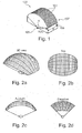
- Fig. 1 shows a conventional matrix array 100 of ultrasound transducer elements 103 arranged along a surface which is bent around an axis 105.
- the matrix array comprises a plurality of columns 107 and rows 109 of ultrasound transducer elements 103 arranged on a two-dimensional surface.
- the exemplary curved matrix array has a radius of curvature ROC of 11.5 mm, a field of view angle a of 130° in azimuth, and an aperture width w in elevation of 10 mm.
- the ultrasound transducer elements 103 are arranged with a phased-array pitch in elevation direction to support 90° steering.
- Figs. 2a,b,c and d show a perspective view, a top view, an azimuth view and an elevation view of the field of view obtainable with the curved matrix array shown in Fig. 1 .
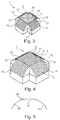
- Fig. 3 shows a perspective view of an ultrasound transducer matrix array 1 for an ultrasound probe, the matrix array 1 having a curved cross-shaped form and comprising a center region 11 interconnecting four branch regions 13.
- Each of the regions 11, 13 comprises a matrix array 5 of ultrasound transducers 3.
- the branch regions 13 extend from respective edges 15 of the center region 11.
- Each of the branch regions 13 is curved around an axis parallel to the respective edge 15 from which it extends.
- the center region 11 may have a complex curved surface which is curved in two directions.
- an ultrasound transducer matrix array 1' with a flat center region 11' as shown in Fig. 4 .
- the flat center region 11' may have a rectangular shape with four edges 15 from which curved branch regions 13 extend.
- the matrix array 5 of the flat center region 11' may comprise A columns 7 and B rows 9 of ultrasound transducer elements 3.
- the matrix arrays 5 of the branch regions 13 directly abut to one of the edges 15 of the center region 11' and each have the same width as the dimension of the edge 15 of the center region 11' from which they extend.
- the branch regions 13 may have A or B transducer elements 3 in a width direction.
- each of the branch regions may have a different length and/or a different radius of curvature; however, it may be advantageous to provide each of the branch regions with a same length and a same radius of curvature thereby achieving a symmetric arrangement.
- Fig. 5 shows a cross-section of the ultrasound transducer matrix array 1' shown in Fig. 4 .
- Two curved branch regions 13 extend from the flat center region 11' at edges 15.
- the field of view of ultrasound probe with a cross-shaped curved ultrasound transducer matrix array as shown in Fig. 4 may not be a complete spheroid; there may be gaps in the "corners" where neither of the orthogonal apertures can provide adequate image quality.
- the actual field of view of such cross-shaped ultrasound transducer may depend on both the curved surface provided by the basic geometry of the matrix arrays of ultrasound transducer elements, plus the available steering which may be dependent on the element pitch.
- Figs. 6a,b,c illustrate the resulting field of view in a perspective view, top view and azimuth/elevation view, respectively. This approach may provide coverage of about half of an ideal spheroidal field of view, with gaps in the "corners" which may be beyond the combined translation and steering of the composite array.
- Such a transducer may also provide improved image quality in the transverse plane through the center of the array, over a larger field of view, than would be possible with a single curved matrix array as for example shown in Fig. 1 .
- the image quality in the transverse plane may improve as well by providing for curved linear array operation in that direction, instead of relying only on steering.
- the curved matrix array shown in Fig. 1 may achieve a 90° field of view in elevation as shown in Fig. 2d only if it has phased-array pitch in elevation, whereas the cross-shaped array shown in Figs. 3 or 4 has a 130° field of view in elevation even if diced at a larger linear-array pitch.
- the improved image quality results from the larger available aperture in the elevation direction.
- such cross-shaped array as shown in Figs. 3 or 4 may have fewer ultrasound transducer elements and respective microchannels than a conventional curved matrix array as shown in Fig. 1 .
- the B rows must be diced on a phased array pitch.
- the cross-shaped array shown in Figs. 3 or 4 be symmetrical, where the dimensions of either major axis be the same as the array in Fig. 1 .
- the array be diced on linear array pitch in both directions; there will be 128 columns in the azimuth direction and 32 rows in the elevation direction for each of the crossed arrays.
- the crossed array may have more surface area, it has fewer array elements because it is diced at linear array pitch in both directions.
- Figs. 7a,b,c show a perspective view, a top view and an azimuth/elevation view, respectively, of a field of view for an ultrasound probe with an ultrasound transducer matrix array according to an embodiment of the present invention in which the entire array is diced to provide phased array pitch in elevation. This may provide about 90° of steering. In this case, the increased steering may provide for much more coverage of an ideal spheroidal field of view. As will be further described below with respect to Fig. 9 , it may not be necessary to dice the entire array at phased array pitch.
- matrix arrays having a 130° azimuth field of view as discussed further above with respect to the conventional curved matrix array show in Fig. 1 have been used for the various regions of the ultrasound probe.
- the result may be an improvement in field of view of somewhat less than 50% over the conventional single curved matrix array of Fig. 1 with 90° steering. If the azimuth field of view is increased above 130°, then the field of view improvement may increase beyond what is illustrated in Fig. 7 .
- the image quality in the transverse plane may improve as well by providing for curved linear array operation in that direction, instead of relying only on steering.
- Fig. 8 shows a cross sectional view of a matrix array 5 of ultrasound transducers 3.
- a plurality control circuits 37 have been integrated.
- Each of the control cirsuits 37 is connected via connections 33 to an associated layer arrangement 35 which may be activated to ultrasonic vibrations.
- the layer arrangement may comprise a piezoelectric layer together with one or more additional layers for improving acoustic impedance match, thereby forming an acoustic stack.
- the connections 33 have been established via flip-chip technology.
- the plurality of vibration layer arrangements 35 may be produced by first connecting an over-all layer arrangement to the substrate 31 and subsequently dicing it thereby separating the plurality of vibration layers arrangement 35.
- an over-all ultrasound transducer area of an ultrasound probe may be composed of a plurality of ultrasound transducer matrix array tiles 21, 23, 25.
- the over-all ultrasound transducer area may comprise at least three, but probably four or more, ASICs.
- a symmetrical over-all ultrasound transducer area is shown, but symmetry is not a requirement.
- Figs. 9 and 10 illustrate two embodiments in which two different ASIC designs A, B are used. The two designs may be most likely very similar and the system I/O 27 may be on the outer edges of the ASICs.
- the ASICs may be tiled prior to bonding to the acoustic stack.
- pre-bonded ASIC/acoustic stack sub-assemblies may be tiled.
- the pre-bonded sub-assemblies may be diced prior to tiling if either
- the over-all transducer area may be diced after tiling as described below.
- the tiling should be done on a substrate that either is or may be made flexible for later curving.
- the ASICs are tiled before bonding to the acoustic stack, then there may be two basic choices for probe configuration.
- the tiled ASIC sub-assembly may be bonded to a single large acoustic stack, but this might result in a significant amount of waste from unused corners (4/9 of the over-all area for a design with square symmetry).
- the probe may comprise either three or four pieces, in the same configuration as the ASIC as illustrated in Figs. 9 and 10 .
- the ultrasound unit including the over-all transducer area may be ready for dicing, assuming that the ASIC/probe sub-assemblies are not already diced when tiled.
- the array elements When diced after tiling, the array elements may be properly registered with respect to each other, although the underlying ASICs may be slightly misaligned.
- Fig. 12 shows an array geometry after dicing.
- the unit may then be ready for curving.
- the substrate may be made sufficiently bendable by using a bendable material.
- a rigid material may be made bendable by back-dicing.
- the tools and techniques for getting the suitable radius of curvature may be similar to those used for conventional one-dimensional transducer arrays.
- one approach may be to place the array face down into a curved tool that provides a specified radius of curvature, pushed into contact with the face of the tool, and bonded to a mechanical support structure behind the ASIC/array sub-assembly.
- Another approach may be to bond the array face up over a mechanical support structure.
- Either of these methods may be used for the conventional curved matrix transducer array shown in Fig. 1 . Similar techniques may be used for the cross-shaped matrix arrays, except that the tool and mechanical support may be more complex because there may be a flat center region in the middle and there may be two sets of curved branch regions extending therefrom.
- array manufacture may be completed using techniques similar to those used on conventional matrix arrays for ultrasound transducer probes.
- Fig. 13 illustrates a dicing pattern that provides for 90° steering in the elevation direction for each orthogonal sub-set of the over-all array. While dicing in each direction, the pitch may be halved the center region. This may result in elements that are ⁇ in azimuth and ⁇ /2 in elevation in the branch regions 13, and ⁇ /2 x ⁇ /2 in the flat center region 11. This approach may need different microchannel designs for each of the matrix arrays forming the center region 11 and the branch regions 13, but it may minimize the total number of microchannels.
Claims (14)
- Kreuzförmiges Ultraschallwandler-Matrixarray (1) für eine Ultraschallsonde, umfassend eine kreuzförmige Gesamtultraschallwandlerfläche, die Folgendes umfasst:eine Mittenregion (11) umfassend ein Matrixarray (5) von Ultraschallwandlerelementen (3), wobei die Mittenregion (11) vier Ränder (15) hat, undvier Zweigregionen (13), die jeweils ein Matrixarray (5) von Ultraschallwandlerelementen (3) umfassen, wobei sich jede Zweigregion (13) von einem der Ränder (15) der Mittenregion (11) aus erstreckt und wobei jede Zweigregion (13) um eine Achse herum gekrümmt ist, die parallel zum Rand (15) der Mittenregion (11) verläuft, von der sich die betreffende Zweigregion (13) aus erstreckt,dadurch gekennzeichnet, dass die Matrixarrays (5) von sowohl der Mittenregion (11) als auch der Zweigregionen (13) zweidimensionale Matrixarrays sind, die Wandlerelemente (3) umfassen, welche in einer Vielzahl von Reihen und einer Vielzahl von Spalten angeordnet sind.
- Ultraschallwandler-Matrixarray nach Anspruch 1, wobei die Mittenregion (11') flach ist.
- Ultraschallwandler-Matrixarray nach Anspruch 1 oder 2, umfassend eine rechteckige Mittenregion (11) mit einer Matrix aus A Reihen und B Spalten von Ultraschallwandlerelementen (3) und zwei Zweigregionen (13) jeweils mit einer Matrix aus A Reihen und C Spalten von Ultraschallwandlerelementen (3) und zwei Zweigregionen (13) jeweils mit einer Matrix aus D Reihen und B Spalten von Ultraschallwandlerelementen (3).
- Ultraschallwandler-Matrixarray nach einem der Ansprüche 1 bis 3, wobei mindestens ein Teil des Matrixarrays aus Wandlerelementen (3) der Mittenregion (11) und/oder der Zweigregionen (13) mit einem Phased-Array-Abstand angeordnet ist.
- Ultraschallwandler-Matrixarray nach einem der Ansprüche 1 bis 4, wobei das Matrixarray aus Wandlerelementen (3) der Mittenregion (11) mit einem Phased-Array-Abstand in beiden Hauptrichtungen angeordnet ist und wobei das Matrixarray von Wandlerelementen von jeder der Zweigregionen (13) mit einem Phased-Array-Abstand nur in den Hauptrichtungen parallel zu dem Rand (15) angeordnet ist, von dem aus sich die betreffende Zweigregion (13) erstreckt.
- Ultraschallwandler-Matrixarray nach einem der Ansprüche 1 bis 5, wobei Ultraschallwandlerelemente (3) mit einem biegbaren Substrat (31) versehen sind.
- Ultraschallwandler-Matrixarray nach einem der Ansprüche 1 bis 6, wobei jedes der Ultraschallwandlerelemente (3) eine zugehörige Steuerschaltung (37) hat.
- Ultraschallwandler-Matrixarray nach Anspruch 7, wobei die zugehörigen Steuerschaltungen (37) in einem gemeinsamen Substrat (31) integriert sind.
- Ultraschallwandler-Matrixarray nach Anspruch 8, wobei jedes der Ultraschallwandlerelemente (3) eine Schichtanordnung (35) umfasst, die für Ultraschallschwingungen aktiviert werden kann und mit einer in einem Substrat (31) enthaltenen Steuerschaltung (37) versehen ist, wobei die Schichtanordnung (35) mechanisch durch Flip-Chip-Technologie an dem Substrat (31) angebracht ist.
- Ultraschallwandler-Matrixarray nach einem der Ansprüche 1 bis 9, wobei die Gesamtultraschallwandlerfläche zusammengesetzt ist aus
einer Ultraschallwandler-Matrixarraykachel (21) umfassend eine Mittenregion (11) und zwei der Zweigregionen (13), die an gegenüberliegenden Rändern der Mittenregion (11) angeordnet sind, und
mindestens einer Ultraschallwandler-Matrixarraykachel (23) umfassend eine weitere Zweigregion (13). - Ultraschallwandler-Matrixarray nach einem der Ansprüche 1 bis 9, wobei die Gesamtultraschallwandlerfläche zusammengesetzt ist aus mindestens drei identischen Ultraschallwandler-Matrixarraykacheln (25).
- Verfahren zum Herstellen eines kreuzförmigen Ultraschallwandler-Matrixarrays für eine Ultraschallsonde (1), wobei das Verfahren Folgendes umfasst:- Bereitstellen einer kreuzförmigen Gesamtultraschallwandlerfläche, die Folgendes umfasst:eine Mittenregion (11) umfassend ein Matrixarray (5) von Ultraschallwandlerelementen (3), wobei die Mittenregion (11) vier Ränder (15) hat, undvier Zweigregionen (13), die jeweils ein Matrixarray (5) von Ultraschallwandlerelementen (3) umfassen, wobei sich jede Zweigregion (13) von einem der Ränder (15) der Mittenregion (11) aus erstreckt;- Anordnen jeder Zweigregion (13) in einer gekrümmten Konfiguration um eine Achse herum, die parallel zum Rand (15) der Mittenregion (11) verläuft, von der sich die betreffende Zweigregion (13) aus erstreckt,dadurch gekennzeichnet, dass die Matrixarrays (5) von sowohl der Mittenregion (11) als auch der Zweigregionen (13) zweidimensionale Matrixarrays sind, die Wandlerelemente (3) umfassen, welche in einer Vielzahl von Reihen und einer Vielzahl von Spalten angeordnet sind.
- Verfahren nach Anspruch 12, wobei die Mittenregion in einer flachen Konfiguration angeordnet ist.
- Verfahren nach Anspruch 12 oder 13, wobei jedes der Ultraschallwandlerelemente (3) eine Schichtanordnung (35) umfasst, die für Ultraschallschwingungen aktiviert werden kann und mit einer in einem Substrat (31) enthaltenen Steuerschaltung (37) versehen ist, wobei die Schichtanordnung (35) mechanisch durch Flip-Chip-Technologie an dem Substrat (31) angebracht ist.
Applications Claiming Priority (2)
| Application Number | Priority Date | Filing Date | Title |
|---|---|---|---|
| US23949709P | 2009-09-03 | 2009-09-03 | |
| PCT/IB2010/053858 WO2011027270A1 (en) | 2009-09-03 | 2010-08-27 | Ultrasound probe with large field of view and method for fabricating such ultrasound probe |
Publications (2)
| Publication Number | Publication Date |
|---|---|
| EP2473111A1 EP2473111A1 (de) | 2012-07-11 |
| EP2473111B1 true EP2473111B1 (de) | 2016-03-16 |
Family
ID=43242924
Family Applications (1)
| Application Number | Title | Priority Date | Filing Date |
|---|---|---|---|
| EP10762750.7A Not-in-force EP2473111B1 (de) | 2009-09-03 | 2010-08-27 | Ultraschallsonde mit breitem sichtfeld und verfahren zur herstellung einer derartigen ultraschallsonde |
Country Status (6)
| Country | Link |
|---|---|
| US (1) | US20120143063A1 (de) |
| EP (1) | EP2473111B1 (de) |
| JP (1) | JP5735512B2 (de) |
| CN (1) | CN102497820B (de) |
| RU (1) | RU2533336C2 (de) |
| WO (1) | WO2011027270A1 (de) |
Families Citing this family (27)
| Publication number | Priority date | Publication date | Assignee | Title |
|---|---|---|---|---|
| JP5691627B2 (ja) * | 2011-02-24 | 2015-04-01 | コニカミノルタ株式会社 | 超音波探触子及び超音波診断装置 |
| US20140225805A1 (en) * | 2011-03-15 | 2014-08-14 | Helen K. Pan | Conformal phased array antenna with integrated transceiver |
| WO2013168045A1 (en) * | 2012-05-09 | 2013-11-14 | Koninklijke Philips N.V. | Ultrasound transducer arrays with variable patch geometries |
| US9791565B2 (en) * | 2013-01-31 | 2017-10-17 | B-K Medical Aps | Multi-faced ultrasound transducer element |
| US9980704B2 (en) * | 2013-09-20 | 2018-05-29 | Transmural Biotech, S.L. | Non-invasive image analysis techniques for diagnosing diseases |
| WO2015115680A1 (ko) * | 2014-01-29 | 2015-08-06 | 알피니언메디칼시스템 주식회사 | 다종의 어레이가 형성된 트랜스듀서 및 그 제조방법, 다종의 어레이가 형성된 트랜스듀서를 포함하는 초음파 프로브 |
| US10557828B2 (en) | 2014-02-17 | 2020-02-11 | Westinghouse Electric Company Llc | Ultrasonic phased array transducer for the NDE inspection of the jet pump riser welds and welded attachments |
| US9955950B2 (en) * | 2014-07-30 | 2018-05-01 | General Electric Company | Systems and methods for steering multiple ultrasound beams |
| CN104359980B (zh) * | 2014-11-24 | 2017-01-04 | 清华大学 | 一种锯齿形柱状超声相控阵换能器 |
| KR102437475B1 (ko) * | 2014-12-05 | 2022-08-30 | 삼성메디슨 주식회사 | 초음파 프로브 |
| JP2017047180A (ja) * | 2015-09-04 | 2017-03-09 | キヤノン株式会社 | 探触子アレイ、および、該探触子アレイを備えた音響波測定装置。 |
| KR102438119B1 (ko) | 2015-10-16 | 2022-08-31 | 삼성전자주식회사 | 초음파 장치 및 초음파 촬영 방법 |
| CN105372326B (zh) * | 2015-10-20 | 2017-12-08 | 南京航空航天大学 | 一种基于Lamb波波数扫描的空间‑波数滤波器 |
| CN105372327B (zh) * | 2015-10-20 | 2017-12-05 | 南京航空航天大学 | 基于十字阵和波数扫描滤波器的在线损伤成像方法 |
| KR102591372B1 (ko) * | 2015-10-27 | 2023-10-20 | 삼성메디슨 주식회사 | 초음파 프로브 |
| KR102615034B1 (ko) * | 2016-02-22 | 2023-12-19 | 삼성메디슨 주식회사 | 초음파 프로브 |
| WO2017216365A1 (en) * | 2016-06-16 | 2017-12-21 | Koninklijke Philips N.V. | External microconvex-linear ultrasound probe |
| JP7025434B2 (ja) | 2017-01-19 | 2022-02-24 | コーニンクレッカ フィリップス エヌ ヴェ | 大面積超音波トランスデューサー組立体 |
| JP2018157458A (ja) * | 2017-03-21 | 2018-10-04 | セイコーエプソン株式会社 | 超音波アレイ、超音波センサー及び電子機器 |
| JP6896489B2 (ja) * | 2017-04-03 | 2021-06-30 | 株式会社東芝 | 超音波探傷装置、超音波探傷方法および製品の製造方法 |
| US20190053783A1 (en) * | 2017-08-15 | 2019-02-21 | Koninklijke Philips N.V. | Intracardiac therapeutic and diagnostic ultrasound device |
| JP6989416B2 (ja) * | 2017-08-25 | 2022-01-05 | 株式会社東芝 | リニアスキャン超音波探傷装置およびリニアスキャン超音波探傷方法 |
| US10416122B2 (en) * | 2017-10-31 | 2019-09-17 | Westinghouse Electric Company Llc | Ultrasonic phased array transducer apparatus for the nondestructive inspection of a component under test |
| KR102635043B1 (ko) * | 2017-11-29 | 2024-02-13 | 삼성메디슨 주식회사 | 초음파프로브 |
| KR102602493B1 (ko) * | 2018-01-15 | 2023-11-16 | 삼성메디슨 주식회사 | 초음파프로브 |
| RU2733704C2 (ru) * | 2018-12-24 | 2020-10-06 | Публичное акционерное общество "Газпром" | Акустическая антенна и способ ее работы |
| CN115079178A (zh) * | 2021-03-10 | 2022-09-20 | 苏州佳世达电通有限公司 | 水下超音波装置 |
Family Cites Families (23)
| Publication number | Priority date | Publication date | Assignee | Title |
|---|---|---|---|---|
| US3971962A (en) * | 1972-09-21 | 1976-07-27 | Stanford Research Institute | Linear transducer array for ultrasonic image conversion |
| US3881164A (en) * | 1973-09-13 | 1975-04-29 | Commw Of Australia | Cross array ultrasonic transducer |
| EP0090567B1 (de) | 1982-03-20 | 1988-07-27 | Fujitsu Limited | Ultraschallsonde zur Sektorabtastung |
| JPS58163347A (ja) * | 1982-03-20 | 1983-09-28 | 富士通株式会社 | 超音波三次元扇形走査探触子 |
| JPS62227327A (ja) * | 1986-03-28 | 1987-10-06 | 株式会社東芝 | 超音波プロ−ブ |
| EP0293803B1 (de) * | 1987-06-05 | 1996-12-18 | Hitachi, Ltd. | Ultraschallgerät mit fächerförmiger Abtastung für die Fehlererkennung |
| US4870867A (en) * | 1988-12-27 | 1989-10-03 | North American Philips Corp. | Crossed linear arrays for ultrasonic medical imaging |
| US5103129A (en) | 1990-07-26 | 1992-04-07 | Acoustic Imaging Technologies Corporation | Fixed origin biplane ultrasonic transducer |
| JPH05140A (ja) * | 1991-06-24 | 1993-01-08 | Matsushita Electric Ind Co Ltd | 超音波プローブおよび超音波診断装置 |
| JPH0533708U (ja) * | 1991-10-11 | 1993-05-07 | 横河メデイカルシステム株式会社 | 穿刺用超音波探触子 |
| RU2080592C1 (ru) * | 1994-02-21 | 1997-05-27 | Товарищество с ограниченной ответственностью "Фирма АКС" | Ультразвуковая антенная решетка в виде двухмерной матрицы |
| US5797845A (en) * | 1996-11-04 | 1998-08-25 | Barabash; Leonid S. | Ultrasound apparatus for three dimensional image reconstruction |
| US6102860A (en) * | 1998-12-24 | 2000-08-15 | Agilent Technologies, Inc. | Ultrasound transducer for three-dimensional imaging |
| JP4583561B2 (ja) * | 2000-08-08 | 2010-11-17 | ジーイー・メディカル・システムズ・グローバル・テクノロジー・カンパニー・エルエルシー | コンベックス型圧電素子アセンブリ及びコンベックス型圧電素子アセンブリの製造方法 |
| US6571444B2 (en) * | 2001-03-20 | 2003-06-03 | Vermon | Method of manufacturing an ultrasonic transducer |
| US6537219B2 (en) * | 2001-04-04 | 2003-03-25 | Koninklijke Philips Electronics N.V. | Static focus ultrasound apparatus and method |
| US6524254B2 (en) * | 2001-06-20 | 2003-02-25 | Bae Systems Information And Electronic Systems Integration, Inc. | Orthogonally reconfigurable integrated matrix acoustical array |
| WO2003000137A1 (en) * | 2001-06-20 | 2003-01-03 | Bae Systems Information And Electronic Systems Integration Inc. | Orthogonally reconfigurable integrated matrix acoustical array |
| US6915696B2 (en) * | 2003-02-27 | 2005-07-12 | Vermon | Intersecting ultrasonic transducer arrays |
| US7257051B2 (en) * | 2003-03-06 | 2007-08-14 | General Electric Company | Integrated interface electronics for reconfigurable sensor array |
| JP4969456B2 (ja) * | 2005-01-11 | 2012-07-04 | コーニンクレッカ フィリップス エレクトロニクス エヌ ヴィ | マイクロビームフォーマ及び医用超音波システム用再配布相互接続 |
| KR20080021635A (ko) * | 2005-06-07 | 2008-03-07 | 코닌클리케 필립스 일렉트로닉스 엔.브이. | 초음파 감지기 조립체를 위한 다수성분 받침 블록 |
| US7569975B2 (en) * | 2006-11-07 | 2009-08-04 | Olympus Ndt | Cable direct interconnection (CDI) method for phased array transducers |
-
2010
- 2010-08-27 RU RU2012112811/28A patent/RU2533336C2/ru not_active IP Right Cessation
- 2010-08-27 EP EP10762750.7A patent/EP2473111B1/de not_active Not-in-force
- 2010-08-27 WO PCT/IB2010/053858 patent/WO2011027270A1/en active Application Filing
- 2010-08-27 US US13/390,576 patent/US20120143063A1/en not_active Abandoned
- 2010-08-27 JP JP2012527424A patent/JP5735512B2/ja not_active Expired - Fee Related
- 2010-08-27 CN CN201080038815.9A patent/CN102497820B/zh not_active Expired - Fee Related
Also Published As
| Publication number | Publication date |
|---|---|
| JP2013504241A (ja) | 2013-02-04 |
| CN102497820B (zh) | 2015-10-07 |
| JP5735512B2 (ja) | 2015-06-17 |
| RU2012112811A (ru) | 2013-10-10 |
| RU2533336C2 (ru) | 2014-11-20 |
| EP2473111A1 (de) | 2012-07-11 |
| US20120143063A1 (en) | 2012-06-07 |
| CN102497820A (zh) | 2012-06-13 |
| WO2011027270A1 (en) | 2011-03-10 |
Similar Documents
| Publication | Publication Date | Title |
|---|---|---|
| EP2473111B1 (de) | Ultraschallsonde mit breitem sichtfeld und verfahren zur herstellung einer derartigen ultraschallsonde | |
| US6384516B1 (en) | Hex packed two dimensional ultrasonic transducer arrays | |
| EP2723506B1 (de) | Ultraschall wandleranordnung und verfahren zu deren herstellung | |
| US5651365A (en) | Phased array transducer design and method for manufacture thereof | |
| JP2651498B2 (ja) | 両面フエーズドアレイトランスデユーサ | |
| EP1912748B1 (de) | Gekrümmter zweidimensionaler array-wandler | |
| EP2243561B1 (de) | Array von elektroakustischen Wandlern und elektronische Sonde für dreidimensionale Bilder, die das Wandlerarray umfasst | |
| US7518290B2 (en) | Transducer array with non-uniform kerfs | |
| US4640291A (en) | Bi-plane phased array for ultrasound medical imaging | |
| US6759791B2 (en) | Multidimensional array and fabrication thereof | |
| JPH10304495A (ja) | 結合バッキングブロック及び複合変換器アレー | |
| JPH0744929B2 (ja) | 超音波結像装置 | |
| US7311667B2 (en) | Multiple pattern transducer array and method of use | |
| WO2014156976A1 (ja) | ユニモルフ型超音波探触子 | |
| JPH0723500A (ja) | 2次元アレイ超音波プローブ | |
| US20230415197A1 (en) | Planar Phased Ultrasound Transducer Array | |
| JP3944009B2 (ja) | 超音波振動子及びその製造方法 | |
| JP4338565B2 (ja) | 超音波探触子及び超音波探触子の製造方法 | |
| JP4963899B2 (ja) | 超音波探触子、超音波診断装置 | |
| JPH11205899A (ja) | 超音波探触子 | |
| EP3895812B1 (de) | Piezoelektrischer wandler mit gekrümmter form und verfahren zu seiner herstellung | |
| JPS62131700A (ja) | 超音波探触子及びその製造方法 | |
| CN114345673A (zh) | 超声换能器及其制作方法、以及超声换能系统 | |
| JPS63166400A (ja) | 超音波探触子 | |
| JP2005110171A (ja) | 超音波探触子 |
Legal Events
| Date | Code | Title | Description |
|---|---|---|---|
| PUAI | Public reference made under article 153(3) epc to a published international application that has entered the european phase |
Free format text: ORIGINAL CODE: 0009012 |
|
| 17P | Request for examination filed |
Effective date: 20120403 |
|
| AK | Designated contracting states |
Kind code of ref document: A1 Designated state(s): AL AT BE BG CH CY CZ DE DK EE ES FI FR GB GR HR HU IE IS IT LI LT LU LV MC MK MT NL NO PL PT RO SE SI SK SM TR |
|
| DAX | Request for extension of the european patent (deleted) | ||
| 17Q | First examination report despatched |
Effective date: 20130607 |
|
| RAP1 | Party data changed (applicant data changed or rights of an application transferred) |
Owner name: KONINKLIJKE PHILIPS N.V. |
|
| GRAP | Despatch of communication of intention to grant a patent |
Free format text: ORIGINAL CODE: EPIDOSNIGR1 |
|
| INTG | Intention to grant announced |
Effective date: 20150918 |
|
| GRAS | Grant fee paid |
Free format text: ORIGINAL CODE: EPIDOSNIGR3 |
|
| GRAA | (expected) grant |
Free format text: ORIGINAL CODE: 0009210 |
|
| AK | Designated contracting states |
Kind code of ref document: B1 Designated state(s): AL AT BE BG CH CY CZ DE DK EE ES FI FR GB GR HR HU IE IS IT LI LT LU LV MC MK MT NL NO PL PT RO SE SI SK SM TR |
|
| REG | Reference to a national code |
Ref country code: GB Ref legal event code: FG4D |
|
| REG | Reference to a national code |
Ref country code: CH Ref legal event code: EP |
|
| REG | Reference to a national code |
Ref country code: IE Ref legal event code: FG4D |
|
| REG | Reference to a national code |
Ref country code: AT Ref legal event code: REF Ref document number: 780470 Country of ref document: AT Kind code of ref document: T Effective date: 20160415 |
|
| REG | Reference to a national code |
Ref country code: DE Ref legal event code: R096 Ref document number: 602010031231 Country of ref document: DE |
|
| REG | Reference to a national code |
Ref country code: DE Ref legal event code: R084 Ref document number: 602010031231 Country of ref document: DE |
|
| REG | Reference to a national code |
Ref country code: NL Ref legal event code: MP Effective date: 20160316 |
|
| REG | Reference to a national code |
Ref country code: LT Ref legal event code: MG4D |
|
| PG25 | Lapsed in a contracting state [announced via postgrant information from national office to epo] |
Ref country code: NO Free format text: LAPSE BECAUSE OF FAILURE TO SUBMIT A TRANSLATION OF THE DESCRIPTION OR TO PAY THE FEE WITHIN THE PRESCRIBED TIME-LIMIT Effective date: 20160616 Ref country code: FI Free format text: LAPSE BECAUSE OF FAILURE TO SUBMIT A TRANSLATION OF THE DESCRIPTION OR TO PAY THE FEE WITHIN THE PRESCRIBED TIME-LIMIT Effective date: 20160316 Ref country code: GR Free format text: LAPSE BECAUSE OF FAILURE TO SUBMIT A TRANSLATION OF THE DESCRIPTION OR TO PAY THE FEE WITHIN THE PRESCRIBED TIME-LIMIT Effective date: 20160617 Ref country code: HR Free format text: LAPSE BECAUSE OF FAILURE TO SUBMIT A TRANSLATION OF THE DESCRIPTION OR TO PAY THE FEE WITHIN THE PRESCRIBED TIME-LIMIT Effective date: 20160316 |
|
| REG | Reference to a national code |
Ref country code: AT Ref legal event code: MK05 Ref document number: 780470 Country of ref document: AT Kind code of ref document: T Effective date: 20160316 |
|
| PG25 | Lapsed in a contracting state [announced via postgrant information from national office to epo] |
Ref country code: NL Free format text: LAPSE BECAUSE OF FAILURE TO SUBMIT A TRANSLATION OF THE DESCRIPTION OR TO PAY THE FEE WITHIN THE PRESCRIBED TIME-LIMIT Effective date: 20160316 Ref country code: LV Free format text: LAPSE BECAUSE OF FAILURE TO SUBMIT A TRANSLATION OF THE DESCRIPTION OR TO PAY THE FEE WITHIN THE PRESCRIBED TIME-LIMIT Effective date: 20160316 Ref country code: LT Free format text: LAPSE BECAUSE OF FAILURE TO SUBMIT A TRANSLATION OF THE DESCRIPTION OR TO PAY THE FEE WITHIN THE PRESCRIBED TIME-LIMIT Effective date: 20160316 Ref country code: SE Free format text: LAPSE BECAUSE OF FAILURE TO SUBMIT A TRANSLATION OF THE DESCRIPTION OR TO PAY THE FEE WITHIN THE PRESCRIBED TIME-LIMIT Effective date: 20160316 |
|
| PG25 | Lapsed in a contracting state [announced via postgrant information from national office to epo] |
Ref country code: EE Free format text: LAPSE BECAUSE OF FAILURE TO SUBMIT A TRANSLATION OF THE DESCRIPTION OR TO PAY THE FEE WITHIN THE PRESCRIBED TIME-LIMIT Effective date: 20160316 Ref country code: IS Free format text: LAPSE BECAUSE OF FAILURE TO SUBMIT A TRANSLATION OF THE DESCRIPTION OR TO PAY THE FEE WITHIN THE PRESCRIBED TIME-LIMIT Effective date: 20160716 Ref country code: PL Free format text: LAPSE BECAUSE OF FAILURE TO SUBMIT A TRANSLATION OF THE DESCRIPTION OR TO PAY THE FEE WITHIN THE PRESCRIBED TIME-LIMIT Effective date: 20160316 |
|
| PG25 | Lapsed in a contracting state [announced via postgrant information from national office to epo] |
Ref country code: RO Free format text: LAPSE BECAUSE OF FAILURE TO SUBMIT A TRANSLATION OF THE DESCRIPTION OR TO PAY THE FEE WITHIN THE PRESCRIBED TIME-LIMIT Effective date: 20160316 Ref country code: ES Free format text: LAPSE BECAUSE OF FAILURE TO SUBMIT A TRANSLATION OF THE DESCRIPTION OR TO PAY THE FEE WITHIN THE PRESCRIBED TIME-LIMIT Effective date: 20160316 Ref country code: CZ Free format text: LAPSE BECAUSE OF FAILURE TO SUBMIT A TRANSLATION OF THE DESCRIPTION OR TO PAY THE FEE WITHIN THE PRESCRIBED TIME-LIMIT Effective date: 20160316 Ref country code: AT Free format text: LAPSE BECAUSE OF FAILURE TO SUBMIT A TRANSLATION OF THE DESCRIPTION OR TO PAY THE FEE WITHIN THE PRESCRIBED TIME-LIMIT Effective date: 20160316 Ref country code: PT Free format text: LAPSE BECAUSE OF FAILURE TO SUBMIT A TRANSLATION OF THE DESCRIPTION OR TO PAY THE FEE WITHIN THE PRESCRIBED TIME-LIMIT Effective date: 20160718 Ref country code: SK Free format text: LAPSE BECAUSE OF FAILURE TO SUBMIT A TRANSLATION OF THE DESCRIPTION OR TO PAY THE FEE WITHIN THE PRESCRIBED TIME-LIMIT Effective date: 20160316 Ref country code: SM Free format text: LAPSE BECAUSE OF FAILURE TO SUBMIT A TRANSLATION OF THE DESCRIPTION OR TO PAY THE FEE WITHIN THE PRESCRIBED TIME-LIMIT Effective date: 20160316 |
|
| REG | Reference to a national code |
Ref country code: DE Ref legal event code: R097 Ref document number: 602010031231 Country of ref document: DE |
|
| PG25 | Lapsed in a contracting state [announced via postgrant information from national office to epo] |
Ref country code: BE Free format text: LAPSE BECAUSE OF FAILURE TO SUBMIT A TRANSLATION OF THE DESCRIPTION OR TO PAY THE FEE WITHIN THE PRESCRIBED TIME-LIMIT Effective date: 20160316 Ref country code: IT Free format text: LAPSE BECAUSE OF FAILURE TO SUBMIT A TRANSLATION OF THE DESCRIPTION OR TO PAY THE FEE WITHIN THE PRESCRIBED TIME-LIMIT Effective date: 20160316 |
|
| PLBE | No opposition filed within time limit |
Free format text: ORIGINAL CODE: 0009261 |
|
| STAA | Information on the status of an ep patent application or granted ep patent |
Free format text: STATUS: NO OPPOSITION FILED WITHIN TIME LIMIT |
|
| PG25 | Lapsed in a contracting state [announced via postgrant information from national office to epo] |
Ref country code: DK Free format text: LAPSE BECAUSE OF FAILURE TO SUBMIT A TRANSLATION OF THE DESCRIPTION OR TO PAY THE FEE WITHIN THE PRESCRIBED TIME-LIMIT Effective date: 20160316 |
|
| 26N | No opposition filed |
Effective date: 20161219 |
|
| PG25 | Lapsed in a contracting state [announced via postgrant information from national office to epo] |
Ref country code: BG Free format text: LAPSE BECAUSE OF FAILURE TO SUBMIT A TRANSLATION OF THE DESCRIPTION OR TO PAY THE FEE WITHIN THE PRESCRIBED TIME-LIMIT Effective date: 20160616 |
|
| PG25 | Lapsed in a contracting state [announced via postgrant information from national office to epo] |
Ref country code: MC Free format text: LAPSE BECAUSE OF FAILURE TO SUBMIT A TRANSLATION OF THE DESCRIPTION OR TO PAY THE FEE WITHIN THE PRESCRIBED TIME-LIMIT Effective date: 20160316 |
|
| REG | Reference to a national code |
Ref country code: CH Ref legal event code: PL |
|
| GBPC | Gb: european patent ceased through non-payment of renewal fee |
Effective date: 20160827 |
|
| PG25 | Lapsed in a contracting state [announced via postgrant information from national office to epo] |
Ref country code: LI Free format text: LAPSE BECAUSE OF NON-PAYMENT OF DUE FEES Effective date: 20160831 Ref country code: CH Free format text: LAPSE BECAUSE OF NON-PAYMENT OF DUE FEES Effective date: 20160831 |
|
| REG | Reference to a national code |
Ref country code: FR Ref legal event code: ST Effective date: 20170428 |
|
| PG25 | Lapsed in a contracting state [announced via postgrant information from national office to epo] |
Ref country code: SI Free format text: LAPSE BECAUSE OF FAILURE TO SUBMIT A TRANSLATION OF THE DESCRIPTION OR TO PAY THE FEE WITHIN THE PRESCRIBED TIME-LIMIT Effective date: 20160316 |
|
| REG | Reference to a national code |
Ref country code: IE Ref legal event code: MM4A |
|
| PG25 | Lapsed in a contracting state [announced via postgrant information from national office to epo] |
Ref country code: FR Free format text: LAPSE BECAUSE OF NON-PAYMENT OF DUE FEES Effective date: 20160831 Ref country code: IE Free format text: LAPSE BECAUSE OF NON-PAYMENT OF DUE FEES Effective date: 20160827 Ref country code: GB Free format text: LAPSE BECAUSE OF NON-PAYMENT OF DUE FEES Effective date: 20160827 |
|
| PG25 | Lapsed in a contracting state [announced via postgrant information from national office to epo] |
Ref country code: LU Free format text: LAPSE BECAUSE OF NON-PAYMENT OF DUE FEES Effective date: 20160827 |
|
| PG25 | Lapsed in a contracting state [announced via postgrant information from national office to epo] |
Ref country code: CY Free format text: LAPSE BECAUSE OF FAILURE TO SUBMIT A TRANSLATION OF THE DESCRIPTION OR TO PAY THE FEE WITHIN THE PRESCRIBED TIME-LIMIT Effective date: 20160316 Ref country code: HU Free format text: LAPSE BECAUSE OF FAILURE TO SUBMIT A TRANSLATION OF THE DESCRIPTION OR TO PAY THE FEE WITHIN THE PRESCRIBED TIME-LIMIT; INVALID AB INITIO Effective date: 20100827 |
|
| PG25 | Lapsed in a contracting state [announced via postgrant information from national office to epo] |
Ref country code: TR Free format text: LAPSE BECAUSE OF FAILURE TO SUBMIT A TRANSLATION OF THE DESCRIPTION OR TO PAY THE FEE WITHIN THE PRESCRIBED TIME-LIMIT Effective date: 20160316 Ref country code: MK Free format text: LAPSE BECAUSE OF FAILURE TO SUBMIT A TRANSLATION OF THE DESCRIPTION OR TO PAY THE FEE WITHIN THE PRESCRIBED TIME-LIMIT Effective date: 20160316 Ref country code: MT Free format text: LAPSE BECAUSE OF NON-PAYMENT OF DUE FEES Effective date: 20160831 |
|
| PG25 | Lapsed in a contracting state [announced via postgrant information from national office to epo] |
Ref country code: AL Free format text: LAPSE BECAUSE OF FAILURE TO SUBMIT A TRANSLATION OF THE DESCRIPTION OR TO PAY THE FEE WITHIN THE PRESCRIBED TIME-LIMIT Effective date: 20160316 |
|
| PGFP | Annual fee paid to national office [announced via postgrant information from national office to epo] |
Ref country code: DE Payment date: 20191031 Year of fee payment: 10 |
|
| REG | Reference to a national code |
Ref country code: DE Ref legal event code: R119 Ref document number: 602010031231 Country of ref document: DE |
|
| PG25 | Lapsed in a contracting state [announced via postgrant information from national office to epo] |
Ref country code: DE Free format text: LAPSE BECAUSE OF NON-PAYMENT OF DUE FEES Effective date: 20210302 |