EP2472547A2 - Locking device for use with a circuit breaker and method of assembly - Google Patents
Locking device for use with a circuit breaker and method of assembly Download PDFInfo
- Publication number
- EP2472547A2 EP2472547A2 EP11194081A EP11194081A EP2472547A2 EP 2472547 A2 EP2472547 A2 EP 2472547A2 EP 11194081 A EP11194081 A EP 11194081A EP 11194081 A EP11194081 A EP 11194081A EP 2472547 A2 EP2472547 A2 EP 2472547A2
- Authority
- EP
- European Patent Office
- Prior art keywords
- locking
- locking device
- circuit breaker
- arm
- contact arm
- Prior art date
- Legal status (The legal status is an assumption and is not a legal conclusion. Google has not performed a legal analysis and makes no representation as to the accuracy of the status listed.)
- Granted
Links
Images





Classifications
-
- H—ELECTRICITY
- H01—ELECTRIC ELEMENTS
- H01H—ELECTRIC SWITCHES; RELAYS; SELECTORS; EMERGENCY PROTECTIVE DEVICES
- H01H71/00—Details of the protective switches or relays covered by groups H01H73/00 - H01H83/00
- H01H71/10—Operating or release mechanisms
- H01H71/12—Automatic release mechanisms with or without manual release
- H01H71/128—Manual release or trip mechanisms, e.g. for test purposes
-
- H—ELECTRICITY
- H01—ELECTRIC ELEMENTS
- H01H—ELECTRIC SWITCHES; RELAYS; SELECTORS; EMERGENCY PROTECTIVE DEVICES
- H01H71/00—Details of the protective switches or relays covered by groups H01H73/00 - H01H83/00
- H01H71/10—Operating or release mechanisms
- H01H71/50—Manual reset mechanisms which may be also used for manual release
- H01H71/505—Latching devices between operating and release mechanism
-
- H—ELECTRICITY
- H01—ELECTRIC ELEMENTS
- H01H—ELECTRIC SWITCHES; RELAYS; SELECTORS; EMERGENCY PROTECTIVE DEVICES
- H01H71/00—Details of the protective switches or relays covered by groups H01H73/00 - H01H83/00
- H01H71/10—Operating or release mechanisms
- H01H71/66—Power reset mechanisms
- H01H71/68—Power reset mechanisms actuated by electromagnet
-
- H—ELECTRICITY
- H01—ELECTRIC ELEMENTS
- H01H—ELECTRIC SWITCHES; RELAYS; SELECTORS; EMERGENCY PROTECTIVE DEVICES
- H01H9/00—Details of switching devices, not covered by groups H01H1/00 - H01H7/00
- H01H9/20—Interlocking, locking, or latching mechanisms
-
- Y—GENERAL TAGGING OF NEW TECHNOLOGICAL DEVELOPMENTS; GENERAL TAGGING OF CROSS-SECTIONAL TECHNOLOGIES SPANNING OVER SEVERAL SECTIONS OF THE IPC; TECHNICAL SUBJECTS COVERED BY FORMER USPC CROSS-REFERENCE ART COLLECTIONS [XRACs] AND DIGESTS
- Y10—TECHNICAL SUBJECTS COVERED BY FORMER USPC
- Y10T—TECHNICAL SUBJECTS COVERED BY FORMER US CLASSIFICATION
- Y10T29/00—Metal working
- Y10T29/49—Method of mechanical manufacture
- Y10T29/49002—Electrical device making
- Y10T29/49105—Switch making
Definitions
- circuit breakers relate generally to circuit breakers and, more particularly, to devices that enable locking of circuit breakers in a tripped position and enable tripping of circuit breakers.
- At least some known circuit breakers include an interlock and an auxiliary latch, wherein the interlock prevents the auxiliary latch from re-engaging after the circuit breaker has tripped due to detection of a tripping criteria, such as an overcurrent detection. For example, the interlock prevents the auxiliary latch from re-engaging until the circuit breaker is manually reset.
- at least some known circuit breakers include a handle that enables a user, such as service personnel, to manually separate primary electrical contacts within the circuit breaker. The handle is coupled to secondary electrical contacts that provide power to the handle such that, when a preselected condition is detected and when the handle is in an "on" position, the primary electrical contacts are reconnected to enable current to flow through the circuit breaker.
- such known circuit breakers do not enable a circuit breaker to be manually tripped and locked in the tripped or open position using an externally-located arm or lever.
- a circuit protection device in one aspect, includes a circuit breaker having a first contact arm and a second contact arm, wherein the second contact arm is configured to move with respect to the first contact arm between a first position and a second position.
- the circuit protection device also includes a locking device coupled to the circuit breaker, wherein the locking device is configured to move the second contact arm from the first position to the second position and/or lock the second contact arm in the second position.
- a locking device for use with a circuit breaker that includes at least one movable contact arm configured to move between a first position and a second position.
- the locking device includes a housing comprising an opening extending therethrough, and a rotor configured to be coupled to the housing and to the circuit breaker, wherein the rotor configured to rotate about an axis.
- the locking device also includes a locking arm extending through the opening and coupled to the rotor such that an actuating force on the locking arm causes the at least one contact arm to be locked in the second position and/or move from the first position to the second position.
- a method of assembling a circuit protection device includes a circuit breaker having a first contact arm and a second contact arm that is configured to move with respect to the first contact arm between a first position and a second position.
- the method includes coupling a locking device to the circuit breaker, wherein the locking device is configured to cause the second contact arm to move from the first position to the second position and/or lock the second contact arm in the second position.
- Fig. 1 is a side view of an exemplary circuit breaker in an open or tripped state.
- Fig. 2 is a side view of the circuit breaker shown in Fig. 1 in a closed or active state.
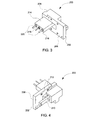
- Figs. 3 and 4 are perspective views of a locking device that may be used with the circuit breaker shown in Figs. 1 and 2 .
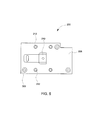
- Fig. 5 is a front view of the locking device shown in Figs. 3 and 4 .
- Fig. 6 is another perspective view of the locking device shown in Figs. 3 and 4 and the circuit breaker shown in Figs. 1 and 2 .
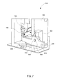
- Fig. 7 is a view of an alternative locking device for use with the circuit breaker shown in Figs. 1 and 2 .
- Fig. 8 is a view of another alternative locking device for use with the circuit breaker shown in Figs. 1 and 2 .
- Fig. 9 is a cross-sectional view of the locking device shown in Fig. 8 .
- Exemplary embodiments of apparatus and methods for use with circuit breakers are described herein. These embodiments provide a mechanical device that is accessible from outside of a circuit breaker. Moreover, these embodiments facilitate preventing the circuit breaker contacts from touching each other and facilitate causing the circuit breaker contacts to separate from a closed position. More specifically, the circuit breaker contacts can be locked in an open position or a trip of the circuit breaker can be initiated, wherein the contacts are moved from a closed position to the open position. When the contacts are locked in an open position, a contact arm can begin a closing operation but is prevented from completing the closing operation. For example, the contact arm begins a movement from an open position to a closed position but is prevented from completing the movement and returns to the open position. These locking and tripping operations provide greater safety to service personnel during maintenance operations. Moreover, the embodiments described herein can be used with an automated actuating device that causes the circuit breaker to lock or to initiate a trip based on a mechanical signal.
- circuit protection device 100 includes a circuit breaker 102 having a first contact arm 104 that is coupled, such as fixedly coupled, to a frame 106 of circuit breaker 102.
- First contact arm 104 includes a first end 108 and an opposite second end 110.
- First end 108 includes a first electrically conductive contact 112.
- Circuit breaker 102 also includes a second contact arm 114 that is movable with respect to first contact arm 104 between a first position and a second position.
- second contact arm 114 is in the first position when circuit breaker 102 is in the closed state and is in the second position when circuit breaker 102 is in the open state.
- Second contact arm 114 includes a first end 116 and an opposite second end 118.
- First end 116 includes a second electrically conductive contact 120 that conducts electrical energy to first conductive contact 112.
- second contact arm 114 rotates about a first pivot point 122 such that first and second conductive contacts 112 and 120 contact each other in the first position and are spaced apart from each other in the second position.
- Second contact arm 114 also includes a latch bolt 124 that facilitates locking second contact arm 114 in the second position as described below.
- circuit breaker 102 also includes a compression element 126, such as a spring.
- Compression element 126 includes a first end 128 and an opposite second end 130.
- First end 128 is coupled to frame 106.
- Second end 130 is coupled to second contact arm 114 to facilitate moving second contact arm 114 between the first and second positions.
- a first latch 132 is coupled to frame 106 and to second contact arm 114.
- First latch 132 is moveable between a latched position and an unlatched position about a second pivot point 134.
- Circuit breaker 102 also includes a second latch 136 that, in an exemplary embodiment, is coupled to first latch 132 at a third pivot point 138.
- Second latch 136 rotates about third pivot point 138 to engage with and disengage from latch bolt 124 as described below. More specifically, first latch 132 is coupled to second contact arm 114 at third pivot point 138 by means of second latch 136 and latch bolt 124.
- circuit breaker 102 includes a solenoid 140 that is coupled to frame 106.
- Solenoid 140 includes a linkage 142 that is coupled to first latch 132.
- Linkage 142 causes first latch 132 to rotate about second pivot point 134 to the latched and unlatched positions.
- Circuit breaker 102 also includes a lever 144 that is coupled to frame 106.
- Lever 144 includes a first end 146 and a second end 148.
- a tripping block 150 is provided at second end 148 to enable second latch 136 to disengage with latch bolt 124.
- lever 144 rotates about a fourth pivot point 152 such that tripping block 150 enables second latch 136 to engage and disengage with latch bolt 124.
- Circuit breaker 102 also includes an overcurrent trip unit 154 coupled to frame 106.
- Trip unit 154 includes a current sensor (not shown) that measures current through a conductor.
- Trip unit 154 determines whether the measured current is higher than a preselected threshold.
- trip unit 154 detects an overcurrent, trip unit 154 causes a tripping rod 156 to engage with lever first end 146.
- the tripping rod induces a downward force on first end 146, which causes lever 144 to rotate about fourth pivot point 152.
- the rotation of lever 144 causes tripping block 150 to cause second latch 136 to disengage from latch bolt 124. This enables compression element 126 to cause second contact arm 114 to move away from first contact arm 104.
- circuit breaker 102 also includes an impulse trip device 158 that includes an impulse coil 160 and a projection 162 that is movably coupled to impulse coil 160.
- Impulse coil 160 receives a signal from, for example, an external controller or other electronic source, and causes projection 162 to move upward along a pin or rod to induce an upward force on lever second end 148. More specifically, projection 162 causes lever 144 to rotate about fourth pivot point 152, which causes second latch 136 to disengage from latch bolt 124. This enables compression element 126 to cause second contact arm 114 to move away from first contact arm 104.
- first contact arm 104 and second contact arm 114 are maintained in the open state by a force generated by compression element 126.
- first latch 132 is maintained in an unlatched position by solenoid 140.
- solenoid 140 induces a force on first latch 132 via linkage 142 to maintain first latch 132 in the unlatched position when first and second contact arms 104 and 114 are in the open state.
- second latch 136 is engaged with latch bolt 124.
- lever 144 is maintained in a neutral state that enables second latch 136 to remain engaged with latch bolt 124.
- solenoid 140 causes linkage 142 to move linearly toward solenoid 140.
- the linear motion of linkage 142 causes first latch 132 to rotate about second pivot point 134 from an unlatch position to a latched position.
- the rotation of first latch 132 causes second contact arm 114 to move towards first contact arm 104 until first and second conductive contacts 112 and 120 meet.
- Second latch 136 remains engaged with latch bolt 124, and lever 144 remains in the neutral state.
- first contact arm 104 and second contact arm 114 are maintained in the closed state by the engagement of second latch 136 with latch bolt 124. Moreover, a contact force between first and second conductive contacts 112 and 120 is maintained by compression element 126. When first contact arm 104 and second contact arm 114 are in the closed state, lever 144 remains in the neutral state.
- first and second contact arms 104 and 114 In order to reposition first and second contact arms 104 and 114 into the open state, such as when the current sensor determines that the measured current is greater than the threshold current, tripping rod 156 of trip unit 154 moves downward and induces a force on lever first end 146, which causes lever 144 to rotate about fourth pivot point 152. Rotation of lever 144 causes tripping block 150 to induce a force on second latch 136, thereby causing second latch 136 to disengage from latch bolt 124. When second latch 136 and latch bolt 124 have disengaged, compression element 126 causes second contact arm 114 to move away from first contact arm 104.
- impulse coil 160 causes projection 162 to move upward along a pin or rod to induce an upward force on lever second end 148. More specifically, projection 160 causes lever 144 to rotate about fourth pivot point 152, which causes second latch 136 to disengage from latch bolt 124. This enables compression element 126 to cause second contact arm 114 to move away from first contact arm 104.
- Figs. 3-6 are views of an exemplary locking device 200 for use with circuit breaker 102.
- Figs. 3 and 4 are perspective views of locking device 200 of circuit protection device 100
- Fig. 5 is a front view of locking device 200
- Fig. 6 is a perspective view of locking device 200 and circuit breaker 102.
- locking device 200 includes a main body 202 having an inner surface 204 and an opposite outer surface 206.
- a housing 208 is positioned along a portion of outer surface 206.
- main body 202 and housing 208 are unitary or integrally formed.
- main body 202 and housing 208 are coupled together.
- a locking arm 210 extends out of housing 208 to receive an input from a user or from an automatic actuating device (not shown).
- the actuating device is coupled to main body 202 via a plurality of mounting apertures 212.
- a plurality of pins or other fastening mechanisms of the actuating device are inserted into respective mounting apertures 212 to facilitate coupling the actuating device to main body 202.
- a rotor 214 extends from housing 208 through main body 202.
- Rotor 214 includes locking arm 210 at one end.
- a plurality of pins extends from an end surface 216 of rotor 214, including an axle pin 218 and two coupling pins 220.
- lever 144 includes a plurality of openings each sized to receive a respective pin.
- lever 144 includes two first openings 222 that are each sized to receive a respective coupling pin 220 therein, and a second opening 224 that is sized to receive axle pin 218 therein.
- Rotor 214 rotates about axle pin 218, thereby causing lever 144 to rotate about fourth pivot point 152 (shown in Figs. 1 and 2 ), based on the input received via locking arm 210.
- Coupling pins 220 facilitate securing locking device 200 to circuit breaker 100.
- an actuating force is received via locking arm 210.
- the actuating force is an upward force induced on locking arm 210 by service personnel or by an actuating device.
- the actuating force causes locking arm 210 to rotate, such as rotating clockwise, to a trip position.
- the rotation of locking arm 210 translates to rotor 214, which also rotates.
- the rotation of rotor 214 similarly causes lever 144 to rotate about fourth pivot point 152, which is substantially aligned with axle pin 218.
- lever 144 causes tripping block 150 to contact second latch 136 (shown in Figs. 1 and 2 ).
- tripping block 150 induces an upward force on second latch 136 that causes second latch 136 to disengage from latch bolt 124 (shown in Figs. 1 and 2 ).
- compression element 126 shown in Figs. 1 and 2
- second contact arm 114 moves away from first contact arm 104. This motion causes first and second conductive contacts 112 and 120 (both shown in Figs. 1 and 2 ) to separate, thereby breaking the electrical connection between them such that current can no longer flow through circuit breaker 102.
- locking device 200 also facilitates locking circuit breaker 102 in the open state, wherein first and second contact arms 104 and 114 are separated.
- locking arm 210 is maintained in the trip position. Maintaining locking arm 210 in the trip position also causes lever 144 to remain in its rotated position, which disengages, or prevents engagement of, second latch 136 and latch bolt 124 during a closing operation in which second contact arm 114 moves from the second position towards the first position. For example, if solenoid 140 (shown in Figs.
- tripping block 150 causes second latch 136 to disengage from latch bolt 124.
- an edge of second latch 136 makes contact with an edge of tripping block 150, which causes second latch 136 to remain disengaged from latch bolt 124. Accordingly, compression element 126 continues to hold second contact arm 114 in the second position.
- Fig. 7 is a view of an alternative locking device 300 for use with circuit breaker 102 of circuit protection device 100.
- locking device 300 includes a housing 302 and a locking arm 304 that extends through housing 302 into circuit breaker 102.
- Locking arm 304 includes a first end 306 and an opposite second end 308.
- First end 306 extends outward from housing 302 away from circuit breaker 102 to receive an actuating force from service personnel or an actuating device.
- Second end 308 partially extends into circuit breaker 102 from housing 302 along a first axis and contacts tripping block 150.
- a retracting spring (not shown) is provided within housing 302 to facilitate returning arm 304 to its original position after receiving the actuating force.
- locking arm 304 is coupled to housing 302 by a pin 310 that extends through a first opening 312 within locking arm 304.
- Locking arm 304 includes a second opening 314 that enables the actuating device to be coupled to locking device 300.
- Locking device 300 enables service personnel or the actuating device to cause circuit breaker 102 to trip, or move first and second contact arms 104 and 114 (shown in Figs. 1 and 2 ) from the closed position to the open position. Moreover, locking device 300 enables service personnel or the actuating device to lock first and second contact arms 104 and 114 in the open position.
- the actuating force is a downward force on first end 306, which causes locking arm 304 to rotate about pin 310.
- the actuating force causes locking arm 304 to rotate about a second axis that is substantially perpendicular to the first axis.
- the rotation of arm 304 causes second end 308 to induce an upward force on tripping block 150.
- the upward force causes tripping block 150 to induce an upward force on second latch 136 that causes second latch 136 to disengage with latch bolt 124 (shown in Figs. 1 and 2 ).
- latch bolt 124 shown in Figs. 1 and 2
- compression element 126 causes second contact arm 114 to move away from first contact arm 104. This motion causes first and second conductive contacts 112 and 120 (both shown in Figs. 1 and 2 ) to separate, thereby breaking the electrical connection between them such that current can no longer flow through circuit breaker 102.
- Figs. 8 and 9 are views of another alternative locking device 400 for use with circuit breaker 102 of circuit protection device 100.
- locking device 400 includes a shaft 402 that extends through circuit breaker 102.
- Shaft 402 includes a first end 404 and an opposite second end 406.
- An arm 408 is coupled to shaft 402 at each end 404 and 406. Providing multiple arms 408 facilitates orienting circuit breaker 102 in multiple operating environments.
- Fig. 9 is a cross-sectional view of circuit breaker 102 and locking device 400.
- locking device 400 also includes a trip lever 410 that is coupled to shaft 402.
- circuit protection devices locking devices, and methods of assembling a circuit protection device having a circuit breaker and a locking device are described above in detail.
- the systems, methods, and apparatus are not limited to the specific embodiments described herein but, rather, operations of the methods and/or components of the apparatus and/or systems may be utilized independently and separately from other operations and/or components described herein. Further, the described operations and/or components may also be defined in, or used in combination with, other systems, methods, and/or apparatus, and are not limited to practice with only the systems, methods, and storage media as described herein.
Landscapes
- Breakers (AREA)
Abstract
Description
- The embodiments described herein relate generally to circuit breakers and, more particularly, to devices that enable locking of circuit breakers in a tripped position and enable tripping of circuit breakers.
- At least some known circuit breakers include an interlock and an auxiliary latch, wherein the interlock prevents the auxiliary latch from re-engaging after the circuit breaker has tripped due to detection of a tripping criteria, such as an overcurrent detection. For example, the interlock prevents the auxiliary latch from re-engaging until the circuit breaker is manually reset. Moreover, at least some known circuit breakers include a handle that enables a user, such as service personnel, to manually separate primary electrical contacts within the circuit breaker. The handle is coupled to secondary electrical contacts that provide power to the handle such that, when a preselected condition is detected and when the handle is in an "on" position, the primary electrical contacts are reconnected to enable current to flow through the circuit breaker. However, such known circuit breakers do not enable a circuit breaker to be manually tripped and locked in the tripped or open position using an externally-located arm or lever.
- In one aspect, a circuit protection device includes a circuit breaker having a first contact arm and a second contact arm, wherein the second contact arm is configured to move with respect to the first contact arm between a first position and a second position. The circuit protection device also includes a locking device coupled to the circuit breaker, wherein the locking device is configured to move the second contact arm from the first position to the second position and/or lock the second contact arm in the second position.
- In another aspect, a locking device is provided for use with a circuit breaker that includes at least one movable contact arm configured to move between a first position and a second position. The locking device includes a housing comprising an opening extending therethrough, and a rotor configured to be coupled to the housing and to the circuit breaker, wherein the rotor configured to rotate about an axis. The locking device also includes a locking arm extending through the opening and coupled to the rotor such that an actuating force on the locking arm causes the at least one contact arm to be locked in the second position and/or move from the first position to the second position.
- In another aspect, a method of assembling a circuit protection device is provided, wherein the circuit protection device includes a circuit breaker having a first contact arm and a second contact arm that is configured to move with respect to the first contact arm between a first position and a second position. The method includes coupling a locking device to the circuit breaker, wherein the locking device is configured to cause the second contact arm to move from the first position to the second position and/or lock the second contact arm in the second position.
-
Fig. 1 is a side view of an exemplary circuit breaker in an open or tripped state. -
Fig. 2 is a side view of the circuit breaker shown inFig. 1 in a closed or active state. -
Figs. 3 and 4 are perspective views of a locking device that may be used with the circuit breaker shown inFigs. 1 and2 . -
Fig. 5 is a front view of the locking device shown inFigs. 3 and 4 . -
Fig. 6 is another perspective view of the locking device shown inFigs. 3 and 4 and the circuit breaker shown inFigs. 1 and2 . -
Fig. 7 is a view of an alternative locking device for use with the circuit breaker shown inFigs. 1 and2 . -
Fig. 8 is a view of another alternative locking device for use with the circuit breaker shown inFigs. 1 and2 . -
Fig. 9 is a cross-sectional view of the locking device shown inFig. 8 . - Exemplary embodiments of apparatus and methods for use with circuit breakers are described herein. These embodiments provide a mechanical device that is accessible from outside of a circuit breaker. Moreover, these embodiments facilitate preventing the circuit breaker contacts from touching each other and facilitate causing the circuit breaker contacts to separate from a closed position. More specifically, the circuit breaker contacts can be locked in an open position or a trip of the circuit breaker can be initiated, wherein the contacts are moved from a closed position to the open position. When the contacts are locked in an open position, a contact arm can begin a closing operation but is prevented from completing the closing operation. For example, the contact arm begins a movement from an open position to a closed position but is prevented from completing the movement and returns to the open position. These locking and tripping operations provide greater safety to service personnel during maintenance operations. Moreover, the embodiments described herein can be used with an automated actuating device that causes the circuit breaker to lock or to initiate a trip based on a mechanical signal.
-
Fig. 1 is a side view of an exemplarycircuit protection device 100 in an open or tripped state, andFig. 2 is a side view ofcircuit protection device 100 in a closed or active state. In an exemplary embodiment,circuit protection device 100 includes acircuit breaker 102 having afirst contact arm 104 that is coupled, such as fixedly coupled, to aframe 106 ofcircuit breaker 102.First contact arm 104 includes afirst end 108 and an opposite second end 110.First end 108 includes a first electricallyconductive contact 112.Circuit breaker 102 also includes asecond contact arm 114 that is movable with respect tofirst contact arm 104 between a first position and a second position. For example,second contact arm 114 is in the first position whencircuit breaker 102 is in the closed state and is in the second position whencircuit breaker 102 is in the open state.Second contact arm 114 includes afirst end 116 and an oppositesecond end 118.First end 116 includes a second electricallyconductive contact 120 that conducts electrical energy to firstconductive contact 112. Moreover,second contact arm 114 rotates about afirst pivot point 122 such that first and secondconductive contacts Second contact arm 114 also includes alatch bolt 124 that facilitates lockingsecond contact arm 114 in the second position as described below. - In an exemplary embodiment,
circuit breaker 102 also includes acompression element 126, such as a spring.Compression element 126 includes a first end 128 and an opposite second end 130. First end 128 is coupled toframe 106. Second end 130 is coupled tosecond contact arm 114 to facilitate movingsecond contact arm 114 between the first and second positions. Moreover, afirst latch 132 is coupled toframe 106 and tosecond contact arm 114.First latch 132 is moveable between a latched position and an unlatched position about asecond pivot point 134.Circuit breaker 102 also includes asecond latch 136 that, in an exemplary embodiment, is coupled tofirst latch 132 at athird pivot point 138.Second latch 136 rotates aboutthird pivot point 138 to engage with and disengage fromlatch bolt 124 as described below. More specifically,first latch 132 is coupled tosecond contact arm 114 atthird pivot point 138 by means ofsecond latch 136 andlatch bolt 124. - Furthermore, in an exemplary embodiment,
circuit breaker 102 includes asolenoid 140 that is coupled toframe 106. Solenoid 140 includes alinkage 142 that is coupled tofirst latch 132.Linkage 142 causesfirst latch 132 to rotate aboutsecond pivot point 134 to the latched and unlatched positions.Circuit breaker 102 also includes alever 144 that is coupled toframe 106. Lever 144 includes afirst end 146 and asecond end 148. Atripping block 150 is provided atsecond end 148 to enablesecond latch 136 to disengage withlatch bolt 124. Specifically,lever 144 rotates about afourth pivot point 152 such thattripping block 150 enablessecond latch 136 to engage and disengage withlatch bolt 124. -
Circuit breaker 102 also includes anovercurrent trip unit 154 coupled toframe 106.Trip unit 154 includes a current sensor (not shown) that measures current through a conductor.Trip unit 154 determines whether the measured current is higher than a preselected threshold. Whentrip unit 154 detects an overcurrent,trip unit 154 causes atripping rod 156 to engage with leverfirst end 146. For example, the tripping rod induces a downward force onfirst end 146, which causeslever 144 to rotate aboutfourth pivot point 152. The rotation oflever 144 causestripping block 150 to causesecond latch 136 to disengage fromlatch bolt 124. This enablescompression element 126 to causesecond contact arm 114 to move away fromfirst contact arm 104. In an exemplary embodiment,circuit breaker 102 also includes animpulse trip device 158 that includes animpulse coil 160 and a projection 162 that is movably coupled toimpulse coil 160.Impulse coil 160 receives a signal from, for example, an external controller or other electronic source, and causes projection 162 to move upward along a pin or rod to induce an upward force on leversecond end 148. More specifically, projection 162 causeslever 144 to rotate aboutfourth pivot point 152, which causessecond latch 136 to disengage fromlatch bolt 124. This enablescompression element 126 to causesecond contact arm 114 to move away fromfirst contact arm 104. - As shown in
Fig. 1 ,first contact arm 104 andsecond contact arm 114 are maintained in the open state by a force generated bycompression element 126. Moreover,first latch 132 is maintained in an unlatched position bysolenoid 140. Specifically,solenoid 140 induces a force onfirst latch 132 vialinkage 142 to maintainfirst latch 132 in the unlatched position when first andsecond contact arms second contact arms second latch 136 is engaged withlatch bolt 124. Moreover,lever 144 is maintained in a neutral state that enablessecond latch 136 to remain engaged withlatch bolt 124. - In order to reposition first and
second contact arms solenoid 140 causeslinkage 142 to move linearly towardsolenoid 140. The linear motion oflinkage 142 causesfirst latch 132 to rotate aboutsecond pivot point 134 from an unlatch position to a latched position. The rotation offirst latch 132 causessecond contact arm 114 to move towardsfirst contact arm 104 until first and secondconductive contacts Second latch 136 remains engaged withlatch bolt 124, and lever 144 remains in the neutral state. - As shown in
Fig. 2 ,first contact arm 104 andsecond contact arm 114 are maintained in the closed state by the engagement ofsecond latch 136 withlatch bolt 124. Moreover, a contact force between first and secondconductive contacts compression element 126. Whenfirst contact arm 104 andsecond contact arm 114 are in the closed state,lever 144 remains in the neutral state. - In order to reposition first and
second contact arms rod 156 oftrip unit 154 moves downward and induces a force on leverfirst end 146, which causeslever 144 to rotate aboutfourth pivot point 152. Rotation oflever 144causes tripping block 150 to induce a force onsecond latch 136, thereby causingsecond latch 136 to disengage fromlatch bolt 124. Whensecond latch 136 andlatch bolt 124 have disengaged,compression element 126 causessecond contact arm 114 to move away fromfirst contact arm 104. This motion causes first and secondconductive contacts circuit breaker 102. Alternatively, whenimpulse coil 160 receives a trip signal,impulse coil 160 causes projection 162 to move upward along a pin or rod to induce an upward force on leversecond end 148. More specifically,projection 160 causeslever 144 to rotate aboutfourth pivot point 152, which causessecond latch 136 to disengage fromlatch bolt 124. This enablescompression element 126 to causesecond contact arm 114 to move away fromfirst contact arm 104. -
Figs. 3-6 are views of anexemplary locking device 200 for use withcircuit breaker 102. Specifically,Figs. 3 and 4 are perspective views of lockingdevice 200 ofcircuit protection device 100,Fig. 5 is a front view of lockingdevice 200, andFig. 6 is a perspective view of lockingdevice 200 andcircuit breaker 102. In an exemplary embodiment, lockingdevice 200 includes amain body 202 having aninner surface 204 and an oppositeouter surface 206. Ahousing 208 is positioned along a portion ofouter surface 206. In one embodiment,main body 202 andhousing 208 are unitary or integrally formed. In another embodiment,main body 202 andhousing 208 are coupled together. In an exemplary embodiment, alocking arm 210 extends out ofhousing 208 to receive an input from a user or from an automatic actuating device (not shown). The actuating device is coupled tomain body 202 via a plurality of mountingapertures 212. For example, a plurality of pins or other fastening mechanisms of the actuating device are inserted into respective mountingapertures 212 to facilitate coupling the actuating device tomain body 202. - Moreover, a
rotor 214 extends fromhousing 208 throughmain body 202.Rotor 214 includes lockingarm 210 at one end. A plurality of pins extends from anend surface 216 ofrotor 214, including anaxle pin 218 and two coupling pins 220. As shown inFig. 6 ,lever 144 includes a plurality of openings each sized to receive a respective pin. For example,lever 144 includes twofirst openings 222 that are each sized to receive arespective coupling pin 220 therein, and asecond opening 224 that is sized to receiveaxle pin 218 therein.Rotor 214 rotates aboutaxle pin 218, thereby causinglever 144 to rotate about fourth pivot point 152 (shown inFigs. 1 and2 ), based on the input received via lockingarm 210. Coupling pins 220 facilitate securinglocking device 200 tocircuit breaker 100. - Referring to
Figs. 3-6 , and when first andsecond contact arms 104 and 114 (both shown inFigs. 1 and2 ) are in the closed state, an actuating force is received via lockingarm 210. In an exemplary embodiment, the actuating force is an upward force induced on lockingarm 210 by service personnel or by an actuating device. The actuating forcecauses locking arm 210 to rotate, such as rotating clockwise, to a trip position. The rotation of lockingarm 210 translates torotor 214, which also rotates. The rotation ofrotor 214 similarly causeslever 144 to rotate aboutfourth pivot point 152, which is substantially aligned withaxle pin 218. Moreover, the rotation oflever 144causes tripping block 150 to contact second latch 136 (shown inFigs. 1 and2 ). For example, trippingblock 150 induces an upward force onsecond latch 136 that causessecond latch 136 to disengage from latch bolt 124 (shown inFigs. 1 and2 ). Whensecond latch 136 andlatch bolt 124 have disengaged, compression element 126 (shown inFigs. 1 and2 ) causessecond contact arm 114 to move away fromfirst contact arm 104. This motion causes first and secondconductive contacts 112 and 120 (both shown inFigs. 1 and2 ) to separate, thereby breaking the electrical connection between them such that current can no longer flow throughcircuit breaker 102. - Furthermore, and in an exemplary embodiment, locking
device 200 also facilitates lockingcircuit breaker 102 in the open state, wherein first andsecond contact arms second contact arms arm 210 is maintained in the trip position. Maintaining lockingarm 210 in the trip position also causeslever 144 to remain in its rotated position, which disengages, or prevents engagement of,second latch 136 andlatch bolt 124 during a closing operation in whichsecond contact arm 114 moves from the second position towards the first position. For example, if solenoid 140 (shown inFigs. 1 and2 ) initiates the closing operation that causes first andsecond contact arms block 150 causessecond latch 136 to disengage fromlatch bolt 124. Specifically, an edge ofsecond latch 136 makes contact with an edge of trippingblock 150, which causessecond latch 136 to remain disengaged fromlatch bolt 124. Accordingly,compression element 126 continues to holdsecond contact arm 114 in the second position. -
Fig. 7 is a view of analternative locking device 300 for use withcircuit breaker 102 ofcircuit protection device 100. In an exemplary embodiment, lockingdevice 300 includes ahousing 302 and alocking arm 304 that extends throughhousing 302 intocircuit breaker 102. Lockingarm 304 includes afirst end 306 and an oppositesecond end 308.First end 306 extends outward fromhousing 302 away fromcircuit breaker 102 to receive an actuating force from service personnel or an actuating device.Second end 308 partially extends intocircuit breaker 102 fromhousing 302 along a first axis andcontacts tripping block 150. A retracting spring (not shown) is provided withinhousing 302 to facilitate returningarm 304 to its original position after receiving the actuating force. Moreover, lockingarm 304 is coupled tohousing 302 by apin 310 that extends through afirst opening 312 within lockingarm 304. Lockingarm 304 includes asecond opening 314 that enables the actuating device to be coupled to lockingdevice 300. - Locking
device 300 enables service personnel or the actuating device to causecircuit breaker 102 to trip, or move first andsecond contact arms 104 and 114 (shown inFigs. 1 and2 ) from the closed position to the open position. Moreover, lockingdevice 300 enables service personnel or the actuating device to lock first andsecond contact arms second contact arms first end 306, which causes lockingarm 304 to rotate aboutpin 310. Specifically, the actuating forcecauses locking arm 304 to rotate about a second axis that is substantially perpendicular to the first axis. The rotation ofarm 304 causessecond end 308 to induce an upward force on trippingblock 150. The upward forcecauses tripping block 150 to induce an upward force onsecond latch 136 that causessecond latch 136 to disengage with latch bolt 124 (shown inFigs. 1 and2 ). Whensecond latch 136 andlatch bolt 124 have disengaged, compression element 126 (shown inFigs. 1 and2 ) causessecond contact arm 114 to move away fromfirst contact arm 104. This motion causes first and secondconductive contacts 112 and 120 (both shown inFigs. 1 and2 ) to separate, thereby breaking the electrical connection between them such that current can no longer flow throughcircuit breaker 102. -
Figs. 8 and9 are views of anotheralternative locking device 400 for use withcircuit breaker 102 ofcircuit protection device 100. As shown inFig. 8 , and in an exemplary embodiment, lockingdevice 400 includes ashaft 402 that extends throughcircuit breaker 102.Shaft 402 includes afirst end 404 and an oppositesecond end 406. Anarm 408 is coupled toshaft 402 at eachend multiple arms 408 facilitates orientingcircuit breaker 102 in multiple operating environments.Fig. 9 is a cross-sectional view ofcircuit breaker 102 and lockingdevice 400. As shown inFig. 9 , lockingdevice 400 also includes atrip lever 410 that is coupled toshaft 402. When an actuating force is induced on eitherarm 408,shaft 402 rotates, which causestrip lever 410 to induce an upward force on trippingblock 150. The force on trippingblock 150causes tripping block 150 to induce an upward force onsecond latch 136 that causessecond latch 136 to disengage withlatch bolt 124. - Exemplary embodiments of circuit protection devices, locking devices, and methods of assembling a circuit protection device having a circuit breaker and a locking device are described above in detail. The systems, methods, and apparatus are not limited to the specific embodiments described herein but, rather, operations of the methods and/or components of the apparatus and/or systems may be utilized independently and separately from other operations and/or components described herein. Further, the described operations and/or components may also be defined in, or used in combination with, other systems, methods, and/or apparatus, and are not limited to practice with only the systems, methods, and storage media as described herein.
- Although the present invention is described in connection with an exemplary electrical equipment protection environment, embodiments of the invention are operational with numerous other general purpose or special purpose equipment protection environments or configurations. The equipment protection environment is not intended to suggest any limitation as to the scope of use or functionality of any aspect of the invention. Moreover, the equipment protection environment should not be interpreted as having any dependency or requirement relating to any one or combination of components illustrated in the exemplary operating environment.
- The order of execution or performance of the operations in the embodiments of the invention illustrated and described herein is not essential, unless otherwise specified. That is, the operations may be performed in any order, unless otherwise specified, and embodiments of the invention may include additional or fewer operations than those disclosed herein. For example, it is contemplated that executing or performing a particular operation before, contemporaneously with, or after another operation is within the scope of aspects of the invention.
- When introducing elements of aspects of the invention or embodiments thereof, the articles "a," "an," "the," and "said" are intended to mean that there are one or more of the elements. The terms "comprising," including," and "having" are intended to be inclusive and mean that there may be additional elements other than the listed elements.
- This written description uses examples to disclose the invention, including the best mode, and also to enable any person skilled in the art to practice the invention, including making and using any devices or systems and performing any incorporated methods. The patentable scope of the invention is defmed by the claims, and may include other examples that occur to those skilled in the art. Such other examples are intended to be within the scope of the claims if they have structural elements that do not differ from the literal language of the claims, or if they include equivalent structural elements with insubstantial differences from the literal language of the claims.
- Various aspects and embodiments of the present invention are defined by the following numbered clauses:
- 1. A circuit protection device comprising:
- a circuit breaker comprising a first contact arm and a second contact arm, said second contact arm configured to move with respect to said first contact arm between a first position and a second position; and
- a locking device coupled to said circuit breaker, said locking device configured to at least one of (a) move said second contact arm from the first position to the second position and (b) lock said second contact arm in the second position.
- 2. A circuit protection device in accordance with Clause 1, wherein said second contact arm comprises a first end and a second end, said second end comprising a latch bolt, said circuit breaker further comprising a lever comprising a third end and a fourth end, said fourth end comprising a tripping block configured to disengage from said latch bolt according to a position of said second contact arm.
- 3. A circuit protection device in accordance with Clause 1 or Clause 2, wherein said lever further comprises a first opening, and said locking device comprises a first pin configured to be inserted into said first opening to couple said locking device to said circuit breaker.
- 4. A circuit protection device in accordance with any preceding Clause, wherein said lever further comprises a second opening, said locking device further comprises a second pin configured to be inserted into said second opening.
- 5. A circuit protection device in accordance with any preceding Clause, wherein said locking device further comprises a rotor comprising a locking arm, said first pin, and said second pin, said rotor configured to rotate about said second pin.
- 6. A circuit protection device in accordance with any preceding Clause, wherein said locking device comprises a locking arm, said locking device is configured such that an actuating force on said locking arm causes said lever to rotate such that said tripping block disengages from said latch bolt.
- 7. A circuit protection device in accordance with any preceding Clause, wherein said locking device is configured to be coupled to an automated tripping actuator configured to induce the actuating force on locking said arm.
- 8. A circuit protection device in accordance with any preceding Clause, wherein said locking device comprises a locking arm configured to be inserted at least partially into said circuit breaker along a first axis, said locking device is configured such that an actuating force on said locking arm causes said locking arm to rotate about a second axis that is perpendicular to the first axis and causes said lever to rotate such that said tripping block disengages from said latch bolt.
- 9. A circuit protection device in accordance with any preceding Clause, wherein said circuit breaker further comprises a first side and a second side, said locking device comprises a respective locking arm positioned on each of said first side and said second side.
- 10. A locking device for use with a circuit breaker that includes at least one movable contact arm configured to move between a first position and a second position, said locking device comprising:
- a housing comprising an opening extending therethrough; and
- a rotor configured to be coupled to said housing and to the circuit breaker, said rotor configured to rotate about an axis, said rotor comprising a locking arm extending through the opening such that an actuating force on said locking arm causes the at least one contact arm to perform at least one of (a) locking in the second position and (b) moving from the first position to the second position.
- 11. A locking device in accordance with any preceding Clause, further comprising a first pin configured to couple said locking device to the circuit breaker.
- 12. A locking device in accordance with any preceding Clause, further comprising a second pin configured to couple said locking device to the circuit breaker, said rotor configured to rotate about said second pin.
- 13. A locking device in accordance with any preceding Clause, wherein the actuating force on said locking arm causes said rotor to rotate about said second pin such that said first pin causes the at least one contact arm to perform at least one of (a) locking in the second position and (b) moving from the first position to the second position.
- 14. A locking device in accordance with any preceding Clause, wherein said locking arm is configured to be inserted at least partially into the circuit breaker along a first axis, said locking device is configured such that the actuating force on said locking arm causes the at least one contact arm to perform at least one of (a) locking in the second position and (b) moving from the first position to the second position.
- 15. A locking device in accordance with any preceding Clause, wherein said locking device is configured to be coupled to an automated tripping actuator configured to induce the actuating force on said locking arm.
- 16. A locking device in accordance with any preceding Clause, wherein the circuit breaker further includes a first side and a second side, said locking device comprises a locking arm positioned on each of the first side and the second side.
- 17. A method of assembling a circuit protection device, the circuit protection device including a circuit breaker having a first contact arm and a second contact arm that is configured to move with respect to the first contact arm between a first position and a second position, said method comprising coupling a locking device to the circuit breaker, the locking device configured to cause the second contact arm to at least one of (a) move from the first position to the second position and (b) lock the second contact arm in the second position.
- 18. A method in accordance with any preceding Clause, wherein coupling a locking device to the circuit breaker comprises inserting a first pin of the locking device into a corresponding first opening of the circuit breaker to couple the locking device to the circuit breaker.
- 19. A method in accordance with any preceding Clause, wherein coupling a locking device to the circuit breaker further comprises inserting a second pin of the locking device into a second opening of the circuit breaker.
- 20. A method in accordance with any preceding Clause, wherein coupling a locking device to the circuit breaker further comprises orienting a locking arm of the locking device such that an actuating force on the locking arm causes the locking device to cause the second contact arm to at least one of (a) move from the first position to the second position and (b) lock the second contact arm in the second position.
Claims (15)
- A circuit protection device (100) comprising:a circuit breaker (102) comprising a first contact arm (104) and a second contact arm (114), said second contact arm (114) configured to move with respect to said first contact arm (104) between a first position and a second position; anda locking device (200) coupled to said circuit breaker (102), said locking device (200) configured to at least one of (a) move said second contact arm (114) from the first position to the second position and (b) lock said second contact arm (114) in the second position.
- A circuit protection device (100) in accordance with Claim 1, wherein said second contact arm (114) comprises a first end (116) and a second end (118), said second end (118) comprising a latch bolt (124), said circuit breaker (102) further comprising a lever (144) comprising a third end (146) and a fourth end (148), said fourth end (148) comprising a tripping block (150) configured to disengage from said latch bolt (124) according to a position of said second contact arm (114).
- A circuit protection device (100) in accordance with Claim 1 or Claim 2, wherein said lever (144) further comprises a first opening (222), and said locking device (200) comprises a first pin (220) configured to be inserted into said first opening (222) to couple said locking device (200) to said circuit breaker (102).
- A circuit protection device (100) in accordance with any preceding Claim, wherein said lever (144) further comprises a second opening (224), said locking device (200) further comprises a second pin (218) configured to be inserted into said second opening (224).
- A circuit protection device (100) in accordance with any preceding Claim, wherein said locking device (200) further comprises a rotor (214) comprising a locking arm (210), said first pin (220), and said second pin (218), said rotor (216) configured to rotate about said second pin (218).
- A circuit protection device (100) in accordance with any preceding Claim, wherein said locking device (200) comprises a locking arm (210), said locking device (200) is configured such that an actuating force on said locking arm (210) causes said lever (144) to rotate such that said tripping block (150) disengages from said latch bolt (124).
- A circuit protection device (100) in accordance with any preceding Claim, wherein said locking device (200) is configured to be coupled to an automated tripping actuator configured to induce the actuating force on locking said arm (210).
- A circuit protection device (100) in accordance with any preceding Claim, wherein said locking device (300) comprises a locking arm (304) configured to be inserted at least partially into said circuit breaker (102) along a first axis, said locking device (300) is configured such that an actuating force on said locking arm (304) causes said locking arm (304) to rotate about a second axis that is perpendicular to the first axis and causes said lever (144) to rotate such that said tripping block (150) disengages from said latch bolt (124).
- A circuit protection device (100) in accordance with any preceding Claim, wherein said circuit breaker (102) further comprises a first side and a second side, said locking device (400) comprises a respective locking arm (408) positioned on each of said first side and said second side.
- A locking device (200) for use with a circuit breaker (102) that includes at least one movable contact arm (114) configured to move between a first position and a second position, said locking device (200) comprising:a housing (208) comprising an opening extending therethrough; anda rotor (216) configured to be coupled to said housing (208) and to the circuit breaker (102), said rotor (216) configured to rotate about an axis, said rotor (216) comprising a locking arm (210) extending through the opening such that an actuating force on said locking arm (210) causes the at least one contact arm (114) to perform at least one of (a) locking in the second position and (b) moving from the first position to the second position.
- A locking device (200) in accordance with Claim 10, further comprising:a first pin (220) configured to couple said locking device (200) to the circuit breaker (102); anda second pin (218) configured to couple said locking device (200) to the circuit breaker (102), said rotor (216) configured to rotate about said second pin (218).
- A locking device (200) in accordance with Claim 10 or Claim 11, wherein the actuating force on said locking arm (210) causes said rotor (216) to rotate about said second pin (218) such that said first pin (220) causes the at least one contact arm (114) to perform at least one of (a) locking in the second position and (b) moving from the first position to the second position.
- A locking device (300) in accordance with any of Claims 10 to 12, wherein said locking arm (304) is configured to be inserted at least partially into the circuit breaker (102) along a first axis, said locking device (300) is configured such that the actuating force on said locking arm (304) causes the at least one contact arm (114) to perform at least one of (a) locking in the second position and (b) moving from the first position to the second position.
- A locking device (200) in accordance with any of Claims 10 to 13, wherein said locking device (200) is configured to be coupled to an automated tripping actuator configured to induce the actuating force on said locking arm (210).
- A locking device (400) in accordance with any of Claims 10 to 14, wherein the circuit breaker (102) further includes a first side and a second side, said locking device (400) comprises a locking arm (408) positioned on each of the first side and the second side.
Applications Claiming Priority (1)
| Application Number | Priority Date | Filing Date | Title |
|---|---|---|---|
| US12/980,888 US8395063B2 (en) | 2010-12-29 | 2010-12-29 | Locking device for use with a circuit breaker and method of assembly |
Publications (3)
| Publication Number | Publication Date |
|---|---|
| EP2472547A2 true EP2472547A2 (en) | 2012-07-04 |
| EP2472547A3 EP2472547A3 (en) | 2012-08-22 |
| EP2472547B1 EP2472547B1 (en) | 2014-02-26 |
Family
ID=45421923
Family Applications (1)
| Application Number | Title | Priority Date | Filing Date |
|---|---|---|---|
| EP11194081.3A Active EP2472547B1 (en) | 2010-12-29 | 2011-12-16 | Locking device for use with a circuit breaker and method of assembly |
Country Status (4)
| Country | Link |
|---|---|
| US (1) | US8395063B2 (en) |
| EP (1) | EP2472547B1 (en) |
| CN (2) | CN202695336U (en) |
| BR (1) | BRPI1105295A2 (en) |
Families Citing this family (7)
| Publication number | Priority date | Publication date | Assignee | Title |
|---|---|---|---|---|
| US8395063B2 (en) * | 2010-12-29 | 2013-03-12 | General Electric Company | Locking device for use with a circuit breaker and method of assembly |
| US8988175B2 (en) * | 2012-01-26 | 2015-03-24 | General Electric Company | Override device for a circuit breaker and methods of operating circuit breaker |
| US9208962B2 (en) * | 2013-11-26 | 2015-12-08 | General Electric Company | Circuit breaker including an anti-rebound system, anti-rebound system for a circuit breaker and method |
| CN103700547B (en) * | 2013-12-27 | 2015-09-23 | 常熟开关制造有限公司(原常熟开关厂) | A kind of circuit breaker |
| US9842708B1 (en) | 2016-06-03 | 2017-12-12 | General Electric Company | Circuit breaker latch mechanism integrated into the rotor assembly |
| CN110085463B (en) * | 2018-01-26 | 2023-08-01 | Abb 瑞士股份有限公司 | Lock assemblies for components of power distribution systems |
| CN112053912B (en) * | 2020-08-26 | 2021-08-06 | 加西亚电子电器股份有限公司 | An intelligent circuit breaker with mechanical lock mechanism |
Family Cites Families (13)
| Publication number | Priority date | Publication date | Assignee | Title |
|---|---|---|---|---|
| DE2649038A1 (en) | 1975-10-30 | 1977-05-05 | Gen Electric | ELECTRIC SWITCH |
| US5278373A (en) | 1991-10-18 | 1994-01-11 | Square D Company | Current limiting circuit breaker |
| US5256838A (en) | 1992-07-02 | 1993-10-26 | Benda Steven J | Lock out for circuit breakers having hole in actuating lever |
| FR2736752B1 (en) | 1995-07-13 | 1997-08-22 | Schneider Electric Sa | CIRCUIT-BREAKER TYPE SWITCHING APPARATUS |
| CN1304148A (en) * | 1999-11-30 | 2001-07-18 | 通用电气公司 | Locking device of rotating contact assembly of circuit breaker |
| US6545234B1 (en) | 2001-12-18 | 2003-04-08 | Abb Technology | Circuit breaker with mechanical interlock |
| DE10320681B4 (en) * | 2003-04-30 | 2006-10-19 | Siemens Ag | Switch lock for latching a selector shaft and electrical switch with such a switch lock |
| US7115830B1 (en) | 2005-06-08 | 2006-10-03 | Eaton Corporation | Redundant pivot trip latch |
| US7864003B2 (en) | 2008-01-29 | 2011-01-04 | Siemens Industry, Inc. | Circuit breaker locking and unlocking mechanism |
| US8120452B2 (en) | 2008-02-19 | 2012-02-21 | Siemens Industry, Inc. | Mechanical interlock for circuit breaker to prevent relatching of the breaker |
| US7863534B2 (en) * | 2008-04-15 | 2011-01-04 | General Electric Company | Spring discharge mechanism for circuit breaker |
| FR2931998A1 (en) * | 2008-06-03 | 2009-12-04 | Schneider Electric Ind Sas | DEVICE FOR CONTROLLING AN ELECTRICAL CUTTING APPARATUS COMPRISING A DEVICE FOR SIGNALING THE CONTACTS WELDING, AND AN ELECTRICAL CUTTING APPARATUS COMPRISING SUCH A DEVICE |
| US8395063B2 (en) * | 2010-12-29 | 2013-03-12 | General Electric Company | Locking device for use with a circuit breaker and method of assembly |
-
2010
- 2010-12-29 US US12/980,888 patent/US8395063B2/en active Active
-
2011
- 2011-12-16 EP EP11194081.3A patent/EP2472547B1/en active Active
- 2011-12-26 BR BRPI1105295-3A patent/BRPI1105295A2/en not_active IP Right Cessation
- 2011-12-29 CN CN201120578980.5U patent/CN202695336U/en not_active Expired - Lifetime
- 2011-12-29 CN CN201110462049.5A patent/CN102568953B/en active Active
Non-Patent Citations (1)
| Title |
|---|
| None |
Also Published As
| Publication number | Publication date |
|---|---|
| US8395063B2 (en) | 2013-03-12 |
| CN102568953A (en) | 2012-07-11 |
| EP2472547A3 (en) | 2012-08-22 |
| EP2472547B1 (en) | 2014-02-26 |
| US20120168286A1 (en) | 2012-07-05 |
| CN202695336U (en) | 2013-01-23 |
| BRPI1105295A2 (en) | 2013-04-24 |
| CN102568953B (en) | 2016-04-13 |
Similar Documents
| Publication | Publication Date | Title |
|---|---|---|
| US8395063B2 (en) | Locking device for use with a circuit breaker and method of assembly | |
| KR101620298B1 (en) | Remote operated circuit breaker with manual reset | |
| TWI419191B (en) | Switchgear | |
| US6545234B1 (en) | Circuit breaker with mechanical interlock | |
| AU2011201430B2 (en) | Electrical switching apparatus close latch interlock assembly therefor | |
| US20130088310A1 (en) | Circuit breaker having an unlocking mechanism and methods of operating same | |
| EP2325856A2 (en) | Keylock device for circuit breaker | |
| US9024711B2 (en) | Thermal-magnetic trip device for tripping a multiphase circuit breaker | |
| EP2110909A2 (en) | Circuit breaker with locking mechanism | |
| CN105074864A (en) | Operation display mechanism, circuit breaker, compound breaker, and display member | |
| EP3382731B1 (en) | Molded case circuit breaker | |
| EP2549499B1 (en) | Electrical switching apparatus and secondary trip mechanism therefor | |
| CN102804321A (en) | Switching unit for a circuit breaker having a toggle lever | |
| CN220233067U (en) | Tripping mechanism and circuit breaker | |
| CN102723222A (en) | Fixed high-voltage switch cabinet interlocking mechanism | |
| CN103794421A (en) | Circuit protection device and flux shifter for a circuit protection device | |
| KR101751947B1 (en) | Trip driving unit of circuit breaker | |
| CN220651897U (en) | Misoperation preventing device for load switch | |
| US12438345B2 (en) | Electrical system and electrical apparatus for bus plugs with rotary handle | |
| US20250157771A1 (en) | Circuit breaker interlock mechanism | |
| CN211858450U (en) | Interlocking device for switch cabinet and switch cabinet comprising same | |
| JPH087717A (en) | Operating mechanism of switchgear | |
| KR20170122664A (en) | Circuit breaker having a framed finger area | |
| JP4787675B2 (en) | Breaker | |
| EP2242071A2 (en) | Motor operator assembly |
Legal Events
| Date | Code | Title | Description |
|---|---|---|---|
| AK | Designated contracting states |
Kind code of ref document: A2 Designated state(s): AL AT BE BG CH CY CZ DE DK EE ES FI FR GB GR HR HU IE IS IT LI LT LU LV MC MK MT NL NO PL PT RO RS SE SI SK SM TR |
|
| AX | Request for extension of the european patent |
Extension state: BA ME |
|
| PUAI | Public reference made under article 153(3) epc to a published international application that has entered the european phase |
Free format text: ORIGINAL CODE: 0009012 |
|
| PUAL | Search report despatched |
Free format text: ORIGINAL CODE: 0009013 |
|
| AK | Designated contracting states |
Kind code of ref document: A3 Designated state(s): AL AT BE BG CH CY CZ DE DK EE ES FI FR GB GR HR HU IE IS IT LI LT LU LV MC MK MT NL NO PL PT RO RS SE SI SK SM TR |
|
| AX | Request for extension of the european patent |
Extension state: BA ME |
|
| RIC1 | Information provided on ipc code assigned before grant |
Ipc: H01H 71/50 20060101ALI20120717BHEP Ipc: H01H 9/20 20060101ALN20120717BHEP Ipc: H01H 71/12 20060101AFI20120717BHEP Ipc: H01H 71/68 20060101ALN20120717BHEP |
|
| 17P | Request for examination filed |
Effective date: 20130222 |
|
| GRAP | Despatch of communication of intention to grant a patent |
Free format text: ORIGINAL CODE: EPIDOSNIGR1 |
|
| INTG | Intention to grant announced |
Effective date: 20130819 |
|
| RIC1 | Information provided on ipc code assigned before grant |
Ipc: H01H 9/20 20060101ALN20130802BHEP Ipc: H01H 71/50 20060101ALI20130802BHEP Ipc: H01H 71/68 20060101ALN20130802BHEP Ipc: H01H 71/12 20060101AFI20130802BHEP |
|
| GRAS | Grant fee paid |
Free format text: ORIGINAL CODE: EPIDOSNIGR3 |
|
| GRAA | (expected) grant |
Free format text: ORIGINAL CODE: 0009210 |
|
| AK | Designated contracting states |
Kind code of ref document: B1 Designated state(s): AL AT BE BG CH CY CZ DE DK EE ES FI FR GB GR HR HU IE IS IT LI LT LU LV MC MK MT NL NO PL PT RO RS SE SI SK SM TR |
|
| REG | Reference to a national code |
Ref country code: GB Ref legal event code: FG4D |
|
| REG | Reference to a national code |
Ref country code: CH Ref legal event code: EP |
|
| REG | Reference to a national code |
Ref country code: AT Ref legal event code: REF Ref document number: 654020 Country of ref document: AT Kind code of ref document: T Effective date: 20140315 |
|
| REG | Reference to a national code |
Ref country code: IE Ref legal event code: FG4D |
|
| REG | Reference to a national code |
Ref country code: DE Ref legal event code: R096 Ref document number: 602011005062 Country of ref document: DE Effective date: 20140410 |
|
| REG | Reference to a national code |
Ref country code: NL Ref legal event code: VDEP Effective date: 20140226 |
|
| REG | Reference to a national code |
Ref country code: AT Ref legal event code: MK05 Ref document number: 654020 Country of ref document: AT Kind code of ref document: T Effective date: 20140226 |
|
| REG | Reference to a national code |
Ref country code: LT Ref legal event code: MG4D |
|
| PG25 | Lapsed in a contracting state [announced via postgrant information from national office to epo] |
Ref country code: LT Free format text: LAPSE BECAUSE OF FAILURE TO SUBMIT A TRANSLATION OF THE DESCRIPTION OR TO PAY THE FEE WITHIN THE PRESCRIBED TIME-LIMIT Effective date: 20140226 Ref country code: IS Free format text: LAPSE BECAUSE OF FAILURE TO SUBMIT A TRANSLATION OF THE DESCRIPTION OR TO PAY THE FEE WITHIN THE PRESCRIBED TIME-LIMIT Effective date: 20140626 Ref country code: NO Free format text: LAPSE BECAUSE OF FAILURE TO SUBMIT A TRANSLATION OF THE DESCRIPTION OR TO PAY THE FEE WITHIN THE PRESCRIBED TIME-LIMIT Effective date: 20140526 |
|
| PG25 | Lapsed in a contracting state [announced via postgrant information from national office to epo] |
Ref country code: CY Free format text: LAPSE BECAUSE OF FAILURE TO SUBMIT A TRANSLATION OF THE DESCRIPTION OR TO PAY THE FEE WITHIN THE PRESCRIBED TIME-LIMIT Effective date: 20140226 Ref country code: PT Free format text: LAPSE BECAUSE OF FAILURE TO SUBMIT A TRANSLATION OF THE DESCRIPTION OR TO PAY THE FEE WITHIN THE PRESCRIBED TIME-LIMIT Effective date: 20140626 Ref country code: SE Free format text: LAPSE BECAUSE OF FAILURE TO SUBMIT A TRANSLATION OF THE DESCRIPTION OR TO PAY THE FEE WITHIN THE PRESCRIBED TIME-LIMIT Effective date: 20140226 Ref country code: AT Free format text: LAPSE BECAUSE OF FAILURE TO SUBMIT A TRANSLATION OF THE DESCRIPTION OR TO PAY THE FEE WITHIN THE PRESCRIBED TIME-LIMIT Effective date: 20140226 Ref country code: FI Free format text: LAPSE BECAUSE OF FAILURE TO SUBMIT A TRANSLATION OF THE DESCRIPTION OR TO PAY THE FEE WITHIN THE PRESCRIBED TIME-LIMIT Effective date: 20140226 Ref country code: NL Free format text: LAPSE BECAUSE OF FAILURE TO SUBMIT A TRANSLATION OF THE DESCRIPTION OR TO PAY THE FEE WITHIN THE PRESCRIBED TIME-LIMIT Effective date: 20140226 |
|
| PG25 | Lapsed in a contracting state [announced via postgrant information from national office to epo] |
Ref country code: BE Free format text: LAPSE BECAUSE OF FAILURE TO SUBMIT A TRANSLATION OF THE DESCRIPTION OR TO PAY THE FEE WITHIN THE PRESCRIBED TIME-LIMIT Effective date: 20140226 Ref country code: LV Free format text: LAPSE BECAUSE OF FAILURE TO SUBMIT A TRANSLATION OF THE DESCRIPTION OR TO PAY THE FEE WITHIN THE PRESCRIBED TIME-LIMIT Effective date: 20140226 Ref country code: HR Free format text: LAPSE BECAUSE OF FAILURE TO SUBMIT A TRANSLATION OF THE DESCRIPTION OR TO PAY THE FEE WITHIN THE PRESCRIBED TIME-LIMIT Effective date: 20140226 |
|
| PG25 | Lapsed in a contracting state [announced via postgrant information from national office to epo] |
Ref country code: CZ Free format text: LAPSE BECAUSE OF FAILURE TO SUBMIT A TRANSLATION OF THE DESCRIPTION OR TO PAY THE FEE WITHIN THE PRESCRIBED TIME-LIMIT Effective date: 20140226 Ref country code: EE Free format text: LAPSE BECAUSE OF FAILURE TO SUBMIT A TRANSLATION OF THE DESCRIPTION OR TO PAY THE FEE WITHIN THE PRESCRIBED TIME-LIMIT Effective date: 20140226 Ref country code: DK Free format text: LAPSE BECAUSE OF FAILURE TO SUBMIT A TRANSLATION OF THE DESCRIPTION OR TO PAY THE FEE WITHIN THE PRESCRIBED TIME-LIMIT Effective date: 20140226 Ref country code: RO Free format text: LAPSE BECAUSE OF FAILURE TO SUBMIT A TRANSLATION OF THE DESCRIPTION OR TO PAY THE FEE WITHIN THE PRESCRIBED TIME-LIMIT Effective date: 20140226 |
|
| REG | Reference to a national code |
Ref country code: DE Ref legal event code: R097 Ref document number: 602011005062 Country of ref document: DE |
|
| PG25 | Lapsed in a contracting state [announced via postgrant information from national office to epo] |
Ref country code: ES Free format text: LAPSE BECAUSE OF FAILURE TO SUBMIT A TRANSLATION OF THE DESCRIPTION OR TO PAY THE FEE WITHIN THE PRESCRIBED TIME-LIMIT Effective date: 20140226 Ref country code: SK Free format text: LAPSE BECAUSE OF FAILURE TO SUBMIT A TRANSLATION OF THE DESCRIPTION OR TO PAY THE FEE WITHIN THE PRESCRIBED TIME-LIMIT Effective date: 20140226 Ref country code: PL Free format text: LAPSE BECAUSE OF FAILURE TO SUBMIT A TRANSLATION OF THE DESCRIPTION OR TO PAY THE FEE WITHIN THE PRESCRIBED TIME-LIMIT Effective date: 20140226 |
|
| PLBE | No opposition filed within time limit |
Free format text: ORIGINAL CODE: 0009261 |
|
| STAA | Information on the status of an ep patent application or granted ep patent |
Free format text: STATUS: NO OPPOSITION FILED WITHIN TIME LIMIT |
|
| 26N | No opposition filed |
Effective date: 20141127 |
|
| PGFP | Annual fee paid to national office [announced via postgrant information from national office to epo] |
Ref country code: FR Payment date: 20141217 Year of fee payment: 4 |
|
| REG | Reference to a national code |
Ref country code: DE Ref legal event code: R097 Ref document number: 602011005062 Country of ref document: DE Effective date: 20141127 |
|
| PGFP | Annual fee paid to national office [announced via postgrant information from national office to epo] |
Ref country code: IT Payment date: 20141231 Year of fee payment: 4 |
|
| PG25 | Lapsed in a contracting state [announced via postgrant information from national office to epo] |
Ref country code: SI Free format text: LAPSE BECAUSE OF FAILURE TO SUBMIT A TRANSLATION OF THE DESCRIPTION OR TO PAY THE FEE WITHIN THE PRESCRIBED TIME-LIMIT Effective date: 20140226 |
|
| PG25 | Lapsed in a contracting state [announced via postgrant information from national office to epo] |
Ref country code: LU Free format text: LAPSE BECAUSE OF FAILURE TO SUBMIT A TRANSLATION OF THE DESCRIPTION OR TO PAY THE FEE WITHIN THE PRESCRIBED TIME-LIMIT Effective date: 20141216 |
|
| REG | Reference to a national code |
Ref country code: CH Ref legal event code: PL |
|
| REG | Reference to a national code |
Ref country code: IE Ref legal event code: MM4A |
|
| PG25 | Lapsed in a contracting state [announced via postgrant information from national office to epo] |
Ref country code: IE Free format text: LAPSE BECAUSE OF NON-PAYMENT OF DUE FEES Effective date: 20141216 Ref country code: CH Free format text: LAPSE BECAUSE OF NON-PAYMENT OF DUE FEES Effective date: 20141231 Ref country code: LI Free format text: LAPSE BECAUSE OF NON-PAYMENT OF DUE FEES Effective date: 20141231 |
|
| PG25 | Lapsed in a contracting state [announced via postgrant information from national office to epo] |
Ref country code: SM Free format text: LAPSE BECAUSE OF FAILURE TO SUBMIT A TRANSLATION OF THE DESCRIPTION OR TO PAY THE FEE WITHIN THE PRESCRIBED TIME-LIMIT Effective date: 20140226 |
|
| PG25 | Lapsed in a contracting state [announced via postgrant information from national office to epo] |
Ref country code: MC Free format text: LAPSE BECAUSE OF FAILURE TO SUBMIT A TRANSLATION OF THE DESCRIPTION OR TO PAY THE FEE WITHIN THE PRESCRIBED TIME-LIMIT Effective date: 20140226 |
|
| PG25 | Lapsed in a contracting state [announced via postgrant information from national office to epo] |
Ref country code: BG Free format text: LAPSE BECAUSE OF FAILURE TO SUBMIT A TRANSLATION OF THE DESCRIPTION OR TO PAY THE FEE WITHIN THE PRESCRIBED TIME-LIMIT Effective date: 20140226 Ref country code: GR Free format text: LAPSE BECAUSE OF FAILURE TO SUBMIT A TRANSLATION OF THE DESCRIPTION OR TO PAY THE FEE WITHIN THE PRESCRIBED TIME-LIMIT Effective date: 20140527 Ref country code: RS Free format text: LAPSE BECAUSE OF FAILURE TO SUBMIT A TRANSLATION OF THE DESCRIPTION OR TO PAY THE FEE WITHIN THE PRESCRIBED TIME-LIMIT Effective date: 20140226 |
|
| PG25 | Lapsed in a contracting state [announced via postgrant information from national office to epo] |
Ref country code: TR Free format text: LAPSE BECAUSE OF FAILURE TO SUBMIT A TRANSLATION OF THE DESCRIPTION OR TO PAY THE FEE WITHIN THE PRESCRIBED TIME-LIMIT Effective date: 20140226 Ref country code: MT Free format text: LAPSE BECAUSE OF FAILURE TO SUBMIT A TRANSLATION OF THE DESCRIPTION OR TO PAY THE FEE WITHIN THE PRESCRIBED TIME-LIMIT Effective date: 20140226 Ref country code: HU Free format text: LAPSE BECAUSE OF FAILURE TO SUBMIT A TRANSLATION OF THE DESCRIPTION OR TO PAY THE FEE WITHIN THE PRESCRIBED TIME-LIMIT; INVALID AB INITIO Effective date: 20111216 |
|
| GBPC | Gb: european patent ceased through non-payment of renewal fee |
Effective date: 20151216 |
|
| REG | Reference to a national code |
Ref country code: FR Ref legal event code: ST Effective date: 20160831 |
|
| PG25 | Lapsed in a contracting state [announced via postgrant information from national office to epo] |
Ref country code: GB Free format text: LAPSE BECAUSE OF NON-PAYMENT OF DUE FEES Effective date: 20151216 |
|
| PG25 | Lapsed in a contracting state [announced via postgrant information from national office to epo] |
Ref country code: FR Free format text: LAPSE BECAUSE OF NON-PAYMENT OF DUE FEES Effective date: 20151231 |
|
| PG25 | Lapsed in a contracting state [announced via postgrant information from national office to epo] |
Ref country code: IT Free format text: LAPSE BECAUSE OF NON-PAYMENT OF DUE FEES Effective date: 20151216 |
|
| PG25 | Lapsed in a contracting state [announced via postgrant information from national office to epo] |
Ref country code: MK Free format text: LAPSE BECAUSE OF FAILURE TO SUBMIT A TRANSLATION OF THE DESCRIPTION OR TO PAY THE FEE WITHIN THE PRESCRIBED TIME-LIMIT Effective date: 20140226 |
|
| PG25 | Lapsed in a contracting state [announced via postgrant information from national office to epo] |
Ref country code: AL Free format text: LAPSE BECAUSE OF FAILURE TO SUBMIT A TRANSLATION OF THE DESCRIPTION OR TO PAY THE FEE WITHIN THE PRESCRIBED TIME-LIMIT Effective date: 20140226 |
|
| REG | Reference to a national code |
Ref country code: DE Ref legal event code: R081 Ref document number: 602011005062 Country of ref document: DE Owner name: ABB S.P.A., IT Free format text: FORMER OWNER: GENERAL ELECTRIC CO., SCHENECTADY, N.Y., US Ref country code: DE Ref legal event code: R081 Ref document number: 602011005062 Country of ref document: DE Owner name: ABB SCHWEIZ AG, CH Free format text: FORMER OWNER: GENERAL ELECTRIC CO., SCHENECTADY, N.Y., US |
|
| REG | Reference to a national code |
Ref country code: DE Ref legal event code: R081 Ref document number: 602011005062 Country of ref document: DE Owner name: ABB S.P.A., IT Free format text: FORMER OWNER: ABB SCHWEIZ AG, BADEN, CH Ref country code: DE Ref legal event code: R082 Ref document number: 602011005062 Country of ref document: DE Representative=s name: DENNEMEYER & ASSOCIATES S.A., DE |
|
| PGFP | Annual fee paid to national office [announced via postgrant information from national office to epo] |
Ref country code: DE Payment date: 20251211 Year of fee payment: 15 |