EP2472478A2 - Medium range vehicle communication system - Google Patents
Medium range vehicle communication system Download PDFInfo
- Publication number
- EP2472478A2 EP2472478A2 EP11194450A EP11194450A EP2472478A2 EP 2472478 A2 EP2472478 A2 EP 2472478A2 EP 11194450 A EP11194450 A EP 11194450A EP 11194450 A EP11194450 A EP 11194450A EP 2472478 A2 EP2472478 A2 EP 2472478A2
- Authority
- EP
- European Patent Office
- Prior art keywords
- communication device
- vehicle
- wireless personal
- accessory
- personal communication
- Prior art date
- Legal status (The legal status is an assumption and is not a legal conclusion. Google has not performed a legal analysis and makes no representation as to the accuracy of the status listed.)
- Withdrawn
Links
- 230000001413 cellular effect Effects 0.000 description 2
- 238000012790 confirmation Methods 0.000 description 2
- 230000001939 inductive effect Effects 0.000 description 2
- 230000008878 coupling Effects 0.000 description 1
- 238000010168 coupling process Methods 0.000 description 1
- 238000005859 coupling reaction Methods 0.000 description 1
- 238000010586 diagram Methods 0.000 description 1
- 239000000446 fuel Substances 0.000 description 1
- 230000006870 function Effects 0.000 description 1
- 239000010705 motor oil Substances 0.000 description 1
- 239000013589 supplement Substances 0.000 description 1
Images
Classifications
-
- G—PHYSICS
- G07—CHECKING-DEVICES
- G07C—TIME OR ATTENDANCE REGISTERS; REGISTERING OR INDICATING THE WORKING OF MACHINES; GENERATING RANDOM NUMBERS; VOTING OR LOTTERY APPARATUS; ARRANGEMENTS, SYSTEMS OR APPARATUS FOR CHECKING NOT PROVIDED FOR ELSEWHERE
- G07C5/00—Registering or indicating the working of vehicles
- G07C5/008—Registering or indicating the working of vehicles communicating information to a remotely located station
-
- G—PHYSICS
- G07—CHECKING-DEVICES
- G07C—TIME OR ATTENDANCE REGISTERS; REGISTERING OR INDICATING THE WORKING OF MACHINES; GENERATING RANDOM NUMBERS; VOTING OR LOTTERY APPARATUS; ARRANGEMENTS, SYSTEMS OR APPARATUS FOR CHECKING NOT PROVIDED FOR ELSEWHERE
- G07C9/00—Individual registration on entry or exit
- G07C9/00174—Electronically operated locks; Circuits therefor; Nonmechanical keys therefor, e.g. passive or active electrical keys or other data carriers without mechanical keys
- G07C9/00309—Electronically operated locks; Circuits therefor; Nonmechanical keys therefor, e.g. passive or active electrical keys or other data carriers without mechanical keys operated with bidirectional data transmission between data carrier and locks
-
- G—PHYSICS
- G07—CHECKING-DEVICES
- G07C—TIME OR ATTENDANCE REGISTERS; REGISTERING OR INDICATING THE WORKING OF MACHINES; GENERATING RANDOM NUMBERS; VOTING OR LOTTERY APPARATUS; ARRANGEMENTS, SYSTEMS OR APPARATUS FOR CHECKING NOT PROVIDED FOR ELSEWHERE
- G07C2205/00—Indexing scheme relating to group G07C5/00
- G07C2205/02—Indexing scheme relating to group G07C5/00 using a vehicle scan tool
Definitions
- the invention generally relates to a communication system for communicating with a vehicle, and more particularly relates to a wireless personal communication device accessory configured to enable communications between a wireless personal communication device such as a smart phone and an in-vehicle telematics unit electrically coupled to the vehicle electrical system.
- RKE remote keyless entry
- vehicle devices such as a vehicle-door lock/unlock system or a remote vehicle engine starting system.
- RKE systems typically use a key fob equipped with a low-power, short-range radio-frequency (RF) transmitter activated by an operator of the vehicle pressing a button on the key fob.
- RF radio-frequency
- the power transmitted by the RF transmitter is intentionally limited in order to prolong battery life, and so most RKE systems have limited effective ranges, less than thirty (30) meters for example.
- Increasing transmit power in order to increase the effective range requires larger batteries to extend battery life, or requires frequent changing or recharging of the key fob batteries. Larger batteries undesirably increases key fob size and weight, and frequent changing or charging is inconvenient and increases the risk of the key fob being inoperative due to discharged batteries.
- a communication system for communicating with a vehicle includes an in-vehicle telematics unit, a wireless personal communication device, and a communication device accessory.
- the in-vehicle telematics unit is configured to determine vehicle data and control operation of a vehicle device.
- the in-vehicle telematics unit is equipped with an in-vehicle medium-range RF transceiver.
- the wireless personal communication device is carried by an operator of the vehicle.
- the communication device accessory is detachably coupled and electrically connected to the wireless personal communication device in a manner effective to receive electrical power from the wireless personal communication device.
- the communication device accessory is equipped with a portable medium-range RF transceiver configured to communicate directly with the in-vehicle medium-range RF transceiver such that the wireless personal communication device can communicate directly with the in-vehicle telematics unit in a manner effective for the wireless personal communication device to display the vehicle data and control operation of the vehicle device.
- a wireless personal communication device accessory in another embodiment, includes a frame and a portable medium-range RF transceiver.
- the frame is configured to detachably couple and electrically connect the accessory to a wireless personal communication device in a manner effective to receive electrical power from the wireless personal communication device.
- the portable medium-range RF transceiver is configured to communicate directly with an in-vehicle medium-range RF transceiver such that the wireless personal communication device can communicate directly with an in-vehicle telematics unit in a manner effective for the wireless personal communication device to display the vehicle data and control operation of the vehicle device.
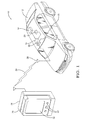
- Fig. 1 is a diagram of a communication system in accordance with one embodiment.
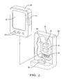
- Fig. 2 is a perspective view of the wireless personal communication device and the wireless personal communication device accessory shown in Fig. 1 in accordance with one embodiment.
- Fig. 1 illustrates a vehicle 12 equipped with an in-vehicle telematics unit 14, hereafter often telematics unit 14.
- the telematics unit 14 may be configured to determine vehicle data such as tire pressure or engine oil life by communicating with an engine control unit (ECU) 16.
- the telematics unit 14 may also be configured to control operation of a vehicle device such as a powered door lock 18 or a vehicle security camera 20.
- the telematics unit 14 may also be equipped with an in-vehicle medium-range RF transceiver 22, hereafter often vehicle transceiver 22.
- the vehicle transceiver 22 may be a RF receive only type device, or a RF transmit only type device.
- a vehicle transceiver having both RF receive and RF transmit capability is preferred to enable a number of features as will be apparent in the description below.
- medium-range means that the RF transceiver broadcasts a RF signal 24 suitable for use at ranges greater than thirty (30) meters and has an effective range of about one thousand (1000) meters. Communication systems with effective ranges of less than one hundred (100) meters are specifically excluded from this definition as they are characterized to be short-range.
- the vehicle transceiver 22 is illustrated has having a vehicle antenna 26, however the illustration is for the purpose of explanation and not limitation, and so it should be appreciated that the antenna 26 may not be visible from outside the vehicle 12.
- the communication system 10 may also include a wireless personal communication device 28, for example a cellular phone or a device commonly known as a smart phone capable of being programmed with various software applications for execution by the operator by pressing buttons 30 or pressing a touch sensitive screen 32 on the wireless personal communication device 28.
- the wireless personal communication device 28 is carried by an operator (not shown) of the vehicle 12, and as will be explained in more detail below, may be used by the operator to communicate with the vehicle 12 while the operator is away from the vehicle 12.
- the communication system 10 may also include a communication device accessory 34, hereafter often accessory 34.
- the accessory 34 is detachably coupled to the wireless personal communication device 28 so that the accessory can be readily detached and reattached to the wireless personal communication device 28.
- the accessory 34 is illustrated as having an antenna 36 for the purposes of explanation and not limitation, and so it is understood that the antenna 36 may not be visible from outside the accessory 34.
- Fig. 2 illustrates a non-limiting example of the accessory 34 detached from the wireless personal communication device 28 for the purpose of explanation.
- the accessory 34 is generally defined by a frame 35 configured to be readily attached and detached to the wireless personal communication device 28.
- the frame 35 may include clips or tabs or other known means for making attaching and detaching the accessory 34 convenient.
- the accessory 34 is electrically connected to the wireless personal communication device 28 so the accessory 34 can receive electrical power from the wireless personal communication device 28.
- the accessory 34 may include a connector 36 that connects to a matching connector (not specifically shown) on the wireless personal communication device 28.
- a connector is generally configured to connect to a battery 40 within the wireless personal communication device 28 in order for the accessory 34 to draw electrical power from the battery 40.
- the accessory 34 may be equipped with a portable medium-range RF transceiver 38, hereafter often portable transceiver 38, which is configured to communicate directly with the vehicle transceiver 22.
- a portable medium-range RF transceiver 38 hereafter often portable transceiver 38, which is configured to communicate directly with the vehicle transceiver 22.
- the definition of medium-range given above with regard to vehicle transceiver 22 also applies to the portable transceiver 38.
- communicate directly means that there is no other device or system facilitating communications between the vehicle transceiver 22 and the portable transceiver 38.
- communications networks such as cell-phone networks and repeater stations are specifically excluded as they are examples of communication that is not direct communication. It will be appreciated that by providing direct communication, subscription fees normally associated with vehicle communication services such as On-Star and/or cellular phone services are avoided.
- the wireless personal communication device 28 may be configured to communicate with the portable transmitter 38 so that an operator could transmit a command via the portable transmitter 38, or display a message or information received by the portable transceiver 38.
- the communication between the wireless personal communication device 28 and the portable transceiver 38 may be wireless communication, for example Bluetooth, or may be wired communication via the connector 36.
- the accessory 34 may be electrically coupled to the wireless personal communication device 28 via a wired connection that provides an electrical power connection and a data connection between the accessory 34 and the wireless personal communication device 28.
- the wireless personal communication device 28 can communicate directly with the in-vehicle telematics unit 14 in a manner effective for the wireless personal communication device 28 to display vehicle data such as an image captured by the vehicle security camera 20, and/or control operation of a vehicle device such as the powered door lock 18.
- vehicle data such as an image captured by the vehicle security camera 20, and/or control operation of a vehicle device such as the powered door lock 18.
- both the accessory 34 and telematics unit 14 may be equipped with two-way communications devices so that a confirmation signal can be sent from the vehicle to the wireless personal communication device 28 following the operator transmitting a command signal to the vehicle 12.
- the accessory 34 may also be equipped with a near field communications (NFC) device 42.
- the NFC device may be an autonomous device such as is used to initiate a financial transaction at a fuel pump.
- the NFC device may also be electronically coupled to the wireless personal communication device 28 so that the specific information transmitted by the NFC device can be customized as needed.
- the accessory 34 may also include a secondary battery 44 to backup and/or supplement the battery 40 within the wireless personal communication device 28.
- the accessory 34 may also include a secondary charging means such as an inductive device 46 capable of generating a charging voltage that is applied to the battery 40 and/or the secondary battery 44 when the inductive device 46 is placed in or near an alternating magnetic field.
- a communication system 10 a wireless personal communication device accessory 34 is provided.
- the effective range for communication with the vehicle 12 is extended.
- Such extended range allows a vehicle operator to, for example, remotely start the vehicle 12 from a distance, e.g. within a workplace or shopping place, so that the vehicle interior has ample time to warm up before the operator arrives at the vehicle 12.
- Such a communication system 10 may also be used to verify that the vehicle is still where is was parked, remotely determine if the vehicle needs to be serviced, remotely download music or other entertainment data, or remotely view the area surrounding the vehicle for security or safety reasons.
- the operator Since the operator likely already regularly charges the battery 40 within the wireless personal communication device 28, the problem of having to recharge or replace batteries in a medium range key fob, or equip the key fob with undesirably large batteries is overcome. Furthermore, by coupling the key fob functions to the wireless personal communication device 28, the operator only needs to carry one device instead of a separate smart phone and key fob.
Landscapes
- Physics & Mathematics (AREA)
- General Physics & Mathematics (AREA)
- Engineering & Computer Science (AREA)
- Computer Networks & Wireless Communication (AREA)
- Lock And Its Accessories (AREA)
- Near-Field Transmission Systems (AREA)
Abstract
Description
- The invention generally relates to a communication system for communicating with a vehicle, and more particularly relates to a wireless personal communication device accessory configured to enable communications between a wireless personal communication device such as a smart phone and an in-vehicle telematics unit electrically coupled to the vehicle electrical system.
- Many vehicles are equipped with remote keyless entry (RKE) systems configured to operate vehicle devices such as a vehicle-door lock/unlock system or a remote vehicle engine starting system. Such RKE systems typically use a key fob equipped with a low-power, short-range radio-frequency (RF) transmitter activated by an operator of the vehicle pressing a button on the key fob. In general, the power transmitted by the RF transmitter is intentionally limited in order to prolong battery life, and so most RKE systems have limited effective ranges, less than thirty (30) meters for example. Increasing transmit power in order to increase the effective range requires larger batteries to extend battery life, or requires frequent changing or recharging of the key fob batteries. Larger batteries undesirably increases key fob size and weight, and frequent changing or charging is inconvenient and increases the risk of the key fob being inoperative due to discharged batteries.
- In accordance with one embodiment of this invention, a communication system for communicating with a vehicle is provided. The system includes an in-vehicle telematics unit, a wireless personal communication device, and a communication device accessory. The in-vehicle telematics unit is configured to determine vehicle data and control operation of a vehicle device. The in-vehicle telematics unit is equipped with an in-vehicle medium-range RF transceiver. The wireless personal communication device is carried by an operator of the vehicle. The communication device accessory is detachably coupled and electrically connected to the wireless personal communication device in a manner effective to receive electrical power from the wireless personal communication device. The communication device accessory is equipped with a portable medium-range RF transceiver configured to communicate directly with the in-vehicle medium-range RF transceiver such that the wireless personal communication device can communicate directly with the in-vehicle telematics unit in a manner effective for the wireless personal communication device to display the vehicle data and control operation of the vehicle device.
- In another embodiment of the present invention, a wireless personal communication device accessory is provided. The accessory includes a frame and a portable medium-range RF transceiver. The frame is configured to detachably couple and electrically connect the accessory to a wireless personal communication device in a manner effective to receive electrical power from the wireless personal communication device. The portable medium-range RF transceiver is configured to communicate directly with an in-vehicle medium-range RF transceiver such that the wireless personal communication device can communicate directly with an in-vehicle telematics unit in a manner effective for the wireless personal communication device to display the vehicle data and control operation of the vehicle device.
- Further features and advantages of the invention will appear more clearly on a reading of the following detailed description of the preferred embodiment of the invention, which is given by way of non-limiting example only and with reference to the accompanying drawings.
- The present invention will now be described, by way of example with reference to the accompanying drawings, in which:
-
Fig. 1 is a diagram of a communication system in accordance with one embodiment; and -
Fig. 2 is a perspective view of the wireless personal communication device and the wireless personal communication device accessory shown inFig. 1 in accordance with one embodiment. - In accordance with an embodiment of a
communication system 10,Fig. 1 illustrates avehicle 12 equipped with an in-vehicle telematics unit 14, hereafter oftentelematics unit 14. Thetelematics unit 14 may be configured to determine vehicle data such as tire pressure or engine oil life by communicating with an engine control unit (ECU) 16. Thetelematics unit 14 may also be configured to control operation of a vehicle device such as a powereddoor lock 18 or avehicle security camera 20. Thetelematics unit 14 may also be equipped with an in-vehicle medium-range RF transceiver 22, hereafter oftenvehicle transceiver 22. Thevehicle transceiver 22 may be a RF receive only type device, or a RF transmit only type device. However, a vehicle transceiver having both RF receive and RF transmit capability is preferred to enable a number of features as will be apparent in the description below. As used herein, medium-range means that the RF transceiver broadcasts aRF signal 24 suitable for use at ranges greater than thirty (30) meters and has an effective range of about one thousand (1000) meters. Communication systems with effective ranges of less than one hundred (100) meters are specifically excluded from this definition as they are characterized to be short-range. Thevehicle transceiver 22 is illustrated has having avehicle antenna 26, however the illustration is for the purpose of explanation and not limitation, and so it should be appreciated that theantenna 26 may not be visible from outside thevehicle 12. - The
communication system 10 may also include a wirelesspersonal communication device 28, for example a cellular phone or a device commonly known as a smart phone capable of being programmed with various software applications for execution by the operator by pressingbuttons 30 or pressing a touchsensitive screen 32 on the wirelesspersonal communication device 28. In general, the wirelesspersonal communication device 28 is carried by an operator (not shown) of thevehicle 12, and as will be explained in more detail below, may be used by the operator to communicate with thevehicle 12 while the operator is away from thevehicle 12. Thecommunication system 10 may also include acommunication device accessory 34, hereafter oftenaccessory 34. In general, theaccessory 34 is detachably coupled to the wirelesspersonal communication device 28 so that the accessory can be readily detached and reattached to the wirelesspersonal communication device 28. Theaccessory 34 is illustrated as having anantenna 36 for the purposes of explanation and not limitation, and so it is understood that theantenna 36 may not be visible from outside theaccessory 34. -
Fig. 2 illustrates a non-limiting example of theaccessory 34 detached from the wirelesspersonal communication device 28 for the purpose of explanation. Theaccessory 34 is generally defined by aframe 35 configured to be readily attached and detached to the wirelesspersonal communication device 28. Theframe 35 may include clips or tabs or other known means for making attaching and detaching theaccessory 34 convenient. In general, theaccessory 34 is electrically connected to the wirelesspersonal communication device 28 so theaccessory 34 can receive electrical power from the wirelesspersonal communication device 28. In one embodiment, theaccessory 34 may include aconnector 36 that connects to a matching connector (not specifically shown) on the wirelesspersonal communication device 28. Such a connector is generally configured to connect to abattery 40 within the wirelesspersonal communication device 28 in order for theaccessory 34 to draw electrical power from thebattery 40. - The
accessory 34 may be equipped with a portable medium-range RF transceiver 38, hereafter oftenportable transceiver 38, which is configured to communicate directly with thevehicle transceiver 22. The definition of medium-range given above with regard tovehicle transceiver 22 also applies to theportable transceiver 38. As used herein, communicate directly means that there is no other device or system facilitating communications between thevehicle transceiver 22 and theportable transceiver 38. As such, communications networks such as cell-phone networks and repeater stations are specifically excluded as they are examples of communication that is not direct communication. It will be appreciated that by providing direct communication, subscription fees normally associated with vehicle communication services such as On-Star and/or cellular phone services are avoided. - The wireless
personal communication device 28 may be configured to communicate with theportable transmitter 38 so that an operator could transmit a command via theportable transmitter 38, or display a message or information received by theportable transceiver 38. The communication between the wirelesspersonal communication device 28 and theportable transceiver 38 may be wireless communication, for example Bluetooth, or may be wired communication via theconnector 36. As such, theaccessory 34 may be electrically coupled to the wirelesspersonal communication device 28 via a wired connection that provides an electrical power connection and a data connection between theaccessory 34 and the wirelesspersonal communication device 28. With such an arrangement, the wirelesspersonal communication device 28 can communicate directly with the in-vehicle telematics unit 14 in a manner effective for the wirelesspersonal communication device 28 to display vehicle data such as an image captured by thevehicle security camera 20, and/or control operation of a vehicle device such as the powereddoor lock 18. - When an vehicle operator uses a short-range communication device such as a key fob to operate a vehicle device such as the powered
door lock 18, the operator can readily confirm that the powereddoor lock 18 operated either by hearing the sound of the powereddoor lock 18 actuating, or by a vehicle generated confirmation indication such as flashing lights on the vehicle or sounding a vehicle horn. However, if theaccessory 34 is equipped with a medium-range transmitter or transceiver, the operator may transmit a signal to lock or unlock the vehicle doors while being located where the operator cannot observe that the powereddoor lock 18 actually operated. As such, it may be preferable for both theaccessory 34 andtelematics unit 14 to be equipped with two-way communications devices so that a confirmation signal can be sent from the vehicle to the wirelesspersonal communication device 28 following the operator transmitting a command signal to thevehicle 12. - Continuing to refer to
Fig. 2 , theaccessory 34 may also be equipped with a near field communications (NFC)device 42. The NFC device may be an autonomous device such as is used to initiate a financial transaction at a fuel pump. The NFC device may also be electronically coupled to the wirelesspersonal communication device 28 so that the specific information transmitted by the NFC device can be customized as needed. - The
accessory 34 may also include asecondary battery 44 to backup and/or supplement thebattery 40 within the wirelesspersonal communication device 28. Theaccessory 34 may also include a secondary charging means such as aninductive device 46 capable of generating a charging voltage that is applied to thebattery 40 and/or thesecondary battery 44 when theinductive device 46 is placed in or near an alternating magnetic field. - Accordingly, a
communication system 10, a wireless personalcommunication device accessory 34 is provided. By equipping thecommunication system 10 with medium-range transceivers vehicle 12 is extended. Such extended range allows a vehicle operator to, for example, remotely start thevehicle 12 from a distance, e.g. within a workplace or shopping place, so that the vehicle interior has ample time to warm up before the operator arrives at thevehicle 12. Such acommunication system 10 may also be used to verify that the vehicle is still where is was parked, remotely determine if the vehicle needs to be serviced, remotely download music or other entertainment data, or remotely view the area surrounding the vehicle for security or safety reasons. Since the operator likely already regularly charges thebattery 40 within the wirelesspersonal communication device 28, the problem of having to recharge or replace batteries in a medium range key fob, or equip the key fob with undesirably large batteries is overcome. Furthermore, by coupling the key fob functions to the wirelesspersonal communication device 28, the operator only needs to carry one device instead of a separate smart phone and key fob. - While this invention has been described in terms of the preferred embodiments thereof, it is not intended to be so limited, but rather only to the extent set forth in the claims that follow.
Claims (12)
- A communication system (10) for communicating with a vehicle (12) comprising:an in-vehicle telematics unit (14) configured to determine vehicle data and control operation of a vehicle device (18), said in-vehicle telematics unit (14) equipped with an in-vehicle medium-range RF transceiver (22);a wireless personal communication device (28) carried by an operator of the vehicle (12); anda communication device accessory (34) detachably coupled and electrically connected to the wireless personal communication device (28) in a manner effective to receive electrical power from the wireless personal communication device (28), said communication device accessory (34) equipped with a portable medium-range RF transceiver (38) configured to communicate directly with the in-vehicle medium-range RF transceiver (22) such that the wireless personal communication device (28) can communicate directly with the in-vehicle telematics unit (14) in a manner effective for the wireless personal communication device (28) to display the vehicle data and control operation of the vehicle device (18).
- The system (10) in accordance with claim 1, wherein the communication device accessory (34) is electrically coupled to the wireless personal communication device (28) via a wired connection that provides a power connection and a data connection between the communication device accessory (34) and the wireless personal communication device (28).
- The system (10) in accordance with claim 1, wherein the communication device accessory (34) further comprises a near field communications device (42).
- The system (10) in accordance with claim 3, wherein the near field communications device (42) is electrically coupled to the wireless personal communication device (28).
- The system (10) in accordance with claim 1, wherein the communication device accessory (34) further comprises a secondary battery (44).
- The system (10) in accordance with claim 1, wherein the communication device accessory (34) further comprises a secondary charging means (46).
- A wireless personal communication device accessory (34) comprising:a frame (35) configured to detachably couple and electrically connect the accessory (34) to a wireless personal communication device (28) in a manner effective to receive electrical power from the wireless personal communication device (28);a portable medium-range RF transceiver (38) configured to communicate directly with an in-vehicle medium-range RF transceiver (22) such that the wireless personal communication device (28) can communicate directly with an in-vehicle telematics unit (14) in a manner effective for the wireless personal communication device (28) to display the vehicle data and control operation of the vehicle device (18).
- The communication device accessory (34) in accordance with claim 7, wherein the communication device accessory (34) is electrically coupled to the wireless personal communication device (28) via a wired connection that provides a power connection and a data connection between the communication device accessory (34) and the wireless personal communication device (28).
- The communication device accessory (34) in accordance with claim 7, wherein the communication device accessory (34) further comprises a near field communications device (42).
- The communication device accessory (34) in accordance with claim 9, wherein the near field communications device (42) is electrically coupled to the wireless personal communication device (28).
- The communication device accessory (34) in accordance with claim 7, wherein the communication device accessory (34) further comprises a secondary battery (44).
- The communication device accessory (34) in accordance with claim 7, wherein the communication device accessory (34) is further configured to cooperate with a secondary charging means (46).
Applications Claiming Priority (1)
| Application Number | Priority Date | Filing Date | Title |
|---|---|---|---|
| US12/981,876 US20120172010A1 (en) | 2010-12-30 | 2010-12-30 | Medium range vehicle communication system |
Publications (2)
| Publication Number | Publication Date |
|---|---|
| EP2472478A2 true EP2472478A2 (en) | 2012-07-04 |
| EP2472478A3 EP2472478A3 (en) | 2015-10-07 |
Family
ID=45464270
Family Applications (1)
| Application Number | Title | Priority Date | Filing Date |
|---|---|---|---|
| EP11194450.0A Withdrawn EP2472478A3 (en) | 2010-12-30 | 2011-12-20 | Medium range vehicle communication system |
Country Status (2)
| Country | Link |
|---|---|
| US (1) | US20120172010A1 (en) |
| EP (1) | EP2472478A3 (en) |
Cited By (5)
| Publication number | Priority date | Publication date | Assignee | Title |
|---|---|---|---|---|
| WO2015177298A1 (en) * | 2014-05-21 | 2015-11-26 | Huf Hülsbeck & Fürst Gmbh & Co. Kg | Module unit with interface for a communications device |
| CN105383441A (en) * | 2014-09-03 | 2016-03-09 | 福特全球技术公司 | Vehicle initiated remote engine start |
| CN105706378A (en) * | 2013-11-08 | 2016-06-22 | Gogo有限责任公司 | Method for optimizing use of a modem on a conveyance in which a processor determines a port status of a conveyance and a wireless communication link is in a receive state with a bandwidth greater than that of a reverse link |
| EP3503514A4 (en) * | 2016-08-18 | 2020-04-15 | LG Electronics Inc. -1- | MOBILE TERMINAL AND METHOD FOR CONTROLLING SAID MOBILE TERMINAL |
| DE102012205128B4 (en) * | 2011-04-04 | 2020-08-13 | General Motors Llc | Method of using a smartphone as a telematics device interface |
Families Citing this family (23)
| Publication number | Priority date | Publication date | Assignee | Title |
|---|---|---|---|---|
| JP5879113B2 (en) * | 2011-12-09 | 2016-03-08 | 富士通テン株式会社 | Remote starter and remote start system |
| US8855621B2 (en) * | 2012-05-01 | 2014-10-07 | Innova Electronics, Inc. | Cellphone controllable car intrusion recording and monitoring reaction system |
| US20140210592A1 (en) * | 2013-01-25 | 2014-07-31 | Ford Global Technologies, Llc | Apparatus and method for interfacing a wireless communication device to a communication device keypad in a vehicle |
| US20140304170A1 (en) * | 2013-03-15 | 2014-10-09 | First National Of Nebraska, Inc. | Remote credit issuance system |
| DE102013006070A1 (en) * | 2013-04-08 | 2014-10-09 | Audi Ag | Method and device for transmitting vehicle-specific information to a user's terminal by means of wireless communication |
| US8930045B2 (en) | 2013-05-01 | 2015-01-06 | Delphi Technologies, Inc. | Relay attack prevention for passive entry passive start (PEPS) vehicle security systems |
| US9842444B2 (en) * | 2014-06-11 | 2017-12-12 | Ford Global Technologies, Llc | Phone sleeve vehicle fob |
| US20150377154A1 (en) * | 2014-06-30 | 2015-12-31 | International Engine Intellectual Property Company, Llc | Temporary rental of engine recalibration |
| KR102241297B1 (en) * | 2014-08-27 | 2021-04-16 | 삼성전자주식회사 | Method for controlling and an electronic device thereof |
| US9460571B2 (en) | 2014-10-17 | 2016-10-04 | Ford Global Technologies, Llc | Backup key for multiple backup key integration into a mobile device case |
| US10162347B2 (en) * | 2015-04-20 | 2018-12-25 | Lg Electronics Inc. | Mobile terminal and method for controlling the same |
| US10504094B1 (en) | 2016-02-16 | 2019-12-10 | State Farm Mutual Automobile Insurance Company | Connected car as a payment device |
| US10949831B1 (en) | 2016-02-16 | 2021-03-16 | State Farm Mutual Automobile Insurance Company | Connected vehicle for providing navigation directions to merchant terminals that process vehicle payments |
| US10949830B1 (en) | 2016-02-16 | 2021-03-16 | State Farm Mutual Automobile Insurance Company | Merchant terminal for receiving payment from a vehicle |
| WO2017144348A1 (en) * | 2016-02-26 | 2017-08-31 | Huf Hülsbeck & Fürst Gmbh & Co. Kg | Module unit comprising an interface for a communication device |
| WO2017155530A1 (en) * | 2016-03-10 | 2017-09-14 | Ford Global Technologies, Llc | In-vehicle banking enabled by near field communication |
| US10091633B2 (en) | 2016-10-24 | 2018-10-02 | Lear Corporation | Passive entry passive start systems employing consumer mobile devices as portable remote control units |
| DE102018105443A1 (en) * | 2017-03-13 | 2018-09-13 | Huf Hülsbeck & Fürst Gmbh & Co. Kg | Safety procedure for a safety system of a vehicle |
| US11598838B2 (en) | 2019-06-26 | 2023-03-07 | Aptiv Technologies Limited | Detection device |
| US10664932B1 (en) * | 2019-12-30 | 2020-05-26 | Michael A. Racusin | Online system for retail gas sales |
| US11617074B2 (en) * | 2020-06-15 | 2023-03-28 | Toyota Motor North America, Inc. | Secure boundary area communication systems and methods |
| EP4071730A1 (en) * | 2021-04-07 | 2022-10-12 | BKS GmbH | Device, arrangement and set |
| EP4449388A1 (en) * | 2021-12-13 | 2024-10-23 | Porsentech Aps | Detection case for portable device |
Family Cites Families (16)
| Publication number | Priority date | Publication date | Assignee | Title |
|---|---|---|---|---|
| US5352966A (en) * | 1992-09-11 | 1994-10-04 | Iron Chargers, Inc. | Battery charging device |
| US7031835B2 (en) * | 2000-05-17 | 2006-04-18 | Omega Patents, L.L.C. | Vehicle tracker cooperating with a starter interrupt and related methods |
| US6792296B1 (en) * | 2002-10-01 | 2004-09-14 | Motorola, Inc. | Portable wireless communication device and methods of configuring same when connected to a vehicle |
| US7146129B2 (en) * | 2003-07-10 | 2006-12-05 | Lucent Technologies Inc. | Remote control of functions via wireless transmission of text-based messages |
| US7805169B2 (en) * | 2004-09-08 | 2010-09-28 | At&T Intellectual Property I, L.P. | Methods, systems, and key fob apparatuses for facilitating hands free mobile communications from within an automotive vehicle |
| US7224262B2 (en) * | 2004-09-21 | 2007-05-29 | Bayerische Motoren Werke Aktiengesellschaft | Wireless vehicle control system and method |
| US7119695B2 (en) * | 2004-11-15 | 2006-10-10 | Pro Tech Monitoring, Inc. | Advanced house arrest tracker system |
| DE102005008285B3 (en) * | 2005-02-23 | 2006-09-28 | Bury Sp.Z.O.O | Navigation device for vehicles |
| US20080004003A1 (en) * | 2006-06-28 | 2008-01-03 | Thomas Wulff | Mobile device with detachable accessory |
| WO2008064490A1 (en) * | 2006-12-01 | 2008-06-05 | Intelligent Mechatronics Systems Inc. | Vehicle communication device |
| US20080197970A1 (en) * | 2007-02-15 | 2008-08-21 | Lear Corporation | Remote access system |
| JP4391546B2 (en) * | 2007-04-06 | 2009-12-24 | 三菱電機株式会社 | Vehicle communication system |
| US7821383B2 (en) * | 2007-10-10 | 2010-10-26 | Delphi Technologies, Inc. | Apparatus for medium-range vehicle communications and control |
| US7778186B2 (en) * | 2007-10-10 | 2010-08-17 | Delphi Technologies, Inc. | Fault tolerant vehicle communication and control apparatus |
| US7912441B2 (en) * | 2007-12-11 | 2011-03-22 | Motorola Mobility, Inc. | Apparatus and method for enabling near field communication equipment in a portable communications device |
| US8688037B2 (en) * | 2008-09-26 | 2014-04-01 | Hewlett-Packard Development Company, L.P. | Magnetic latching mechanism for use in mating a mobile computing device to an accessory device |
-
2010
- 2010-12-30 US US12/981,876 patent/US20120172010A1/en not_active Abandoned
-
2011
- 2011-12-20 EP EP11194450.0A patent/EP2472478A3/en not_active Withdrawn
Non-Patent Citations (1)
| Title |
|---|
| None |
Cited By (8)
| Publication number | Priority date | Publication date | Assignee | Title |
|---|---|---|---|---|
| US10167836B2 (en) | 2011-03-09 | 2019-01-01 | Ford Global Technologies, Llc | Driver initiated remote engine start for vehicle preconditioning having battery charge maintenance priority |
| DE102012205128B4 (en) * | 2011-04-04 | 2020-08-13 | General Motors Llc | Method of using a smartphone as a telematics device interface |
| CN105706378A (en) * | 2013-11-08 | 2016-06-22 | Gogo有限责任公司 | Method for optimizing use of a modem on a conveyance in which a processor determines a port status of a conveyance and a wireless communication link is in a receive state with a bandwidth greater than that of a reverse link |
| CN105706378B (en) * | 2013-11-08 | 2020-02-18 | Gogo有限责任公司 | Method and hybrid communication system for optimizing the use of a modem on a vehicle |
| WO2015177298A1 (en) * | 2014-05-21 | 2015-11-26 | Huf Hülsbeck & Fürst Gmbh & Co. Kg | Module unit with interface for a communications device |
| CN105383441A (en) * | 2014-09-03 | 2016-03-09 | 福特全球技术公司 | Vehicle initiated remote engine start |
| CN105383441B (en) * | 2014-09-03 | 2019-10-22 | 福特全球技术公司 | remote vehicle engine start |
| EP3503514A4 (en) * | 2016-08-18 | 2020-04-15 | LG Electronics Inc. -1- | MOBILE TERMINAL AND METHOD FOR CONTROLLING SAID MOBILE TERMINAL |
Also Published As
| Publication number | Publication date |
|---|---|
| US20120172010A1 (en) | 2012-07-05 |
| EP2472478A3 (en) | 2015-10-07 |
Similar Documents
| Publication | Publication Date | Title |
|---|---|---|
| US20120172010A1 (en) | Medium range vehicle communication system | |
| US9842444B2 (en) | Phone sleeve vehicle fob | |
| CN209904701U (en) | Vehicle control system matched with intelligent key | |
| US20100198428A1 (en) | Multi-purpose fob system | |
| JP5081783B2 (en) | Vehicle charging system | |
| CN105917586B (en) | Bluetooth authentication for vehicle access systems | |
| CN106341147B (en) | Intelligent vehicle-mounted system based on mobile terminal | |
| US8692651B2 (en) | Range extending positive repeater | |
| EP2048626A2 (en) | Apparatus for medium-range vehicle communications and control | |
| JP2013106338A (en) | Bluetooth-equipped keyless entry system | |
| KR20150029056A (en) | Universal vehicle remote control device and method | |
| CN103296534A (en) | Plug lock device | |
| CN110944884B (en) | Mobile identification transmitter | |
| KR20150072138A (en) | Wireless Battery Charging Module of vehicles | |
| JP2012521699A (en) | A remote identification device in combination with a vehicle having means for performing remote communication with the vehicle | |
| CN105302110A (en) | Method for displaying information from an id transmitter | |
| JP2012067530A (en) | Charging system of electronic key | |
| JP4243517B2 (en) | Communications system | |
| JP6066328B2 (en) | Infrared communication system | |
| US8571746B2 (en) | Control system | |
| KR20170015009A (en) | Apparatus for supporting smartkey system of vehicle united with mobile device | |
| WO2019230174A1 (en) | Communication device for vehicle, communication device for parking lot, and parking lot management system | |
| JP2009287350A (en) | Vehicle control system and portable unit holding device | |
| JP2014024458A (en) | Power supply apparatus and portable communication machine retrieval system | |
| KR20150011031A (en) | Smart Key System and Method Thereof |
Legal Events
| Date | Code | Title | Description |
|---|---|---|---|
| AK | Designated contracting states |
Kind code of ref document: A2 Designated state(s): AL AT BE BG CH CY CZ DE DK EE ES FI FR GB GR HR HU IE IS IT LI LT LU LV MC MK MT NL NO PL PT RO RS SE SI SK SM TR |
|
| AX | Request for extension of the european patent |
Extension state: BA ME |
|
| PUAI | Public reference made under article 153(3) epc to a published international application that has entered the european phase |
Free format text: ORIGINAL CODE: 0009012 |
|
| PUAL | Search report despatched |
Free format text: ORIGINAL CODE: 0009013 |
|
| AK | Designated contracting states |
Kind code of ref document: A3 Designated state(s): AL AT BE BG CH CY CZ DE DK EE ES FI FR GB GR HR HU IE IS IT LI LT LU LV MC MK MT NL NO PL PT RO RS SE SI SK SM TR |
|
| AX | Request for extension of the european patent |
Extension state: BA ME |
|
| RIC1 | Information provided on ipc code assigned before grant |
Ipc: G07C 7/00 20060101ALN20150901BHEP Ipc: G07C 5/00 20060101AFI20150901BHEP |
|
| STAA | Information on the status of an ep patent application or granted ep patent |
Free format text: STATUS: THE APPLICATION IS DEEMED TO BE WITHDRAWN |
|
| 18D | Application deemed to be withdrawn |
Effective date: 20160408 |