EP2472405A1 - Handhabung dynamischer und statischer Daten für ein System mit einem nichtflüchtigen Speicher - Google Patents
Handhabung dynamischer und statischer Daten für ein System mit einem nichtflüchtigen Speicher Download PDFInfo
- Publication number
- EP2472405A1 EP2472405A1 EP12150057A EP12150057A EP2472405A1 EP 2472405 A1 EP2472405 A1 EP 2472405A1 EP 12150057 A EP12150057 A EP 12150057A EP 12150057 A EP12150057 A EP 12150057A EP 2472405 A1 EP2472405 A1 EP 2472405A1
- Authority
- EP
- European Patent Office
- Prior art keywords
- nvm
- data
- dynamic
- block
- determining
- Prior art date
- Legal status (The legal status is an assumption and is not a legal conclusion. Google has not performed a legal analysis and makes no representation as to the accuracy of the status listed.)
- Granted
Links
- 230000015654 memory Effects 0.000 title claims abstract description 62
- 230000003068 static effect Effects 0.000 title claims abstract description 51
- 238000000034 method Methods 0.000 claims abstract description 47
- 238000013507 mapping Methods 0.000 claims description 16
- 230000004044 response Effects 0.000 claims description 11
- 238000012544 monitoring process Methods 0.000 claims description 2
- 238000012005 ligant binding assay Methods 0.000 description 81
- 230000008569 process Effects 0.000 description 38
- 238000013519 translation Methods 0.000 description 14
- 238000010586 diagram Methods 0.000 description 7
- 230000006870 function Effects 0.000 description 5
- 238000013459 approach Methods 0.000 description 4
- 230000003321 amplification Effects 0.000 description 2
- 230000008859 change Effects 0.000 description 2
- 230000001351 cycling effect Effects 0.000 description 2
- 239000000203 mixture Substances 0.000 description 2
- 238000003199 nucleic acid amplification method Methods 0.000 description 2
- 238000005201 scrubbing Methods 0.000 description 2
- 230000009286 beneficial effect Effects 0.000 description 1
- 230000001413 cellular effect Effects 0.000 description 1
- 238000005516 engineering process Methods 0.000 description 1
- 230000014759 maintenance of location Effects 0.000 description 1
- 238000005259 measurement Methods 0.000 description 1
- 230000008672 reprogramming Effects 0.000 description 1
- 230000001360 synchronised effect Effects 0.000 description 1
Images


Classifications
-
- G—PHYSICS
- G06—COMPUTING; CALCULATING OR COUNTING
- G06F—ELECTRIC DIGITAL DATA PROCESSING
- G06F12/00—Accessing, addressing or allocating within memory systems or architectures
- G06F12/02—Addressing or allocation; Relocation
- G06F12/0223—User address space allocation, e.g. contiguous or non contiguous base addressing
- G06F12/023—Free address space management
- G06F12/0238—Memory management in non-volatile memory, e.g. resistive RAM or ferroelectric memory
- G06F12/0246—Memory management in non-volatile memory, e.g. resistive RAM or ferroelectric memory in block erasable memory, e.g. flash memory
-
- G—PHYSICS
- G06—COMPUTING; CALCULATING OR COUNTING
- G06F—ELECTRIC DIGITAL DATA PROCESSING
- G06F12/00—Accessing, addressing or allocating within memory systems or architectures
-
- G—PHYSICS
- G06—COMPUTING; CALCULATING OR COUNTING
- G06F—ELECTRIC DIGITAL DATA PROCESSING
- G06F2212/00—Indexing scheme relating to accessing, addressing or allocation within memory systems or architectures
- G06F2212/10—Providing a specific technical effect
- G06F2212/1032—Reliability improvement, data loss prevention, degraded operation etc
-
- G—PHYSICS
- G06—COMPUTING; CALCULATING OR COUNTING
- G06F—ELECTRIC DIGITAL DATA PROCESSING
- G06F2212/00—Indexing scheme relating to accessing, addressing or allocation within memory systems or architectures
- G06F2212/10—Providing a specific technical effect
- G06F2212/1041—Resource optimization
- G06F2212/1044—Space efficiency improvement
-
- G—PHYSICS
- G06—COMPUTING; CALCULATING OR COUNTING
- G06F—ELECTRIC DIGITAL DATA PROCESSING
- G06F2212/00—Indexing scheme relating to accessing, addressing or allocation within memory systems or architectures
- G06F2212/72—Details relating to flash memory management
- G06F2212/7205—Cleaning, compaction, garbage collection, erase control
-
- G—PHYSICS
- G06—COMPUTING; CALCULATING OR COUNTING
- G06F—ELECTRIC DIGITAL DATA PROCESSING
- G06F2212/00—Indexing scheme relating to accessing, addressing or allocation within memory systems or architectures
- G06F2212/72—Details relating to flash memory management
- G06F2212/7211—Wear leveling
Definitions
- NAND flash memory as well as other types of non-volatile memories (“NVMs”), are commonly used for mass storage.
- consumer electronics such as portable media players often include flash memory to store music, videos, and other media.
- a NVM may include both data that is needed by an electronic device (e.g., "valid data”) and data that is no longer needed by the electronic device (e.g., "invalid data”).
- Valid data stored in a NVM can further be separated into data that is frequently updated or changed (e.g., "dynamic data”) and data that is rarely updated or changed (e.g., "static data”).
- dynamic data data that is frequently updated or changed
- static data data that is rarely updated or changed
- Some NVMs are configured such that a block of programmed memory locations needs to be erased before any of the memory locations in the block can be reprogrammed. Therefore, electronic devices typically perform an operation referred to as “garbage collection" ("GC") to free up blocks for erasing and reprogramming. To free up all of the memory locations in that block for erasing, the electronic device may copy the block's valid data into memory locations of another block. Because there is a mixture of dynamic and static data on a block, the efficiency of GC can be low because the amount of valid data that has to be copied may be significant.
- GC garbage collection
- wear leveling is generally used to extend the useful life of the NVM.
- systems may perform unnecessary wear leveling of the NVM, which may in fact result in more wear of the NVM.
- Systems and methods are disclosed for handling dynamic and static data for a system having non-volatile memory. By determining whether data being written to the NVM is dynamic, a NVM interface of a system can determine where to initially place data on the NVM. Moreover, this allows the NVM interface to improve the efficiencies of both garbage collection and wear leveling.
- FIGS. 1 and 2 are block diagrams of electronic devices configured in accordance with various embodiments of the invention.
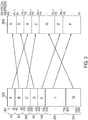
- FIG. 3 is a block diagram of an illustrative mapping of logical block addresses to physical pages in accordance with various embodiments of the invention
- FIG. 4 is a block diagram of an illustrative tree used for providing logical to physical address mappings in accordance with various embodiments of the invention
- FIG. 5 is a graphical view of metadata that can be associated with user data in accordance with various embodiments of the invention.
- FIG. 6 is a flowchart of an illustrative process for programming data to a non-volatile memory in accordance with various embodiments of the invention.
- FIG. 7 is a flowchart of an illustrative process for performing garbage collection on a non-volatile memory in accordance with various embodiments of the invention.
- FIG. 8 is a flowchart of an illustrative process for determining whether to perform wear leveling on a non-volatile memory in accordance with various embodiments of the invention.
- NVM non-volatile memory
- the NVM interface in response to receiving a write request corresponding to a logical block address (“LBA") range, can determine whether data associated with the LBA range is dynamic. In some embodiments, the NVM interface can make this determination based on one or more parameters obtained from a tree or metadata.
- the one or more parameters can be any suitable parameter such as, for example, a counter indicating the number of times a particular LBA range has been written, a user weave sequence indicating when data was last written to a LBA range by an application and/or operating system, a weave sequence indicating when data was last written to a LBA range by any source (e.g., by a GC process or by an application or operating system), and/or any combination thereof.
- the NVM interface can program the data to either a dynamic stream block or a static stream block.
- a "dynamic stream block” may be any suitable block of the NVM that has been assigned by the NVM interface as part of a dynamic stream. Incoming data that is classified as dynamic may be selectively placed on one or more dynamic blocks.
- a "static stream block” may be any suitable block of the NVM that has been assigned by the NVM interface as part of a static stream. Incoming data that is classified as static may be selectively placed on one or more static blocks.
- GC write amplification can be reduced and the efficiency of GC can consequently be improved.
- determination of whether data is dynamic allows the NVM interface to avoid unnecessary wear leveling of the NVM.
- FIG. 1 illustrates a block diagram of electronic device 100.
- electronic device 100 can be or can include a portable media player, a cellular telephone, a pocket-sized personal computer, a personal digital assistance ("PDA"), a desktop computer, a laptop computer, and any other suitable type of electronic device.
- PDA personal digital assistance
- Non-volatile memory 120 can include a NAND flash memory based on floating gate or charge trapping technology, NOR flash memory, erasable programmable read only memory (“EPROM”), electrically erasable programmable read only memory (“EEPROM”), Ferroelectric RAM (“FRAM”), magnetoresistive RAM (“MRAM”), or any combination thereof.
- SoC system-on-a-chip
- NVM non-volatile memory
- Non-volatile memory 120 can include a NAND flash memory based on floating gate or charge trapping technology, NOR flash memory, erasable programmable read only memory (“EPROM”), electrically erasable programmable read only memory (“EEPROM”), Ferroelectric RAM (“FRAM”), magnetoresistive RAM (“MRAM”), or any combination thereof.
- NVM 120 can be organized into "blocks”, which can the smallest erasable unit, and further organized into "pages", which can be the smallest unit that can be programmed or read.
- NVM 120 can include multiple integrated circuits, where each integrated circuit may have multiple blocks. Memory locations (e.g., blocks or pages of blocks) from corresponding integrated circuits may form "super blocks”. Each memory location (e.g., page or block) of NVM 120 can be referenced using a physical address (e.g., a physical page address or physical block address).
- System-on-a-chip 110 can include SoC control circuitry 112, memory 114, and NVM interface 118.
- SoC control circuitry 112 can control the general operations and functions of SoC 110 and the other components of SoC 110 or device 100. For example, responsive to user inputs and/or the instructions of an application or operating system, SoC control circuitry 112 can issue read or write requests to NVM interface 118 to obtain data from or store data in NVM 120.
- data that SoC control circuitry 112 may request for storage or retrieval may be referred to as "user data", even though the data may not be directly associated with a user or user application. Rather, the user data can be any suitable sequence of digital information generated or obtained by SoC control circuitry 112 (e.g., via an application or operating system).
- SoC control circuitry 112 can include any combination of hardware, software, and firmware, and any components, circuitry, or logic operative to drive the functionality of electronic device 100.
- SoC control circuitry 112 can include one or more processors that operate under the control of software/firmware stored in NVM 120 or memory 114.
- Memory 114 can include any suitable type of volatile memory, such as random access memory (“RAM”) (e.g., static RAM (“SRAM”), dynamic random access memory (“DRAM”), synchronous dynamic random access memory (“SDRAM”), double-data-rate (“DDR”) RAM), cache memory, read-only memory (“ROM”), or any combination thereof.
- RAM random access memory
- DRAM dynamic random access memory
- SDRAM synchronous dynamic random access memory
- DDR double-data-rate
- ROM read-only memory
- Memory 114 can include a data source that can temporarily store user data for programming into or reading from non-volatile memory 120.
- memory 114 may act as the main memory for any processors implemented as part of SoC control circuitry 112.
- NVM interface 118 may include any suitable combination of hardware, software, and/or firmware configured to act as an interface or driver between SoC control circuitry 112 and NVM 120.
- SoC control circuitry 112 For any software modules included in NVM interface 118, corresponding program code may be stored in NVM 120 or memory 114.
- NVM interface 118 can perform a variety of functions that allow SoC control circuitry 112 to access NVM 120 and to manage the memory locations (e.g., pages, blocks, super blocks, integrated circuits) of NVM 120 and the data stored therein (e.g., user data). For example, NVM interface 118 can interpret the read or write requests from SoC control circuitry 112, perform wear leveling, and generate read and program instructions compatible with the bus protocol of NVM 120.
- SoC control circuitry 112 can access NVM 120 and to manage the memory locations (e.g., pages, blocks, super blocks, integrated circuits) of NVM 120 and the data stored therein (e.g., user data).
- NVM interface 118 can interpret the read or write requests from SoC control circuitry 112, perform wear leveling, and generate read and program instructions compatible with the bus protocol of NVM 120.
- NVM interface 118 and SoC control circuitry 112 are shown as separate modules, this is intended only to simplify the description of the embodiments of the invention. It should be understood that these modules may share hardware components, software components, or both.
- SoC control circuitry 112 may execute a software-based memory driver for NVM interface 118.
- electronic device 100 can include a target device, such as a flash memory drive or SD card, that includes NVM 120 and some or all portions of NVM interface 118.
- SoC 110 or SoC control circuitry 112 may act as the host controller for the target device. For example, as the host controller, SoC 110 can issue read and write requests to the target device.
- FIG. 2 illustrates a block diagram of electronic device 200, which may illustrate in greater detail some of the firmware, software, and/or hardware components of electronic device 100 ( FIG. 1 ) in accordance with various embodiments.
- Electronic device 200 may have any of the features and functionalities described above in connection with FIG. 1 , and vice versa. As shown, dashed lines demarcate the layers. It is understood that the depiction of which components fall within the demarcation lines are merely illustrative and that one or more components can be affiliated with a different layer.
- Electronic device 200 can include file system 210, NVM driver 212, NVM bus controller 216, and NVM 220.
- file system 210 and NVM driver 212 may be software or firmware modules
- NVM bus controller 216 and NVM 220 may be hardware modules.
- NVM driver 212 may represent the software or firmware aspect of NVM interface 218, and NVM bus controller 216 may represent the hardware aspect of NVM interface 218.
- File system 210 can include any suitable type of file system, such as a File Allocation Table ("FAT”) file system or a Hierarchical File System Plus (“HFS+”), and may be part of the operating system of electronic device 200 (e.g., part of SoC control circuitry 112 of FIG. 1 ).
- file system 210 may include a flash file system, which provides a logical to physical mapping of pages.
- file system 210 may perform some or all of the functionalities of NVM driver 212 discussed below, and therefore file system 210 and NVM driver 212 may or may not be separate modules.
- File system 210 may manage file and folder structures for the application and operating system.
- File system 210 may operate under the control of an application or operating system running on electronic device 200, and may provide write and read requests to NVM driver 212 when the application or operating system requests that information be read from or stored in NVM 220.
- file system 210 can provide a logical address to indicate where the user data should be read from or written to, such as a logical page address or a logical block address with a page offset.
- File system 210 may provide read and write requests to NVM driver 212 that are not directly compatible with NVM 220.
- the logical addresses may use conventions or protocols typical of hard-drive-based systems.
- a hard-drive-based system unlike flash memory, can overwrite a memory location without first performing a block erase.
- hard drives may not need wear leveling to increase the lifespan of the device. Therefore, NVM interface 218 can perform any functions that are memory-specific, vendor-specific, or both to handle file system requests and perform other management functions in a manner suitable for NVM 220.
- NVM driver 212 can include translation layer 214.
- translation layer 214 may be or include a flash translation layer ("FTL").
- FTL flash translation layer
- On a write request, translation layer 214 can map the provided logical address to a free, erased physical location on NVM 220.
- On a read request, translation layer 214 can use the provided logical address to determine the physical address at which the requested data is stored. Because each NVM may have a different layout depending on the size or vendor of the NVM, this mapping operation may be memory and/or vendor-specific.
- translation layer 214 can perform any other suitable functions that may be typical of flash translation layers. For example, translation layer 214 can perform garbage collection ("GC") to free up a programmed block of NVM 220 for erasing. Once freed and erased, the memory locations can be used to store new user data received from file system 210, for example. In some cases, the GC process may involve copying the valid data from the programmed block to another block having erased memory locations, thereby invalidating the valid data in the programmed block. Once all of the memory locations in the programmed block have been invalidated, translation layer 214 may direct bus controller 216 to perform an erase operation on the programmed block.
- GC garbage collection
- valid data may refer to user data that has been programmed in response to the most recent write request corresponding to one or more logical addresses (e.g., LBAs), and may therefore be the valid version of user data for the one or more logical addresses.
- LBAs logical addresses
- translation layer 214 can perform wear leveling on NVM 220, which may be used to distribute wear on various blocks of NVM 220. Wear leveling is necessary because a portion of NVM 220 may be cycled substantially more than other portions of NVM 220 (e.g., beyond a cycling specification), which can potentially cause the system to run out of useable space. In addition, excessive wear on a small portion of NVM 220 may lead to worse data retention overall.
- Translation layer 214 can perform wear leveling by first monitoring the number of cycles (e.g., erase cycles and/or write cycles) that each block of NVM 220 has cycled through. Then, at a suitable time (e.g., during idle time or during a GC process), translation layer 214 can select a block of NVM 220 to initiate wear leveling. In some embodiments, the block may be selected using a wear-leveling queue.
- cycles e.g., erase cycles and/or write cycles
- translation layer 214 can initiate wear leveling on that block. For example, translation layer 214 may perform GC on the block (e.g., by copying the valid data stored on the block to another block and erasing the block).
- NVM driver 212 may interface with NVM bus controller 216 to complete NVM access requests (e.g., program, read, and erase requests).
- Bus controller 216 may act as the hardware interface to NVM 220, and can communicate with NVM 220 using the bus protocol, data rate, and other specifications of NVM 220.
- NVM interface 218 may manage NVM 220 based on memory management data, sometimes referred to herein as "metadata".
- the metadata may be generated by NVM driver 212 or may be generated by a module operating under the control of NVM driver 212.
- metadata can include any information used for managing the mapping between logical and physical addresses, bad block management, wear leveling, ECC data used for detecting or correcting data errors, or any combination thereof.
- the metadata may include data provided by file system 210 along with the user data, such as a logical address.
- “metadata” may refer to any information about or relating to user data or used generally to manage the operation and memory locations of a non-volatile memory.
- NVM interface 218 may be configured to store metadata in NVM 220.
- NVM interface 218 may store metadata associated with user data at the same memory location (e.g., page) in which the user data is stored.
- NVM interface 218 may store user data, the associated logical address, and ECC data for the user data at one or more memory locations of NVM 220.
- NVM interface 218 may also store other types of metadata about the user data in the same memory location. Metadata will be discussed in more detail in connection with FIG. 5 .
- NVM interface 218 may store the logical address so that, on power-up of NVM 220 or during operation of NVM 220, electronic device 200 can determine what data resides at that location.
- file system 210 may reference the user data according to its logical address and not its physical address
- NVM interface 218 may store the user data and logical address together to maintain their association. This way, even if a separate table maintaining the physical-to-logical mapping in NVM 220 becomes outdated, NVM interface 218 may still determine the proper mapping at power-up or reboot of electronic device 200, for example.
- Logical block addresses can correspond to logical blocks in a logical space.
- Each logical block can be the smallest granular unit of the logical space that can be read from and/or written to, and can have any suitable size such as, for example, 512 bytes, 4K, or 8K.
- a file system (e.g., file system 210 of FIG. 2 ) can allocate any suitable number of LBAs to a file.
- LBAs 302 can correspond to files A-G, where each of the files A-G is allocated a particular LBA range.
- file A is allocated LBA range 0-39
- file B is allocated LBA range 40-99
- file C is allocated LBA range 100-339, and so on.
- the size of each file A-G is shown by the numbered spans to the left of the files.
- LBAs may be used by the file system to reference data stored in one or more memory locations of a NVM (e.g., NVM 120 of FIG. 1 or NVM 220 of FIG. 2 ).
- NVM e.g., NVM 120 of FIG. 1 or NVM 220 of FIG. 2
- each LBA of LBAs 302 can map to a page of pages 304. Accordingly, each LBA can map to the physical address of a corresponding page.
- the LBA range for file A maps to the physical addresses beginning with P2 and ending with P3-1
- the LBA range for file B maps to the physical addresses beginning with P0 and ending with P1-1, and so on.
- FIG. 4 shows a block diagram of tree 400, which may be used to provide logical to physical mappings.
- tree 400 can provide a mapping between LBA ranges (e.g., LBA ranges of LBAs 302 of FIG. 3 ) and corresponding physical addresses (e.g., physical addresses of pages 304 of FIG. 3 ) of a NVM (e.g., NVM 120 of FIG. 1 or NVM 220 of FIG. 2 ).
- NVM e.g., NVM 120 of FIG. 1 or NVM 220 of FIG. 2
- tree 400 can be stored and maintained in volatile memory (e.g., memory 114 of FIG. 1 ).
- Tree 400 can include multiple nodes, where each node may be consistently sized for memory allocation purposes (e.g., each node may have a fixed size of 64 bytes).
- each node of tree 400 can include one or more entries.
- node 402 can include four entries (e.g., entries 404-410).
- Each entry of a node can correspond to a LBA range (e.g., a run-length encoding compressed ("rle-compressed") range), and can include either a pointer to another node ("a node pointer") or a physical address of the NVM ("a NAND pointer").
- LBA range e.g., a run-length encoding compressed ("rle-compressed") range
- node pointer a pointer to another node
- a NAND pointer a physical address of the NVM
- each of entries 404-410 can have node pointers that point to additional nodes in the tree.
- entry 404 is shown as pointing to node 420, which in turn has two entries (e.g., entries 430 and 432).
- entries 406-410 can also point to other nodes in tree 400 (e.g., nodes 422-426). However, for the sake of simplicity, these nodes are not shown in detail, but are rather shown as dashed boxes.
- Each of entries 404-410 may include counters 412-415, which can indicate the number of times a particular LBA range has been written. For example, as shown in FIG. 4 , the LBA ranges corresponding to each of entries 404-410 have counters with values of 10, 13, 20, and 10, respectively. Counters will be discussed in more detail below.
- Entry 430 of node 420 has a NAND pointer 433 that points to a physical address of the NVM (e.g., page address P2).
- entry 432 of node 420 has a node pointer 438 that points to another node in tree 400 (e.g., node 440).
- node 440 is not shown in detail, but is rather shown as a dashed box.
- a NVM interface (e.g., NVM interface 118 of FIG. 1 or NVM interface 218 of FIG. 2 ) may need to traverse tree 400 from a top node to the bottom nodes in order to obtain a logical to physical mapping of a particular file. For example, based on the LBAs of a file, the NVM interface can increment an address tally as it expands from the top node of tree 400 until the resulting address tally matches the LBAs of the file.
- tree 400 can have any suitable tree structure. In some cases, tree 400 can have a tree structure that improves the retrieval time for a particular entry such as, for example, a b-tree or a b*-tree.
- each entry of tree 400 can be allocated a smaller amount of memory, which is beneficial for a system with space constraints.
- each entry of tree 400 can be allocated a number of bits that corresponds to the size of the range that is stored in the entry. As a LBA range increases in size, the number of bits allocated to the corresponding entry also increases. For example, if an entry of a node corresponds to a small rle-compressed range, the entry can be allocated a smaller size (e.g., 4 bytes).
- each node of tree 400 can fit a variable number of entries.
- each node of tree 400 may be capable of storing 10 to 16 pointers.
- one or more entries of tree 400 may have fields containing information associated with the entry.
- entry 430 may include range 434 and page address 435, which can respectively provide the LBA range and page address of the entry.
- range 434 and page address 435 can have values of 40 and P2, respectively.
- counter 436 can indicate the number of times that LBA range 434 has been written. For example, when the NVM interface detects that a file system (e.g., file system 210 of FIG. 2 ) has issued a write request for a particular LBA range (e.g., a file that has been assigned to the LBA range), the NVM interface can increment a counter that corresponds to that LBA range (e.g., increment the counter by one). In the example shown in FIG. 4 , for instance, counter 436 indicates that range 434 has been written four times so far. Persons skilled in the art will appreciate that each of entries 404-410, 430 and 432 can include additional fields not shown in FIG. 4 .
- counters corresponding to entries of tree 400 can provide an indication of how dynamic or static a piece of data is. For example, when data is first written to a new file, it may be unclear whether data associated with the file is dynamic or static. However, as the file is continually updated, inferences can be made as to whether data associated with the file is dynamic data based on the number of times that the file is written.
- dynamic data can be valid data stored in a NVM that is frequently updated or changed.
- static data can be valid data stored in a NVM that is rarely updated or changed.
- Counters of tree 400 can be changed in various ways depending on the occurrence of one or more events. For example, a counter corresponding to an entry in a tree may eventually saturate at a maximum value (e.g., 0xff for an 8-bit counter). Thus, in some cases, the NVM interface can monitor the counters of tree 400, and detect when a counter in tree 400 has reached a maximum value. Upon detecting that a counter has reached a maximum value, the NVM interface can halve the values of all counters of the tree. This is possible because the measurement of dynamic/static characteristics of data in a system is relative.
- the NVM interface can copy the counter previously associated with the LBA range to an entry associated with each of the two or more split ranges. The NVM interface can then increment counters associated with the split ranges that are being written to. In the example shown in FIG. 4 , for instance, if LBA range 434 splits into two ranges (e.g. a lower range and an upper range), the NVM interface can copy the value of counter 436 into each of the resulting entries. If a write request is then issued for the upper range, the NVM interface can update the counter of the upper range, but retain the same value for the counter of the lower range.
- the NVM interface can reset a counter corresponding to the LBA range to a default value (e.g., a default value of 0).
- a default value e.g., a default value of 0
- the dynamic characteristics of data written for a particular LBA range can often depend on the type of file that is assigned to the LBA range.
- a new file that is assigned to a LBA range may have different dynamic characteristics than a previous file that was assigned to the LBA range, so the corresponding counter in tree 400 should also be reset.
- one or more entries of tree 400 can also include user weave sequence 437, which can correspond to an age when data was last written to a particular LBA range by an application and/or operating system (e.g., data was last written by a host).
- user weave sequence 437 may be a counter (e.g., a 48-bit counter) that increments as data updates are made to the LBA range. For example, as shown in FIG. 4 , for instance, user weave sequence 437 in tree 400 indicates that the age when data was last written to range 434 is 10.
- the user weave sequence of data can be stored in any other suitable location in a system.
- the user weave sequence may be stored as metadata in a page of a NVM (e.g., NVM 120 of FIG. 1 or NVM 220 of FIG. 2 ).
- metadata 500 can represent different types of metadata that can be associated with user data stored in a NVM (e.g., NVM 120 of FIG. 1 or NVM 220 of FIG. 2 ).
- metadata 500 can include user weave sequence 502, which can correspond to an age when data was last written to an associated LBA range (e.g., LBA range 506) by an application and/or operating system.
- LBA range e.g., LBA range 506
- user weave sequence 502 can be similar to user weave sequence 437 ( FIG. 4 ). Consequently, when comparisons need to be made at a later time, a NVM interface may be able to obtain the user weave sequence from either a tree (e.g., tree 400 of FIG. 4 ) or metadata 500.
- metadata 500 can include weave sequence 504, which can correspond to an age when data was last written to LBA range 506 by any source (e.g., by a GC process or by an application or operating system).
- any suitable types of metadata can be stored in the NVM.
- metadata 500 can also include page address 505, which can correspond to one or more page addresses associated with the user data.
- one or more counters e.g., similar to counters 412-415 or counter 436 of FIG. 5
- ECC data not shown in FIG. 5
- weave sequence can instead or in addition be stored in a tree (e.g., tree 400 of FIG. 4 ).
- any suitable approach can be used to determine whether data associated with a LBA range (e.g., a file) is dynamic.
- the NVM interface can determine whether a dynamic value associated with the LBA range is greater than or equal to a pre-determined threshold.
- the dynamic value can correspond to a counter of the LBA range (e.g., one of counters 412-415 or counter 436 of FIG. 4 ), a user weave sequence, a weave sequence, any other suitable value, and/or any combination thereof.
- the pre-determined threshold can correspond to an average dynamic value of data stored in a NVM.
- the pre-determined threshold can be determined using heuristics obtained by scrubbing tree 400.
- the average dynamic value can therefore vary over time depending on the total number of writes issues by a file system and the dynamic characteristics of all of the data stored on the NVM. As such, the determination of whether a particular piece of data is dynamic may be relative to the average dynamic value of all of the data stored on the NVM.
- the NVM interface can obtain the pre-determined threshold by first scrubbing each node of tree 400 to determine a distribution of the dynamic characteristics of the data stored on the NVM. Then, using the distribution of the dynamic characteristics, the NVM interface can calculate an average dynamic value of data stored on the NVM.
- the NVM interface can determine whether data associated with a LBA range is dynamic by performing a relative comparison between a counter and an age of data, such as a user weave sequence of data (e.g., user weave sequence 437 of FIG. 4 or user weave sequence 502 of FIG. 5 ). In some embodiments, the NVM interface can determine if the user weave sequence is young or old by comparing the user weave sequence to a current age of the system.
- a user weave sequence of data e.g., user weave sequence 437 of FIG. 4 or user weave sequence 502 of FIG. 5 .
- the NVM interface can compare the user weave sequence with the counter. For instance, if the user weave sequence is relatively young and the counter has a large value (e.g., the LBA range has frequently been written to), the NVM interface can determine that the data is relatively dynamic. Alternatively, if the user weave sequence is relatively old and the counter has a small value (e.g., the LBA range has rarely been written to), the NVM interface can determine that the data is relatively static. Furthermore, if the user weave sequence is relatively old and the counter has a large value, the NVM interface can determine that the data was dynamic but is now static. Persons skilled in the art will appreciate that instead of comparing the counter to a user weave sequence, the NVM interface can compare the counter to weave sequence (e.g., weave sequence 504 of FIG. 5 ) or an age when a LBA range was first written.
- the NVM interface can compare the counter to weave sequence (e.g., weave sequence 504 of FIG. 5 ) or an age when a LBA range was first written.
- the NVM interface can determine whether data associated with a LBA range is dynamic by comparing an age when a LBA range was last written to an age when the LBA range was first written.
- the age when a LBA range was last written can correspond to a weave sequence (e.g., weave sequence 504 of FIG. 5 ) or a user weave sequence (e.g., user weave sequence 437 of FIG. 4 or user weave sequence 502 of FIG. 5 ).
- the NVM interface can obtain a difference in age, and determine if the difference in age is less than a pre-determined threshold. If the difference in age is below the pre-determined threshold, the NVM interface can determine that the data associated with the LBA range is dynamic.
- the NVM interface can determine if data is dynamic by comparing an age of data (e.g., the user weave sequence or weave sequence) with a time of a last boot-up event.
- the time of the last boot-up event can establish a relative baseline for comparison with the age of the data.
- the NVM interface can determine if data is dynamic based on information received from an operating system. For example, in addition to providing one or more LBAs, a LBA count, and a buffer associated with data to be stored in the NVM, the operating system may also provide information regarding whether the data is static.
- FIGS. 6-8 flowcharts of illustrative processes are shown in accordance with various embodiments of the invention. These processes may be executed by one or more components of a system (e.g., electronic device 100 of FIG. 1 ). For example, at least some of the steps in the processes of FIGS. 6-8 may be performed by a NVM interface (e.g., NVM interface 118 of FIG. 1 or NVM interface 218 of FIG. 2 ).
- a NVM interface e.g., NVM interface 118 of FIG. 1 or NVM interface 218 of FIG. 2 .
- process 600 is shown for programming data to a NVM (e.g., NVM 120 of FIG. 1 or NVM 220 of FIG. 2 ).
- NVM e.g., NVM 120 of FIG. 1 or NVM 220 of FIG. 2 .
- Process 600 may begin at step 602.
- the NVM interface can receive a write request corresponding to a LBA range.
- the NVM interface may receive a write request to LBA range 434 ( FIG. 4 ).
- the NVM interface can obtain at least one parameter from a tree, where the tree may store logical to physical address mappings. For example, the NVM interface can first identify an entry in a tree (e.g., tree 400 of FIG. 4 ) that corresponds to the LBA range. After identifying the entry, the NVM interface can obtain the at least one parameter from the identified entry.
- the at least one parameter may include a counter (e.g., one of counters 412-415 or counter 436 of FIG. 4 ) indicating the number of times that the LBA range has been written and/or a user weave sequence (e.g., user weave sequence 437 of FIG. 4 ) corresponding to an age when data was last written to the LBA range by an application and/or operating system.
- the NVM interface can determine whether data associated with the LBA range is dynamic based at least in part on the at least one parameter. For example, the NVM interface can determine whether a counter associated with the LBA range is greater than or equal to a pre-determined threshold (e.g., an average dynamic value of data stored in a NVM determined using heuristics obtained from the tree).
- a pre-determined threshold e.g., an average dynamic value of data stored in a NVM determined using heuristics obtained from the tree.
- the NVM interface can perform a relative comparison between a counter and an age of data.
- the age of the data can be any suitable age such as, for example, a user weave sequence of data, a weave sequence of data (e.g., weave sequence 504 of FIG. 5 ), or an age when the LBA range was first written.
- the NVM interface can compare an age when a LBA range was last written (e.g., a user weave sequence or a weave sequence) to an age when the LBA range was first written.
- process 600 may move to step 610.
- the NVM interface can direct a bus controller (e.g., NVM bus controller 216 of FIG. 2 ) to program the data associated with the write request to a dynamic stream block of the NVM.
- a bus controller e.g., NVM bus controller 216 of FIG. 2
- Process 600 may then end at step 612.
- a "dynamic stream block” may be any suitable block of the NVM that has been assigned by the NVM interface as part of a dynamic stream. Incoming data that is classified as dynamic may be selectively placed on one or more dynamic blocks. For example, in one embodiment, a dynamic stream block may have previously been a low-cycled block of the NVM that was later assigned to be a dynamic stream block.
- process 600 may move to step 614.
- the NVM interface can direct the bus controller to program the data associated with the write request to a static stream block of the NVM. Process 600 may then end at step 612.
- a "static stream block” may be any suitable block of the NVM that has been assigned by the NVM interface as part of a static stream. Incoming data that is classified as static may be selectively placed on one or more static blocks. In one embodiment, a static stream block may have previously been a high-cycled block of the NVM that was later assigned to be a static stream block.
- the NVM interface can use separate write pointers to write to the dynamic stream block or the static stream block.
- the NVM interface can use a dynamic write pointer to write to a dynamic stream block, and a static write pointer to write to a static stream block.
- the NVM interface can better determine the initial placement of the data on the NVM. This can improve the efficiency of garbage collection ("GC"), which can consequently reduce the wearing of the NVM.
- GC garbage collection
- the NVM interface can select to perform GC on a dynamic stream block of the NVM instead of a static stream block. Because a dynamic stream block may eventually have little or no valid pages due to the frequency with which dynamic data is updated, the amount of valid data that has to be moved during GC is minimal. Consequently, GC write amplification can be reduced.
- Process 700 may start at step 702.
- a NVM interface may determine that GC needs to be performed on a block of the NVM.
- the NVM interface may select a page of the block that has valid data.
- the NVM interface can determine whether data stored on the page is dynamic data. As mentioned above, the NVM interface can determine whether data is dynamic using any suitable approach. For example, the NVM interface can find an entry (e.g., entry 430 of FIG. 4 ) of a tree (e.g., tree 400 of FIG. 4 ) corresponding to a LBA range of the data. The NVM interface can then determine if a counter (e.g., one of counters 412-415 or counter 436 of FIG. 4 ) of the entry is greater than or equal to a pre-determined threshold (e.g., an average dynamic value). As another example, the NVM interface can determine whether data is dynamic based on information received from an operating system.
- a counter e.g., one of counters 412-415 or counter 436 of FIG. 4
- a pre-determined threshold e.g., an average dynamic value
- process 700 may move to step 710. For example, the NVM interface may determine that a counter of a corresponding entry of a tree is greater than or equal to a pre-determined threshold.
- the NVM interface can direct a bus controller (e.g., NVM bus controller 216 of FIG. 2 ) to copy the data to a dynamic stream block of the NVM. Then, continuing to step 712, the NVM interface can determine if there are additional pages of the block that have valid data.
- a bus controller e.g., NVM bus controller 216 of FIG. 2
- process 700 may return to step 708, where the NVM interface can determine whether the data stored on another page of the block is dynamic data. The NVM interface can subsequently repeat this process for each page of the block that has valid data.
- process 700 may move to step 714.
- the NVM interface can direct the bus controller to erase the block, and process 700 may end at step 716. Erasing the block consequently allows the block to be reprogrammed with new data.
- process 700 may move to step 718.
- the NVM interface may determine that a counter of a corresponding entry of a tree is less than a pre-determined threshold. As a result, the NVM interface may determine that the data is static.
- the NVM interface can direct the bus controller to copy the data to a static stream block of the NVM.
- Process 700 may then move to step 712, where the NVM interface can determine if there are additional pages of the block that have valid data.
- the NVM interface may be able to change an initial determination of whether data is dynamic or static.
- the NVM interface can change the placement of that data while performing GC on a block.
- Process 800 may start at step 802.
- NVM e.g., NVM 120 of FIG. 1 or NVM 220 of FIG. 2
- a NVM interface can scrub each node of multiple nodes of a tree (e.g., tree 400 of FIG. 4 ) to determine a distribution of the dynamic characteristics of data stored on a NVM.
- the NVM interface can then determine whether wear leveling is needed on the NVM based at least in part on the distribution of the dynamic characteristics.
- the NVM interface can calculate an average dynamic value of data stored on the NVM using the distribution of the dynamic characteristics.
- the NVM interface can select a block from the NVM that is a high-cycled block of the NVM.
- the block may have a particular number of cycles (e.g., erase cycles and/or write cycles), where the number of cycles exceed the cycling of the other blocks of the NVM by a pre-determined gap.
- the NVM interface can determine whether the block is a dynamic block. For example, based on one or more parameters obtained from a tree (e.g., tree 400 of FIG. 4 ) or obtained from metadata (e.g., metadata 500 of FIG. 5 ), the NVM interface can calculate a block dynamic value of data stored on the block.
- a tree e.g., tree 400 of FIG. 4
- metadata e.g., metadata 500 of FIG. 5
- the NVM interface can then compare the block dynamic value with the dynamic characteristics of the data stored on the NVM. In some embodiments, the NVM interface can determine whether data stored on the block has a block dynamic value that is greater than or equal to the average dynamic value. In other embodiments, the NVM interface can determine whether data stored on the block has a block dynamic value that is a constant multiple of the average dynamic value. In further embodiments, the NVM interface can determine whether data stored on the block has a block dynamic value that is outside of a pre-determined number of standard deviations from the average dynamic value.
- process 800 may end at step 810. Consequently, the NVM interface can keep data on the block. This way, the NVM interface can avoid performing wear leveling on the block because it is determined to be unnecessary.
- process 800 may move to step 812.
- the NVM interface can assign the block as a static stream block.
- future static data that is received from a file system (e.g., file system 210 of FIG. 2 ) may be placed on the block.
- the NVM interface can determine if data stored on a page of the block is dynamic data. If, at step 814, the NVM interface determines that the data stored on the page is dynamic data, process 800 may move to step 816.
- the NVM interface can direct a bus controller (e.g., NVM bus controller 216 of FIG. 2 ) to copy the data stored on the page to a dynamic stream block.
- a bus controller e.g., NVM bus controller 216 of FIG. 2
- Process 800 may then move to step 818.
- the NVM interface can determine whether there are additional pages on the block that have valid data. If, at step 818, the NVM interface determines that there are additional pages that have valid data, process 800 can return to step 814. At step 814, the NVM interface can determine whether the data stored on another page of the block is dynamic data. The NVM interface can subsequently repeat this process for each page of the block that has valid data.
- process 800 may end at step 810. Consequently, GC can be performed on the block. For example, once all of the valid data stored on the block has been copied to other memory locations of the NVM, the block can be erased. After erasing the block, the NVM interface can begin to place static data (e.g., from GC and/or host writes) on the block.
- static data e.g., from GC and/or host writes
- process 800 can move to step 820.
- the NVM interface can direct a bus controller to copy the data stored on the page to a static stream block.
- Process 800 may then move to step 818, where the NVM interface can determine whether there are additional pages on the block that have valid data.
- a system can make better decisions regarding whether wear leveling is needed. By avoiding unnecessary wear leveling, the system can reduce the number of cycles performed on a NVM and the total bandwidth of the system. Moreover, information about whether data is dynamic also allows the system to make better decisions regarding where to move data while performing wear leveling on a block.
- this approach allows the system to make wear leveling decisions at a finer granularity (e.g., pages of a block) than would otherwise be possible in a conventional wear leveling system where wear leveling is generally performed on an entire block.
- This finely tuned decision-making process also tends to reduce the amount of wear on the NVM, and tends to extend the useful life of the NVM.
Applications Claiming Priority (1)
| Application Number | Priority Date | Filing Date | Title |
|---|---|---|---|
| US12/983,715 US8521948B2 (en) | 2011-01-03 | 2011-01-03 | Handling dynamic and static data for a system having non-volatile memory |
Publications (2)
| Publication Number | Publication Date |
|---|---|
| EP2472405A1 true EP2472405A1 (de) | 2012-07-04 |
| EP2472405B1 EP2472405B1 (de) | 2014-12-17 |
Family
ID=45558496
Family Applications (1)
| Application Number | Title | Priority Date | Filing Date |
|---|---|---|---|
| EP12150057.3A Active EP2472405B1 (de) | 2011-01-03 | 2012-01-03 | Handhabung dynamischer und statischer Daten für ein System mit einem nichtflüchtigen Speicher |
Country Status (6)
| Country | Link |
|---|---|
| US (1) | US8521948B2 (de) |
| EP (1) | EP2472405B1 (de) |
| KR (2) | KR101390134B1 (de) |
| CN (1) | CN102693184B (de) |
| TW (2) | TWI519950B (de) |
| WO (1) | WO2012094237A1 (de) |
Cited By (2)
| Publication number | Priority date | Publication date | Assignee | Title |
|---|---|---|---|---|
| WO2014040647A1 (en) * | 2012-09-14 | 2014-03-20 | Telefonaktiebolaget L M Ericsson | Data redundancy in a data layered architecture network |
| FR3074317A1 (fr) * | 2017-11-27 | 2019-05-31 | Idemia Identity & Security France | Procede d'acces a une zone memoire non volatile de type flash d'un element securise, tel qu'une carte a puce |
Families Citing this family (28)
| Publication number | Priority date | Publication date | Assignee | Title |
|---|---|---|---|---|
| US8521972B1 (en) | 2010-06-30 | 2013-08-27 | Western Digital Technologies, Inc. | System and method for optimizing garbage collection in data storage |
| US9189392B1 (en) * | 2011-06-30 | 2015-11-17 | Western Digital Technologies, Inc. | Opportunistic defragmentation during garbage collection |
| US9235502B2 (en) | 2011-09-16 | 2016-01-12 | Apple Inc. | Systems and methods for configuring non-volatile memory |
| US8819375B1 (en) | 2011-11-30 | 2014-08-26 | Western Digital Technologies, Inc. | Method for selective defragmentation in a data storage device |
| US8788778B1 (en) | 2012-06-04 | 2014-07-22 | Western Digital Technologies, Inc. | Garbage collection based on the inactivity level of stored data |
| KR20130139084A (ko) * | 2012-06-12 | 2013-12-20 | 삼성전자주식회사 | 메모리 시스템 및 메모리 청크 단위로 메모리를 관리하는 메모리 관리 방법 |
| US8799561B2 (en) * | 2012-07-27 | 2014-08-05 | International Business Machines Corporation | Valid page threshold based garbage collection for solid state drive |
| US20140122774A1 (en) * | 2012-10-31 | 2014-05-01 | Hong Kong Applied Science and Technology Research Institute Company Limited | Method for Managing Data of Solid State Storage with Data Attributes |
| KR102053953B1 (ko) * | 2013-02-04 | 2019-12-11 | 삼성전자주식회사 | 불휘발성 메모리 장치를 포함하는 메모리 시스템 및 그것의 프로그램 방법 |
| US9323766B2 (en) | 2013-03-15 | 2016-04-26 | Metrix Instrument Co., Lp | Data collection device and method |
| JP2016184402A (ja) * | 2015-03-26 | 2016-10-20 | パナソニックIpマネジメント株式会社 | メモリコントローラ、不揮発性記憶装置、不揮発性記憶システム、及びメモリ制御方法 |
| US9760281B2 (en) * | 2015-03-27 | 2017-09-12 | Intel Corporation | Sequential write stream management |
| US20170139826A1 (en) * | 2015-11-17 | 2017-05-18 | Kabushiki Kaisha Toshiba | Memory system, memory control device, and memory control method |
| US10296264B2 (en) * | 2016-02-09 | 2019-05-21 | Samsung Electronics Co., Ltd. | Automatic I/O stream selection for storage devices |
| FR3048293B1 (fr) * | 2016-02-29 | 2018-07-06 | Sagemcom Broadband Sas | Procede de programmation d'une animation lors de la phase de demarrage d'un dispositif electronique et dispositif electronique associe |
| TWI592800B (zh) | 2016-10-04 | 2017-07-21 | 大心電子(英屬維京群島)股份有限公司 | 記憶體管理方法及使用所述方法的儲存控制器 |
| US10423350B2 (en) * | 2017-01-23 | 2019-09-24 | Micron Technology, Inc. | Partially written block treatment |
| US10496413B2 (en) * | 2017-02-15 | 2019-12-03 | Intel Corporation | Efficient hardware-based extraction of program instructions for critical paths |
| KR102457400B1 (ko) | 2017-11-16 | 2022-10-21 | 삼성전자주식회사 | 가비지 컬렉션 방법, 이를 수행하는 저장 장치 및 이를 포함하는 컴퓨팅 시스템 |
| KR102113212B1 (ko) * | 2017-11-28 | 2020-05-20 | 성균관대학교산학협력단 | 플래시 메모리 시스템 및 그 제어 방법 |
| US10884954B2 (en) | 2018-09-17 | 2021-01-05 | Silicon Motion, Inc. | Method for performing adaptive locking range management, associated data storage device and controller thereof |
| CN110908925B (zh) * | 2018-09-17 | 2022-01-25 | 慧荣科技股份有限公司 | 高效能垃圾收集方法以及数据存储装置及其控制器 |
| KR20200059780A (ko) | 2018-11-21 | 2020-05-29 | 에스케이하이닉스 주식회사 | 메모리 시스템 및 그것의 동작 방법 |
| US10970228B2 (en) * | 2018-12-14 | 2021-04-06 | Micron Technology, Inc. | Mapping table compression using a run length encoding algorithm |
| KR20210055387A (ko) | 2019-11-07 | 2021-05-17 | 삼성전자주식회사 | 컨텍스트에 기반하여 애플리케이션을 제공하는 서버 및 그 제어 방법 |
| US11494299B2 (en) | 2021-02-18 | 2022-11-08 | Silicon Motion, Inc. | Garbage collection operation management with early garbage collection starting point |
| EP4083775A1 (de) * | 2021-04-29 | 2022-11-02 | Michael Offel | Vorrichtung und verfahren zur speicherverwaltung |
| JP2023000085A (ja) * | 2021-06-17 | 2023-01-04 | キオクシア株式会社 | メモリシステム及び情報処理システム |
Citations (3)
| Publication number | Priority date | Publication date | Assignee | Title |
|---|---|---|---|---|
| US20050132126A1 (en) * | 2003-12-15 | 2005-06-16 | Lin Lin | Method and file structures for managing data on a flash disk |
| EP1804169A1 (de) * | 2005-12-27 | 2007-07-04 | Samsung Electronics Co., Ltd. | Speichervorrichtung |
| US20080282025A1 (en) * | 2007-05-09 | 2008-11-13 | Stmicroelectronics S.R.L. | Wear leveling in storage devices based on flash memories and related circuit, system, and method |
Family Cites Families (21)
| Publication number | Priority date | Publication date | Assignee | Title |
|---|---|---|---|---|
| US6230233B1 (en) * | 1991-09-13 | 2001-05-08 | Sandisk Corporation | Wear leveling techniques for flash EEPROM systems |
| US5388083A (en) | 1993-03-26 | 1995-02-07 | Cirrus Logic, Inc. | Flash memory mass storage architecture |
| US8266367B2 (en) | 2003-12-02 | 2012-09-11 | Super Talent Electronics, Inc. | Multi-level striping and truncation channel-equalization for flash-memory system |
| DE10127198A1 (de) * | 2001-06-05 | 2002-12-19 | Infineon Technologies Ag | Vorrichtung und Verfahren zum Ermitteln einer physikalischen Adresse aus einer virtuellen Adresse unter Verwendung einer hierarchischen Abbildungsvorschrift mit komprimierten Knoten |
| US7315917B2 (en) | 2005-01-20 | 2008-01-01 | Sandisk Corporation | Scheduling of housekeeping operations in flash memory systems |
| US8060718B2 (en) | 2006-06-20 | 2011-11-15 | International Business Machines | Updating a memory to maintain even wear |
| KR100843543B1 (ko) * | 2006-10-25 | 2008-07-04 | 삼성전자주식회사 | 플래시 메모리 장치를 포함하는 시스템 및 그것의 데이터복구 방법 |
| US8935302B2 (en) * | 2006-12-06 | 2015-01-13 | Intelligent Intellectual Property Holdings 2 Llc | Apparatus, system, and method for data block usage information synchronization for a non-volatile storage volume |
| KR100881669B1 (ko) * | 2006-12-18 | 2009-02-06 | 삼성전자주식회사 | 비휘발성 데이터 저장장치의 정적 데이터 영역 검출 방법,마모도 평준화 방법 및 데이터 유닛 병합 방법과 그 장치 |
| US8275928B2 (en) * | 2008-05-15 | 2012-09-25 | Silicon Motion, Inc. | Memory module and method for performing wear-leveling of memory module using remapping, link, and spare area tables |
| US20090289947A1 (en) * | 2008-05-20 | 2009-11-26 | Himax Technologies Limited | System and method for processing data sent from a graphic engine |
| CN101645309B (zh) | 2008-08-05 | 2013-05-22 | 威刚科技(苏州)有限公司 | 非挥发性存储装置及其控制方法 |
| TWI375887B (en) * | 2008-10-31 | 2012-11-01 | A Data Technology Co Ltd | Flash memory device with wear-leveling mechanism and controlling method thereof |
| US8205063B2 (en) | 2008-12-30 | 2012-06-19 | Sandisk Technologies Inc. | Dynamic mapping of logical ranges to write blocks |
| US20100174845A1 (en) * | 2009-01-05 | 2010-07-08 | Sergey Anatolievich Gorobets | Wear Leveling for Non-Volatile Memories: Maintenance of Experience Count and Passive Techniques |
| US8250293B2 (en) * | 2009-01-19 | 2012-08-21 | Qimonda Ag | Data exchange in resistance changing memory for improved endurance |
| US8090899B1 (en) * | 2009-03-04 | 2012-01-03 | Western Digital Technologies, Inc. | Solid state drive power safe wear-leveling |
| KR101571693B1 (ko) | 2009-04-15 | 2015-11-26 | 삼성전자주식회사 | 동작 수행 중 다른 요청을 우선 처리할 수 있는 비휘발성 메모리 컨트롤러, 이를 포함하는 시스템 및 그 관리 방법 |
| US8516219B2 (en) * | 2009-07-24 | 2013-08-20 | Apple Inc. | Index cache tree |
| US8402242B2 (en) * | 2009-07-29 | 2013-03-19 | International Business Machines Corporation | Write-erase endurance lifetime of memory storage devices |
| US8266481B2 (en) * | 2009-07-29 | 2012-09-11 | Stec, Inc. | System and method of wear-leveling in flash storage |
-
2011
- 2011-01-03 US US12/983,715 patent/US8521948B2/en active Active
- 2011-12-30 WO PCT/US2011/068021 patent/WO2012094237A1/en active Application Filing
- 2011-12-31 CN CN201110463227.6A patent/CN102693184B/zh active Active
-
2012
- 2012-01-03 TW TW101128492A patent/TWI519950B/zh not_active IP Right Cessation
- 2012-01-03 TW TW101100209A patent/TWI448890B/zh active
- 2012-01-03 KR KR1020120000701A patent/KR101390134B1/ko active IP Right Grant
- 2012-01-03 EP EP12150057.3A patent/EP2472405B1/de active Active
- 2012-01-05 KR KR1020120001364A patent/KR101818578B1/ko active IP Right Grant
Patent Citations (3)
| Publication number | Priority date | Publication date | Assignee | Title |
|---|---|---|---|---|
| US20050132126A1 (en) * | 2003-12-15 | 2005-06-16 | Lin Lin | Method and file structures for managing data on a flash disk |
| EP1804169A1 (de) * | 2005-12-27 | 2007-07-04 | Samsung Electronics Co., Ltd. | Speichervorrichtung |
| US20080282025A1 (en) * | 2007-05-09 | 2008-11-13 | Stmicroelectronics S.R.L. | Wear leveling in storage devices based on flash memories and related circuit, system, and method |
Cited By (3)
| Publication number | Priority date | Publication date | Assignee | Title |
|---|---|---|---|---|
| WO2014040647A1 (en) * | 2012-09-14 | 2014-03-20 | Telefonaktiebolaget L M Ericsson | Data redundancy in a data layered architecture network |
| FR3074317A1 (fr) * | 2017-11-27 | 2019-05-31 | Idemia Identity & Security France | Procede d'acces a une zone memoire non volatile de type flash d'un element securise, tel qu'une carte a puce |
| US10776092B2 (en) | 2017-11-27 | 2020-09-15 | Idemia Identity & Security France | Method of obtaining a program to be executed by a electronic device, such as a smart card, comprising a non-volatile memory |
Also Published As
| Publication number | Publication date |
|---|---|
| CN102693184A (zh) | 2012-09-26 |
| KR20120079026A (ko) | 2012-07-11 |
| KR101390134B1 (ko) | 2014-04-28 |
| KR101818578B1 (ko) | 2018-01-15 |
| CN102693184B (zh) | 2015-06-03 |
| TW201241623A (en) | 2012-10-16 |
| TW201245959A (en) | 2012-11-16 |
| EP2472405B1 (de) | 2014-12-17 |
| TWI519950B (zh) | 2016-02-01 |
| KR20120079023A (ko) | 2012-07-11 |
| US20120173832A1 (en) | 2012-07-05 |
| US8521948B2 (en) | 2013-08-27 |
| WO2012094237A1 (en) | 2012-07-12 |
| TWI448890B (zh) | 2014-08-11 |
Similar Documents
| Publication | Publication Date | Title |
|---|---|---|
| EP2472405B1 (de) | Handhabung dynamischer und statischer Daten für ein System mit einem nichtflüchtigen Speicher | |
| US9477596B2 (en) | LBA bitmap usage | |
| US9841917B2 (en) | Systems and methods for configuring non-volatile memory | |
| US8949512B2 (en) | Trim token journaling | |
| US9239785B2 (en) | Stochastic block allocation for improved wear leveling | |
| US8949506B2 (en) | Initiating wear leveling for a non-volatile memory | |
| US8478796B2 (en) | Uncorrectable error handling schemes for non-volatile memories | |
| US9104329B2 (en) | Mount-time reconciliation of data availability | |
| US8924632B2 (en) | Faster tree flattening for a system having non-volatile memory | |
| US20130238833A1 (en) | Heuristics for programming data in a non-volatile memory | |
| US8850160B2 (en) | Adaptive write behavior for a system having non-volatile memory |
Legal Events
| Date | Code | Title | Description |
|---|---|---|---|
| 17P | Request for examination filed |
Effective date: 20120103 |
|
| AK | Designated contracting states |
Kind code of ref document: A1 Designated state(s): AL AT BE BG CH CY CZ DE DK EE ES FI FR GB GR HR HU IE IS IT LI LT LU LV MC MK MT NL NO PL PT RO RS SE SI SK SM TR |
|
| AX | Request for extension of the european patent |
Extension state: BA ME |
|
| PUAI | Public reference made under article 153(3) epc to a published international application that has entered the european phase |
Free format text: ORIGINAL CODE: 0009012 |
|
| REG | Reference to a national code |
Ref country code: HK Ref legal event code: DE Ref document number: 1172973 Country of ref document: HK |
|
| 17Q | First examination report despatched |
Effective date: 20131209 |
|
| GRAP | Despatch of communication of intention to grant a patent |
Free format text: ORIGINAL CODE: EPIDOSNIGR1 |
|
| INTG | Intention to grant announced |
Effective date: 20140708 |
|
| GRAS | Grant fee paid |
Free format text: ORIGINAL CODE: EPIDOSNIGR3 |
|
| GRAA | (expected) grant |
Free format text: ORIGINAL CODE: 0009210 |
|
| AK | Designated contracting states |
Kind code of ref document: B1 Designated state(s): AL AT BE BG CH CY CZ DE DK EE ES FI FR GB GR HR HU IE IS IT LI LT LU LV MC MK MT NL NO PL PT RO RS SE SI SK SM TR |
|
| REG | Reference to a national code |
Ref country code: GB Ref legal event code: FG4D |
|
| REG | Reference to a national code |
Ref country code: CH Ref legal event code: EP |
|
| REG | Reference to a national code |
Ref country code: IE Ref legal event code: FG4D |
|
| REG | Reference to a national code |
Ref country code: AT Ref legal event code: REF Ref document number: 702347 Country of ref document: AT Kind code of ref document: T Effective date: 20150115 |
|
| REG | Reference to a national code |
Ref country code: DE Ref legal event code: R096 Ref document number: 602012004279 Country of ref document: DE Effective date: 20150129 |
|
| PG25 | Lapsed in a contracting state [announced via postgrant information from national office to epo] |
Ref country code: LT Free format text: LAPSE BECAUSE OF FAILURE TO SUBMIT A TRANSLATION OF THE DESCRIPTION OR TO PAY THE FEE WITHIN THE PRESCRIBED TIME-LIMIT Effective date: 20141217 Ref country code: FI Free format text: LAPSE BECAUSE OF FAILURE TO SUBMIT A TRANSLATION OF THE DESCRIPTION OR TO PAY THE FEE WITHIN THE PRESCRIBED TIME-LIMIT Effective date: 20141217 Ref country code: NO Free format text: LAPSE BECAUSE OF FAILURE TO SUBMIT A TRANSLATION OF THE DESCRIPTION OR TO PAY THE FEE WITHIN THE PRESCRIBED TIME-LIMIT Effective date: 20150317 |
|
| REG | Reference to a national code |
Ref country code: LT Ref legal event code: MG4D |
|
| PG25 | Lapsed in a contracting state [announced via postgrant information from national office to epo] |
Ref country code: LV Free format text: LAPSE BECAUSE OF FAILURE TO SUBMIT A TRANSLATION OF THE DESCRIPTION OR TO PAY THE FEE WITHIN THE PRESCRIBED TIME-LIMIT Effective date: 20141217 Ref country code: RS Free format text: LAPSE BECAUSE OF FAILURE TO SUBMIT A TRANSLATION OF THE DESCRIPTION OR TO PAY THE FEE WITHIN THE PRESCRIBED TIME-LIMIT Effective date: 20141217 Ref country code: GR Free format text: LAPSE BECAUSE OF FAILURE TO SUBMIT A TRANSLATION OF THE DESCRIPTION OR TO PAY THE FEE WITHIN THE PRESCRIBED TIME-LIMIT Effective date: 20150318 Ref country code: SE Free format text: LAPSE BECAUSE OF FAILURE TO SUBMIT A TRANSLATION OF THE DESCRIPTION OR TO PAY THE FEE WITHIN THE PRESCRIBED TIME-LIMIT Effective date: 20141217 Ref country code: HR Free format text: LAPSE BECAUSE OF FAILURE TO SUBMIT A TRANSLATION OF THE DESCRIPTION OR TO PAY THE FEE WITHIN THE PRESCRIBED TIME-LIMIT Effective date: 20141217 |
|
| REG | Reference to a national code |
Ref country code: AT Ref legal event code: MK05 Ref document number: 702347 Country of ref document: AT Kind code of ref document: T Effective date: 20141217 |
|
| PG25 | Lapsed in a contracting state [announced via postgrant information from national office to epo] |
Ref country code: NL Free format text: LAPSE BECAUSE OF FAILURE TO SUBMIT A TRANSLATION OF THE DESCRIPTION OR TO PAY THE FEE WITHIN THE PRESCRIBED TIME-LIMIT Effective date: 20141217 |
|
| PG25 | Lapsed in a contracting state [announced via postgrant information from national office to epo] |
Ref country code: ES Free format text: LAPSE BECAUSE OF FAILURE TO SUBMIT A TRANSLATION OF THE DESCRIPTION OR TO PAY THE FEE WITHIN THE PRESCRIBED TIME-LIMIT Effective date: 20141217 Ref country code: RO Free format text: LAPSE BECAUSE OF FAILURE TO SUBMIT A TRANSLATION OF THE DESCRIPTION OR TO PAY THE FEE WITHIN THE PRESCRIBED TIME-LIMIT Effective date: 20141217 Ref country code: SK Free format text: LAPSE BECAUSE OF FAILURE TO SUBMIT A TRANSLATION OF THE DESCRIPTION OR TO PAY THE FEE WITHIN THE PRESCRIBED TIME-LIMIT Effective date: 20141217 Ref country code: EE Free format text: LAPSE BECAUSE OF FAILURE TO SUBMIT A TRANSLATION OF THE DESCRIPTION OR TO PAY THE FEE WITHIN THE PRESCRIBED TIME-LIMIT Effective date: 20141217 Ref country code: CZ Free format text: LAPSE BECAUSE OF FAILURE TO SUBMIT A TRANSLATION OF THE DESCRIPTION OR TO PAY THE FEE WITHIN THE PRESCRIBED TIME-LIMIT Effective date: 20141217 |
|
| REG | Reference to a national code |
Ref country code: CH Ref legal event code: PL |
|
| PG25 | Lapsed in a contracting state [announced via postgrant information from national office to epo] |
Ref country code: LU Free format text: LAPSE BECAUSE OF FAILURE TO SUBMIT A TRANSLATION OF THE DESCRIPTION OR TO PAY THE FEE WITHIN THE PRESCRIBED TIME-LIMIT Effective date: 20150103 Ref country code: PL Free format text: LAPSE BECAUSE OF FAILURE TO SUBMIT A TRANSLATION OF THE DESCRIPTION OR TO PAY THE FEE WITHIN THE PRESCRIBED TIME-LIMIT Effective date: 20141217 Ref country code: IS Free format text: LAPSE BECAUSE OF FAILURE TO SUBMIT A TRANSLATION OF THE DESCRIPTION OR TO PAY THE FEE WITHIN THE PRESCRIBED TIME-LIMIT Effective date: 20150417 Ref country code: AT Free format text: LAPSE BECAUSE OF FAILURE TO SUBMIT A TRANSLATION OF THE DESCRIPTION OR TO PAY THE FEE WITHIN THE PRESCRIBED TIME-LIMIT Effective date: 20141217 |
|
| REG | Reference to a national code |
Ref country code: DE Ref legal event code: R097 Ref document number: 602012004279 Country of ref document: DE |
|
| PG25 | Lapsed in a contracting state [announced via postgrant information from national office to epo] |
Ref country code: MC Free format text: LAPSE BECAUSE OF FAILURE TO SUBMIT A TRANSLATION OF THE DESCRIPTION OR TO PAY THE FEE WITHIN THE PRESCRIBED TIME-LIMIT Effective date: 20141217 |
|
| PLBE | No opposition filed within time limit |
Free format text: ORIGINAL CODE: 0009261 |
|
| STAA | Information on the status of an ep patent application or granted ep patent |
Free format text: STATUS: NO OPPOSITION FILED WITHIN TIME LIMIT |
|
| PG25 | Lapsed in a contracting state [announced via postgrant information from national office to epo] |
Ref country code: CH Free format text: LAPSE BECAUSE OF NON-PAYMENT OF DUE FEES Effective date: 20150131 Ref country code: LI Free format text: LAPSE BECAUSE OF NON-PAYMENT OF DUE FEES Effective date: 20150131 Ref country code: DK Free format text: LAPSE BECAUSE OF FAILURE TO SUBMIT A TRANSLATION OF THE DESCRIPTION OR TO PAY THE FEE WITHIN THE PRESCRIBED TIME-LIMIT Effective date: 20141217 |
|
| REG | Reference to a national code |
Ref country code: IE Ref legal event code: MM4A |
|
| 26N | No opposition filed |
Effective date: 20150918 |
|
| REG | Reference to a national code |
Ref country code: FR Ref legal event code: PLFP Year of fee payment: 5 |
|
| PG25 | Lapsed in a contracting state [announced via postgrant information from national office to epo] |
Ref country code: IT Free format text: LAPSE BECAUSE OF FAILURE TO SUBMIT A TRANSLATION OF THE DESCRIPTION OR TO PAY THE FEE WITHIN THE PRESCRIBED TIME-LIMIT Effective date: 20141217 |
|
| PG25 | Lapsed in a contracting state [announced via postgrant information from national office to epo] |
Ref country code: IE Free format text: LAPSE BECAUSE OF NON-PAYMENT OF DUE FEES Effective date: 20150103 |
|
| PG25 | Lapsed in a contracting state [announced via postgrant information from national office to epo] |
Ref country code: SI Free format text: LAPSE BECAUSE OF FAILURE TO SUBMIT A TRANSLATION OF THE DESCRIPTION OR TO PAY THE FEE WITHIN THE PRESCRIBED TIME-LIMIT Effective date: 20141217 |
|
| PG25 | Lapsed in a contracting state [announced via postgrant information from national office to epo] |
Ref country code: BE Free format text: LAPSE BECAUSE OF FAILURE TO SUBMIT A TRANSLATION OF THE DESCRIPTION OR TO PAY THE FEE WITHIN THE PRESCRIBED TIME-LIMIT Effective date: 20141217 |
|
| REG | Reference to a national code |
Ref country code: FR Ref legal event code: PLFP Year of fee payment: 6 |
|
| PG25 | Lapsed in a contracting state [announced via postgrant information from national office to epo] |
Ref country code: MT Free format text: LAPSE BECAUSE OF FAILURE TO SUBMIT A TRANSLATION OF THE DESCRIPTION OR TO PAY THE FEE WITHIN THE PRESCRIBED TIME-LIMIT Effective date: 20141217 |
|
| PG25 | Lapsed in a contracting state [announced via postgrant information from national office to epo] |
Ref country code: HU Free format text: LAPSE BECAUSE OF FAILURE TO SUBMIT A TRANSLATION OF THE DESCRIPTION OR TO PAY THE FEE WITHIN THE PRESCRIBED TIME-LIMIT; INVALID AB INITIO Effective date: 20120103 Ref country code: BG Free format text: LAPSE BECAUSE OF FAILURE TO SUBMIT A TRANSLATION OF THE DESCRIPTION OR TO PAY THE FEE WITHIN THE PRESCRIBED TIME-LIMIT Effective date: 20141217 Ref country code: SM Free format text: LAPSE BECAUSE OF FAILURE TO SUBMIT A TRANSLATION OF THE DESCRIPTION OR TO PAY THE FEE WITHIN THE PRESCRIBED TIME-LIMIT Effective date: 20141217 |
|
| PG25 | Lapsed in a contracting state [announced via postgrant information from national office to epo] |
Ref country code: CY Free format text: LAPSE BECAUSE OF FAILURE TO SUBMIT A TRANSLATION OF THE DESCRIPTION OR TO PAY THE FEE WITHIN THE PRESCRIBED TIME-LIMIT Effective date: 20141217 |
|
| PG25 | Lapsed in a contracting state [announced via postgrant information from national office to epo] |
Ref country code: PT Free format text: LAPSE BECAUSE OF FAILURE TO SUBMIT A TRANSLATION OF THE DESCRIPTION OR TO PAY THE FEE WITHIN THE PRESCRIBED TIME-LIMIT Effective date: 20150417 |
|
| PG25 | Lapsed in a contracting state [announced via postgrant information from national office to epo] |
Ref country code: TR Free format text: LAPSE BECAUSE OF FAILURE TO SUBMIT A TRANSLATION OF THE DESCRIPTION OR TO PAY THE FEE WITHIN THE PRESCRIBED TIME-LIMIT Effective date: 20141217 |
|
| REG | Reference to a national code |
Ref country code: FR Ref legal event code: PLFP Year of fee payment: 7 |
|
| PG25 | Lapsed in a contracting state [announced via postgrant information from national office to epo] |
Ref country code: MK Free format text: LAPSE BECAUSE OF FAILURE TO SUBMIT A TRANSLATION OF THE DESCRIPTION OR TO PAY THE FEE WITHIN THE PRESCRIBED TIME-LIMIT Effective date: 20141217 |
|
| PG25 | Lapsed in a contracting state [announced via postgrant information from national office to epo] |
Ref country code: AL Free format text: LAPSE BECAUSE OF FAILURE TO SUBMIT A TRANSLATION OF THE DESCRIPTION OR TO PAY THE FEE WITHIN THE PRESCRIBED TIME-LIMIT Effective date: 20141217 |
|
| PGFP | Annual fee paid to national office [announced via postgrant information from national office to epo] |
Ref country code: FR Payment date: 20211214 Year of fee payment: 11 |
|
| PGFP | Annual fee paid to national office [announced via postgrant information from national office to epo] |
Ref country code: DE Payment date: 20221130 Year of fee payment: 12 |
|
| PG25 | Lapsed in a contracting state [announced via postgrant information from national office to epo] |
Ref country code: FR Free format text: LAPSE BECAUSE OF NON-PAYMENT OF DUE FEES Effective date: 20230131 |
|
| PGFP | Annual fee paid to national office [announced via postgrant information from national office to epo] |
Ref country code: GB Payment date: 20231130 Year of fee payment: 13 |