EP2472364B1 - Input device - Google Patents
Input device Download PDFInfo
- Publication number
- EP2472364B1 EP2472364B1 EP10811447.1A EP10811447A EP2472364B1 EP 2472364 B1 EP2472364 B1 EP 2472364B1 EP 10811447 A EP10811447 A EP 10811447A EP 2472364 B1 EP2472364 B1 EP 2472364B1
- Authority
- EP
- European Patent Office
- Prior art keywords
- operator
- pressure load
- point
- input
- sensation
- Prior art date
- Legal status (The legal status is an assumption and is not a legal conclusion. Google has not performed a legal analysis and makes no representation as to the accuracy of the status listed.)
- Revoked
Links
Images





Classifications
-
- G—PHYSICS
- G06—COMPUTING OR CALCULATING; COUNTING
- G06F—ELECTRIC DIGITAL DATA PROCESSING
- G06F3/00—Input arrangements for transferring data to be processed into a form capable of being handled by the computer; Output arrangements for transferring data from processing unit to output unit, e.g. interface arrangements
- G06F3/01—Input arrangements or combined input and output arrangements for interaction between user and computer
- G06F3/03—Arrangements for converting the position or the displacement of a member into a coded form
- G06F3/041—Digitisers, e.g. for touch screens or touch pads, characterised by the transducing means
- G06F3/0414—Digitisers, e.g. for touch screens or touch pads, characterised by the transducing means using force sensing means to determine a position
-
- G—PHYSICS
- G06—COMPUTING OR CALCULATING; COUNTING
- G06F—ELECTRIC DIGITAL DATA PROCESSING
- G06F3/00—Input arrangements for transferring data to be processed into a form capable of being handled by the computer; Output arrangements for transferring data from processing unit to output unit, e.g. interface arrangements
- G06F3/01—Input arrangements or combined input and output arrangements for interaction between user and computer
- G06F3/016—Input arrangements with force or tactile feedback as computer generated output to the user
-
- G—PHYSICS
- G06—COMPUTING OR CALCULATING; COUNTING
- G06F—ELECTRIC DIGITAL DATA PROCESSING
- G06F3/00—Input arrangements for transferring data to be processed into a form capable of being handled by the computer; Output arrangements for transferring data from processing unit to output unit, e.g. interface arrangements
- G06F3/01—Input arrangements or combined input and output arrangements for interaction between user and computer
- G06F3/03—Arrangements for converting the position or the displacement of a member into a coded form
- G06F3/041—Digitisers, e.g. for touch screens or touch pads, characterised by the transducing means
- G06F3/0414—Digitisers, e.g. for touch screens or touch pads, characterised by the transducing means using force sensing means to determine a position
- G06F3/04142—Digitisers, e.g. for touch screens or touch pads, characterised by the transducing means using force sensing means to determine a position the force sensing means being located peripherally, e.g. disposed at the corners or at the side of a touch sensing plate
-
- G—PHYSICS
- G06—COMPUTING OR CALCULATING; COUNTING
- G06F—ELECTRIC DIGITAL DATA PROCESSING
- G06F3/00—Input arrangements for transferring data to be processed into a form capable of being handled by the computer; Output arrangements for transferring data from processing unit to output unit, e.g. interface arrangements
- G06F3/01—Input arrangements or combined input and output arrangements for interaction between user and computer
- G06F3/03—Arrangements for converting the position or the displacement of a member into a coded form
- G06F3/041—Digitisers, e.g. for touch screens or touch pads, characterised by the transducing means
- G06F3/0416—Control or interface arrangements specially adapted for digitisers
Definitions
- the present invention relates to an input apparatus having a touch sensor.
- Such input apparatuses having touch sensors are popularly employed not only by the mobile terminals but also by information equipments such as calculators, ticket vending machines, home electric appliances such as microwaves, TV sets, lighting equipments, industrial equipments (FA equipments) and the like.
- touch sensors such as a resistive film type, a capacitive type, an optical type and the like.
- touch sensors of any of these types receive a touch input by a finger or a stylus pen, and, unlike push-button switches, touch sensors themselves are not physically displaced when touched.
- input apparatuses allowing for visual or auditory confirmation of the input operations by, for example, generating sounds when detecting the touch input or by changing a display state, such as colors of input objects such as input buttons and the like graphically depicted on a display unit, based on an input position.
- the operator may not be able to confirm the change in the display state, as a view of the input object is blocked by a finger, particularly when the operator is inputting by the finger.
- Document US 2002/0149561 A1 discloses an electronic device which drives an oscillatory actuator to cause generation of vibration when it is detected that an operation input to a touch panel has been received.
- a particular waveform is used to drive an oscillatory actuator if an icon is dragged onto a trash icon.
- application of such technique to the input apparatus enables to provide the tactile sensation only when there is an input to the touch sensor at a position corresponding to the input object such as the input button and the like graphically depicted on the display unit, based on position information from the touch sensor. That is, the input apparatus adopting the technique described above, while displaying the input objects such as keys and buttons on the display unit, is capable of providing the tactile sensation not in response to the touch input to the touch sensor at a position corresponding to no keys but in response to the touch input to the touch sensor at a position corresponding to the key.
- slide input is an input to move a touch position while maintaining a light contact (touch) to the touch face of the touch sensor, which is similar to an operation to lightly drag the finger or the like on the touch face.
- the input apparatus with the touch sensor adopting conventional schemes described above provides the tactile sensation as it were a sensation obtained when operating the mechanical push-button switch. More specifically, for example, when the touch sensor detects the slide input from a position corresponding to no keys to a position corresponding to the key, this input apparatus considers that the key is pressed down and provides the tactile sensation. Since the tactile sensation is provided even though the operator lightly dragged the fingers or like without pushing the button switch graphically depicted as the object, it results in an operation bringing the feeling of strangeness to the operator.
- a tactile sensation of depression of the switch (hereinafter, referred to as a click sensation) is provided when the operator moves a pressing position from a position with no switch to a position with a switch while applying a certain pressure.
- a release sensation another tactile sensation of recovery of the pressed switch to an original unpressed state
- the operator expects that neither the click sensation nor the release sensation is provided when the operator moves the pressing position from the position with no switch to the position with the switch, and vice versa, while applying a very light pressure.
- the conventional input apparatuses described above determine whether to provide the tactile sensation based on the position information from the touch sensor in response to the slide input on the touch sensor and uniformly provide the tactile sensation regardless of strength of the pressure of the slide input. Accordingly, even when the operator drags the fingers or the like on the touch sensor applying a very light pressure without an intention to push it, such motion is detected as the slide input. If this slide input is carried out at a position corresponding to the input object, it is considered that the key is pressed down and the tactile sensation is provided. Therefore, the operator has the feeling of strangeness in operation due to the tactile sensation unexpectedly provided. In such a case, moreover, an operation based on the user's unintended input is executed, which imposes an extra operation to cancel the operation or to re-input on the operator.
- an object of the present invention in consideration of such conditions is to provide an input apparatus capable of providing, through the touch sensor, the tactile sensation as it were a sensation obtained when operating the key and the like constituted of a mechanical switch.
- an input apparatus includes:
- the tactile sensation is provided to the object pressing the touch face. According to the present invention, therefore, it is possible to provide, through the touch sensor, the tactile sensation as it were a sensation obtained when operating the key and the like constituted of a mechanical switch. Thereby, it is possible for the operator to feel a realistic sensation, such as one obtained when operating a mechanical push-button switch, without a feeling of strangeness. In addition, since an operation based on an unintentional input by the operator is avoided, the burden of re-inputting and the like for the operator is eliminated.
- FIG. 1 is a block diagram illustrating a schematic constitution of an input apparatus according to an embodiment of the present invention.
- any input apparatus is applicable, as long as it receives an operator's touch input by using a touch sensor.
- Such input apparatuses may be mounted on, for example, mobile terminals used to input characters and numbers, ATM machines at a bank, and ticket vending machines at a train station.
- an input apparatus 1 has a touch sensor 11, a load detection unit 12, a tactile sensation providing unit 13, a display unit 14, and a control unit 15 configured to control overall operations.
- the touch sensor 11 is usually disposed on a front face of the display unit 14 such that a touch face of the touch sensor 11 detects a pressing input (contact) to a key and a button (hereinafter, referred to simply as a "key and the like") displayed on the display unit 14 by an operator's finger or the like.
- the touch sensor 11 may be configured, for example, by a known type such as a resistive film type, a capacitive type, an optical type or the like.
- the load detection unit 12 detects a pressure load applied to the touch face of the touch sensor 11 and may include an element such as, for example, a strain gauge sensor, a piezoelectric element or the like, which linearly reacts to a load.
- the tactile sensation providing unit 13 vibrates the touch sensor 11 and may include, for example, a piezoelectric vibrator.
- the display unit 14 displays an input object of an input button and the like such as a push-button switch (push-type button switch) and may include, for example, a liquid crystal display panel, an organic EL display panel or the like.
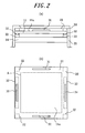
- FIG. 2 illustrates an exemplary housing structure of the input apparatus 1 illustrated in FIG. 1 ;
- FIG. 2(a) is a cross-sectional view of a main section, and
- FIG. 2(b) is a plane view of the main section.
- the display unit 14 is contained in a housing 21.
- the touch sensor 11 is disposed on the display unit 14 via insulators 22 made of elastic members.
- the display unit 14 and the touch sensor 11 are rectangular in shape in a planar view.
- the touch sensor 11 is held on the display unit 14 via the insulators 22 arranged at four corners outside a display area A of the display unit 14 illustrated by a chain double-dashed line in FIG. 2(b) .
- the housing 21 is provided with an upper cover 23 covering a surface area of the touch sensor 11 outside the display area of the display unit 14.
- An insulator 24 made of elastic member is arranged between the upper cover 23 and the touch sensor 11.
- the touch sensor 11 illustrated in FIG. 2 may have, for example, a surface member having a touch face 11a and constituted of a transparent film or the glass, and a rear face member constituted of the glass or acryl.
- the touch sensor 11 is designed such that, when the touch face 11a is pressed down, a pushed part is bent (strained) slightly in accordance with the pressing force or a structure itself is bent slightly.
- a strain gauge sensor 31 to detect the load (pressuring force) applied on the touch sensor 11 is provided, adhered or the like, on a surface of the touch sensor 11 at a position close to each periphery to be covered by the upper cover 23.
- a piezoelectric vibrator 32 to vibrate the touch sensor 11 is provided, adhered or the like, on the rear face of the touch sensor 11 at a position close to a periphery on each of two opposing sides. That is, the input apparatus illustrated in FIG. 2 has the load detection unit 12 illustrated in FIG. 1 including four strain gauge sensors 31 and the tactile sensation providing unit 13 including two piezoelectric vibrators 32. In addition, the tactile sensation providing unit 13 vibrates the touch sensor 11 such that the touch face 11a is vibrated. It is to be noted that the housing 21, the upper cover 23 and the insulator 24 illustrated in FIG. 2(a) are omitted in FIG. 2(b) .
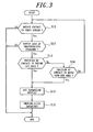
- FIG. 3 and FIG. 4 are flowcharts illustrating operations of the input apparatus 1 according to the present embodiment.
- the input apparatus 1 according to the present embodiment provides a tactile sensation when a position of a contact detected by the touch sensor 11 moves into a region corresponding to an input object while the pressure load satisfies a predetermined standard.
- the flowchart in FIG. 3 illustrates an operation to provide the tactile sensation when, after the input apparatus 1 detects a contact, the contact corresponds to key and the like or when a position of the contact moves into a position corresponding to the key and the like.
- the input objects such as the key and the like are displayed on the display unit 14 of the input apparatus 1 before receiving a contact to the touch face of the touch sensor 11.
- the input object may be a graphical image suggesting a region to receive the contact to the operator. For example, an image graphically depicting numbers and characters on key tops, as the graphical images of the input objects, is displayed on the display unit 14.
- the control unit 15 monitors a contact detected by the touch sensor 11 and a load detected by the load detection unit 12.
- the touch sensor 11 detects a contact by a pressing object (pressing means), such as the operator's finger, a stylus pen or the like
- the control unit 15 proceeds to step S12.
- the control unit 15 determines whether the pressure load detected by the load detection unit 12 is increased by a pressure on the touch sensor 11 and satisfies a predetermined standard.
- the load detection unit 12 detects the load from, for example, an average output value of the four strain gauge sensors 31.
- the Pth is preset to be, for example, 1 N (Newton) and resettable thereafter.
- the predetermined standard too low in consideration of the pressure load of the pressing input intended by the operator (for example, an average value of the pressure loads), in order to avoid receiving an inadvertent contact operation when the operator lightly touches the touch sensor 11 and also in order to provide the operator with a pressure sensation for a realistic tactile sensation described below.
- the touch sensor 11 detects a contact at step S11, the operation according to the present embodiment is not performed if the pressure load detected by the load detection unit 12 does not satisfy the predetermined standard at step S12.
- the control unit 15 determines whether a position of the contact detected by the touch sensor 11 is inside the predetermined region (step S13).
- the "predetermined region” is an area of the touch sensor 11 corresponding to a position of the display unit 14 displaying the input object such as the keys and the buttons to receive an input. Since the "predetermined region” corresponds to the key and the like, it is referred to simply as a "key region” appropriately in the following description.
- the control unit 15 changes a display state of the input object corresponding to the position of the contact detected on the display unit 14 (step S14).
- Such change of the display state of the input object at step S14 may be, for example, changing a state of the graphically depicted object such that it looks like a key depression when a mechanical push-button switch is pressed down by the operator (hereinafter, referred to as a "depression display" of the key).
- the control unit 15 drives the tactile sensation providing unit 13 with a predetermined drive signal such that the touch sensor 11 is vibrated in a predetermined vibration pattern and provides the tactile sensation (step S15).
- the tactile sensation providing unit 13 drives, for example, two piezoelectric vibrators 32 in phase.
- the input apparatus 1 receives the pressing input by a pushing operation based on an operator's intention.
- the control unit 15 determines whether the position of the contact detected by the touch sensor 11 has moved into the key region (step S16). In this case, that is, the control unit 15 determines whether the position of the contact has moved into the key region from outside the key region while the pressure load satisfies the predetermined standard. From a point of view of an operation carried out by the operator, it corresponds to an operator's motion to move (slide) the position of the contact from a position not corresponding to the input object such as the key and the like to a position corresponding thereto on the touch sensor 11 while applying the pressure load satisfying the predetermined standard to the touch sensor 11.
- step S16 When the position of the contact has not moved into the key region at step S16, the control unit 15 returns to step S 11 and determines whether the touch sensor 11 is still detecting the contact. If the touch sensor 11 does not detect the contact any longer, it may be considered that the operator has removed the finger or the like from the touch sensor 11. Therefore, the operation according to the present embodiment ends. If the touch sensor 11 is still detecting the contact, the control unit 15 performs the operation from step S12 described above.
- the control unit1 15 changes the display state of the input object corresponding to the position of the contact detected (step S14) and provides the tactile sensation (step S15).
- the control unit 15 controls drive of the tactile sensation providing unit 13 such that the tactile sensation is provided to the pressing object pressing the touch face.
- the tactile sensation provided to the pressing object by the tactile sensation providing unit 13 at step S15 is the click sensation described above.
- the input apparatus 1 stimulates a tactile sensation of the operator while stimulating a pressure sensation, by the following operation. That is, the input apparatus 1 stimulates the pressure sensation until the pressure load applied to the touch sensor 11 satisfies the standard to provide the tactile sensation (for example, 1N) and, when the pressure load satisfies the standard, stimulates the tactile sensation by driving the piezoelectric element 32 with the predetermined drive signal such that the touch face 11a is vibrated.
- the input apparatus 1 can provide the operator with the click sensation similar to that obtained when pressing the button switch such as the push-button switch (push-type button switch). Accordingly, even with the push-button switch graphically depicted on the touch sensor, the operator can carry out an input operation feeling the realistic click sensation similar to that obtained when operating the actual push-button switch. Therefore, the operator would not have a feeling of strangeness. Moreover, since the operator can carry out the input operation in conjunction with a perception to "have tapped" the touch sensor 11, erroneous inputs caused by mere tapping is prevented.
- the drive signal to provide the click sensation described above that is, a certain frequency, a period (wavelength), a waveform and a vibration amplitude to stimulate the tactile sensor may be set suitably according to the click sensation to be provided.
- the tactile sensation providing unit 13 is driven by the drive signal of, for example, a sine wave with a frequency of 170 Hz, for 1 period.
- the tactile sensation providing unit 13 is driven with the drive signal described above such that the touch face 11a is vibrated by approximately 15 ⁇ m under the standard pressure load Pth. Thereby, it is possible to provide the operator with the realistic click sensation similar to that obtained when pressing down an actual key.
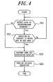
- FIG. 4 is a flowchart illustrating an operation subsequent to the operation illustrated in FIG. 3 . Since the flowchart illustrated in FIG. 4 is a sequel to the operation in FIG. 3 , it starts in a state that the touch sensor 11 detects the contact of the position corresponding to the input object displayed on the display unit 14 while the load detection unit 12 detects the pressure load satisfying the predetermined standard. That is, at start of the operation illustrated in FIG. 4 , the position of the contact is already in the key region and, simultaneously, the pressure load satisfies the predetermined standard. The flowchart illustrated in FIG. 4 is the operation performed when the position of the contact in the key region moves out of the key region.
- control unit 15 first determines whether the pressure load detected by the load detection unit 12 is still satisfying the predetermined standard (step S21).
- the control unit 15 changes the display state of the input object from the depression display to an original display therebefore and displays the input object on the display unit 14 (step S23).
- it may be considered to change the graphical image of the object from the depression display displayed at step S14 in FIG. 3 to a display representing recovery of the key from depression when pressure on the mechanical push-button switch is released.
- it is possible to display the display state such as momentarily changes the color or the brightness of the input object.
- the control unit 15 After restoring the display state of the key from the depression display at step S23, the control unit 15 drives the tactile sensation providing unit 13 with the predetermined drive signal such that the touch sensor 11 is vibrated in the predetermined vibration pattern and provides the tactile sensation (step S24).
- the control unit 15 determines whether the position of the contact detected by the touch sensor 11 has moved out of the key region (step S22). That is, in this case, the control unit 15 determines whether the position of the contact moves from inside the key region to outside the key region while the pressure load satisfies the predetermined standard. From a point of view of an operation carried out by the operator, it corresponds to an operator's motion to move (slide) the position of the contact from the position corresponding to the input object such as the key and the like to the position not corresponding thereto on the touch sensor 11 while applying the pressure load satisfying the predetermined standard to the touch sensor 11.
- control unit 15 When the position of the contact has not moved out of the key region at step S22, the control unit 15 returns to step S21 and determines whether the touch sensor 11 is still detecting the contact. When it is determined that the pressure load is no longer satisfying the predetermined standard at step S21, the control unit 15 performs operations at step S23 and step S24.
- the control unit 15 restores the display state of the input object from the depression display to the original display (step S23) and drives the tactile sensation providing unit 13 with the predetermined drive signal and provides the tactile sensation (step S24).
- the control unit 15 drives the tactile sensation providing unit 13 such that the tactile sensation is provided to the pressing object pressing the touch face.
- the tactile sensation provided to the pressing object by the tactile sensation providing unit 13 at step S24 is the release sensation described above.
- the drive signal to drive the tactile sensation providing unit 13 to provide the release sensation may be either the same as, or different from, the drive signal (for click sensation) in pressing at step S15 in FIG. 3 .
- the frequency of the drive signal (for click sensation) to provide the tactile sensation at step S15 may be at 170 Hz, while the drive signal in releasing may be at 125 Hz.
- FIG. 5 is a diagram illustrating examples of the operation and the pressure load to receive the pressing input by the input apparatus 1 according to the embodiment of the present invention.
- FIG. 5(A) is a diagram schematically illustrating a state that the operator's finger presses inside a key region ⁇ and then the pressure is released.
- the key region ⁇ is an area of the touch sensor 11 and corresponds to a position displaying the input object, such as the key and button, to receive an input on the display unit 14.
- characters such as "A" and "1" responsible for inputs and usually displayed on key tops of the input objects are omitted.
- a proportion of the key region ⁇ and the operator's finger does not reflect an actual proportion but employed for convenience sake.
- FIG. 5(B) is a graph illustrating a chronological change in the pressure load on the touch face of the touch sensor 11 detected by the load detection unit 12 during the operation illustrated in FIG. 5(A) .
- the "predetermined standard" of the pressure load set forth above is represented by Pth.
- bracketed numbers represent an order of elapsed time. In the following description, the bracketed numbers are referred to as "points" for the sake of explanation.
- a point (1) represents a state that the operator is about to press inside the key region ⁇
- a point (2) represents a state that the operator is pressing inside the key region ⁇ while applying the pressure load satisfying the predetermined standard
- a point (3) represents a state that the operator is releasing the pressure.
- the load detection unit 12 starts detecting the pressure load (that is, the operator starts pressing the touch face) between the point (1) and the point (2), and then stops detecting the pressure load (that is, the operator releases the pressure on the touch face) between the point (2) and the point (3).
- the load detection unit 12 detects the pressure load satisfying the predetermined standard Pth. The pressure load satisfies the Pth slightly before the point (2) and stops satisfying the Pth slightly after the point (2).
- the input apparatus 1 provides the click sensation when detecting the pressure load satisfying the predetermined standard Pth in the key region ⁇ and the release sensation when detecting that the pressure load stops satisfying the predetermined standard Pth in the key are ⁇ .
- a downward pointing arrow illustrated under a time axis when the pressure load satisfies the Pth slightly before the point (2) indicates when the click sensation, which is a key depression sensation, is provided.
- an upward pointing arrow illustrated under the time axis when the pressure load stops satisfying the Pth slightly after the point (2) indicates when the release sensation, a recovery sensation of key depression, is provided.
- the click sensation is provided when detecting the pressure load satisfying the predetermined standard Pth in the key region and the release sensation when the pressure load stops satisfying the predetermined standard Pth in the key region. That is, an example is above described, such that the standard of the pressure load to provide the click sensation and that to provide the release sensation have the same value Pth.
- the standard of the pressure load to provide the release sensation it is also possible to set the standard of the pressure load to provide the release sensation to be 50-80% lower than that to provide the tactile sensation in pressing.
- step S12 when the pressure load on the touch face detected satisfies the predetermined standard Pth (step S12) and the position of the contact is inside the key region ⁇ (step S13), the input apparatus 1 provides the click sensation (step S15). Similarly, even though the position of the contact is inside the key region ⁇ (START in FIG. 4 ), when the pressure load detected on the touch face stops satisfying the predetermined standard Pth (step S21), the release sensation is provided (step S24).
- the operator can obtain the click sensation when pressing the key region ⁇ while applying the pressure load satisfying the predetermined standard Pth and then obtains the release sensation when reducing the pressure load to stop satisfying the predetermined standard Pth.
- the operator can obtain the tactile sensation as it were a sensation obtained when operating the key and the like constituted of a mechanical switch.
- FIG. 6 is a diagram illustrating other examples of the operation and the pressure load to receive the pressure input by the input apparatus 1 according to the embodiment of the present invention.
- FIG. 6 and thereafter each symbol and the like has the same meaning as that described with reference to FIG. 5 .
- FIG. 6(A) is a diagram schematically illustrating a state that the operator's finger presses inside the key region ⁇ and then moves out it while the pressure load is maintained, and then the pressure is released.
- the point (1) represents a state that the operator is about to press the key region ⁇ and the point (2) represents a state that the operator is pressing inside the key region ⁇ while applying the pressure load satisfying the predetermined standard.
- the point (3) represents a state that, from the point (2), the operator is moving the position of the contact within the key region ⁇ and out therefrom while applying the pressure load satisfying the predetermined standard.
- a point (4) represents a state that, from the point (3), the operator is moving the position of the contact outside the key region ⁇ while applying the pressure load satisfying the predetermined standard.
- a point (5) represents a state that the operator is releasing the pressure.
- the load detection unit 12 starts detecting the pressure load (that is, the operator starts pressing the touch face) between the point (1) and the point (2).
- the load detection unit 12 detects the pressure load satisfying the predetermined standard Pth.
- the pressure load continuously satisfies the predetermined standard Pth (that is, the operator is moving the position of the contact while applying the pressure load satisfying the Pth).
- the load detection unit 12 continuously detects the pressure load satisfying the predetermined standard Pth (that is, the operator is moving the position of the contact while applying the pressure load satisfying the Pth).
- the pressure load stops satisfying the Pth.
- the load detection unit 12 stops detecting the pressure load (that is, the operator releases the pressure on the touch face).
- the input apparatus 1 provides the click sensation when detecting the pressure load satisfying the predetermined standard Pth in the key region ⁇ and the release sensation when the position of the contact moves out of the key region ⁇ while the pressure load satisfies the predetermined standard Pth.
- the downward pointing arrow illustrated under the time axis when the pressure load satisfies the Pth at the point (2) indicates when the click sensation is provided.
- the upward pointing arrow illustrated under the time axis at the point (3) indicates when the release sensation is provided.
- step S12 when the pressure load on the touch face detected satisfies the predetermined standard Pth (step S12) and the position of the contact is inside the key are ⁇ (step S13), the input apparatus 1 provides the click sensation (step S15).
- step S21 when the pressure load continuously satisfies the predetermined standard Pth (step S21) while the position of the contact moves out of the key region ⁇ (step S22), the input apparatus 1 provides the release sensation (step S24).
- the operator can obtain the click sensation when pressing the key region ⁇ while applying the pressure load satisfying the predetermined standard Pth and the release sensation when moving the position of the contact out of the key region ⁇ while maintaining the pressure load satisfying the predetermined standard Pth.
- the operator can obtain the tactile sensation as it were the sensation obtained when operating the key and the like constituted of the mechanical switch.
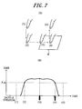
- FIG. 7 is a diagram illustrating yet other examples of the operation and the pressure load to receive the pressure input by the input apparatus 1 according to the embodiment of the present invention.
- FIG. 7(A) is a diagram schematically illustrating a state that the operator's finger presses outside the key region ⁇ , moves into the key region ⁇ while maintaining the pressure, and then the pressure is released.
- the point (1) represents the state that the operator is about to press outside the key region ⁇ and the point (2) represents the state that the operator is pressing outside the key region ⁇ while applying the pressure load satisfying the predetermined standard.
- the point (3) represents a state that, from the point (2), the operator is moving the position of the contact outside of the key region ⁇ and thereinto while applying the pressure load satisfying the predetermined standard.
- the point (4) represents a state that, from the point (3), the operator is moving the position of the contact within the key region ⁇ while applying the pressure load satisfying the predetermined standard.
- the point (5) represents a state that the operator is releasing the pressure.
- the load detection unit 12 starts detecting the pressure load (that is, the operator starts pressing the touch face) between the point (1) and the point (2).
- the load detection unit 12 detects the pressure load satisfying the predetermined standard Pth.
- the pressure load continuously satisfies the predetermined standard Pth (that is, the operator moves the position of the contact while applying the pressure load satisfying the Pth).
- the load detection unit 12 continuously detects the pressure load satisfying the predetermined standard Pth (that is, the operator moves the position of the contact while applying the pressure load satisfying the Pth).
- the pressure load stops satisfying the Pth.
- the load detection unit 12 stops detecting the pressure load (that is, the operator releases the pressure on the touch face) between the point (4) and the point (5).
- the input apparatus 1 provides the click sensation when the position of the contact moves into the key region ⁇ while the pressure load satisfies the predetermined standard Pth and the release sensation when the pressure load in the key region ⁇ detected stops satisfying the predetermined standard Pth.
- the downward pointing arrow illustrated under the time axis at the point (3) indicates when the click sensation is provided.
- the upward pointing arrow illustrated under the time axis at the point (4) when the pressure load stops satisfying the Pth indicates when the release sensation is provided.
- step S12 when the pressure load satisfies the predetermined Pth (step S12) while the position of the contact moves from outside the key region ⁇ thereinto (step S16), the input apparatus 1 provides the click sensation (step S15).
- step S21 when the position of the contact is inside the key region ⁇ (START in FIG. 4 ), when the pressure load on the touch face detected stops satisfying the predetermined standard Pth (step S21), the input apparatus 1 provides the release sensation (step S24).
- the operator it is possible for the operator to obtain the click sensation when moving the position of the contact into the key region ⁇ while maintaining the pressure load satisfying the predetermined standard Pth and the release sensation when reducing the pressure load on the key region ⁇ to stop satisfying the predetermined standard Pth.
- FIG. 8 is a diagram illustrating yet other examples of the operation and the pressure load to receive the pressure input by the input apparatus 1 according to the embodiment of the present invention.
- FIG. 8(A) is a diagram schematically illustrating a state that the operator's finger presses outside the key region ⁇ , moves into the key region ⁇ and out of the key region ⁇ while maintaining the pressure, and then the pressure is released.
- the point (1) represents the state that the operator is about to press outside the key region ⁇ and the point (2) represents the state that the operator is pressing outside the key region ⁇ while applying the pressure load satisfying the predetermined standard.
- the point (3) represents a state that, from the point (2), the operator is moving the position of the contact outside the key region ⁇ and thereinto while applying the pressure load satisfying the predetermined standard.
- the point (4) represents a state that, from the point (3), the operator is moving the position of the contact inside of the key region ⁇ and thereout while applying the pressure load satisfying the predetermined standard.
- the point (5) represents a state that, from the point (4), the operator is moving the position of the contact outside the key are ⁇ while applying the pressure load satisfying the predetermined standard.
- the point (6) represents a state that the operator is releasing the pressure.
- the load detection unit 12 starts detecting the pressure load (that is, the operator starts pressing the touch face) between the point (1) and the point (2).
- the load detection unit 12 detects the pressure load satisfying the predetermined standard Pth.
- the pressure load continuously satisfies the predetermined standard Pth (that is, the operator moves the position of the contact while applying the pressure load satisfying the Pth).
- the load detection unit 12 continuously detects the pressure load satisfying the predetermined standard Pth (that is, the operator moves the position of the contact while applying the pressure load satisfying the Pth).
- the pressure load stops satisfying the Pth.
- the load detection unit 12 stops detecting the pressure load (that is, the operator releases the pressure on the touch face) between the point (5) and the point (6).
- the input apparatus 1 provides the click sensation when the position of the contact moves into the key region ⁇ while the pressure load satisfies the predetermined standard Pth.
- the input apparatus 1 provides the release sensation when the position of the contact moves out of the key region ⁇ while the pressure load satisfies the predetermined standard Pth.
- the downward pointing arrow illustrated under the time axis at the point (3) indicates when the click sensation is provided.
- the upward pointing arrow illustrated under the time axis at the point (4) indicates when the release sensation is provided.
- step S12 when the pressure load satisfies the predetermined Pth (step S12) while the position of the contact moves into the key region ⁇ (step S16), the input apparatus 1 provides the click sensation (step S15).
- step S21 when the pressure load satisfies the predetermined standard Pth (step S21) while the position of the contact moves out of the key region ⁇ (step S22), the input apparatus 1 provides the release sensation (step S24).
- the operator can obtain the click sensation when moving the position of the contact into the key region ⁇ while maintaining the pressure load satisfying the predetermined standard Pth and then the release sensation when moving the position of the contact out of the key region ⁇ while maintaining the pressure load satisfying the predetermined standard Pth.
- FIG. 9 is a diagram illustrating yet other examples of the operation and the pressure load to receive the pressure input by the input apparatus 1 according to the embodiment of the present invention.
- FIG. 9(A) is a diagram schematically illustrating a state that the operator's finger presses outside the key region ⁇ , moves into the key region ⁇ and then out of the key region ⁇ while maintaining the pressure, moves into a key region ⁇ and then out of the key region ⁇ while maintaining the pressure, and releases the pressure. Even when the position of the contact moves across a plurality of different key regions, the input apparatus 1 performs the same operation as described above.
- the point (1) represents the state that the operator is about to press outside the key region ⁇ and the point (2) represents the state that the operator is pressing outside the key region ⁇ while applying the pressure load satisfying the predetermined standard.
- the point (3) represents a state that, from the point (2), the operator is moving the position of the contact outside the key region ⁇ and thereinto while applying the pressure load satisfying the predetermined standard.
- the point (4) represents a state that, from the point (3), the operator is moving the position of the contact inside the key region ⁇ and thereout while applying the pressure load satisfying the predetermined standard.
- the point (5) represents a state that, from the point (4), the operator is moving the position of the contact into the key region ⁇ from outside the key region ⁇ or ⁇ while applying the pressure load satisfying the predetermined standard.
- the point (6) represents a state that, from the point (5), the operator is moving the position of the contact inside the key region ⁇ and thereout while applying the pressure load satisfying the predetermined standard.
- the point (7) represents a state that, from the point (6), the operator is moving the position of the contact outside the key region ⁇ while applying the pressure load satisfying the predetermined standard.
- the point (8) represents the state that the operator is releasing the pressure.
- the input apparatus 1 Based on this operation, as illustrated in FIG. 9(B) , the input apparatus 1 provides the click sensation at the point (3) and the release sensation at the point (4). Further, the input apparatus 1 provides the click sensation again at the point (5) and the release sensation again at the point (6). At the point (2), although the pressure load satisfies the Pth, the input apparatus 1 does not provide the tactile sensation. At the point (7), in addition, although the pressure load stops satisfying the Pth, the input apparatus 1 does not provide the tactile sensation.
- the operator can obtain the click sensation when moving the position of the contact into the key region ⁇ or the key region ⁇ while maintaining the pressure load satisfying the predetermined standard Pth.
- the operator can obtain the release sensation when moving the position of the contact out of the key region ⁇ or the key region ⁇ while maintaining the pressure load satisfying the predetermined standard Pth.
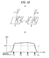
- FIG. 10 is a diagram illustrating yet other examples of the operation and the pressure load to receive the pressure input by the input apparatus 1 according to the embodiment of the present invention.
- FIG. 10(A) is a diagram schematically illustrating a state that the operator's finger presses inside the key region ⁇ , moves out of the key region ⁇ and into the key region ⁇ while maintaining the pressure, and then the pressure is released. Even when the position of the contact moves between a plurality of different key regions, the input apparatus 1 performs the same operation as described above.
- the point (1) represents the state that the operator is about to press inside the key region ⁇ and the point (2) represents the state that the operator is pressing inside the key region ⁇ while applying the pressure load satisfying the predetermined standard.
- the point (3) represents a state that, from the point (2), the operator is moving the position of the contact inside the key region ⁇ and thereout while applying the pressure load satisfying the predetermined standard.
- the point (4) represents a state that, from the point (3), the operator is moving the position of the contact outside the key regions ⁇ or ⁇ and into the key region ⁇ , while applying pressure load satisfying the predetermined standard.
- the point (5) represents a state that, from the point (4), the operator is moving the position of the contact within the key region ⁇ while applying the pressure load satisfying the predetermined standard.
- the point (6) represents the state that the operator is releasing the pressure.
- the input apparatus 1 Based on the operation described above, as illustrated in FIG. 10(B) , the input apparatus 1 provides the click sensation at the point (2) and the release sensation at the point (3). Further, the input apparatus 1 provides the click sensation again at the point (4) and the release sensation again at the point (5).
- the operator can obtain the click sensation when pressing inside the key region ⁇ or the key region ⁇ while applying the pressure load satisfying the predetermined standard Pth and the release sensation when reducing the pressure load inside the key region ⁇ or the key region ⁇ such that the pressure load stops satisfying the predetermined standard Pth.
- the operator can obtain the click sensation when moving the position of the contact into the key region ⁇ or the key region ⁇ while applying the pressure load satisfying the predetermined standard Pth.
- the operator can obtain the release sensation when moving the position of the contact out of the key region ⁇ or the key region ⁇ while applying the pressure load satisfying the predetermined standard Pth.
- the present invention is not limited to the above embodiment but may be modified or varied in a multiple of manners.
- it is possible to appropriately generate a sound in conjunction with the operation in addition to the operation in each of the above embodiments. Thereby, it facilitates operator's recognition, further improving operability of the input apparatus and reducing generation of erroneous inputs.
- the touch face of the touch sensor has one or two key regions for the sake of simplification in the embodiment set forth above, it is appreciated that three or more key regions can be provided.
- in inputting the operator moves the position of the contact in a crosswise direction for the sake of simplification.
- it is appreciated that it is also possible to move the position of the contact in any directions including a longitude direction.
- the load detection unit in the above embodiment may be constituted by using any number of strain gauge sensors.
- the load detection unit may be constituted according to a contact detection scheme of the touch sensor.
- the load detection unit can be constituted without using the strain gauge sensor if the load can be detected from a change of an output signal based on a resistance change in accordance with a contact region in using the resistive film type.
- the load detection unit can be constituted without using the strain gauge sensor if the load can be detected from a change in an output signal based on a change in capacitance in using the capacitive type.
- the tactile sensation providing unit may be constituted by using any number of piezoelectric transducers, transparent piezoelectric elements provided on an entire operation surface of the touch sensor or, if it is possible to vibrate such that the tactile sensation is provided, an eccentric motor which rotates 360 degrees in 1 cycle of the drive signal.
- the tactile sensation providing unit is driven when the pressure load detected by the load detection unit satisfies the predetermined standard to provide the tactile sensation.
- This "when the pressure load detected by the load detection unit satisfies the standard” may represent “when the pressure load detected by the load detection unit reaches a standard value to provide the tactile sensation", “when the pressure load detected by the load detection unit exceeds the standard value to provide the tactile sensation", or "when the standard value to provide the tactile sensation is detected by the load detection unit”.
Landscapes
- Engineering & Computer Science (AREA)
- General Engineering & Computer Science (AREA)
- Theoretical Computer Science (AREA)
- Human Computer Interaction (AREA)
- Physics & Mathematics (AREA)
- General Physics & Mathematics (AREA)
- Position Input By Displaying (AREA)
- User Interface Of Digital Computer (AREA)
Description
- This application claims priority of Japanese Patent Application No.
2009-197318 filed on August 27, 2009 - The present invention relates to an input apparatus having a touch sensor.
- In recent years, there are mobile terminals such as mobile phones that employ input apparatuses having touch sensors such as touch panels, touch switches, or the like, as input apparatuses such as operation units, switches and the like configured to receive input operations by users. Such input apparatuses having touch sensors are popularly employed not only by the mobile terminals but also by information equipments such as calculators, ticket vending machines, home electric appliances such as microwaves, TV sets, lighting equipments, industrial equipments (FA equipments) and the like.
- There are known a variety of types of those touch sensors, such as a resistive film type, a capacitive type, an optical type and the like. However, touch sensors of any of these types receive a touch input by a finger or a stylus pen, and, unlike push-button switches, touch sensors themselves are not physically displaced when touched.
- Since the touch sensors themselves are not physically displaced when touched, an operator cannot obtain feedback to an input even though the touch input is received. As an operation feeling to "have pressed or have canceled pressing down" is not obtained in operation input, the operator cannot perceive whether the touch sensor detects the operation input. As a result, the operator is likely to repeat inputting the same spot multiple times, which may be stressful for the operator.
- In order to prevent such unnecessary repetitive inputs, there are known input apparatuses allowing for visual or auditory confirmation of the input operations by, for example, generating sounds when detecting the touch input or by changing a display state, such as colors of input objects such as input buttons and the like graphically depicted on a display unit, based on an input position.
- However, such auditory feedback may be difficult to be confirmed in a noisy environment and is not applicable when the equipment being used is in a silent mode.
- In addition, in using such visual feedback, if the input object displayed on the display unit is small, the operator may not be able to confirm the change in the display state, as a view of the input object is blocked by a finger, particularly when the operator is inputting by the finger.
- In order to deal with such a problem, there is also suggested a feedback method relying on neither the auditory- nor visual sensation but instead generating a tactile sensation at operator's fingertip by vibrating the touch sensor when the touch sensor detects an input (for example, see
Patent Documents 1,2). - Document
US 2002/0149561 A1 discloses an electronic device which drives an oscillatory actuator to cause generation of vibration when it is detected that an operation input to a touch panel has been received. A particular waveform is used to drive an oscillatory actuator if an icon is dragged onto a trash icon. -
- Patent Document 1: Japanese Patent Laid-Open No.
2003-288158 - Patent Document 2: Japanese Patent Laid-Open No.
2008-130055 - According to the techniques disclosed in the
above Patent Documents - In addition, application of such technique to the input apparatus enables to provide the tactile sensation only when there is an input to the touch sensor at a position corresponding to the input object such as the input button and the like graphically depicted on the display unit, based on position information from the touch sensor. That is, the input apparatus adopting the technique described above, while displaying the input objects such as keys and buttons on the display unit, is capable of providing the tactile sensation not in response to the touch input to the touch sensor at a position corresponding to no keys but in response to the touch input to the touch sensor at a position corresponding to the key.
- The techniques disclosed in the
above Patent Documents - Incidentally, there is a so-called slide input as an input method which is characteristic in an input mode using the touch sensor. The slide input is an input to move a touch position while maintaining a light contact (touch) to the touch face of the touch sensor, which is similar to an operation to lightly drag the finger or the like on the touch face.
- It causes a problem when the input apparatus with the touch sensor adopting conventional schemes described above provides the tactile sensation as it were a sensation obtained when operating the mechanical push-button switch. More specifically, for example, when the touch sensor detects the slide input from a position corresponding to no keys to a position corresponding to the key, this input apparatus considers that the key is pressed down and provides the tactile sensation. Since the tactile sensation is provided even though the operator lightly dragged the fingers or like without pushing the button switch graphically depicted as the object, it results in an operation bringing the feeling of strangeness to the operator.
- In operating the mechanical push-button switch, the operator should expect that a tactile sensation of depression of the switch (hereinafter, referred to as a click sensation) is provided when the operator moves a pressing position from a position with no switch to a position with a switch while applying a certain pressure. Similarly, in operating the mechanical push-button switch, the operator expects that another tactile sensation of recovery of the pressed switch to an original unpressed state (hereinafter, referred to as a release sensation) is provided when the operator moves the pressing position from the position with the switch to the position with no switch while applying the certain pressure. Moreover, in operating the mechanical push-button switch, the operator expects that neither the click sensation nor the release sensation is provided when the operator moves the pressing position from the position with no switch to the position with the switch, and vice versa, while applying a very light pressure.
- The conventional input apparatuses described above, however, determine whether to provide the tactile sensation based on the position information from the touch sensor in response to the slide input on the touch sensor and uniformly provide the tactile sensation regardless of strength of the pressure of the slide input. Accordingly, even when the operator drags the fingers or the like on the touch sensor applying a very light pressure without an intention to push it, such motion is detected as the slide input. If this slide input is carried out at a position corresponding to the input object, it is considered that the key is pressed down and the tactile sensation is provided. Therefore, the operator has the feeling of strangeness in operation due to the tactile sensation unexpectedly provided. In such a case, moreover, an operation based on the user's unintended input is executed, which imposes an extra operation to cancel the operation or to re-input on the operator.
- Accordingly, an object of the present invention in consideration of such conditions is to provide an input apparatus capable of providing, through the touch sensor, the tactile sensation as it were a sensation obtained when operating the key and the like constituted of a mechanical switch.
- In order to achieve the above object, an input apparatus according to a first aspect of the present invention includes:
- a touch sensor configured to detect a contact, the touch sensor having a touch face,
- a tactile sensation providing unit configured to vibrate the touch face;
- a load detection unit configured to detect a pressure load on the touch face of the touch sensor; and
- a control unit configured to control drive of the tactile sensation providing unit, when a position of the contact detected by the touch sensor moves into or out of a predetermined region while the pressure load detected by the load detection unit satisfies a predetermined standard for receiving an input operation to the predetermined region, such that a tactile sensation is provided to an object pressing the touch face.
- According to the present invention, when the position of the contact to the touch sensor moves into the predetermined region while the pressure load satisfies the standard load, the tactile sensation is provided to the object pressing the touch face. According to the present invention, therefore, it is possible to provide, through the touch sensor, the tactile sensation as it were a sensation obtained when operating the key and the like constituted of a mechanical switch. Thereby, it is possible for the operator to feel a realistic sensation, such as one obtained when operating a mechanical push-button switch, without a feeling of strangeness. In addition, since an operation based on an unintentional input by the operator is avoided, the burden of re-inputting and the like for the operator is eliminated.
-
-
FIG. 1 is a block diagram illustrating a schematic constitution of an input apparatus according to an embodiment of the present invention; -
FIG. 2 illustrates an exemplary housing structure of the input apparatus according to the embodiment of the present invention; -
FIG. 3 is a flowchart illustrating an operation by the input apparatus according to the embodiment of the present invention when a position of a contact moves into a key region; -
FIG. 4 is a flowchart illustrating an operation by the input apparatus according to the embodiment of the present invention when the position of the contact moves out of the key region; -
FIG. 5 illustrates examples of an operation and a pressure load received by the input apparatus according to the embodiment of the present invention; -
FIG. 6 illustrates other examples of the operation and the pressure load received by the input apparatus according to the embodiment of the present invention; -
FIG. 7 illustrates yet other examples of the operation and the pressure load received by the input apparatus according to the embodiment of the present invention; -
FIG. 8 illustrates yet other examples of the operation and the pressure load received by the input apparatus according to the embodiment of the present invention; -
FIG. 9 illustrates yet other examples of the operation and the pressure load received by the input apparatus according to the embodiment of the present invention; and -
FIG. 10 illustrates yet other examples of the operation and the pressure load received by the input apparatus according to the embodiment of the present invention. - An embodiment of the present invention will be described with reference to the accompanying drawings.
-
FIG. 1 is a block diagram illustrating a schematic constitution of an input apparatus according to an embodiment of the present invention. According to the present embodiment, any input apparatus is applicable, as long as it receives an operator's touch input by using a touch sensor. Such input apparatuses may be mounted on, for example, mobile terminals used to input characters and numbers, ATM machines at a bank, and ticket vending machines at a train station. - As illustrated in
FIG. 1 , aninput apparatus 1 according to the present embodiment has atouch sensor 11, aload detection unit 12, a tactilesensation providing unit 13, adisplay unit 14, and acontrol unit 15 configured to control overall operations. - The
touch sensor 11 is usually disposed on a front face of thedisplay unit 14 such that a touch face of thetouch sensor 11 detects a pressing input (contact) to a key and a button (hereinafter, referred to simply as a "key and the like") displayed on thedisplay unit 14 by an operator's finger or the like. Thetouch sensor 11 may be configured, for example, by a known type such as a resistive film type, a capacitive type, an optical type or the like. Theload detection unit 12 detects a pressure load applied to the touch face of thetouch sensor 11 and may include an element such as, for example, a strain gauge sensor, a piezoelectric element or the like, which linearly reacts to a load. The tactilesensation providing unit 13 vibrates thetouch sensor 11 and may include, for example, a piezoelectric vibrator. Thedisplay unit 14 displays an input object of an input button and the like such as a push-button switch (push-type button switch) and may include, for example, a liquid crystal display panel, an organic EL display panel or the like. -
FIG. 2 illustrates an exemplary housing structure of theinput apparatus 1 illustrated inFIG. 1 ;FIG. 2(a) is a cross-sectional view of a main section, andFIG. 2(b) is a plane view of the main section. Thedisplay unit 14 is contained in ahousing 21. Thetouch sensor 11 is disposed on thedisplay unit 14 viainsulators 22 made of elastic members. In theinput apparatus 1 according to the present embodiment, thedisplay unit 14 and thetouch sensor 11 are rectangular in shape in a planar view. Also, according to the present embodiment, thetouch sensor 11 is held on thedisplay unit 14 via theinsulators 22 arranged at four corners outside a display area A of thedisplay unit 14 illustrated by a chain double-dashed line inFIG. 2(b) . - The
housing 21 is provided with anupper cover 23 covering a surface area of thetouch sensor 11 outside the display area of thedisplay unit 14. Aninsulator 24 made of elastic member is arranged between theupper cover 23 and thetouch sensor 11. - The
touch sensor 11 illustrated inFIG. 2 may have, for example, a surface member having atouch face 11a and constituted of a transparent film or the glass, and a rear face member constituted of the glass or acryl. Thetouch sensor 11 is designed such that, when thetouch face 11a is pressed down, a pushed part is bent (strained) slightly in accordance with the pressing force or a structure itself is bent slightly. - A
strain gauge sensor 31 to detect the load (pressuring force) applied on thetouch sensor 11 is provided, adhered or the like, on a surface of thetouch sensor 11 at a position close to each periphery to be covered by theupper cover 23. In addition, apiezoelectric vibrator 32 to vibrate thetouch sensor 11 is provided, adhered or the like, on the rear face of thetouch sensor 11 at a position close to a periphery on each of two opposing sides. That is, the input apparatus illustrated inFIG. 2 has theload detection unit 12 illustrated inFIG. 1 including fourstrain gauge sensors 31 and the tactilesensation providing unit 13 including twopiezoelectric vibrators 32. In addition, the tactilesensation providing unit 13 vibrates thetouch sensor 11 such that thetouch face 11a is vibrated. It is to be noted that thehousing 21, theupper cover 23 and theinsulator 24 illustrated inFIG. 2(a) are omitted inFIG. 2(b) . -
FIG. 3 andFIG. 4 are flowcharts illustrating operations of theinput apparatus 1 according to the present embodiment. Theinput apparatus 1 according to the present embodiment provides a tactile sensation when a position of a contact detected by thetouch sensor 11 moves into a region corresponding to an input object while the pressure load satisfies a predetermined standard. - The flowchart in
FIG. 3 illustrates an operation to provide the tactile sensation when, after theinput apparatus 1 detects a contact, the contact corresponds to key and the like or when a position of the contact moves into a position corresponding to the key and the like. In order to start the operation illustrated in the flowchart inFIG. 3 , the input objects such as the key and the like are displayed on thedisplay unit 14 of theinput apparatus 1 before receiving a contact to the touch face of thetouch sensor 11. According to the present embodiment, the input object may be a graphical image suggesting a region to receive the contact to the operator. For example, an image graphically depicting numbers and characters on key tops, as the graphical images of the input objects, is displayed on thedisplay unit 14. - When the
input apparatus 1 according to the present embodiment starts the operation, thecontrol unit 15 monitors a contact detected by thetouch sensor 11 and a load detected by theload detection unit 12. At step S11, when thetouch sensor 11 detects a contact by a pressing object (pressing means), such as the operator's finger, a stylus pen or the like, thecontrol unit 15 proceeds to step S12. - At step S12, the
control unit 15 determines whether the pressure load detected by theload detection unit 12 is increased by a pressure on thetouch sensor 11 and satisfies a predetermined standard. Theload detection unit 12 detects the load from, for example, an average output value of the fourstrain gauge sensors 31. Here, it is preferable that, based on the pressure load of a usual pressing operation by the operator, the Pth is preset to be, for example, 1 N (Newton) and resettable thereafter. In addition, it is avoided to set the predetermined standard too low in consideration of the pressure load of the pressing input intended by the operator (for example, an average value of the pressure loads), in order to avoid receiving an inadvertent contact operation when the operator lightly touches thetouch sensor 11 and also in order to provide the operator with a pressure sensation for a realistic tactile sensation described below. Even though thetouch sensor 11 detects a contact at step S11, the operation according to the present embodiment is not performed if the pressure load detected by theload detection unit 12 does not satisfy the predetermined standard at step S12. - When the pressure load satisfying the predetermined standard is detected at step S12, the
control unit 15 determines whether a position of the contact detected by thetouch sensor 11 is inside the predetermined region (step S13). According to the present embodiment, the "predetermined region" is an area of thetouch sensor 11 corresponding to a position of thedisplay unit 14 displaying the input object such as the keys and the buttons to receive an input. Since the "predetermined region" corresponds to the key and the like, it is referred to simply as a "key region" appropriately in the following description. - If the position of the contact is inside the key region at step S13, the
control unit 15 changes a display state of the input object corresponding to the position of the contact detected on the display unit 14 (step S14). Such change of the display state of the input object at step S14 may be, for example, changing a state of the graphically depicted object such that it looks like a key depression when a mechanical push-button switch is pressed down by the operator (hereinafter, referred to as a "depression display" of the key). Alternatively, it is also possible to change the display state of the input object by momentarily changing color or brightness of the input object, in order to clearly notify reception of the pressing input by the operator. - After the depression display of the key at step S14, the
control unit 15 drives the tactilesensation providing unit 13 with a predetermined drive signal such that thetouch sensor 11 is vibrated in a predetermined vibration pattern and provides the tactile sensation (step S15). The tactilesensation providing unit 13 drives, for example, twopiezoelectric vibrators 32 in phase. As described above, theinput apparatus 1 receives the pressing input by a pushing operation based on an operator's intention. - On the other hand, if the position of the contact is outside the key region at step S13, the
control unit 15 determines whether the position of the contact detected by thetouch sensor 11 has moved into the key region (step S16). In this case, that is, thecontrol unit 15 determines whether the position of the contact has moved into the key region from outside the key region while the pressure load satisfies the predetermined standard. From a point of view of an operation carried out by the operator, it corresponds to an operator's motion to move (slide) the position of the contact from a position not corresponding to the input object such as the key and the like to a position corresponding thereto on thetouch sensor 11 while applying the pressure load satisfying the predetermined standard to thetouch sensor 11. - When the position of the contact has not moved into the key region at step S16, the
control unit 15 returns to stepS 11 and determines whether thetouch sensor 11 is still detecting the contact. If thetouch sensor 11 does not detect the contact any longer, it may be considered that the operator has removed the finger or the like from thetouch sensor 11. Therefore, the operation according to the present embodiment ends. If thetouch sensor 11 is still detecting the contact, thecontrol unit 15 performs the operation from step S12 described above. - On the other hand, if the position of the contact moves into the key region at step S16, the control unit1 15 changes the display state of the input object corresponding to the position of the contact detected (step S14) and provides the tactile sensation (step S15). Here, when the position of the contact detected by the
touch sensor 11 moves into the predetermined region while the pressure load detected by theload detection unit 12 satisfies the predetermined standard, thecontrol unit 15 controls drive of the tactilesensation providing unit 13 such that the tactile sensation is provided to the pressing object pressing the touch face. - Preferably, the tactile sensation provided to the pressing object by the tactile
sensation providing unit 13 at step S15 is the click sensation described above. In order to provide a realistic click sensation to the operator, theinput apparatus 1 stimulates a tactile sensation of the operator while stimulating a pressure sensation, by the following operation. That is, theinput apparatus 1 stimulates the pressure sensation until the pressure load applied to thetouch sensor 11 satisfies the standard to provide the tactile sensation (for example, 1N) and, when the pressure load satisfies the standard, stimulates the tactile sensation by driving thepiezoelectric element 32 with the predetermined drive signal such that thetouch face 11a is vibrated. Thereby, theinput apparatus 1 can provide the operator with the click sensation similar to that obtained when pressing the button switch such as the push-button switch (push-type button switch). Accordingly, even with the push-button switch graphically depicted on the touch sensor, the operator can carry out an input operation feeling the realistic click sensation similar to that obtained when operating the actual push-button switch. Therefore, the operator would not have a feeling of strangeness. Moreover, since the operator can carry out the input operation in conjunction with a perception to "have tapped" thetouch sensor 11, erroneous inputs caused by mere tapping is prevented. - The drive signal to provide the click sensation described above, that is, a certain frequency, a period (wavelength), a waveform and a vibration amplitude to stimulate the tactile sensor may be set suitably according to the click sensation to be provided. For example, in order to provide the click sensation represented by a metal dome switch employed by the mobile terminal, the tactile
sensation providing unit 13 is driven by the drive signal of, for example, a sine wave with a frequency of 170 Hz, for 1 period. The tactilesensation providing unit 13 is driven with the drive signal described above such that thetouch face 11a is vibrated by approximately 15 µm under the standard pressure load Pth. Thereby, it is possible to provide the operator with the realistic click sensation similar to that obtained when pressing down an actual key. -
FIG. 4 is a flowchart illustrating an operation subsequent to the operation illustrated inFIG. 3 . Since the flowchart illustrated inFIG. 4 is a sequel to the operation inFIG. 3 , it starts in a state that thetouch sensor 11 detects the contact of the position corresponding to the input object displayed on thedisplay unit 14 while theload detection unit 12 detects the pressure load satisfying the predetermined standard. That is, at start of the operation illustrated inFIG. 4 , the position of the contact is already in the key region and, simultaneously, the pressure load satisfies the predetermined standard. The flowchart illustrated inFIG. 4 is the operation performed when the position of the contact in the key region moves out of the key region. - When the operation of the
input apparatus 1 illustrated by the flowchart inFIG. 4 is started, thecontrol unit 15 first determines whether the pressure load detected by theload detection unit 12 is still satisfying the predetermined standard (step S21). - When it is determined that the pressure load is no longer satisfying the predetermined standard at step S21, the
control unit 15 changes the display state of the input object from the depression display to an original display therebefore and displays the input object on the display unit 14 (step S23). In restoring the display state of the input object at step S23, it may be considered to change the graphical image of the object from the depression display displayed at step S14 inFIG. 3 to a display representing recovery of the key from depression when pressure on the mechanical push-button switch is released. In this case also, in order to clearly notify that it has stopped receiving the pressing input by the operator, that is, the pressing input is canceled, it is possible to display the display state such as momentarily changes the color or the brightness of the input object. - After restoring the display state of the key from the depression display at step S23, the
control unit 15 drives the tactilesensation providing unit 13 with the predetermined drive signal such that thetouch sensor 11 is vibrated in the predetermined vibration pattern and provides the tactile sensation (step S24). - On the other hand, when it is determined that the pressure load is still satisfying the predetermined standard at step S21, the
control unit 15 determines whether the position of the contact detected by thetouch sensor 11 has moved out of the key region (step S22). That is, in this case, thecontrol unit 15 determines whether the position of the contact moves from inside the key region to outside the key region while the pressure load satisfies the predetermined standard. From a point of view of an operation carried out by the operator, it corresponds to an operator's motion to move (slide) the position of the contact from the position corresponding to the input object such as the key and the like to the position not corresponding thereto on thetouch sensor 11 while applying the pressure load satisfying the predetermined standard to thetouch sensor 11. - When the position of the contact has not moved out of the key region at step S22, the
control unit 15 returns to step S21 and determines whether thetouch sensor 11 is still detecting the contact. When it is determined that the pressure load is no longer satisfying the predetermined standard at step S21, thecontrol unit 15 performs operations at step S23 and step S24. - On the other hand, when the position of the contact moves out of the key region at step S22, the
control unit 15 restores the display state of the input object from the depression display to the original display (step S23) and drives the tactilesensation providing unit 13 with the predetermined drive signal and provides the tactile sensation (step S24). Here, that is, when the position of the contact detected by thetouch sensor 11 moves out of the predetermined region while the pressure load detected by theload detection unit 12 satisfies the predetermined standard, thecontrol unit 15 drives the tactilesensation providing unit 13 such that the tactile sensation is provided to the pressing object pressing the touch face. - Preferably, the tactile sensation provided to the pressing object by the tactile
sensation providing unit 13 at step S24 is the release sensation described above. The drive signal to drive the tactilesensation providing unit 13 to provide the release sensation may be either the same as, or different from, the drive signal (for click sensation) in pressing at step S15 inFIG. 3 . For example, the frequency of the drive signal (for click sensation) to provide the tactile sensation at step S15 may be at 170 Hz, while the drive signal in releasing may be at 125 Hz. Thereby, it is possible to provide the operator with the realistic release sensation, different from the click sensation, obtained when releasing the actual key. As stated above, it is possible to provide the release sensation in releasing after the click sensation by pressing is provided, as a counterpart of the click sensation, by driving the tactilesensation providing unit 13 with the predetermined drive signal and vibrating thetouch sensor 11 in the predetermined vibration pattern in the same manner as that in pressing. Accordingly, in combination with the click sensation in pressing, it is possible to provide the operator with the click sensation more similar to that of the push-button switch. - With reference to
FIG. 5 to FIG. 10 , an example of the operation by theinput apparatus 1 according to the present embodiment described with reference toFIG. 3 andFIG. 4 will be described below.FIG. 5 is a diagram illustrating examples of the operation and the pressure load to receive the pressing input by theinput apparatus 1 according to the embodiment of the present invention. -
FIG. 5(A) is a diagram schematically illustrating a state that the operator's finger presses inside a key region α and then the pressure is released. InFIG. 5(A) , the key region α is an area of thetouch sensor 11 and corresponds to a position displaying the input object, such as the key and button, to receive an input on thedisplay unit 14. InFIG. 5(A) , characters such as "A" and "1" responsible for inputs and usually displayed on key tops of the input objects are omitted. In addition, a proportion of the key region α and the operator's finger does not reflect an actual proportion but employed for convenience sake. -
FIG. 5(B) is a graph illustrating a chronological change in the pressure load on the touch face of thetouch sensor 11 detected by theload detection unit 12 during the operation illustrated inFIG. 5(A) . InFIG. 5(B) , the "predetermined standard" of the pressure load set forth above is represented by Pth. In addition, bracketed numbers represent an order of elapsed time. In the following description, the bracketed numbers are referred to as "points" for the sake of explanation. - As illustrated in
FIG. 5(A) , a point (1) represents a state that the operator is about to press inside the key region α, a point (2) represents a state that the operator is pressing inside the key region α while applying the pressure load satisfying the predetermined standard, and a point (3) represents a state that the operator is releasing the pressure. In such an operation, as illustrated inFIG. 5(B) , theload detection unit 12 starts detecting the pressure load (that is, the operator starts pressing the touch face) between the point (1) and the point (2), and then stops detecting the pressure load (that is, the operator releases the pressure on the touch face) between the point (2) and the point (3). At the point (2), in addition, theload detection unit 12 detects the pressure load satisfying the predetermined standard Pth. The pressure load satisfies the Pth slightly before the point (2) and stops satisfying the Pth slightly after the point (2). - As described with reference to
FIG. (3 ) andFIG. (4 ), theinput apparatus 1 according to the present embodiment provides the click sensation when detecting the pressure load satisfying the predetermined standard Pth in the key region α and the release sensation when detecting that the pressure load stops satisfying the predetermined standard Pth in the key are α. InFIG. 5(B) , a downward pointing arrow illustrated under a time axis when the pressure load satisfies the Pth slightly before the point (2) indicates when the click sensation, which is a key depression sensation, is provided. Similarly, an upward pointing arrow illustrated under the time axis when the pressure load stops satisfying the Pth slightly after the point (2) indicates when the release sensation, a recovery sensation of key depression, is provided. - According to the present embodiment, the click sensation is provided when detecting the pressure load satisfying the predetermined standard Pth in the key region and the release sensation when the pressure load stops satisfying the predetermined standard Pth in the key region. That is, an example is above described, such that the standard of the pressure load to provide the click sensation and that to provide the release sensation have the same value Pth. However, it is also possible to set the standard of the pressure load to provide the release sensation to be 50-80% lower than that to provide the tactile sensation in pressing. Thereby, when the operator clicks and then releases the pressure at the same position (input object), a sequential operation to press and release the pressure and timings to provide the tactile sensations become in synchronization with one another spontaneously, providing realistic click sensation and release sensation without the feeling of strangeness.
- As described above, when the pressure load on the touch face detected satisfies the predetermined standard Pth (step S12) and the position of the contact is inside the key region α (step S13), the
input apparatus 1 provides the click sensation (step S15). Similarly, even though the position of the contact is inside the key region α (START inFIG. 4 ), when the pressure load detected on the touch face stops satisfying the predetermined standard Pth (step S21), the release sensation is provided (step S24). - According to the
input apparatus 1 of the embodiment of the present invention, as described above, the operator can obtain the click sensation when pressing the key region α while applying the pressure load satisfying the predetermined standard Pth and then obtains the release sensation when reducing the pressure load to stop satisfying the predetermined standard Pth. Thereby, the operator can obtain the tactile sensation as it were a sensation obtained when operating the key and the like constituted of a mechanical switch. -
FIG. 6 is a diagram illustrating other examples of the operation and the pressure load to receive the pressure input by theinput apparatus 1 according to the embodiment of the present invention. InFIG. 6 and thereafter, each symbol and the like has the same meaning as that described with reference toFIG. 5 .FIG. 6(A) is a diagram schematically illustrating a state that the operator's finger presses inside the key region α and then moves out it while the pressure load is maintained, and then the pressure is released. - As illustrated in
FIG. 6(A) , the point (1) represents a state that the operator is about to press the key region α and the point (2) represents a state that the operator is pressing inside the key region α while applying the pressure load satisfying the predetermined standard. The point (3) represents a state that, from the point (2), the operator is moving the position of the contact within the key region α and out therefrom while applying the pressure load satisfying the predetermined standard. A point (4) represents a state that, from the point (3), the operator is moving the position of the contact outside the key region α while applying the pressure load satisfying the predetermined standard. A point (5) represents a state that the operator is releasing the pressure. - In this operation, as illustrated in
FIG. 6(B) , theload detection unit 12 starts detecting the pressure load (that is, the operator starts pressing the touch face) between the point (1) and the point (2). At the point (2), theload detection unit 12 detects the pressure load satisfying the predetermined standard Pth. Between the point (2) and the point (3), the pressure load continuously satisfies the predetermined standard Pth (that is, the operator is moving the position of the contact while applying the pressure load satisfying the Pth). Between the point (3) and the point (4) also, theload detection unit 12 continuously detects the pressure load satisfying the predetermined standard Pth (that is, the operator is moving the position of the contact while applying the pressure load satisfying the Pth). At the point (4), the pressure load stops satisfying the Pth. Then, between the point (4) and the point (5), theload detection unit 12 stops detecting the pressure load (that is, the operator releases the pressure on the touch face). - As described with reference to
FIG. 3 andFIG. 4 , theinput apparatus 1 according to the present embodiment provides the click sensation when detecting the pressure load satisfying the predetermined standard Pth in the key region α and the release sensation when the position of the contact moves out of the key region α while the pressure load satisfies the predetermined standard Pth. - As illustrated in
FIG. 6(B) , the downward pointing arrow illustrated under the time axis when the pressure load satisfies the Pth at the point (2) indicates when the click sensation is provided. Similarly, the upward pointing arrow illustrated under the time axis at the point (3) indicates when the release sensation is provided. Although the pressure load stops satisfying the Pth at the point (4), neither a condition to provide the click sensation nor that to provide the release sensation is not satisfied. Therefore, theinput apparatus 1 does not provide the tactile sensation at this point. - As described above, when the pressure load on the touch face detected satisfies the predetermined standard Pth (step S12) and the position of the contact is inside the key are α (step S13), the
input apparatus 1 provides the click sensation (step S15). On the other hand, when the pressure load continuously satisfies the predetermined standard Pth (step S21) while the position of the contact moves out of the key region α (step S22), theinput apparatus 1 provides the release sensation (step S24). - According to the
input apparatus 1 of the present embodiment, as described above, the operator can obtain the click sensation when pressing the key region α while applying the pressure load satisfying the predetermined standard Pth and the release sensation when moving the position of the contact out of the key region α while maintaining the pressure load satisfying the predetermined standard Pth. Thereby, in using the touch sensor, when the operator inputs by moving the position of the contact, the operator can obtain the tactile sensation as it were the sensation obtained when operating the key and the like constituted of the mechanical switch. -
FIG. 7 is a diagram illustrating yet other examples of the operation and the pressure load to receive the pressure input by theinput apparatus 1 according to the embodiment of the present invention.FIG. 7(A) is a diagram schematically illustrating a state that the operator's finger presses outside the key region α, moves into the key region α while maintaining the pressure, and then the pressure is released. - As illustrated in
FIG. 7(A) , the point (1) represents the state that the operator is about to press outside the key region α and the point (2) represents the state that the operator is pressing outside the key region α while applying the pressure load satisfying the predetermined standard. The point (3) represents a state that, from the point (2), the operator is moving the position of the contact outside of the key region α and thereinto while applying the pressure load satisfying the predetermined standard. The point (4) represents a state that, from the point (3), the operator is moving the position of the contact within the key region α while applying the pressure load satisfying the predetermined standard. The point (5) represents a state that the operator is releasing the pressure. - In this operation, as illustrated in
FIG. 7(B) , theload detection unit 12 starts detecting the pressure load (that is, the operator starts pressing the touch face) between the point (1) and the point (2). At the point (2), in addition, theload detection unit 12 detects the pressure load satisfying the predetermined standard Pth. Between the point (2) and the point (3), the pressure load continuously satisfies the predetermined standard Pth (that is, the operator moves the position of the contact while applying the pressure load satisfying the Pth). Between the point (3) and the point (4) also, theload detection unit 12 continuously detects the pressure load satisfying the predetermined standard Pth (that is, the operator moves the position of the contact while applying the pressure load satisfying the Pth). At the point (4), the pressure load stops satisfying the Pth. Moreover, theload detection unit 12 stops detecting the pressure load (that is, the operator releases the pressure on the touch face) between the point (4) and the point (5). - As described with reference to
FIG. 3 andFIG. 4 , theinput apparatus 1 according to the present embodiment provides the click sensation when the position of the contact moves into the key region α while the pressure load satisfies the predetermined standard Pth and the release sensation when the pressure load in the key region α detected stops satisfying the predetermined standard Pth. - As illustrated in
FIG. 7(B) , the downward pointing arrow illustrated under the time axis at the point (3) indicates when the click sensation is provided. Similarly, the upward pointing arrow illustrated under the time axis at the point (4) when the pressure load stops satisfying the Pth indicates when the release sensation is provided. Although the pressure load satisfies the Pth at the point (2) (step S12), the position of the contact is outside the key region α (step S 13) and has not moved into the key region α (step S16), neither the condition to provide the click sensation nor that to provide the release sensation is not satisfied. Therefore, theinput apparatus 1 does not provide the tactile sensation at this point. - As described above, when the pressure load satisfies the predetermined Pth (step S12) while the position of the contact moves from outside the key region α thereinto (step S16), the
input apparatus 1 provides the click sensation (step S15). On the other hand, even if the position of the contact is inside the key region α (START inFIG. 4 ), when the pressure load on the touch face detected stops satisfying the predetermined standard Pth (step S21), theinput apparatus 1 provides the release sensation (step S24). - According to the
input apparatus 1 of the present embodiment, as described above, it is possible for the operator to obtain the click sensation when moving the position of the contact into the key region α while maintaining the pressure load satisfying the predetermined standard Pth and the release sensation when reducing the pressure load on the key region α to stop satisfying the predetermined standard Pth. -
FIG. 8 is a diagram illustrating yet other examples of the operation and the pressure load to receive the pressure input by theinput apparatus 1 according to the embodiment of the present invention.FIG. 8(A) is a diagram schematically illustrating a state that the operator's finger presses outside the key region α, moves into the key region α and out of the key region α while maintaining the pressure, and then the pressure is released. - As illustrated in
FIG. 8(A) , the point (1) represents the state that the operator is about to press outside the key region α and the point (2) represents the state that the operator is pressing outside the key region α while applying the pressure load satisfying the predetermined standard. The point (3) represents a state that, from the point (2), the operator is moving the position of the contact outside the key region α and thereinto while applying the pressure load satisfying the predetermined standard. The point (4) represents a state that, from the point (3), the operator is moving the position of the contact inside of the key region α and thereout while applying the pressure load satisfying the predetermined standard. The point (5) represents a state that, from the point (4), the operator is moving the position of the contact outside the key are α while applying the pressure load satisfying the predetermined standard. The point (6) represents a state that the operator is releasing the pressure. - In this operation, as illustrated in
FIG. 8(B) , theload detection unit 12 starts detecting the pressure load (that is, the operator starts pressing the touch face) between the point (1) and the point (2). At the point (2), in addition, theload detection unit 12 detects the pressure load satisfying the predetermined standard Pth. Between the point (2) and the point (3), the pressure load continuously satisfies the predetermined standard Pth (that is, the operator moves the position of the contact while applying the pressure load satisfying the Pth). Between the point (3) and the point (4) and also between the point (4) and the point (5), theload detection unit 12 continuously detects the pressure load satisfying the predetermined standard Pth (that is, the operator moves the position of the contact while applying the pressure load satisfying the Pth). At the point (5), the pressure load stops satisfying the Pth. Moreover, theload detection unit 12 stops detecting the pressure load (that is, the operator releases the pressure on the touch face) between the point (5) and the point (6). - As described with reference to
FIG. 3 andFIG. 4 , theinput apparatus 1 according to the present embodiment provides the click sensation when the position of the contact moves into the key region α while the pressure load satisfies the predetermined standard Pth. In addition, theinput apparatus 1 provides the release sensation when the position of the contact moves out of the key region α while the pressure load satisfies the predetermined standard Pth. - As illustrated in
FIG. 8(B) , the downward pointing arrow illustrated under the time axis at the point (3) indicates when the click sensation is provided. Similarly, the upward pointing arrow illustrated under the time axis at the point (4) indicates when the release sensation is provided. Although the pressure load satisfies the Pth at the point (2) (step S12), since the position of the contact is outside the key region α (step S13) and has not moved into the key region α (step S16), neither the condition to provide the click sensation nor that to provide the release sensation is not satisfied. Therefore, theinput apparatus 1 does not provide the tactile sensation at this point. In addition, although the pressure load stops satisfying the Pth at the point (5), neither the condition to provide the click sensation nor that to provide the release sensation is not satisfied. Therefore, theinput apparatus 1 does not provide the tactile sensation at this point. - As described above, when the pressure load satisfies the predetermined Pth (step S12) while the position of the contact moves into the key region α (step S16), the
input apparatus 1 provides the click sensation (step S15). On the other hand, when the pressure load satisfies the predetermined standard Pth (step S21) while the position of the contact moves out of the key region α (step S22), theinput apparatus 1 provides the release sensation (step S24). - According to the
input apparatus 1 of the present embodiment, as described above, the operator can obtain the click sensation when moving the position of the contact into the key region α while maintaining the pressure load satisfying the predetermined standard Pth and then the release sensation when moving the position of the contact out of the key region α while maintaining the pressure load satisfying the predetermined standard Pth. -
FIG. 9 is a diagram illustrating yet other examples of the operation and the pressure load to receive the pressure input by theinput apparatus 1 according to the embodiment of the present invention.FIG. 9(A) is a diagram schematically illustrating a state that the operator's finger presses outside the key region α, moves into the key region α and then out of the key region α while maintaining the pressure, moves into a key region β and then out of the key region β while maintaining the pressure, and releases the pressure. Even when the position of the contact moves across a plurality of different key regions, theinput apparatus 1 performs the same operation as described above. - As illustrated in
FIG. 9(A) , the point (1) represents the state that the operator is about to press outside the key region α and the point (2) represents the state that the operator is pressing outside the key region α while applying the pressure load satisfying the predetermined standard. The point (3) represents a state that, from the point (2), the operator is moving the position of the contact outside the key region α and thereinto while applying the pressure load satisfying the predetermined standard. The point (4) represents a state that, from the point (3), the operator is moving the position of the contact inside the key region α and thereout while applying the pressure load satisfying the predetermined standard. - In addition, the point (5) represents a state that, from the point (4), the operator is moving the position of the contact into the key region β from outside the key region α or β while applying the pressure load satisfying the predetermined standard. The point (6) represents a state that, from the point (5), the operator is moving the position of the contact inside the key region β and thereout while applying the pressure load satisfying the predetermined standard. The point (7) represents a state that, from the point (6), the operator is moving the position of the contact outside the key region β while applying the pressure load satisfying the predetermined standard. The point (8) represents the state that the operator is releasing the pressure.
- Based on this operation, as illustrated in
FIG. 9(B) , theinput apparatus 1 provides the click sensation at the point (3) and the release sensation at the point (4). Further, theinput apparatus 1 provides the click sensation again at the point (5) and the release sensation again at the point (6). At the point (2), although the pressure load satisfies the Pth, theinput apparatus 1 does not provide the tactile sensation. At the point (7), in addition, although the pressure load stops satisfying the Pth, theinput apparatus 1 does not provide the tactile sensation. - According to the
input apparatus 1 of the present embodiment, as described above, the operator can obtain the click sensation when moving the position of the contact into the key region α or the key region β while maintaining the pressure load satisfying the predetermined standard Pth. According to theinput apparatus 1, in addition, the operator can obtain the release sensation when moving the position of the contact out of the key region α or the key region β while maintaining the pressure load satisfying the predetermined standard Pth. Thereby, in using the touch sensor, when the operator inputs by moving the position of the contact across a plurality of key regions, the operator can obtain the tactile sensation as it were the sensation obtained when operating the key and the like constituted of the mechanical switch. -
FIG. 10 is a diagram illustrating yet other examples of the operation and the pressure load to receive the pressure input by theinput apparatus 1 according to the embodiment of the present invention.FIG. 10(A) is a diagram schematically illustrating a state that the operator's finger presses inside the key region α, moves out of the key region α and into the key region β while maintaining the pressure, and then the pressure is released. Even when the position of the contact moves between a plurality of different key regions, theinput apparatus 1 performs the same operation as described above. - As illustrated in
FIG. 10(A) , the point (1) represents the state that the operator is about to press inside the key region α and the point (2) represents the state that the operator is pressing inside the key region α while applying the pressure load satisfying the predetermined standard. The point (3) represents a state that, from the point (2), the operator is moving the position of the contact inside the key region α and thereout while applying the pressure load satisfying the predetermined standard. The point (4) represents a state that, from the point (3), the operator is moving the position of the contact outside the key regions α or β and into the key region β, while applying pressure load satisfying the predetermined standard. In addition, the point (5) represents a state that, from the point (4), the operator is moving the position of the contact within the key region β while applying the pressure load satisfying the predetermined standard. The point (6) represents the state that the operator is releasing the pressure. - Based on the operation described above, as illustrated in
FIG. 10(B) , theinput apparatus 1 provides the click sensation at the point (2) and the release sensation at the point (3). Further, theinput apparatus 1 provides the click sensation again at the point (4) and the release sensation again at the point (5). - According to the
input apparatus 1 of the present embodiment, as described above, the operator can obtain the click sensation when pressing inside the key region α or the key region β while applying the pressure load satisfying the predetermined standard Pth and the release sensation when reducing the pressure load inside the key region α or the key region β such that the pressure load stops satisfying the predetermined standard Pth. According to theinput apparatus 1, in addition, the operator can obtain the click sensation when moving the position of the contact into the key region α or the key region β while applying the pressure load satisfying the predetermined standard Pth. According to theinput apparatus 1, moreover, the operator can obtain the release sensation when moving the position of the contact out of the key region α or the key region β while applying the pressure load satisfying the predetermined standard Pth. - It is to be understood that the present invention is not limited to the above embodiment but may be modified or varied in a multiple of manners. For example, although there is no mention about whether to generate a sound in performing the operation in the embodiment set forth above, it is possible to appropriately generate a sound in conjunction with the operation in addition to the operation in each of the above embodiments. Thereby, it facilitates operator's recognition, further improving operability of the input apparatus and reducing generation of erroneous inputs. In addition, although the touch face of the touch sensor has one or two key regions for the sake of simplification in the embodiment set forth above, it is appreciated that three or more key regions can be provided. In the embodiment set forth above, moreover, in inputting the operator moves the position of the contact in a crosswise direction for the sake of simplification. However, it is appreciated that it is also possible to move the position of the contact in any directions including a longitude direction.
- In addition, the load detection unit in the above embodiment may be constituted by using any number of strain gauge sensors. Moreover, the load detection unit may be constituted according to a contact detection scheme of the touch sensor. For example, the load detection unit can be constituted without using the strain gauge sensor if the load can be detected from a change of an output signal based on a resistance change in accordance with a contact region in using the resistive film type. Alternatively, the load detection unit can be constituted without using the strain gauge sensor if the load can be detected from a change in an output signal based on a change in capacitance in using the capacitive type.
- In addition, the tactile sensation providing unit may be constituted by using any number of piezoelectric transducers, transparent piezoelectric elements provided on an entire operation surface of the touch sensor or, if it is possible to vibrate such that the tactile sensation is provided, an eccentric motor which rotates 360 degrees in 1 cycle of the drive signal. Moreover, it is possible to configure the load detection unit and the tactile sensation providing unit by using the piezoelectric elements, which allows for a configuration to combine a function unit of the load detection unit and that of the tactile sensation providing unit.
- According to the input apparatus of the present invention, the tactile sensation providing unit is driven when the pressure load detected by the load detection unit satisfies the predetermined standard to provide the tactile sensation. This "when the pressure load detected by the load detection unit satisfies the standard" may represent "when the pressure load detected by the load detection unit reaches a standard value to provide the tactile sensation", "when the pressure load detected by the load detection unit exceeds the standard value to provide the tactile sensation", or "when the standard value to provide the tactile sensation is detected by the load detection unit".
-
- 11
- touch sensor
- 11a
- touch face
- 12
- load detection unit
- 13
- tactile sensation providing unit
- 14
- display unit
- 15
- control unit
- 21
- housing
- 22
- insulator
- 23
- upper cover
- 24
- insulator
- 31
- strain gauge sensor
- 32
- piezoelectric vibrator
Claims (1)
- An input apparatus comprising:a touch sensor (11) configured to detect a contact, the touch sensor (11) having a touch face (11a);a tactile sensation providing unit (13, 32) configured to vibrate the touch face (11a); anda load detection unit (12, 31) configured to detect a pressure load on the touch face (11 a) of the touch sensor (11);characterized bya control unit (15) configured to control drive of the tactile sensation providing unit (13, 32) when a position of the contact detected by the touch sensor (11) moves into or out of a predetermined region while the pressure load detected by the load detection unit (12, 31) satisfies a predetermined standard for receiving an input operation to the predetermined region, such that a tactile sensation is provided to an object pressing the touch face (11a).
Applications Claiming Priority (2)
| Application Number | Priority Date | Filing Date | Title |
|---|---|---|---|
| JP2009197318A JP2011048685A (en) | 2009-08-27 | 2009-08-27 | Input apparatus |
| PCT/JP2010/004940 WO2011024388A1 (en) | 2009-08-27 | 2010-08-05 | Input device |
Publications (3)
| Publication Number | Publication Date |
|---|---|
| EP2472364A1 EP2472364A1 (en) | 2012-07-04 |
| EP2472364A4 EP2472364A4 (en) | 2013-03-20 |
| EP2472364B1 true EP2472364B1 (en) | 2015-12-23 |
Family
ID=43627510
Family Applications (1)
| Application Number | Title | Priority Date | Filing Date |
|---|---|---|---|
| EP10811447.1A Revoked EP2472364B1 (en) | 2009-08-27 | 2010-08-05 | Input device |
Country Status (6)
| Country | Link |
|---|---|
| US (1) | US9952705B2 (en) |
| EP (1) | EP2472364B1 (en) |
| JP (1) | JP2011048685A (en) |
| KR (1) | KR20120047980A (en) |
| CN (1) | CN102498461A (en) |
| WO (1) | WO2011024388A1 (en) |
Families Citing this family (41)
| Publication number | Priority date | Publication date | Assignee | Title |
|---|---|---|---|---|
| JP5805974B2 (en) | 2010-03-31 | 2015-11-10 | ティーケー ホールディングス,インコーポレーテッド | Steering wheel sensor |
| US8587422B2 (en) | 2010-03-31 | 2013-11-19 | Tk Holdings, Inc. | Occupant sensing system |
| JP5759230B2 (en) | 2010-04-02 | 2015-08-05 | ティーケー ホールディングス,インコーポレーテッド | Steering wheel with hand sensor |
| JP5529663B2 (en) | 2010-07-28 | 2014-06-25 | 京セラ株式会社 | Input device |
| JPWO2013046670A1 (en) * | 2011-09-27 | 2015-03-26 | 京セラ株式会社 | Tactile presentation device |
| WO2013061499A1 (en) * | 2011-10-27 | 2013-05-02 | 京セラ株式会社 | Input device and control method for input device |
| WO2013154720A1 (en) | 2012-04-13 | 2013-10-17 | Tk Holdings Inc. | Pressure sensor including a pressure sensitive material for use with control systems and methods of using the same |
| US9487388B2 (en) | 2012-06-21 | 2016-11-08 | Nextinput, Inc. | Ruggedized MEMS force die |
| US9032818B2 (en) | 2012-07-05 | 2015-05-19 | Nextinput, Inc. | Microelectromechanical load sensor and methods of manufacturing the same |
| JP6260622B2 (en) | 2012-09-17 | 2018-01-17 | ティーケー ホールディングス インク.Tk Holdings Inc. | Single layer force sensor |
| DE102013004620A1 (en) * | 2013-03-15 | 2014-09-18 | Audi Ag | Method for operating a touch-sensitive operating system and device with such an operating system |
| JP5815612B2 (en) * | 2013-07-29 | 2015-11-17 | 京セラ株式会社 | Electronics |
| CN103456540B (en) * | 2013-08-09 | 2016-06-08 | 苏州达方电子有限公司 | To the method and the keyboard that produce FORCE FEEDBACK signal without paragraph sense button |
| US9817521B2 (en) | 2013-11-02 | 2017-11-14 | At&T Intellectual Property I, L.P. | Gesture detection |
| US10025431B2 (en) | 2013-11-13 | 2018-07-17 | At&T Intellectual Property I, L.P. | Gesture detection |
| EP3094950B1 (en) | 2014-01-13 | 2022-12-21 | Nextinput, Inc. | Miniaturized and ruggedized wafer level mems force sensors |
| EP3307671B1 (en) | 2015-06-10 | 2022-06-15 | Nextinput, Inc. | Ruggedized wafer level mems force sensor with a tolerance trench |
| JP6625372B2 (en) * | 2015-08-27 | 2019-12-25 | 株式会社デンソーテン | Input device and in-vehicle device |
| US11460926B2 (en) | 2016-03-31 | 2022-10-04 | Sensel, Inc. | Human-computer interface system |
| US12299210B2 (en) | 2016-03-31 | 2025-05-13 | Sensel, Inc. | Human-computer interface system |
| US12299209B2 (en) | 2016-03-31 | 2025-05-13 | Sensel, Inc. | Human-computer interface system |
| US10564839B2 (en) | 2016-03-31 | 2020-02-18 | Sensel Inc. | Method for detecting and characterizing inputs on a touch sensor surface |
| WO2017173386A1 (en) * | 2016-03-31 | 2017-10-05 | Sensel Inc. | Human-computer interface system |
| US12321529B2 (en) | 2016-03-31 | 2025-06-03 | Sensel, Inc. | Haptic actuator system including a multi-layer inductor and a magnetic element |
| US10866642B2 (en) | 2016-03-31 | 2020-12-15 | Sensel Inc. | System and method for detecting and responding to touch inputs with haptic feedback |
| US11422631B2 (en) | 2016-03-31 | 2022-08-23 | Sensel, Inc. | Human-computer interface system |
| JP6519519B2 (en) * | 2016-04-22 | 2019-05-29 | 株式会社デンソー | In-vehicle controller |
| CN107305432B (en) * | 2016-04-25 | 2021-06-29 | 西安中兴新软件有限责任公司 | Terminal and method and device for realizing tactile feedback on terminal |
| CN106231757A (en) * | 2016-08-30 | 2016-12-14 | 王竞 | Touching time-delay light switch |
| US11255737B2 (en) | 2017-02-09 | 2022-02-22 | Nextinput, Inc. | Integrated digital force sensors and related methods of manufacture |
| WO2018148510A1 (en) | 2017-02-09 | 2018-08-16 | Nextinput, Inc. | Integrated piezoresistive and piezoelectric fusion force sensor |
| EP3655740A4 (en) | 2017-07-19 | 2021-07-14 | Nextinput, Inc. | STRESS TRANSFER STACKING IN MEMS FORCE SENSOR |
| US11423686B2 (en) | 2017-07-25 | 2022-08-23 | Qorvo Us, Inc. | Integrated fingerprint and force sensor |
| WO2019023552A1 (en) | 2017-07-27 | 2019-01-31 | Nextinput, Inc. | A wafer bonded piezoresistive and piezoelectric force sensor and related methods of manufacture |
| US11579028B2 (en) | 2017-10-17 | 2023-02-14 | Nextinput, Inc. | Temperature coefficient of offset compensation for force sensor and strain gauge |
| US11385108B2 (en) | 2017-11-02 | 2022-07-12 | Nextinput, Inc. | Sealed force sensor with etch stop layer |
| US11874185B2 (en) | 2017-11-16 | 2024-01-16 | Nextinput, Inc. | Force attenuator for force sensor |
| US10962427B2 (en) | 2019-01-10 | 2021-03-30 | Nextinput, Inc. | Slotted MEMS force sensor |
| JP7360281B2 (en) * | 2019-09-10 | 2023-10-12 | 株式会社東海理化電機製作所 | Control device, control method, and program |
| DE112021004596T5 (en) * | 2020-08-31 | 2023-07-20 | Alps Alpine Co., Ltd. | input device |
| DE202024101077U1 (en) * | 2023-03-09 | 2024-05-16 | Azoteq Holdings Limited | Trackpad with force sensing and haptic features |
Citations (4)
| Publication number | Priority date | Publication date | Assignee | Title |
|---|---|---|---|---|
| US20010035854A1 (en) | 1998-06-23 | 2001-11-01 | Rosenberg Louis B. | Haptic feedback for touchpads and other touch controls |
| US20070229455A1 (en) | 2001-11-01 | 2007-10-04 | Immersion Corporation | Method and Apparatus for Providing Tactile Sensations |
| US7292227B2 (en) | 2000-08-08 | 2007-11-06 | Ntt Docomo, Inc. | Electronic device, vibration generator, vibration-type reporting method, and report control method |
| US20080024459A1 (en) | 2006-07-31 | 2008-01-31 | Sony Corporation | Apparatus and method for touch screen interaction based on tactile feedback and pressure measurement |
Family Cites Families (46)
| Publication number | Priority date | Publication date | Assignee | Title |
|---|---|---|---|---|
| US6078308A (en) * | 1995-12-13 | 2000-06-20 | Immersion Corporation | Graphical click surfaces for force feedback applications to provide user selection using cursor interaction with a trigger position within a boundary of a graphical object |
| JPH10293644A (en) * | 1997-04-18 | 1998-11-04 | Idec Izumi Corp | Display device with touch panel |
| US6118435A (en) | 1997-04-10 | 2000-09-12 | Idec Izumi Corporation | Display unit with touch panel |
| US6822635B2 (en) * | 2000-01-19 | 2004-11-23 | Immersion Corporation | Haptic interface for laptop computers and other portable devices |
| DE10046099A1 (en) * | 2000-09-18 | 2002-04-04 | Siemens Ag | Touch sensitive display with tactile feedback |
| US6834373B2 (en) * | 2001-04-24 | 2004-12-21 | International Business Machines Corporation | System and method for non-visually presenting multi-part information pages using a combination of sonifications and tactile feedback |
| JP3798287B2 (en) * | 2001-10-10 | 2006-07-19 | Smk株式会社 | Touch panel input device |
| ATE320059T1 (en) * | 2001-12-12 | 2006-03-15 | Koninkl Philips Electronics Nv | DISPLAY SYSTEM WITH TACTILE GUIDANCE |
| US7352356B2 (en) * | 2001-12-13 | 2008-04-01 | United States Of America | Refreshable scanning tactile graphic display for localized sensory stimulation |
| JP2003288158A (en) | 2002-01-28 | 2003-10-10 | Sony Corp | Portable device with tactile feedback function |
| KR100769783B1 (en) * | 2002-03-29 | 2007-10-24 | 가부시끼가이샤 도시바 | Display input device and display input system |
| JP4115198B2 (en) * | 2002-08-02 | 2008-07-09 | 株式会社日立製作所 | Display device with touch panel |
| TWI227838B (en) * | 2003-07-30 | 2005-02-11 | Fujitsu Ltd | Certifying method, certifying device, and computer readable storing medium |
| US8527896B2 (en) * | 2003-10-23 | 2013-09-03 | Microsoft Corporation | User interface menu with hovering icons |
| WO2005048094A1 (en) * | 2003-11-17 | 2005-05-26 | Sony Corporation | Input device, information processing device, remote control device, and input device control method |
| US7283120B2 (en) * | 2004-01-16 | 2007-10-16 | Immersion Corporation | Method and apparatus for providing haptic feedback having a position-based component and a predetermined time-based component |
| JP4210936B2 (en) * | 2004-07-08 | 2009-01-21 | ソニー株式会社 | Information processing apparatus and program used therefor |
| JP2006048302A (en) * | 2004-08-03 | 2006-02-16 | Sony Corp | Piezoelectric composite device, manufacturing method thereof, handling method thereof, control method thereof, input / output device and electronic apparatus |
| US7724242B2 (en) * | 2004-08-06 | 2010-05-25 | Touchtable, Inc. | Touch driven method and apparatus to integrate and display multiple image layers forming alternate depictions of same subject matter |
| FR2875024B1 (en) * | 2004-09-09 | 2007-06-08 | Itt Mfg Enterprises Inc | TOUCH SLAB INCLUDING MEANS FOR PRODUCING A MECHANICAL IMPULSE IN RESPONSE TO A CONTROL ACTION, AND ARRANGEMENT FOR THE ASSEMBLY OF THIS SLAB |
| JP4860625B2 (en) * | 2004-10-08 | 2012-01-25 | イマージョン コーポレーション | Haptic feedback for simulating buttons and scrolling motion on touch input devices |
| US7355595B2 (en) * | 2005-04-15 | 2008-04-08 | Microsoft Corporation | Tactile device for scrolling |
| US7382357B2 (en) * | 2005-04-25 | 2008-06-03 | Avago Technologies Ecbu Ip Pte Ltd | User interface incorporating emulated hard keys |
| US8780053B2 (en) * | 2007-03-21 | 2014-07-15 | Northwestern University | Vibrating substrate for haptic interface |
| US8405618B2 (en) * | 2006-03-24 | 2013-03-26 | Northwestern University | Haptic device with indirect haptic feedback |
| JP2008130055A (en) | 2006-11-27 | 2008-06-05 | Sony Corp | Touch panel display device, driving method, and electronic apparatus |
| US8120584B2 (en) * | 2006-12-21 | 2012-02-21 | Cypress Semiconductor Corporation | Feedback mechanism for user detection of reference location on a sensing device |
| US20080238886A1 (en) * | 2007-03-29 | 2008-10-02 | Sony Ericsson Mobile Communications Ab | Method for providing tactile feedback for touch-based input device |
| US20100127983A1 (en) * | 2007-04-26 | 2010-05-27 | Pourang Irani | Pressure Augmented Mouse |
| US9823833B2 (en) * | 2007-06-05 | 2017-11-21 | Immersion Corporation | Method and apparatus for haptic enabled flexible touch sensitive surface |
| US20090002328A1 (en) * | 2007-06-26 | 2009-01-01 | Immersion Corporation, A Delaware Corporation | Method and apparatus for multi-touch tactile touch panel actuator mechanisms |
| US20090015560A1 (en) * | 2007-07-13 | 2009-01-15 | Motorola, Inc. | Method and apparatus for controlling a display of a device |
| CN101836175B (en) * | 2007-09-18 | 2013-04-24 | 森赛格公司 | Method and apparatus for sensory stimulation |
| JP4999649B2 (en) * | 2007-11-09 | 2012-08-15 | キヤノン株式会社 | Display device |
| US20090135142A1 (en) * | 2007-11-27 | 2009-05-28 | Motorola, Inc. | Data entry device and method |
| JP4605214B2 (en) * | 2007-12-19 | 2011-01-05 | ソニー株式会社 | Information processing apparatus, information processing method, and program |
| US9170649B2 (en) * | 2007-12-28 | 2015-10-27 | Nokia Technologies Oy | Audio and tactile feedback based on visual environment |
| US8004501B2 (en) * | 2008-01-21 | 2011-08-23 | Sony Computer Entertainment America Llc | Hand-held device with touchscreen and digital tactile pixels |
| US8174372B2 (en) * | 2008-06-26 | 2012-05-08 | Immersion Corporation | Providing haptic feedback on a touch surface |
| JP2010086471A (en) * | 2008-10-02 | 2010-04-15 | Sony Corp | Operation feeling providing device, and operation feeling feedback method, and program |
| US8339250B2 (en) * | 2008-10-10 | 2012-12-25 | Motorola Mobility Llc | Electronic device with localized haptic response |
| US8686952B2 (en) * | 2008-12-23 | 2014-04-01 | Apple Inc. | Multi touch with multi haptics |
| US8345013B2 (en) * | 2009-01-14 | 2013-01-01 | Immersion Corporation | Method and apparatus for generating haptic feedback from plasma actuation |
| US20100214218A1 (en) * | 2009-02-20 | 2010-08-26 | Nokia Corporation | Virtual mouse |
| US9891708B2 (en) * | 2009-06-09 | 2018-02-13 | Immersion Corporation | Method and apparatus for generating haptic effects using actuators |
| US10401961B2 (en) * | 2009-06-09 | 2019-09-03 | Immersion Corporation | Method and apparatus for generating haptic effects using actuators |
-
2009
- 2009-08-27 JP JP2009197318A patent/JP2011048685A/en active Pending
-
2010
- 2010-08-05 WO PCT/JP2010/004940 patent/WO2011024388A1/en not_active Ceased
- 2010-08-05 US US13/392,861 patent/US9952705B2/en active Active
- 2010-08-05 CN CN201080038147XA patent/CN102498461A/en active Pending
- 2010-08-05 KR KR1020127005021A patent/KR20120047980A/en not_active Ceased
- 2010-08-05 EP EP10811447.1A patent/EP2472364B1/en not_active Revoked
Patent Citations (4)
| Publication number | Priority date | Publication date | Assignee | Title |
|---|---|---|---|---|
| US20010035854A1 (en) | 1998-06-23 | 2001-11-01 | Rosenberg Louis B. | Haptic feedback for touchpads and other touch controls |
| US7292227B2 (en) | 2000-08-08 | 2007-11-06 | Ntt Docomo, Inc. | Electronic device, vibration generator, vibration-type reporting method, and report control method |
| US20070229455A1 (en) | 2001-11-01 | 2007-10-04 | Immersion Corporation | Method and Apparatus for Providing Tactile Sensations |
| US20080024459A1 (en) | 2006-07-31 | 2008-01-31 | Sony Corporation | Apparatus and method for touch screen interaction based on tactile feedback and pressure measurement |
Also Published As
| Publication number | Publication date |
|---|---|
| JP2011048685A (en) | 2011-03-10 |
| US9952705B2 (en) | 2018-04-24 |
| KR20120047980A (en) | 2012-05-14 |
| WO2011024388A1 (en) | 2011-03-03 |
| EP2472364A4 (en) | 2013-03-20 |
| EP2472364A1 (en) | 2012-07-04 |
| CN102498461A (en) | 2012-06-13 |
| US20120154316A1 (en) | 2012-06-21 |
Similar Documents
| Publication | Publication Date | Title |
|---|---|---|
| US9952705B2 (en) | Input apparatus | |
| US10203755B2 (en) | Input apparatus and control method for input apparatus | |
| US8830187B2 (en) | Input apparatus and control method of input apparatus | |
| US8947388B2 (en) | Input apparatus | |
| US9641173B2 (en) | Input apparatus and control method for input apparatus | |
| US9619026B2 (en) | Input apparatus for providing a tactile sensation and a control method thereof | |
| US11144150B2 (en) | Tactile sensation providing apparatus | |
| US20120154328A1 (en) | Input apparatus | |
| EP2372497A2 (en) | Input apparatus | |
| US20120133496A1 (en) | Input apparatus and control method for input apparatus | |
| US20110102358A1 (en) | Input apparatus and control method of input apparatus | |
| WO2011024459A1 (en) | Input device and method for controlling input device | |
| EP2515209A1 (en) | Tactile indication device | |
| WO2013046670A1 (en) | Tactile presentation device | |
| JP5539788B2 (en) | Tactile presentation device | |
| JP2012221387A (en) | Operation input device | |
| US9880622B2 (en) | Tactile sensation providing apparatus and control method for tactile sensation providing apparatus when using an application that does not support operation of tactile sensation | |
| JP5398640B2 (en) | Tactile presentation device | |
| JP2011048833A (en) | Input apparatus |
Legal Events
| Date | Code | Title | Description |
|---|---|---|---|
| PUAI | Public reference made under article 153(3) epc to a published international application that has entered the european phase |
Free format text: ORIGINAL CODE: 0009012 |
|
| 17P | Request for examination filed |
Effective date: 20120227 |
|
| AK | Designated contracting states |
Kind code of ref document: A1 Designated state(s): AL AT BE BG CH CY CZ DE DK EE ES FI FR GB GR HR HU IE IS IT LI LT LU LV MC MK MT NL NO PL PT RO SE SI SK SM TR |
|
| DAX | Request for extension of the european patent (deleted) | ||
| A4 | Supplementary search report drawn up and despatched |
Effective date: 20130215 |
|
| RIC1 | Information provided on ipc code assigned before grant |
Ipc: G06F 3/01 20060101ALI20130211BHEP Ipc: G06F 3/041 20060101AFI20130211BHEP |
|
| 17Q | First examination report despatched |
Effective date: 20140618 |
|
| GRAP | Despatch of communication of intention to grant a patent |
Free format text: ORIGINAL CODE: EPIDOSNIGR1 |
|
| INTG | Intention to grant announced |
Effective date: 20150717 |
|
| GRAS | Grant fee paid |
Free format text: ORIGINAL CODE: EPIDOSNIGR3 |
|
| GRAA | (expected) grant |
Free format text: ORIGINAL CODE: 0009210 |
|
| AK | Designated contracting states |
Kind code of ref document: B1 Designated state(s): AL AT BE BG CH CY CZ DE DK EE ES FI FR GB GR HR HU IE IS IT LI LT LU LV MC MK MT NL NO PL PT RO SE SI SK SM TR |
|
| REG | Reference to a national code |
Ref country code: GB Ref legal event code: FG4D |
|
| REG | Reference to a national code |
Ref country code: CH Ref legal event code: EP |
|
| REG | Reference to a national code |
Ref country code: IE Ref legal event code: FG4D |
|
| REG | Reference to a national code |
Ref country code: AT Ref legal event code: REF Ref document number: 766810 Country of ref document: AT Kind code of ref document: T Effective date: 20160115 |
|
| REG | Reference to a national code |
Ref country code: DE Ref legal event code: R096 Ref document number: 602010029767 Country of ref document: DE |
|
| REG | Reference to a national code |
Ref country code: LT Ref legal event code: MG4D |
|
| REG | Reference to a national code |
Ref country code: NL Ref legal event code: MP Effective date: 20151223 |
|
| PG25 | Lapsed in a contracting state [announced via postgrant information from national office to epo] |
Ref country code: LT Free format text: LAPSE BECAUSE OF FAILURE TO SUBMIT A TRANSLATION OF THE DESCRIPTION OR TO PAY THE FEE WITHIN THE PRESCRIBED TIME-LIMIT Effective date: 20151223 Ref country code: NO Free format text: LAPSE BECAUSE OF FAILURE TO SUBMIT A TRANSLATION OF THE DESCRIPTION OR TO PAY THE FEE WITHIN THE PRESCRIBED TIME-LIMIT Effective date: 20160323 Ref country code: HR Free format text: LAPSE BECAUSE OF FAILURE TO SUBMIT A TRANSLATION OF THE DESCRIPTION OR TO PAY THE FEE WITHIN THE PRESCRIBED TIME-LIMIT Effective date: 20151223 |
|
| REG | Reference to a national code |
Ref country code: AT Ref legal event code: MK05 Ref document number: 766810 Country of ref document: AT Kind code of ref document: T Effective date: 20151223 |
|
| PG25 | Lapsed in a contracting state [announced via postgrant information from national office to epo] |
Ref country code: LV Free format text: LAPSE BECAUSE OF FAILURE TO SUBMIT A TRANSLATION OF THE DESCRIPTION OR TO PAY THE FEE WITHIN THE PRESCRIBED TIME-LIMIT Effective date: 20151223 Ref country code: NL Free format text: LAPSE BECAUSE OF FAILURE TO SUBMIT A TRANSLATION OF THE DESCRIPTION OR TO PAY THE FEE WITHIN THE PRESCRIBED TIME-LIMIT Effective date: 20151223 Ref country code: GR Free format text: LAPSE BECAUSE OF FAILURE TO SUBMIT A TRANSLATION OF THE DESCRIPTION OR TO PAY THE FEE WITHIN THE PRESCRIBED TIME-LIMIT Effective date: 20160324 Ref country code: FI Free format text: LAPSE BECAUSE OF FAILURE TO SUBMIT A TRANSLATION OF THE DESCRIPTION OR TO PAY THE FEE WITHIN THE PRESCRIBED TIME-LIMIT Effective date: 20151223 Ref country code: SE Free format text: LAPSE BECAUSE OF FAILURE TO SUBMIT A TRANSLATION OF THE DESCRIPTION OR TO PAY THE FEE WITHIN THE PRESCRIBED TIME-LIMIT Effective date: 20151223 |
|
| REG | Reference to a national code |
Ref country code: FR Ref legal event code: PLFP Year of fee payment: 7 |
|
| PG25 | Lapsed in a contracting state [announced via postgrant information from national office to epo] |
Ref country code: CZ Free format text: LAPSE BECAUSE OF FAILURE TO SUBMIT A TRANSLATION OF THE DESCRIPTION OR TO PAY THE FEE WITHIN THE PRESCRIBED TIME-LIMIT Effective date: 20151223 Ref country code: ES Free format text: LAPSE BECAUSE OF FAILURE TO SUBMIT A TRANSLATION OF THE DESCRIPTION OR TO PAY THE FEE WITHIN THE PRESCRIBED TIME-LIMIT Effective date: 20151223 |
|
| PG25 | Lapsed in a contracting state [announced via postgrant information from national office to epo] |
Ref country code: AT Free format text: LAPSE BECAUSE OF FAILURE TO SUBMIT A TRANSLATION OF THE DESCRIPTION OR TO PAY THE FEE WITHIN THE PRESCRIBED TIME-LIMIT Effective date: 20151223 Ref country code: IS Free format text: LAPSE BECAUSE OF FAILURE TO SUBMIT A TRANSLATION OF THE DESCRIPTION OR TO PAY THE FEE WITHIN THE PRESCRIBED TIME-LIMIT Effective date: 20160423 Ref country code: RO Free format text: LAPSE BECAUSE OF FAILURE TO SUBMIT A TRANSLATION OF THE DESCRIPTION OR TO PAY THE FEE WITHIN THE PRESCRIBED TIME-LIMIT Effective date: 20151223 Ref country code: SM Free format text: LAPSE BECAUSE OF FAILURE TO SUBMIT A TRANSLATION OF THE DESCRIPTION OR TO PAY THE FEE WITHIN THE PRESCRIBED TIME-LIMIT Effective date: 20151223 Ref country code: PT Free format text: LAPSE BECAUSE OF FAILURE TO SUBMIT A TRANSLATION OF THE DESCRIPTION OR TO PAY THE FEE WITHIN THE PRESCRIBED TIME-LIMIT Effective date: 20160426 Ref country code: EE Free format text: LAPSE BECAUSE OF FAILURE TO SUBMIT A TRANSLATION OF THE DESCRIPTION OR TO PAY THE FEE WITHIN THE PRESCRIBED TIME-LIMIT Effective date: 20151223 Ref country code: PL Free format text: LAPSE BECAUSE OF FAILURE TO SUBMIT A TRANSLATION OF THE DESCRIPTION OR TO PAY THE FEE WITHIN THE PRESCRIBED TIME-LIMIT Effective date: 20151223 Ref country code: SK Free format text: LAPSE BECAUSE OF FAILURE TO SUBMIT A TRANSLATION OF THE DESCRIPTION OR TO PAY THE FEE WITHIN THE PRESCRIBED TIME-LIMIT Effective date: 20151223 |
|
| REG | Reference to a national code |
Ref country code: DE Ref legal event code: R026 Ref document number: 602010029767 Country of ref document: DE |
|
| PLBI | Opposition filed |
Free format text: ORIGINAL CODE: 0009260 |
|
| PLAX | Notice of opposition and request to file observation + time limit sent |
Free format text: ORIGINAL CODE: EPIDOSNOBS2 |
|
| PG25 | Lapsed in a contracting state [announced via postgrant information from national office to epo] |
Ref country code: DK Free format text: LAPSE BECAUSE OF FAILURE TO SUBMIT A TRANSLATION OF THE DESCRIPTION OR TO PAY THE FEE WITHIN THE PRESCRIBED TIME-LIMIT Effective date: 20151223 |
|
| 26 | Opposition filed |
Opponent name: PREH GMBH Effective date: 20160923 |
|
| PG25 | Lapsed in a contracting state [announced via postgrant information from national office to epo] |
Ref country code: BE Free format text: LAPSE BECAUSE OF FAILURE TO SUBMIT A TRANSLATION OF THE DESCRIPTION OR TO PAY THE FEE WITHIN THE PRESCRIBED TIME-LIMIT Effective date: 20151223 |
|
| PG25 | Lapsed in a contracting state [announced via postgrant information from national office to epo] |
Ref country code: SI Free format text: LAPSE BECAUSE OF FAILURE TO SUBMIT A TRANSLATION OF THE DESCRIPTION OR TO PAY THE FEE WITHIN THE PRESCRIBED TIME-LIMIT Effective date: 20151223 |
|
| PLBB | Reply of patent proprietor to notice(s) of opposition received |
Free format text: ORIGINAL CODE: EPIDOSNOBS3 |
|
| PG25 | Lapsed in a contracting state [announced via postgrant information from national office to epo] |
Ref country code: MC Free format text: LAPSE BECAUSE OF FAILURE TO SUBMIT A TRANSLATION OF THE DESCRIPTION OR TO PAY THE FEE WITHIN THE PRESCRIBED TIME-LIMIT Effective date: 20151223 |
|
| REG | Reference to a national code |
Ref country code: CH Ref legal event code: PL |
|
| PG25 | Lapsed in a contracting state [announced via postgrant information from national office to epo] |
Ref country code: CH Free format text: LAPSE BECAUSE OF NON-PAYMENT OF DUE FEES Effective date: 20160831 Ref country code: LI Free format text: LAPSE BECAUSE OF NON-PAYMENT OF DUE FEES Effective date: 20160831 |
|
| REG | Reference to a national code |
Ref country code: IE Ref legal event code: MM4A |
|
| REG | Reference to a national code |
Ref country code: FR Ref legal event code: PLFP Year of fee payment: 8 |
|
| PG25 | Lapsed in a contracting state [announced via postgrant information from national office to epo] |
Ref country code: IE Free format text: LAPSE BECAUSE OF NON-PAYMENT OF DUE FEES Effective date: 20160805 |
|
| PG25 | Lapsed in a contracting state [announced via postgrant information from national office to epo] |
Ref country code: LU Free format text: LAPSE BECAUSE OF NON-PAYMENT OF DUE FEES Effective date: 20160805 |
|
| RDAF | Communication despatched that patent is revoked |
Free format text: ORIGINAL CODE: EPIDOSNREV1 |
|
| STAA | Information on the status of an ep patent application or granted ep patent |
Free format text: STATUS: THE PATENT HAS BEEN GRANTED |
|
| APAH | Appeal reference modified |
Free format text: ORIGINAL CODE: EPIDOSCREFNO |
|
| APBM | Appeal reference recorded |
Free format text: ORIGINAL CODE: EPIDOSNREFNO |
|
| APBP | Date of receipt of notice of appeal recorded |
Free format text: ORIGINAL CODE: EPIDOSNNOA2O |
|
| APBQ | Date of receipt of statement of grounds of appeal recorded |
Free format text: ORIGINAL CODE: EPIDOSNNOA3O |
|
| PG25 | Lapsed in a contracting state [announced via postgrant information from national office to epo] |
Ref country code: HU Free format text: LAPSE BECAUSE OF FAILURE TO SUBMIT A TRANSLATION OF THE DESCRIPTION OR TO PAY THE FEE WITHIN THE PRESCRIBED TIME-LIMIT; INVALID AB INITIO Effective date: 20100805 Ref country code: CY Free format text: LAPSE BECAUSE OF FAILURE TO SUBMIT A TRANSLATION OF THE DESCRIPTION OR TO PAY THE FEE WITHIN THE PRESCRIBED TIME-LIMIT Effective date: 20151223 |
|
| PG25 | Lapsed in a contracting state [announced via postgrant information from national office to epo] |
Ref country code: TR Free format text: LAPSE BECAUSE OF FAILURE TO SUBMIT A TRANSLATION OF THE DESCRIPTION OR TO PAY THE FEE WITHIN THE PRESCRIBED TIME-LIMIT Effective date: 20151223 Ref country code: MK Free format text: LAPSE BECAUSE OF FAILURE TO SUBMIT A TRANSLATION OF THE DESCRIPTION OR TO PAY THE FEE WITHIN THE PRESCRIBED TIME-LIMIT Effective date: 20151223 Ref country code: MT Free format text: LAPSE BECAUSE OF NON-PAYMENT OF DUE FEES Effective date: 20160831 |
|
| REG | Reference to a national code |
Ref country code: FR Ref legal event code: PLFP Year of fee payment: 9 |
|
| PG25 | Lapsed in a contracting state [announced via postgrant information from national office to epo] |
Ref country code: BG Free format text: LAPSE BECAUSE OF FAILURE TO SUBMIT A TRANSLATION OF THE DESCRIPTION OR TO PAY THE FEE WITHIN THE PRESCRIBED TIME-LIMIT Effective date: 20151223 |
|
| PG25 | Lapsed in a contracting state [announced via postgrant information from national office to epo] |
Ref country code: AL Free format text: LAPSE BECAUSE OF FAILURE TO SUBMIT A TRANSLATION OF THE DESCRIPTION OR TO PAY THE FEE WITHIN THE PRESCRIBED TIME-LIMIT Effective date: 20151223 |
|
| PGFP | Annual fee paid to national office [announced via postgrant information from national office to epo] |
Ref country code: DE Payment date: 20190723 Year of fee payment: 10 Ref country code: IT Payment date: 20190821 Year of fee payment: 10 Ref country code: FR Payment date: 20190722 Year of fee payment: 10 |
|
| PGFP | Annual fee paid to national office [announced via postgrant information from national office to epo] |
Ref country code: GB Payment date: 20190731 Year of fee payment: 10 |
|
| REG | Reference to a national code |
Ref country code: DE Ref legal event code: R064 Ref document number: 602010029767 Country of ref document: DE Ref country code: DE Ref legal event code: R103 Ref document number: 602010029767 Country of ref document: DE |
|
| APBU | Appeal procedure closed |
Free format text: ORIGINAL CODE: EPIDOSNNOA9O |
|
| RDAG | Patent revoked |
Free format text: ORIGINAL CODE: 0009271 |
|
| STAA | Information on the status of an ep patent application or granted ep patent |
Free format text: STATUS: PATENT REVOKED |
|
| REG | Reference to a national code |
Ref country code: FI Ref legal event code: MGE |
|
| 27W | Patent revoked |
Effective date: 20200305 |
|
| GBPR | Gb: patent revoked under art. 102 of the ep convention designating the uk as contracting state |
Effective date: 20200305 |