EP2472358A1 - Switching device and method for input unit - Google Patents
Switching device and method for input unit Download PDFInfo
- Publication number
- EP2472358A1 EP2472358A1 EP11171530A EP11171530A EP2472358A1 EP 2472358 A1 EP2472358 A1 EP 2472358A1 EP 11171530 A EP11171530 A EP 11171530A EP 11171530 A EP11171530 A EP 11171530A EP 2472358 A1 EP2472358 A1 EP 2472358A1
- Authority
- EP
- European Patent Office
- Prior art keywords
- input
- input device
- counting time
- time
- unit
- Prior art date
- Legal status (The legal status is an assumption and is not a legal conclusion. Google has not performed a legal analysis and makes no representation as to the accuracy of the status listed.)
- Withdrawn
Links
Images
Classifications
-
- G—PHYSICS
- G06—COMPUTING OR CALCULATING; COUNTING
- G06F—ELECTRIC DIGITAL DATA PROCESSING
- G06F3/00—Input arrangements for transferring data to be processed into a form capable of being handled by the computer; Output arrangements for transferring data from processing unit to output unit, e.g. interface arrangements
- G06F3/01—Input arrangements or combined input and output arrangements for interaction between user and computer
- G06F3/02—Input arrangements using manually operated switches, e.g. using keyboards or dials
- G06F3/0202—Constructional details or processes of manufacture of the input device
- G06F3/0219—Special purpose keyboards
-
- G—PHYSICS
- G06—COMPUTING OR CALCULATING; COUNTING
- G06F—ELECTRIC DIGITAL DATA PROCESSING
- G06F3/00—Input arrangements for transferring data to be processed into a form capable of being handled by the computer; Output arrangements for transferring data from processing unit to output unit, e.g. interface arrangements
- G06F3/01—Input arrangements or combined input and output arrangements for interaction between user and computer
- G06F3/03—Arrangements for converting the position or the displacement of a member into a coded form
- G06F3/033—Pointing devices displaced or positioned by the user, e.g. mice, trackballs, pens or joysticks; Accessories therefor
- G06F3/038—Control and interface arrangements therefor, e.g. drivers or device-embedded control circuitry
-
- G—PHYSICS
- G06—COMPUTING OR CALCULATING; COUNTING
- G06F—ELECTRIC DIGITAL DATA PROCESSING
- G06F3/00—Input arrangements for transferring data to be processed into a form capable of being handled by the computer; Output arrangements for transferring data from processing unit to output unit, e.g. interface arrangements
- G06F3/01—Input arrangements or combined input and output arrangements for interaction between user and computer
- G06F3/02—Input arrangements using manually operated switches, e.g. using keyboards or dials
-
- G—PHYSICS
- G06—COMPUTING OR CALCULATING; COUNTING
- G06F—ELECTRIC DIGITAL DATA PROCESSING
- G06F3/00—Input arrangements for transferring data to be processed into a form capable of being handled by the computer; Output arrangements for transferring data from processing unit to output unit, e.g. interface arrangements
- G06F3/01—Input arrangements or combined input and output arrangements for interaction between user and computer
- G06F3/02—Input arrangements using manually operated switches, e.g. using keyboards or dials
- G06F3/0227—Cooperation and interconnection of the input arrangement with other functional units of a computer
Definitions
- the present invention relates to an input device with an input switch and a switching method thereof, and more particularly to an input device with the input switch and a switching method thereof applied to computer.
- the input unit is the passageway for the computer to receive input data.
- the user can input data through the input unit.
- the input data will be transformed into an electronic signals by the input unit and stored in the main memory.
- Computer device such as keyboard, card reader, mouse, light pen, bar code reader, scanner, and digital camera are belonged to the input unit category.
- the conventional computer system has a plurality of input units.
- the computer system will not turn off other idle input unit automatically. Thereby, a common defect is emerged.
- a fault signals is sent into the computer and disturbing the user's normal operating condition if an automatic switching system does not exist, herein the automatic switching system can turn off those idle input units
- the main objective of the present invention is to provide an input device with the input switch and a switching method thereof applied to the computer, which aims to prevent unintentional input from touching a plurality of input units.
- a control unit turns off a switch interface to disconnect signal path between a second input unit and the computer system; when a counting time is greater than a predefined time, the control unit activates the switch interface to reconnect signal path between the second input unit and the computer system.
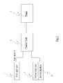
- Fig.1 is the first schematic diagram of the input device with the input switch according to the present invention.
- the first embodiment of input device with the input switch in accordance with the present invention includes a first input unit 1 for producing input signals 11, a second input unit 2 having switch interface 21, a timer 3 for setting a predefined time (not shown) and producing a counting time (not shown), and a control unit 4.
- the control unit 4 turns off the switch interface 21 and activates the timer 3 to produce the counting time after receiving the input signals 11. If the counting time is greater than the predefined time, the control unit 4 activates the switch interface 21.
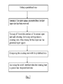
- Fig.2 is the first schematic diagram of the switching method of the input device in accordance with the present invention. As shown in Fig.2 , the switching method of the input device in accordance with the present invention includes the following steps:
- the control unit 4 turns off the switch interface 21 to disconnect signal path between the second input unit 2 and the computer system; and when the counting time is greater than the predefined time, the control unit 4 activates the switch interface to reconnect signal path between the second input unit 2 and the computer system.
- the control unit 4 activates the switch interface to reconnect signal path between the second input unit 2 and the computer system.
- the present disclosure further discloses another embodiment in below.
- the predefined time and the counting time use millisecond value as the minimum unit for measurement.
- a timer 3 When a timer 3 is activated, it transforms a start millisecond value based on year, month, date, hour, minute, and second.
- the start millisecond value is set as base value and starts accumulation by 1 millisecond.
- a timer 3 When a timer 3 is activated, it transforms a start millisecond value based on year, month, date, hour, minute, and second.
- the start millisecond value is set as base value and starts accumulation by 100 milliseconds.
- the range of the predefined time is from 10 milliseconds to 130 milliseconds.
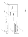
- FIG.3 shows the second schematic diagram of the input device with the input switch in accordance with the present invention.
- This embodiment illustrated in Fig.3 is approximately similar to the embodiment in Fig.1 .
- the difference is that the timer 30 is included in the control unit 40.
Landscapes
- Engineering & Computer Science (AREA)
- General Engineering & Computer Science (AREA)
- Theoretical Computer Science (AREA)
- Human Computer Interaction (AREA)
- Physics & Mathematics (AREA)
- General Physics & Mathematics (AREA)
- Input From Keyboards Or The Like (AREA)
- User Interface Of Digital Computer (AREA)
- Position Input By Displaying (AREA)
Abstract
A input device and switching method thereof is provided. After a first input unit produces the input signals, a control unit turns off the a switch interface to disconnect signal path between a second input unit and the computer system. When a counting time is greater than a predefined time, the control unit activates the switch interface to reconnect signal path between the second input unit and the computer system. Thus, it can prevent unintentional input from touching a plurality of input units by the users..
Description
- The present invention relates to an input device with an input switch and a switching method thereof, and more particularly to an input device with the input switch and a switching method thereof applied to computer.
- The input unit is the passageway for the computer to receive input data. The user can input data through the input unit. The input data will be transformed into an electronic signals by the input unit and stored in the main memory. Computer device such as keyboard, card reader, mouse, light pen, bar code reader, scanner, and digital camera are belonged to the input unit category.
- The conventional computer system has a plurality of input units. However, when the user manipulates a certain input unit, the computer system will not turn off other idle input unit automatically. Thereby, a common defect is emerged. When the user try to manipulate a certain input unit but unintentionally touches other input units, a fault signals is sent into the computer and disturbing the user's normal operating condition if an automatic switching system does not exist, herein the automatic switching system can turn off those idle input units
- Currently, neither a method nor a software system can automatically detect the input source and turn off the other input units, the user can only turn on/off the input unit by themselves to prevent the faulty operation. As a result, it is necessary to develop an input device to prevent unintentional input from touching a plurality of input units by the users..
- The main objective of the present invention is to provide an input device with the input switch and a switching method thereof applied to the computer, which aims to prevent unintentional input from touching a plurality of input units. According to the present invention of the input device with the input switch and switching method thereof, after a first input unit produces an input signal, a control unit turns off a switch interface to disconnect signal path between a second input unit and the computer system; when a counting time is greater than a predefined time, the control unit activates the switch interface to reconnect signal path between the second input unit and the computer system. Thus, it can prevent the faulty operation by the users. The present invention may best be understood through the following description with reference to the accompanying drawings.
-
-
Fig.1 is the first schematic diagram of the input device with the input switch according to the present invention; -
Fig.2 is the first schematic diagram of the input device with the input switch according to the present invention; and -
Fig.3 is the second schematic diagram of the input device with the input switch according to the present invention. -
Fig.1 is the first schematic diagram of the input device with the input switch according to the present invention. As shown inFig.1 , the first embodiment of input device with the input switch in accordance with the present invention includes afirst input unit 1 for producinginput signals 11, a second input unit 2 havingswitch interface 21, atimer 3 for setting a predefined time (not shown) and producing a counting time (not shown), and acontrol unit 4. Thecontrol unit 4 turns off theswitch interface 21 and activates thetimer 3 to produce the counting time after receiving theinput signals 11. If the counting time is greater than the predefined time, thecontrol unit 4 activates theswitch interface 21. -
Fig.2 is the first schematic diagram of the switching method of the input device in accordance with the present invention. As shown inFig.2 , the switching method of the input device in accordance with the present invention includes the following steps: - setting a predefined time (not shown);
- sensing if the
input signals 11 produced from thefirst input unit 1 have been received; - turning off the
switch interface 21 of the second input unit 2 and activating thetimer 3 to produce a counting time, when sensing thefirst input unit 1 has producedinput signals 11; - comparing the counting time with the predefined time; and
- when the counting time is greater than the predefined time, activating the
switch interface 21. - Therefore, according to the present disclosure, after the
first input unit 1 produces theinput signals 11, thecontrol unit 4 turns off theswitch interface 21 to disconnect signal path between the second input unit 2 and the computer system; and when the counting time is greater than the predefined time, thecontrol unit 4 activates the switch interface to reconnect signal path between the second input unit 2 and the computer system. Thus, it can prevent unintentional input from touching a plurality of input units by the users.. - The present disclosure further discloses another embodiment in below. The predefined time and the counting time use millisecond value as the minimum unit for measurement. When a
timer 3 is activated, it transforms a start millisecond value based on year, month, date, hour, minute, and second. The start millisecond value is set as base value and starts accumulation by 1 millisecond. - Another embodiment is described here. When a
timer 3 is activated, it transforms a start millisecond value based on year, month, date, hour, minute, and second. The start millisecond value is set as base value and starts accumulation by 100 milliseconds. - In addition, according to a preferred embodiment, the range of the predefined time is from 10 milliseconds to 130 milliseconds.
- Finally, referring to
Fig.3, Fig.3 shows the second schematic diagram of the input device with the input switch in accordance with the present invention. This embodiment illustrated inFig.3 is approximately similar to the embodiment inFig.1 . The difference is that thetimer 30 is included in thecontrol unit 40.
Claims (13)
- An input device, comprising:a first input unit producing input signals;a second input unit comprising a switch interface;a timer setting a predefined time and producing a counting time; anda control unit, wherein the control unit turns off the switch interface and activates the timer to start the counting time when the control unit receives the input signals.
- The input device according to claim 1, wherein the control unit compares the counting time with the predefined time and activates the switch interface.
- The input device according to claim 2, wherein the predefined time and the counting time are counted with millisecond as the minimum unit of measurement.
- The input device according to claim 3, wherein when the timer is activated, the timer transforms a start millisecond value based on year, month, date, hour, minute, and second.
- The input device according to claim 4, wherein the calculation of the counting time is setting the start millisecond value as base value and starting accumulation by 1 millisecond.
- The input device according to claim 4, wherein the calculation of the counting time is setting the start millisecond value as base value and starting accumulation by 100 milliseconds.
- The input device according to claim 3, wherein the range of the predefined time is from 10 milliseconds to 130 milliseconds.
- A switching method for an input device, comprising steps of:setting a predefined time;sensing if the input signals generated from the first input unit have been received;turning off the switch interface of the second input unit and activating the timing unit to produce a counting time when the input signals have generated by the first input unit;comparing the counting time with the predefined time; andactivating the switch interface when the counting time is greater than the predefined time.
- The switching method of the input device according to claim 8, wherein the predefined time and the counting time use millisecond value as the minimum unit of measurement.
- The switching method of the input device according to claim 9, wherein, when the timer is activated, the timer generates a start millisecond value based on year, month, date, hour, minute, and second.
- The switching method of the input device according to claim 10, wherein the calculation of the counting time is setting the start millisecond value as base value and starting accumulation by 1 millisecond.
- The switching method of the input device according to claim 10, wherein the calculation of the counting time is setting the start millisecond value as base value and starting accumulation by 100 milliseconds.
- The switching method of input device according to claim 9, wherein the range of the predefined time is from 10 milliseconds to 130 milliseconds.
Applications Claiming Priority (1)
| Application Number | Priority Date | Filing Date | Title |
|---|---|---|---|
| TW099147255A TWI453590B (en) | 2010-12-31 | 2010-12-31 | Input unit switching device and its switching method |
Publications (1)
| Publication Number | Publication Date |
|---|---|
| EP2472358A1 true EP2472358A1 (en) | 2012-07-04 |
Family
ID=44503560
Family Applications (1)
| Application Number | Title | Priority Date | Filing Date |
|---|---|---|---|
| EP11171530A Withdrawn EP2472358A1 (en) | 2010-12-31 | 2011-06-27 | Switching device and method for input unit |
Country Status (5)
| Country | Link |
|---|---|
| US (1) | US20120173768A1 (en) |
| EP (1) | EP2472358A1 (en) |
| JP (1) | JP2012141949A (en) |
| KR (1) | KR20120078563A (en) |
| TW (1) | TWI453590B (en) |
Families Citing this family (1)
| Publication number | Priority date | Publication date | Assignee | Title |
|---|---|---|---|---|
| TWI578192B (en) * | 2012-11-09 | 2017-04-11 | 技嘉科技股份有限公司 | Touch method for palm rejection and an electronic device using the same |
Citations (2)
| Publication number | Priority date | Publication date | Assignee | Title |
|---|---|---|---|---|
| WO2004025449A2 (en) * | 2002-09-16 | 2004-03-25 | Koninklijke Philips Electronics N.V. | Method for inputting character and position information |
| EP1681615A1 (en) * | 2003-10-10 | 2006-07-19 | Matsushita Electric Industrial Co., Ltd. | Entering apparatus |
Family Cites Families (11)
| Publication number | Priority date | Publication date | Assignee | Title |
|---|---|---|---|---|
| US4038637A (en) * | 1975-11-24 | 1977-07-26 | Peters Sherman M | Access control system |
| JPH0194415A (en) * | 1987-10-06 | 1989-04-13 | Nec Corp | Digital signal input processing system |
| JPH0742201Y2 (en) * | 1988-12-16 | 1995-09-27 | 株式会社リコー | Electronics |
| JP2833794B2 (en) * | 1989-09-28 | 1998-12-09 | 古野電気株式会社 | Key input processing device |
| JPH04170621A (en) * | 1990-11-05 | 1992-06-18 | Toshiba Corp | Keyboard signal processor |
| US6734796B2 (en) * | 2000-04-04 | 2004-05-11 | Ian J. Forster | Self-check for a detector detecting the proximity of a transportation vessel |
| US6954791B2 (en) * | 2001-01-23 | 2005-10-11 | Intel Corporation | Time-based network connections |
| US6525515B1 (en) * | 2001-09-24 | 2003-02-25 | Supertex, Inc. | Feedback apparatus and method for adaptively controlling power supplied to a hot-pluggable subsystem |
| US20060130154A1 (en) * | 2004-11-30 | 2006-06-15 | Wai Lam | Method and system for protecting and verifying stored data |
| TW200820049A (en) * | 2006-10-20 | 2008-05-01 | Dexin Corp | Select emitting light device of twice-source optical mouse and detecting method for the same |
| US20120032894A1 (en) * | 2010-08-06 | 2012-02-09 | Nima Parivar | Intelligent management for an electronic device |
-
2010
- 2010-12-31 TW TW099147255A patent/TWI453590B/en not_active IP Right Cessation
-
2011
- 2011-06-27 EP EP11171530A patent/EP2472358A1/en not_active Withdrawn
- 2011-06-28 US US13/170,204 patent/US20120173768A1/en not_active Abandoned
- 2011-07-01 KR KR1020110065278A patent/KR20120078563A/en not_active Ceased
- 2011-07-21 JP JP2011159855A patent/JP2012141949A/en active Pending
Patent Citations (2)
| Publication number | Priority date | Publication date | Assignee | Title |
|---|---|---|---|---|
| WO2004025449A2 (en) * | 2002-09-16 | 2004-03-25 | Koninklijke Philips Electronics N.V. | Method for inputting character and position information |
| EP1681615A1 (en) * | 2003-10-10 | 2006-07-19 | Matsushita Electric Industrial Co., Ltd. | Entering apparatus |
Also Published As
| Publication number | Publication date |
|---|---|
| US20120173768A1 (en) | 2012-07-05 |
| TW201227315A (en) | 2012-07-01 |
| JP2012141949A (en) | 2012-07-26 |
| TWI453590B (en) | 2014-09-21 |
| KR20120078563A (en) | 2012-07-10 |
Similar Documents
| Publication | Publication Date | Title |
|---|---|---|
| JP6096900B2 (en) | Information display terminal | |
| CN104992094A (en) | Terminal operation method and terminal | |
| CN105045463A (en) | A message display control method and device | |
| US20170262722A1 (en) | Information processing apparatus, program, and information processing method | |
| CN109543378B (en) | Fingerprint unlocking method and related equipment | |
| CN103513788B (en) | Based on the gesture identification method of gyro sensor, system and mobile terminal | |
| US10488988B2 (en) | Electronic device and method of preventing unintentional touch | |
| CN109388302B (en) | Schedule display method and terminal equipment | |
| CN109194815A (en) | Operating method, device and computer readable storage medium based on multi-screen terminal | |
| CN108108117B (en) | Screen capturing method and device and terminal | |
| JP2020500352A (en) | Information display method, terminal, and storage medium | |
| EP2765482A1 (en) | Handheld electronic apparatus and operation method thereof | |
| CN110114749A (en) | Touch panel input device, touch gesture judging device, touch gesture judging method, and touch gesture judging program | |
| CN113938551A (en) | Caching method and device and electronic equipment | |
| US20080141073A1 (en) | BIOS debugging system and method | |
| CN111949159A (en) | Calibration method and device of touch screen, equipment and storage medium | |
| US20120173768A1 (en) | Switching Device and Method For Input Unit | |
| CN105788565A (en) | Method and device for adjusting brightness | |
| CN104915087B (en) | The method and electronic equipment of information processing | |
| CN105224067A (en) | A kind of method, device and mobile terminal controlling quarter-bell | |
| CN102609080B (en) | Input unit switching device and switching method thereof | |
| CN104951226B (en) | Touch input judging method and electronic device using the touch input judging method | |
| CN104635990B (en) | A method and device for identifying a user's touch screen | |
| CN106786848A (en) | Charging wire insert state suggestion device and charging wire insert state reminding method | |
| US8788730B2 (en) | Method for sending a keycode of a non-keyboard apparatus |
Legal Events
| Date | Code | Title | Description |
|---|---|---|---|
| AK | Designated contracting states |
Kind code of ref document: A1 Designated state(s): AL AT BE BG CH CY CZ DE DK EE ES FI FR GB GR HR HU IE IS IT LI LT LU LV MC MK MT NL NO PL PT RO RS SE SI SK SM TR |
|
| AX | Request for extension of the european patent |
Extension state: BA ME |
|
| PUAI | Public reference made under article 153(3) epc to a published international application that has entered the european phase |
Free format text: ORIGINAL CODE: 0009012 |
|
| STAA | Information on the status of an ep patent application or granted ep patent |
Free format text: STATUS: THE APPLICATION IS DEEMED TO BE WITHDRAWN |
|
| 18D | Application deemed to be withdrawn |
Effective date: 20130105 |