EP2472291A1 - Method for a mud cake thickness determination - Google Patents
Method for a mud cake thickness determination Download PDFInfo
- Publication number
- EP2472291A1 EP2472291A1 EP11250935A EP11250935A EP2472291A1 EP 2472291 A1 EP2472291 A1 EP 2472291A1 EP 11250935 A EP11250935 A EP 11250935A EP 11250935 A EP11250935 A EP 11250935A EP 2472291 A1 EP2472291 A1 EP 2472291A1
- Authority
- EP
- European Patent Office
- Prior art keywords
- mud cake
- frequency signals
- source
- mud
- echo
- Prior art date
- Legal status (The legal status is an assumption and is not a legal conclusion. Google has not performed a legal analysis and makes no representation as to the accuracy of the status listed.)
- Withdrawn
Links
Images


Classifications
-
- G—PHYSICS
- G01—MEASURING; TESTING
- G01V—GEOPHYSICS; GRAVITATIONAL MEASUREMENTS; DETECTING MASSES OR OBJECTS; TAGS
- G01V1/00—Seismology; Seismic or acoustic prospecting or detecting
- G01V1/40—Seismology; Seismic or acoustic prospecting or detecting specially adapted for well-logging
- G01V1/44—Seismology; Seismic or acoustic prospecting or detecting specially adapted for well-logging using generators and receivers in the same well
- G01V1/48—Processing data
- G01V1/50—Analysing data
Definitions
- This invention is related to the methods of the determination of the mud cake formed during drilling.
- a mud cake is formed during drilling with the drilling mud injected onto the well via drill string and drawn off via the openings in the drill bit to provide lubrication during the drilling and drilled-out rock debris wash-over to the surface.
- the mud cake layer is formed as the drilling mud is mixed with the rock debris and/or other solid substances and circulated upwards via the annular area between the drill string outer surface and borehole wall. The mixture covers the borehole wall and forms the mud cake layer.
- One of the functions of the mud cake layer is insulation of the bed from the borehole inner part.
- the mud cake layer is in the industry often referred to as the mud cake or filter cake.
- a method for direct determination of mud cake characteristics during sampling performed during the drilling process is known.
- the method is described in WO 2009/139992 .
- pulse-echo measurements were performed using a high-frequency acoustic detector, and to evaluate the mud cake thickness data of the signal emitted and echo returned were used.
- To determine the mud cake thickness as per this method the sound speed in the mud cake must be known which in practice is usually impossible.
- the suggested method for a mud cake thickness determination provides improved reliability and accuracy and comprises the following. Short-time high-frequency signals are send into a formation from at least two positions located at different distances from a mud cake, reflected echo-signals' arrival times are recorded and a mud cake thickness is determined based on the times measured.
- Such high-frequency signals are sent by one source of high-frequency signals moving to different positions against the mud cake or by means of at least two sources installed at different distances from the mud cake.
- the high-frequency signals' source contact transducers refracted ray transducers, shear wave transducers, hydrophone receivers etc. may be used.
- a source of high-frequency signals can be at the same time used as an acoustic receiver.
- Fig.1 shows sending and reflection of a signal at the drilling mud/ mud cake interface
- Fig. 2 shows pressure waves for a solid mud cake at different distances between a source and the mud cake
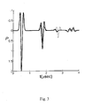
- Fig. 3 pressure waves for the solid mud cake at different attenuation values at drilling mud/ mud cake interface.
- One of the embodiments consists in sending short-time high-frequency signals into the formation at certain time intervals varying the distance from the source to the mud cake by relocating a source of high-frequency signals.
- the other embodiment consists in disposing at least two sources of high-frequency signals at different distances between them and the mud cake. The idea is to use the reflections from the interfaces (both drilling mud/ mud cake and mud cake/ formation ones) as well as in the use of not only echo arrival time but also complete data of the signal (see Fig. 1 ) (for example, reflection amplitudes).
- the algorithm is as follows.
- R Z 2 - Z 1 Z 2 + Z 1
- the sound speed in the drilling mud V m and its density ⁇ m may be considered as known values proceeding, at least, from the drilling mud composition or by means of installing an additional borehole sensor.
- the drilling mud attenuation decrement ⁇ m may be assumed as known (i.e., based on the additional sensor data). Alternatively, it may be estimated through step-by-step echo-pulse measurements at the known sensor position because impedance at the drilling mud/ mud cake interface does not change.
- ⁇ m - V m 2 ⁇ f ⁇ d m ⁇ 1 - d m ⁇ 2 ⁇ ln A d m ⁇ 1 / A d m ⁇ 2
- a ( d ) is the amplitude of the signal reflected from the drilling mud/ mud cake interface providing that the source is at the distance of d from it.
- the mud cake impedance Z mc may be inferred because the drilling mud impedance Z m is known:
- Z mc Z m ⁇ 1 + ⁇ 1 - ⁇ , r
- a ⁇ e ⁇ K mmc d m ⁇ exp ⁇ m ⁇ 2 ⁇ f ⁇ d m V m
- ⁇ K mmc d m ⁇ exp d m d m ⁇ 2 - d m ⁇ 1 ⁇ ln A m ⁇ 1 ln A m ⁇ 2
- the mud cake/formation echo signals may be identified by eliminating the drilling mud- mud cake echo and its multiples. Knowing arrival time of these echoes and the sound speed in the drilling mud and mud cake it is easy to get estimate h mc estimate.
- An additional advantage of this approach consists in the fact that attenuation in the mud cake may also be estimated.
- the signal amplitude is important and the necessity of accounting for the measurement dynamic range arises.
- one of the possible options is introduction of reference borehole measurements. For example, obtaining reflection from the known surface followed by comparing with the echo from mud cake/ formation interface. Therefore it may be possible to avoid direct comparison with the signal from the source, and the dynamic range requirements reduce to a more reasonable value of 10-20 dB and improved data quality may be expected.
- Fig.2 shows pressure waves for the solid mud cake at different distances between the source and mud cake (1mm - solid line, 0.5 mm - dotted line)
- Fig. 3 shows pressure waves for the solid mud cake at different attenuation values on the drilling mud/ mud cake interface (no attenuation - dotted line, in the mud cake only - solid line, both in the drilling mud and mud cake - dashed line).
- the approach above enables obtaining a justified and reasonably accurate estimate of the mud cake thickness and attenuation. Besides, it is a method for the constant monitoring and enables identifying the mud cake onset.
- the frequency it is preferable to reduce the frequency to the maximum extent possible simultaneously retaining the possibility of identifying the echo arrival time. It may be done even for the frequencies corresponding to the wavelengths about h mc -0.5h mc and less. It enables retaining strong enough reflections and enables high impedance measurement accuracy. At a higher frequency (wavelength h mc and less) to measure the echo arrival time simple picking is sufficient. At lower frequencies more complicated signal processing techniques are recommended because the signal and echo begin overlapping. Similarly, a possibility of using a better signal analysis should be provided to identify the mud cake properties. For example, the mud cake will have natural resonance frequencies related to its thickness. They must be highlighted in the signal spectrum. Consequently, during the echo spectral analysis we obtain an additional method for h mc estimation.
- the high-frequency signals' source sensors like contact transducers, refracted ray transducers, shear wave transducers, hydrophones, rolling transducers etc. can be used.
- the hydrophones enable producing a pressure signal and may be used even when direct contact with the mud cake/ formation is not desirable or impossible for some reasons; contact transducers may be used to produce directional (vector) signal that may help obtain more detailed data; refracted ray transducers may ensure a strong excitation in the required direction; rolling transducers may prove quite useful if continuous measurements are required because they constantly contact the interface in question etc.
- ultrasonic immersed emitters hydrophones, surface acoustic wave transducers
- B&K http://www.bkhome.com/
- Reson http://www.reson.com/sw7542.asp
- Panametrics http://www.olympus-ims.com/en/panametrics-ndt-ultrasonic/).
- Force technology etc.
Landscapes
- Physics & Mathematics (AREA)
- Life Sciences & Earth Sciences (AREA)
- Engineering & Computer Science (AREA)
- Acoustics & Sound (AREA)
- Environmental & Geological Engineering (AREA)
- Geology (AREA)
- Remote Sensing (AREA)
- General Life Sciences & Earth Sciences (AREA)
- General Physics & Mathematics (AREA)
- Geophysics (AREA)
- Length Measuring Devices Characterised By Use Of Acoustic Means (AREA)
- Geophysics And Detection Of Objects (AREA)
- Investigating Or Analyzing Materials By The Use Of Ultrasonic Waves (AREA)
Abstract
Description
- This invention is related to the methods of the determination of the mud cake formed during drilling.
- A mud cake is formed during drilling with the drilling mud injected onto the well via drill string and drawn off via the openings in the drill bit to provide lubrication during the drilling and drilled-out rock debris wash-over to the surface. The mud cake layer is formed as the drilling mud is mixed with the rock debris and/or other solid substances and circulated upwards via the annular area between the drill string outer surface and borehole wall. The mixture covers the borehole wall and forms the mud cake layer. One of the functions of the mud cake layer is insulation of the bed from the borehole inner part. The mud cake layer is in the industry often referred to as the mud cake or filter cake.
- A method for direct determination of mud cake characteristics during sampling performed during the drilling process is known. The method is described in
WO 2009/139992 . In the known method pulse-echo measurements were performed using a high-frequency acoustic detector, and to evaluate the mud cake thickness data of the signal emitted and echo returned were used. To determine the mud cake thickness as per this method the sound speed in the mud cake must be known which in practice is usually impossible. - The suggested method for a mud cake thickness determination provides improved reliability and accuracy and comprises the following. Short-time high-frequency signals are send into a formation from at least two positions located at different distances from a mud cake, reflected echo-signals' arrival times are recorded and a mud cake thickness is determined based on the times measured.
- Such high-frequency signals are sent by one source of high-frequency signals moving to different positions against the mud cake or by means of at least two sources installed at different distances from the mud cake.
- As the high-frequency signals' source contact transducers, refracted ray transducers, shear wave transducers, hydrophone receivers etc. may be used.
- A source of high-frequency signals can be at the same time used as an acoustic receiver.
- Additionally an attenuation in the mud cake can be determined.
- Besides, a spectral analysis of echo signals can be conducted.
- The invention is explained by drawings in which
Fig.1 shows sending and reflection of a signal at the drilling mud/ mud cake interface,Fig. 2 shows pressure waves for a solid mud cake at different distances between a source and the mud cake,Fig. 3 - pressure waves for the solid mud cake at different attenuation values at drilling mud/ mud cake interface. - In the known method of the mud cake thickness determination described in
WO 2009/139992B echo-pulse measurements were used to evaluate a mud cake thickness hmc and the hmc was evaluated based on the echo arrival time data:
where Vmc is the sound speed in the mud cake, and t - the time of the signal propagation in the mud cake. To implement this method Vmc must be known. It would also be preferable to use signal frequency f values around f = Vmc /2hmc and higher. Unfortunately, in practice the sound speed in the mud cake is usually unknown. - To solve this problem it is proposed to send short-time high-frequency signals into a formation and listen for echo for different locations of a high-frequency signals source relative to a mud cake. One of the embodiments consists in sending short-time high-frequency signals into the formation at certain time intervals varying the distance from the source to the mud cake by relocating a source of high-frequency signals. The other embodiment consists in disposing at least two sources of high-frequency signals at different distances between them and the mud cake. The idea is to use the reflections from the interfaces (both drilling mud/ mud cake and mud cake/ formation ones) as well as in the use of not only echo arrival time but also complete data of the signal (see
Fig. 1 ) (for example, reflection amplitudes). Real muds and mudcakes strongly attenuate acoustic waves. In effect, due to the attenuation the echo may not appear until a transducer is close enough to the mud cake surface. Quantitatively the attenuation is characterized by the attenuation decrement δ. Over one distance equal to the wave length the wave amplitude reduced by factor of e -δ . It means that the wave amplitude with the frequency f at the distance of d reduces by factor of
- There are several unknown values - δm, hmc, Vmc· If the echo arrival time is known it should be possible to evaluate only one of them. Consequently, additional information is required - two independent values minimum. These are the wave amplitude decay when the transducer position is changed and drilling mud/ mud cake reflection coefficient.
- The algorithm is as follows. The signal transmission and reflection coefficients when a wave passes from
medium 1 tomedium 2 are expressed as:
where Z = ρV means complete acoustic impedance of the medium. If R is negative, it means that π -phase shift of the reflected wave relative to the incident wave takes place. We consider three different cases: reflection from drilling mud/ mud cake interface when the source is at a distance from it (1), reflection from mud cake/formation interface when the source is pressed to the mud cake (2) and reflection from mud cake/formation interface when the source is at a distance from the mud cake (3). In all these options the wave propagates via the medium with the attenuation and is reflected/ transmitted at the interfaces. The resulting amplitude reduction after the first wave return will be as follows (seeFig. 1 ):


where dm is the distance between the transducer and drilling mud/ mud cake interface. These equations are written for 1D case, which is true for our measurements due to the small size of the transducer and mud cake thickness as compared with the borehole radius. The sound speed in the drilling mud Vm and its density ρm may be considered as known values proceeding, at least, from the drilling mud composition or by means of installing an additional borehole sensor. The drilling mud attenuation decrement δm may be assumed as known (i.e., based on the additional sensor data). Alternatively, it may be estimated through step-by-step echo-pulse measurements at the known sensor position because impedance at the drilling mud/ mud cake interface does not change. In case of using more than one source the difference in positions is known and in case of moving source it can be done by, for example, installing position sensors on the motor. Due to the echo-pulse measurements at the distances of d m1 and d m2 and obtaining the ratio between them δm may be estimated:
- Where A(d) is the amplitude of the signal reflected from the drilling mud/
mud cake interface providing that the source is at the distance of d from it. Then from the echo signal from the drilling mud/ mud cake interface the mud cake impedance Zmc may be inferred because the drilling mud impedance Zm is known:
- Or, in a more convenient form

- The mud cake density ρmc may be estimated with the reasonable accuracy (30-40%), if the weighting additive is known and an admission of the mud cake average density is made. It enables estimation of the sound speed in the mud cake as Vmc = Zmc / Pmc . The mud cake/formation echo signals may be identified by eliminating the drilling mud- mud cake echo and its multiples. Knowing arrival time of these echoes and the sound speed in the drilling mud and mud cake it is easy to get estimate hmc estimate. An additional advantage of this approach consists in the fact that attenuation in the mud cake may also be estimated. It may be done if the formation impedance Z f is known (for example, by the known formation density and sound speed) using the equations above depending on the sensor location. All the parameters in these equations, except the mud cake attenuation decrement δmc are either known or estimated during the procedure above.
- To measure the acoustic impedance one should bear in mind that the signal amplitude is important and the necessity of accounting for the measurement dynamic range arises. To reduce the requirements, one of the possible options is introduction of reference borehole measurements. For example, obtaining reflection from the known surface followed by comparing with the echo from mud cake/ formation interface. Therefore it may be possible to avoid direct comparison with the signal from the source, and the dynamic range requirements reduce to a more reasonable value of 10-20 dB and improved data quality may be expected.
- The illustration of the approach above with the numerically calculated waveforms as well as the drilling mud and mud cake attenuation effect are shown in
Fig.2 ,3 for the pressure waveforms normalized to the source signal amplitude.Fig. 2 shows pressure waves for the solid mud cake at different distances between the source and mud cake (1mm - solid line, 0.5 mm - dotted line),Fig. 3 shows pressure waves for the solid mud cake at different attenuation values on the drilling mud/ mud cake interface (no attenuation - dotted line, in the mud cake only - solid line, both in the drilling mud and mud cake - dashed line). The approach above enables obtaining a justified and reasonably accurate estimate of the mud cake thickness and attenuation. Besides, it is a method for the constant monitoring and enables identifying the mud cake onset. - It is preferable to reduce the frequency to the maximum extent possible simultaneously retaining the possibility of identifying the echo arrival time. It may be done even for the frequencies corresponding to the wavelengths about hmc-0.5hmc and less. It enables retaining strong enough reflections and enables high impedance measurement accuracy. At a higher frequency (wavelength hmc and less) to measure the echo arrival time simple picking is sufficient. At lower frequencies more complicated signal processing techniques are recommended because the signal and echo begin overlapping. Similarly, a possibility of using a better signal analysis should be provided to identify the mud cake properties. For example, the mud cake will have natural resonance frequencies related to its thickness. They must be highlighted in the signal spectrum. Consequently, during the echo spectral analysis we obtain an additional method for hmc estimation.
- As the high-frequency signals' source sensors like contact transducers, refracted ray transducers, shear wave transducers, hydrophones, rolling transducers etc. can be used. The hydrophones enable producing a pressure signal and may be used even when direct contact with the mud cake/ formation is not desirable or impossible for some reasons; contact transducers may be used to produce directional (vector) signal that may help obtain more detailed data; refracted ray transducers may ensure a strong excitation in the required direction; rolling transducers may prove quite useful if continuous measurements are required because they constantly contact the interface in question etc. For the method implementation, for example, ultrasonic immersed emitters (hydrophones, surface acoustic wave transducers) from such companies as Physical Acoustics Corporation (hftp://www.pacndt.com/index.aspx?go=products&focus=/multichannel/pcidsp.htm), B&K (http://www.bkhome.com/),Reson, http://www.reson.com/sw7542.asp), Panametrics (http://www.olympus-ims.com/en/panametrics-ndt-ultrasonic/). Onda, Force technology etc. may be used.
Claims (13)
- Method for a mud cake thickness determination, comprising sending short high-frequency signals to a formation, recording arrival times of reflected echo signals, and determining a mud cake thickness based on the measured times, characterized by that the high-frequency signals are sent from at least two positions located at different distances from the mud cake.
- Method of Claim 1 wherein the high-frequency signals are sent by one source of high-frequency signals moving to different positions against the mud cake.
- Method of Claim 2 wherein a contact transducer is used as the source of high-frequency signals.
- Method of Claim 2 wherein a shear-wave transducer is used as the source of high-frequency signals.
- Method of Claim 2 wherein a refracted ray transducer is used as the source of high-frequency signals.
- Method of Claim 2 wherein the high-frequency signal source is simultaneously an acoustic receiver.
- Method of Claim 1 wherein the high-frequency signals are sent by at least two sources of high-frequency signals installed at different distances from the mud cake.
- Method of Claim 6 wherein contact transducers are used as the sources of high-frequency signals.
- Method of Claim 6 wherein shear-wave transducers are used as the sources of high-frequency signals.
- Method of Claim 6 wherein refracted ray transducers are used as the sources of high-frequency signals.
- Method of Claim 6 wherein the high-frequency signal sources are simultaneously acoustic receivers.
- Method of Claim 1 wherein a mud cake attenuation is additionally determined.
- Method of Claim 1 wherein echo-signals' spectral analysis is additionally performed.
Applications Claiming Priority (1)
| Application Number | Priority Date | Filing Date | Title |
|---|---|---|---|
| RU2010154216/03A RU2466273C2 (en) | 2010-12-30 | 2010-12-30 | Method to determine thickness of clayey crust |
Publications (1)
| Publication Number | Publication Date |
|---|---|
| EP2472291A1 true EP2472291A1 (en) | 2012-07-04 |
Family
ID=45476368
Family Applications (1)
| Application Number | Title | Priority Date | Filing Date |
|---|---|---|---|
| EP11250935A Withdrawn EP2472291A1 (en) | 2010-12-30 | 2011-12-23 | Method for a mud cake thickness determination |
Country Status (3)
| Country | Link |
|---|---|
| US (1) | US9081121B2 (en) |
| EP (1) | EP2472291A1 (en) |
| RU (1) | RU2466273C2 (en) |
Cited By (1)
| Publication number | Priority date | Publication date | Assignee | Title |
|---|---|---|---|---|
| CN115992689A (en) * | 2023-03-23 | 2023-04-21 | 中海油田服务股份有限公司 | Ultrasonic imaging logging while drilling device and logging method |
Families Citing this family (4)
| Publication number | Priority date | Publication date | Assignee | Title |
|---|---|---|---|---|
| US9778393B2 (en) * | 2014-05-05 | 2017-10-03 | Vale S.A. | Method and system for density correction for geophysical well logging inside drilling rods |
| US10927659B2 (en) * | 2015-12-11 | 2021-02-23 | Halliburton Energy Services, Inc. | Mud cake correction of formation measurement data |
| CN113482634B (en) * | 2021-08-30 | 2022-09-20 | 盾构及掘进技术国家重点实验室 | System and method for monitoring mud cake of cutter head of slurry shield based on ultrasonic ranging |
| WO2023250080A1 (en) * | 2022-06-23 | 2023-12-28 | Baker Hughes Oilfield Operations Llc | Determinations of standoff and mud density with gamma density and acoustic tool responses |
Citations (5)
| Publication number | Priority date | Publication date | Assignee | Title |
|---|---|---|---|---|
| US4780858A (en) * | 1986-12-29 | 1988-10-25 | Shell Oil Company | Borehole televiewer mudcake monitor |
| US5763773A (en) * | 1996-09-20 | 1998-06-09 | Halliburton Energy Services, Inc. | Rotating multi-parameter bond tool |
| US20020070017A1 (en) * | 2000-12-07 | 2002-06-13 | Soliman Mohamed Y. | Method and apparatus for treating a wellbore with vibratory waves to remove particles therefrom |
| WO2002068796A1 (en) * | 2001-02-27 | 2002-09-06 | Pathfinder Energy Services Limited | Borehole shape determination |
| WO2009139992A2 (en) | 2008-05-16 | 2009-11-19 | Schlumberger Canada Limited | Methods and apparatus to control a formation testing operation based on a mudcake leakage |
Family Cites Families (7)
| Publication number | Priority date | Publication date | Assignee | Title |
|---|---|---|---|---|
| US4365321A (en) * | 1980-07-03 | 1982-12-21 | Wpc, Inc. | Sonic logging tool |
| SU1516959A1 (en) * | 1987-06-02 | 1989-10-23 | Кишиневское Проектно-Конструкторское Бюро Автоматизированных Систем Управления | Ultrasonic device for inspecting the quality of articles |
| RU2056860C1 (en) * | 1992-06-29 | 1996-03-27 | Виктор Иванович Дикарев | Method for testing functional state of a sportsmen |
| RU2097746C1 (en) * | 1996-06-06 | 1997-11-27 | Общество с ограниченной ответственностью "ИТАР" | Device and method designed to measure geometrical dimensions and warping of plates |
| US6513385B1 (en) * | 2001-05-08 | 2003-02-04 | Halliburton Energy Services, Inc. | Acoustic sensor for pipeline deposition characterization and monitoring |
| RU2257563C2 (en) * | 2003-02-19 | 2005-07-27 | Федеральное государственное унитарное научно-производственное предприятие "Геологоразведка" | Method for determining condition of beams and device for realization of said method |
| EP1693685B1 (en) * | 2005-02-22 | 2014-10-22 | Services Petroliers Schlumberger | An electromagnetic probe |
-
2010
- 2010-12-30 RU RU2010154216/03A patent/RU2466273C2/en not_active IP Right Cessation
-
2011
- 2011-12-06 US US13/311,864 patent/US9081121B2/en not_active Expired - Fee Related
- 2011-12-23 EP EP11250935A patent/EP2472291A1/en not_active Withdrawn
Patent Citations (5)
| Publication number | Priority date | Publication date | Assignee | Title |
|---|---|---|---|---|
| US4780858A (en) * | 1986-12-29 | 1988-10-25 | Shell Oil Company | Borehole televiewer mudcake monitor |
| US5763773A (en) * | 1996-09-20 | 1998-06-09 | Halliburton Energy Services, Inc. | Rotating multi-parameter bond tool |
| US20020070017A1 (en) * | 2000-12-07 | 2002-06-13 | Soliman Mohamed Y. | Method and apparatus for treating a wellbore with vibratory waves to remove particles therefrom |
| WO2002068796A1 (en) * | 2001-02-27 | 2002-09-06 | Pathfinder Energy Services Limited | Borehole shape determination |
| WO2009139992A2 (en) | 2008-05-16 | 2009-11-19 | Schlumberger Canada Limited | Methods and apparatus to control a formation testing operation based on a mudcake leakage |
Cited By (1)
| Publication number | Priority date | Publication date | Assignee | Title |
|---|---|---|---|---|
| CN115992689A (en) * | 2023-03-23 | 2023-04-21 | 中海油田服务股份有限公司 | Ultrasonic imaging logging while drilling device and logging method |
Also Published As
| Publication number | Publication date |
|---|---|
| US9081121B2 (en) | 2015-07-14 |
| US20120170405A1 (en) | 2012-07-05 |
| RU2010154216A (en) | 2012-07-20 |
| RU2466273C2 (en) | 2012-11-10 |
Similar Documents
| Publication | Publication Date | Title |
|---|---|---|
| Winkler et al. | Technique for measuring ultrasonic velocity and attenuation spectra in rocks under pressure | |
| US4283953A (en) | Method and apparatus for determining a granularity property of a subsurface formation around a borehole | |
| US10253615B2 (en) | Method and a system for ultrasonic inspection of well bores | |
| US4596143A (en) | Method and apparatus for detecting fractures by ultrasonic echography along the wall of a material or a formation | |
| EP0837217B1 (en) | Downhole tool | |
| US7614302B2 (en) | Acoustic fluid analysis method | |
| US20170038344A1 (en) | Improvements in or relating to sonar apparatus | |
| Kim et al. | IE–SASW method for nondestructive evaluation of concrete structure | |
| AU2008297648B2 (en) | Acoustic thickness measurements using gas as a coupling medium | |
| US9081121B2 (en) | Method for a mud cake thickness determination | |
| CN103362502B (en) | Acoustic logging eliminates the method for direct-wave jamming, system and acoustic logging instrument | |
| CN114651110A (en) | Detection and evaluation of ultrasonic subsurface backscatter | |
| CN102539530A (en) | Method for measuring echo reduction/reflection coefficient of underwater sound passive material based on time reversal focusing | |
| CA1129066A (en) | Method and apparatus for acoustically investigating a casing and casing cement bond in borehole penetrating an earth formation | |
| CN105008663A (en) | Method for revealing anomalous discontinuity interfaces in pore pressures in non-drilled geological formations and a system implementing it | |
| US9702855B2 (en) | Acoustic interface device | |
| RU2182318C2 (en) | Method of measurement of acoustic supersonic wave velocity in rock pieces | |
| JPH04323553A (en) | Method and device for ultrasonic resonance flaw detection | |
| US4458340A (en) | Borehole sonic method for porosity characterization | |
| WO1992008128A1 (en) | Detecting defects in concrete | |
| GB2034888A (en) | Method and apparatus for determining a granularity property of a subsurface formation around a borehole | |
| Dunlop | Measurement of acoustic attenuation in marine sediments by impedance tube | |
| Jiang et al. | Multiple reflection wave detection method based on inversion of multilayer material transfer function | |
| GB1599067A (en) | Ultrasonic testing | |
| US4587973A (en) | Ultrasonic method and means for measuring blood flow and the like using autocorrelation |
Legal Events
| Date | Code | Title | Description |
|---|---|---|---|
| AK | Designated contracting states |
Kind code of ref document: A1 Designated state(s): AL AT BE BG CH CY CZ DE DK EE ES FI FR GB GR HR HU IE IS IT LI LT LU LV MC MK MT NL NO PL PT RO RS SE SI SK SM TR |
|
| AX | Request for extension of the european patent |
Extension state: BA ME |
|
| PUAI | Public reference made under article 153(3) epc to a published international application that has entered the european phase |
Free format text: ORIGINAL CODE: 0009012 |
|
| 17P | Request for examination filed |
Effective date: 20121219 |
|
| RIC1 | Information provided on ipc code assigned before grant |
Ipc: G01V 1/50 20060101AFI20151105BHEP |
|
| GRAP | Despatch of communication of intention to grant a patent |
Free format text: ORIGINAL CODE: EPIDOSNIGR1 |
|
| INTG | Intention to grant announced |
Effective date: 20151211 |
|
| RAP1 | Party data changed (applicant data changed or rights of an application transferred) |
Owner name: SCHLUMBERGER HOLDINGS LIMITED Owner name: PRAD RESEARCH AND DEVELOPMENT LIMITED Owner name: SERVICES PETROLIERS SCHLUMBERGER Owner name: SCHLUMBERGER TECHNOLOGY B.V. |
|
| RIN1 | Information on inventor provided before grant (corrected) |
Inventor name: FUKUHARA, MASAFUMI Inventor name: ZAZOVSKY, ALEXANDER Inventor name: ZHARNIKOV, TIMUR Inventor name: GARCIA-OSUNA, FERNANDO |
|
| STAA | Information on the status of an ep patent application or granted ep patent |
Free format text: STATUS: THE APPLICATION IS DEEMED TO BE WITHDRAWN |
|
| 18D | Application deemed to be withdrawn |
Effective date: 20160422 |