EP2472242A2 - Brazed Joint Strain Shift Detection Method For Monitoring Instrument High Cycle Fatigue Life - Google Patents
Brazed Joint Strain Shift Detection Method For Monitoring Instrument High Cycle Fatigue Life Download PDFInfo
- Publication number
- EP2472242A2 EP2472242A2 EP11194753A EP11194753A EP2472242A2 EP 2472242 A2 EP2472242 A2 EP 2472242A2 EP 11194753 A EP11194753 A EP 11194753A EP 11194753 A EP11194753 A EP 11194753A EP 2472242 A2 EP2472242 A2 EP 2472242A2
- Authority
- EP
- European Patent Office
- Prior art keywords
- joint
- rake
- inlet
- braze joint
- braze
- Prior art date
- Legal status (The legal status is an assumption and is not a legal conclusion. Google has not performed a legal analysis and makes no representation as to the accuracy of the status listed.)
- Granted
Links
- 238000001514 detection method Methods 0.000 title description 4
- 238000012544 monitoring process Methods 0.000 title 1
- 238000000034 method Methods 0.000 claims description 13
- 0 C(C1)C2[C@]1C*C2 Chemical compound C(C1)C2[C@]1C*C2 0.000 description 2
- 230000006378 damage Effects 0.000 description 2
- 238000009434 installation Methods 0.000 description 1
- 238000012986 modification Methods 0.000 description 1
- 230000004048 modification Effects 0.000 description 1
- 230000009528 severe injury Effects 0.000 description 1
Images



Classifications
-
- G—PHYSICS
- G01—MEASURING; TESTING
- G01N—INVESTIGATING OR ANALYSING MATERIALS BY DETERMINING THEIR CHEMICAL OR PHYSICAL PROPERTIES
- G01N3/00—Investigating strength properties of solid materials by application of mechanical stress
- G01N3/32—Investigating strength properties of solid materials by application of mechanical stress by applying repeated or pulsating forces
-
- G—PHYSICS
- G01—MEASURING; TESTING
- G01M—TESTING STATIC OR DYNAMIC BALANCE OF MACHINES OR STRUCTURES; TESTING OF STRUCTURES OR APPARATUS, NOT OTHERWISE PROVIDED FOR
- G01M5/00—Investigating the elasticity of structures, e.g. deflection of bridges or air-craft wings
- G01M5/0033—Investigating the elasticity of structures, e.g. deflection of bridges or air-craft wings by determining damage, crack or wear
-
- G—PHYSICS
- G01—MEASURING; TESTING
- G01M—TESTING STATIC OR DYNAMIC BALANCE OF MACHINES OR STRUCTURES; TESTING OF STRUCTURES OR APPARATUS, NOT OTHERWISE PROVIDED FOR
- G01M5/00—Investigating the elasticity of structures, e.g. deflection of bridges or air-craft wings
- G01M5/0083—Investigating the elasticity of structures, e.g. deflection of bridges or air-craft wings by measuring variation of impedance, e.g. resistance, capacitance, induction
-
- G—PHYSICS
- G01—MEASURING; TESTING
- G01N—INVESTIGATING OR ANALYSING MATERIALS BY DETERMINING THEIR CHEMICAL OR PHYSICAL PROPERTIES
- G01N2203/00—Investigating strength properties of solid materials by application of mechanical stress
- G01N2203/0001—Type of application of the stress
- G01N2203/0005—Repeated or cyclic
-
- G—PHYSICS
- G01—MEASURING; TESTING
- G01N—INVESTIGATING OR ANALYSING MATERIALS BY DETERMINING THEIR CHEMICAL OR PHYSICAL PROPERTIES
- G01N2203/00—Investigating strength properties of solid materials by application of mechanical stress
- G01N2203/0014—Type of force applied
- G01N2203/0016—Tensile or compressive
- G01N2203/0017—Tensile
-
- G—PHYSICS
- G01—MEASURING; TESTING
- G01N—INVESTIGATING OR ANALYSING MATERIALS BY DETERMINING THEIR CHEMICAL OR PHYSICAL PROPERTIES
- G01N2203/00—Investigating strength properties of solid materials by application of mechanical stress
- G01N2203/0058—Kind of property studied
- G01N2203/0069—Fatigue, creep, strain-stress relations or elastic constants
- G01N2203/0073—Fatigue
-
- G—PHYSICS
- G01—MEASURING; TESTING
- G01N—INVESTIGATING OR ANALYSING MATERIALS BY DETERMINING THEIR CHEMICAL OR PHYSICAL PROPERTIES
- G01N2203/00—Investigating strength properties of solid materials by application of mechanical stress
- G01N2203/02—Details not specific for a particular testing method
- G01N2203/06—Indicating or recording means; Sensing means
- G01N2203/0664—Indicating or recording means; Sensing means using witness specimens
Definitions
- This invention relates to turbomachinery instrumentation and, specifically, to a technique for early detection of stress/strain in the instrumentation over a predetermined threshold level.
- inlet rakes are used to monitor temperature, pressure, velocity and/or other parameters of air entering the turbine inlet and flowing across the rake. They are typically mounted to the inlet sidewall in cantilevered fashion, with the sensor beam or tube extending into the flowpath. Conditions within the flowpath can cause vibrations that may excite the natural or resonance frequency of the beam, causing catastrophic failure of the beam, which may then also result in severe damage to the downstream turbine blades or other flowpath components.
- the present invention resides in a method of determining when a component exceeds a predetermined stress level that is less than a fatigue failure level for the component comprising: providing a braze joint in a high stress area of a target component, the braze joint designed to accommodate stress/strain up to the predetermined threshold level; measuring strain at the braze joint; observing a shift in strain indicative of a failed brazed joint; and utilizing information obtained in steps (b) and (c) to repair, replace or set a remaining service life for the target component.
- the component may be an instrumentation beam cantilevered from a casing wall at a structural joint, and subject to vibratory stress.
- the invention resides in an inlet rake for a turbine comprising a hollow beam fitted with plural sensors, and a flange body adapted to secure the hollow beam to a turbine inlet duct; a weld joint between said hollow beam and one end of the flange body located proximate the turbine inlet duct; and a braze joint between the hollow beam and an opposite end of the flange body, forward of said weld joint.
- an inlet rake 10 of the type typically used to monitor various flow characteristics of air entering, for example, a turbine inlet.
- the inlet rake is formed as an elongated, tapered hollow body or beam 12 of generally rounded, rectangular cross-sectional shape ( Fig. 4 ), fitted with a plurality of sensors 14 for measuring, air pressure, temperature, velocity and/or other flow parameters of air entering the turbine inlet and flowing across the rake.
- the inlet rake 10 mounts to a duct or casing wall (indicated at 24 in Fig. 1 ) at a flange body 16 that includes a cylindrical portion 18 and a radial flange portion 20. Tubes and/or sensor leads, generally indicated at 22, are fixed to the back side of the flange portion 20 which, upon installation, lies on the other side of the duct or casing wall, outside the flow path.
- the hollow body or beam 12 is essentially cantilevered from the casing wall and projecting into the air inlet flowpath, and is thus subject to high vibratory stresses, with peak stresses occurring at the flange portion 20, where the latter is bolted to the casing wall, and where the hollow body or beam 12 is welded to the flange portion (indicated at W in Figs. 3 and 4 . If the natural frequency of the hollow beam 12 is excited into resonance, the inlet rake 10 can fail at the welded joint and a separated beam 12 can also cause damage to flow path components downstream of the turbine inlet.
- this invention provides a technique or methodology for detecting stress/strain levels in the inlet rake 10 that exceed a predetermined threshold stress level that is nevertheless below the Goodman limit of the inlet rake.
- the Goodman limit is material specific, and refers to the level of alternating strain the particular material can withstand for 1 million cycles before high cycle fatigue failure occurs.
- a braze joint is located at 26 (see Figs. 1-3 , 5 and 6 ) in an area of high stress, sized for a particular material limit.
- the braze joint is added where the hollow beam 12 is joined with the flange body 16, rearward of the main structural joint where the beam 12 is welded to the flange portion 20 that, in turn, is joined to the casing or duct wall 24 by bolts or other means. Since the length of the rake determines its natural frequency, the braze joint 26 effectively, albeit artificially, sets a new length for the rake in terms of establishing the natural frequency of the rake.
- the braze joint 26 is located approximately 2.6 inches ahead of the nearest edge of the flange portion 20, as best appreciated from Fig. 3 . It will be understood, however, that the exact distance is not critical and may be varied. It is important that the braze joint 26 be located closer to the free edge of the beam 12 than the weld joint. In order to monitor the strain at the braze joint, at strain gauges 28, 30 are located along the braze joint 26 with approximately a 90° spacing therebetween as best seen in Figs. 5 and 6 .
- the braze joint 26 is sized to handle up to a desired predetermined stress level, preferably below the Goodman limit for the particular braze material. In the event higher than expected stress/strain levels are experienced by the braze joint, the braze joint begins to fail, causing a small crack that can be visually noted. In addition, a shift in the strain resulting from the crack can be monitored and plotted. For example, Fig. 7 shows a strain curve where strain in microstrains is plotted against time in seconds. The plot represents a beam at resonance frequency with the braze joint implemented. The curve shows a significant downward shift in strain at about 6-7 thousand seconds, indicating that the braze joint has cracked, the beam has dropped out of resonance, and that the predetermined threshold stress/strain level has been exceeded.
- the failure of the braze joint 26 resets the length and thus the natural frequency of the beam 12.
- the rake is returned to an at least temporarily safe condition.
- the rake will then be inspected and depending on where the threshold stress/strain level has been set, repaired or replaced. It may also be possible to permit the rake to remain in use, noting the remaining cycles before the Goodman material limit of the beam is reached.
- early failure of the braze joint enables the operator replace, repair or set a remaining service life for the component.
- the disclosed detection method allows the operator to monitor the "health" of the inlet rake in a safe and reliable manner, utilizing the braze joint in the manner of a "fusible link". It should be noted however, that once the braze joint has failed, the rake is subject to resonant frequency failure if higher than expected strain is experienced.
Landscapes
- Physics & Mathematics (AREA)
- General Physics & Mathematics (AREA)
- Aviation & Aerospace Engineering (AREA)
- Engineering & Computer Science (AREA)
- General Health & Medical Sciences (AREA)
- Biochemistry (AREA)
- Analytical Chemistry (AREA)
- Chemical & Material Sciences (AREA)
- Immunology (AREA)
- Pathology (AREA)
- Life Sciences & Earth Sciences (AREA)
- Health & Medical Sciences (AREA)
- Testing Of Devices, Machine Parts, Or Other Structures Thereof (AREA)
- Butt Welding And Welding Of Specific Article (AREA)
Abstract
Description
- This invention relates to turbomachinery instrumentation and, specifically, to a technique for early detection of stress/strain in the instrumentation over a predetermined threshold level.
- Sophisticated instrumentation used to monitor operating conditions in the harsh environment of a turbomachine is complex and expensive. Undetected fatigue failure of such instrumentation can not only involve costly shutdowns for repair and/or replacement of the instrumentation, but it can also result in damage to the machine itself. For example, inlet rakes are used to monitor temperature, pressure, velocity and/or other parameters of air entering the turbine inlet and flowing across the rake. They are typically mounted to the inlet sidewall in cantilevered fashion, with the sensor beam or tube extending into the flowpath. Conditions within the flowpath can cause vibrations that may excite the natural or resonance frequency of the beam, causing catastrophic failure of the beam, which may then also result in severe damage to the downstream turbine blades or other flowpath components.
- There is a need, therefore, to devise a way to monitor and detect a stress/strain level in a component (a turbine inlet rake in the exemplary embodiment) that exceeds a predetermined stress/strain level below that at which the component will fail in fatigue, thus providing the user or operator with a clear indication or early warning that the component is at risk.
- The present invention resides in a method of determining when a component exceeds a predetermined stress level that is less than a fatigue failure level for the component comprising: providing a braze joint in a high stress area of a target component, the braze joint designed to accommodate stress/strain up to the predetermined threshold level; measuring strain at the braze joint; observing a shift in strain indicative of a failed brazed joint; and utilizing information obtained in steps (b) and (c) to repair, replace or set a remaining service life for the target component.
- The component may be an instrumentation beam cantilevered from a casing wall at a structural joint, and subject to vibratory stress.
- From another aspects, the invention resides in an inlet rake for a turbine comprising a hollow beam fitted with plural sensors, and a flange body adapted to secure the hollow beam to a turbine inlet duct; a weld joint between said hollow beam and one end of the flange body located proximate the turbine inlet duct; and a braze joint between the hollow beam and an opposite end of the flange body, forward of said weld joint.
- Embodiments of the invention will now be described, by way of example only, with reference to the accompanying drawings in which:
-
Fig. 1 is a front elevation view of a turbine inlet rake; -
Fig. 2 is a side elevation of the rake shown inFig. 1 ; -
Fig. 3 is a cross section of the flange body removed fromFigs. 1 and 2 and taken along the line 3-3 ofFig. 4 ; -
Fig. 4 is a top plan view of the flange body; -
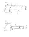
Figs. 5 and 6 are partial elevations of the rake, showing the locations of the braze joint and strain gauges; and -
Fig. 7 is a plot of microstrains vs. time, showing a strain shift upon failure of the braze joint. - In the exemplary but nonlimiting embodiment shown in
Figs. 1-6 , there is illustrated aninlet rake 10 of the type typically used to monitor various flow characteristics of air entering, for example, a turbine inlet. The inlet rake is formed as an elongated, tapered hollow body orbeam 12 of generally rounded, rectangular cross-sectional shape (Fig. 4 ), fitted with a plurality ofsensors 14 for measuring, air pressure, temperature, velocity and/or other flow parameters of air entering the turbine inlet and flowing across the rake. The inlet rake 10 mounts to a duct or casing wall (indicated at 24 inFig. 1 ) at aflange body 16 that includes acylindrical portion 18 and aradial flange portion 20. Tubes and/or sensor leads, generally indicated at 22, are fixed to the back side of theflange portion 20 which, upon installation, lies on the other side of the duct or casing wall, outside the flow path. - In use, the hollow body or
beam 12 is essentially cantilevered from the casing wall and projecting into the air inlet flowpath, and is thus subject to high vibratory stresses, with peak stresses occurring at theflange portion 20, where the latter is bolted to the casing wall, and where the hollow body orbeam 12 is welded to the flange portion (indicated at W inFigs. 3 and 4 . If the natural frequency of thehollow beam 12 is excited into resonance, theinlet rake 10 can fail at the welded joint and aseparated beam 12 can also cause damage to flow path components downstream of the turbine inlet. - In an exemplary but nonlimiting embodiment, this invention provides a technique or methodology for detecting stress/strain levels in the
inlet rake 10 that exceed a predetermined threshold stress level that is nevertheless below the Goodman limit of the inlet rake. The Goodman limit is material specific, and refers to the level of alternating strain the particular material can withstand for 1 million cycles before high cycle fatigue failure occurs. - In order to implement the technique described herein, a braze joint is located at 26 (see
Figs. 1-3 ,5 and 6 ) in an area of high stress, sized for a particular material limit. In the example embodiment, the braze joint is added where thehollow beam 12 is joined with theflange body 16, rearward of the main structural joint where thebeam 12 is welded to theflange portion 20 that, in turn, is joined to the casing orduct wall 24 by bolts or other means. Since the length of the rake determines its natural frequency, the braze joint 26 effectively, albeit artificially, sets a new length for the rake in terms of establishing the natural frequency of the rake. In the exemplary embodiment, thebraze joint 26 is located approximately 2.6 inches ahead of the nearest edge of theflange portion 20, as best appreciated fromFig. 3 . It will be understood, however, that the exact distance is not critical and may be varied. It is important that thebraze joint 26 be located closer to the free edge of thebeam 12 than the weld joint. In order to monitor the strain at the braze joint, atstrain gauges braze joint 26 with approximately a 90° spacing therebetween as best seen inFigs. 5 and 6 . - The
braze joint 26 is sized to handle up to a desired predetermined stress level, preferably below the Goodman limit for the particular braze material. In the event higher than expected stress/strain levels are experienced by the braze joint, the braze joint begins to fail, causing a small crack that can be visually noted. In addition, a shift in the strain resulting from the crack can be monitored and plotted. For example,Fig. 7 shows a strain curve where strain in microstrains is plotted against time in seconds. The plot represents a beam at resonance frequency with the braze joint implemented. The curve shows a significant downward shift in strain at about 6-7 thousand seconds, indicating that the braze joint has cracked, the beam has dropped out of resonance, and that the predetermined threshold stress/strain level has been exceeded. - The failure of the
braze joint 26 resets the length and thus the natural frequency of thebeam 12. By bringing the beam 12 (and rake 10) out of resonance and by resetting the natural frequency, the rake is returned to an at least temporarily safe condition. The rake will then be inspected and depending on where the threshold stress/strain level has been set, repaired or replaced. It may also be possible to permit the rake to remain in use, noting the remaining cycles before the Goodman material limit of the beam is reached. Thus, early failure of the braze joint enables the operator replace, repair or set a remaining service life for the component. In other words, the disclosed detection method allows the operator to monitor the "health" of the inlet rake in a safe and reliable manner, utilizing the braze joint in the manner of a "fusible link". It should be noted however, that once the braze joint has failed, the rake is subject to resonant frequency failure if higher than expected strain is experienced. - While the invention has been described in connection with a turbine inlet rake, it will be appreciated that there are many other applications for the described stress/strain detection method including other instrumentation components, or even turbine components that are subject to severe vibration.
- While the invention has been described in connection with what is presently considered to be the most practical and preferred embodiment, it is to be understood that the invention is not to be limited to the disclosed embodiment, but on the contrary, is intended to cover various modifications and equivalent arrangements included within the spirit and scope of the appended claims.
Claims (13)
- A method of determining when a component (10) exceeds a predetermined stress level that is less than a fatigue failure level for the component comprising:(a) providing a braze joint (26) in a high stress area of a target component (10), the braze joint designed to accommodate stress/strain up to the predetermined threshold level;(b) measuring strain at the braze joint (26);(c) observing a shift in strain indicative of a failed brazed joint; and(d) utilizing information obtained in steps (b) and (c) to repair, replace or set a remaining service life for the target component.
- The method of claim 1, wherein the target component (10) is cantilevered from a support wall (24) at a structural joint subject to failure, and wherein, in step (a), the braze joint (10) is located forward of the structural joint.
- The method of claim 2, wherein step (b) is carried out using strain gauges (28, 30) at the braze joint (26).
- The method of claim 2, wherein the component (10) is an inlet rake for a turbine.
- The method of claim 4, wherein the inlet rake (10) comprises an elongated hollow beam (12) joined to a flange body (16) at the structural joint W, and wherein step (a) is carried out by providing the braze joint (26) at an interface between the hollow beam (12) and the flange body (16), forward of the structural joint.
- The method of claim 3, wherein first and second strain gauges (28,30) are located at the braze joint (26), spaced from each other by about 90°.
- The method of claim 2, wherein the component (10) comprises an instrumentation beam (12) subject to vibratory stress, and wherein: the braze joint (26) is provided in a high stress area of the instrumentation beam, proximate the casing wall, but forward of the structural joint.
- The method of claim 7, wherein said instrumentation beam (12) comprises an inlet rake (10) located in a turbine inlet flowpath, said inlet rake (10) mounting a plurality of sensors (14).
- An inlet rake (10) for a turbine comprising a hollow beam (12) fitted with plural sensors (14), and a flange body (16) adapted to secure said hollow beam (12) to a turbine inlet duct (24); a weld joint W between said hollow beam (12) and one end of said flange body (16) located proximate the turbine inlet duct (24); and
a braze joint (26) between said hollow beam (12) and an opposite end of said flange body (16), forward of said weld joint. - The inlet rake of claim 9, wherein said braze joint (26) is set to fail at a stress level lower than a Goodman limit for a braze material used to form the braze joint.
- The inlet rake of claim 9 or 10, wherein said flange body (16) includes a substantially cylindrical portion (18) and a radial flange portion (20), said weld joint W located in said radial flange portion (20), and said braze joint (16) located in said substantially cylindrical portion (18).
- The inlet rake of claim 11, wherein said hollow beam (12) has a rounded rectangular cross section received in a similarly shaped bore in said flange body (16).
- The inlet rake of claim 11 or 13, in combination with a turbine inlet duct wall, wherein said inlet rake (10) is mounted to said turbine inlet duct wall (24) via fasteners extending through said radial flange portion (20).
Applications Claiming Priority (1)
| Application Number | Priority Date | Filing Date | Title |
|---|---|---|---|
| US12/984,358 US8671770B2 (en) | 2011-01-04 | 2011-01-04 | Brazed joint strain shift detection method for monitoring instrument high cycle fatigue life |
Publications (3)
| Publication Number | Publication Date |
|---|---|
| EP2472242A2 true EP2472242A2 (en) | 2012-07-04 |
| EP2472242A3 EP2472242A3 (en) | 2017-12-27 |
| EP2472242B1 EP2472242B1 (en) | 2019-03-27 |
Family
ID=45524258
Family Applications (1)
| Application Number | Title | Priority Date | Filing Date |
|---|---|---|---|
| EP11194753.7A Not-in-force EP2472242B1 (en) | 2011-01-04 | 2011-12-21 | Brazed joint strain shift detection method for monitoring instrument fatigue |
Country Status (3)
| Country | Link |
|---|---|
| US (1) | US8671770B2 (en) |
| EP (1) | EP2472242B1 (en) |
| CN (1) | CN102607945B (en) |
Families Citing this family (3)
| Publication number | Priority date | Publication date | Assignee | Title |
|---|---|---|---|---|
| US8944678B2 (en) * | 2011-05-13 | 2015-02-03 | General Electric Company | Instrumentation rake assembly |
| US8839662B2 (en) * | 2011-06-27 | 2014-09-23 | United Technologies Corporation | Station probe for gas turbine engines |
| CN109977473A (en) * | 2019-02-26 | 2019-07-05 | 四川易亨机械制造有限公司 | A kind of manufacturing method and device of the compound tongue of high abrasion |
Family Cites Families (16)
| Publication number | Priority date | Publication date | Assignee | Title |
|---|---|---|---|---|
| US2821080A (en) * | 1954-05-06 | 1958-01-28 | Western Electric Co | Tension gage for testing the bond between brazed parts |
| US3845657A (en) * | 1972-02-04 | 1974-11-05 | Westinghouse Electric Corp | Surveillance system including means for detecting impending failure in high pressure, high temperature fluid conducting pipes |
| US4179940A (en) * | 1978-10-02 | 1979-12-25 | Conoco, Inc. | Structural failure detection method |
| DK14092D0 (en) * | 1992-02-06 | 1992-02-06 | Novo Nordisk As | PROCEDURES AND PLANTS FOR TREATING POTATOES AND USING A POTATO TREATMENT PLANT |
| US6191527B1 (en) * | 1999-04-16 | 2001-02-20 | Burle Technologies, Inc. | Stress relieved filament support assembly |
| US6112971A (en) * | 1999-05-12 | 2000-09-05 | General Electric Co. | Multi-nozzle combustion end cover vacuum brazing process |
| US7016825B1 (en) | 2000-10-26 | 2006-03-21 | Vextec Corporation | Method and apparatus for predicting the failure of a component |
| US20040114665A1 (en) * | 2002-12-12 | 2004-06-17 | Sun Park | Cantilevered thermocouple rake |
| JP4027258B2 (en) * | 2003-04-18 | 2007-12-26 | 本田技研工業株式会社 | Debonding inspection method for bonded parts |
| DE102004031222B3 (en) * | 2004-06-28 | 2005-08-11 | Benteler Automobiltechnik Gmbh | Metal plate structural component for a motor vehicle with a design fracture point between at least two plates has a load detector and film sensor connected to an evaluation unit to permit early diagnosis of joint failure |
| US7162373B1 (en) * | 2005-11-21 | 2007-01-09 | General Electric Company | Method and system for assessing life of cracked dovetail in turbine |
| US8596135B2 (en) * | 2006-12-07 | 2013-12-03 | Technion Research and Dvelopment Foundation Ltd. | System and method for monitoring health of structural joints |
| US7715991B2 (en) * | 2007-05-17 | 2010-05-11 | General Electric Company | Systems and methods for monitoring energy system components |
| US7578178B2 (en) * | 2007-09-28 | 2009-08-25 | United Technologies Corporation | Method of inspecting turbine internal cooling features using non-contact scanners |
| US7493809B1 (en) * | 2007-10-04 | 2009-02-24 | General Electric Company | Method and system for measuring deformation in turbine blades |
| US8011251B1 (en) * | 2010-03-24 | 2011-09-06 | General Electric Company | Bifurcated pressure instrumentation rake |
-
2011
- 2011-01-04 US US12/984,358 patent/US8671770B2/en not_active Expired - Fee Related
- 2011-12-21 EP EP11194753.7A patent/EP2472242B1/en not_active Not-in-force
-
2012
- 2012-01-04 CN CN201210012961.5A patent/CN102607945B/en not_active Expired - Fee Related
Non-Patent Citations (1)
| Title |
|---|
| None |
Also Published As
| Publication number | Publication date |
|---|---|
| EP2472242A3 (en) | 2017-12-27 |
| CN102607945B (en) | 2016-01-20 |
| EP2472242B1 (en) | 2019-03-27 |
| US8671770B2 (en) | 2014-03-18 |
| US20120167695A1 (en) | 2012-07-05 |
| CN102607945A (en) | 2012-07-25 |
Similar Documents
| Publication | Publication Date | Title |
|---|---|---|
| US6932560B2 (en) | Apparatus and method for detecting an impact on a rotor blade | |
| US7762153B2 (en) | Method and systems for measuring blade deformation in turbines | |
| EP1813778B1 (en) | Method of monitoring blade vibration in a turbine engine | |
| US8186223B2 (en) | Structural integrity monitoring system | |
| US7157920B2 (en) | Non-destructive monitoring of material integrity | |
| CN114252149B (en) | Method for rapidly evaluating vibration damage and service life of high-low drainage pipeline of thermal power plant | |
| JP2012052536A (en) | System and method for monitoring health of airfoil | |
| CN105606520A (en) | Corrosion sensor for internal structure of machine | |
| EP2472242B1 (en) | Brazed joint strain shift detection method for monitoring instrument fatigue | |
| EP2065567A2 (en) | System for measuring blade deformation in turbines | |
| US7412320B2 (en) | Detection of gas turbine airfoil failure | |
| JP5698766B2 (en) | Method for automatically detecting suction of at least one foreign object by a gas turbine engine | |
| CN109944809A (en) | A method of diagnosis serum recycle failure of pump | |
| JP2011027615A (en) | Integrity monitoring evaluation support system and method of valve device | |
| KR100569143B1 (en) | Residual Stress Measurement Method of Cylinder Block Siamese | |
| JP6254033B2 (en) | Life evaluation method and life evaluation apparatus | |
| Wu et al. | A hybrid fault diagnosis approach for blade crack detection using blade tip timing | |
| KR102775770B1 (en) | Turbine blade condition monitoring system to detect cracks | |
| US20140023498A1 (en) | Rotating stall detection using optical measurement of blade untwist | |
| KR102247305B1 (en) | Gas turbine combustion instability diagnosis system based on zero crossing rate and method thereof | |
| JP2009162647A (en) | Life design method for high temperature equipment welds | |
| CN107894457A (en) | Method for the material inspection without destruction | |
| Rao et al. | Non intrusive method of detecting turbine blade vibration in an operating power plant | |
| JP2001004475A (en) | Crack detector for fluid meter | |
| JP6931874B2 (en) | Measurement data analysis device and measurement data analysis method |
Legal Events
| Date | Code | Title | Description |
|---|---|---|---|
| AK | Designated contracting states |
Kind code of ref document: A2 Designated state(s): AL AT BE BG CH CY CZ DE DK EE ES FI FR GB GR HR HU IE IS IT LI LT LU LV MC MK MT NL NO PL PT RO RS SE SI SK SM TR |
|
| AX | Request for extension of the european patent |
Extension state: BA ME |
|
| PUAI | Public reference made under article 153(3) epc to a published international application that has entered the european phase |
Free format text: ORIGINAL CODE: 0009012 |
|
| PUAL | Search report despatched |
Free format text: ORIGINAL CODE: 0009013 |
|
| AK | Designated contracting states |
Kind code of ref document: A3 Designated state(s): AL AT BE BG CH CY CZ DE DK EE ES FI FR GB GR HR HU IE IS IT LI LT LU LV MC MK MT NL NO PL PT RO RS SE SI SK SM TR |
|
| AX | Request for extension of the european patent |
Extension state: BA ME |
|
| RIC1 | Information provided on ipc code assigned before grant |
Ipc: G01N 3/32 20060101AFI20171120BHEP Ipc: G01M 5/00 20060101ALI20171120BHEP |
|
| STAA | Information on the status of an ep patent application or granted ep patent |
Free format text: STATUS: REQUEST FOR EXAMINATION WAS MADE |
|
| 17P | Request for examination filed |
Effective date: 20180627 |
|
| RBV | Designated contracting states (corrected) |
Designated state(s): AL AT BE BG CH CY CZ DE DK EE ES FI FR GB GR HR HU IE IS IT LI LT LU LV MC MK MT NL NO PL PT RO RS SE SI SK SM TR |
|
| GRAP | Despatch of communication of intention to grant a patent |
Free format text: ORIGINAL CODE: EPIDOSNIGR1 |
|
| STAA | Information on the status of an ep patent application or granted ep patent |
Free format text: STATUS: GRANT OF PATENT IS INTENDED |
|
| INTG | Intention to grant announced |
Effective date: 20181120 |
|
| GRAS | Grant fee paid |
Free format text: ORIGINAL CODE: EPIDOSNIGR3 |
|
| GRAA | (expected) grant |
Free format text: ORIGINAL CODE: 0009210 |
|
| STAA | Information on the status of an ep patent application or granted ep patent |
Free format text: STATUS: THE PATENT HAS BEEN GRANTED |
|
| AK | Designated contracting states |
Kind code of ref document: B1 Designated state(s): AL AT BE BG CH CY CZ DE DK EE ES FI FR GB GR HR HU IE IS IT LI LT LU LV MC MK MT NL NO PL PT RO RS SE SI SK SM TR |
|
| REG | Reference to a national code |
Ref country code: GB Ref legal event code: FG4D |
|
| REG | Reference to a national code |
Ref country code: CH Ref legal event code: EP |
|
| REG | Reference to a national code |
Ref country code: AT Ref legal event code: REF Ref document number: 1113686 Country of ref document: AT Kind code of ref document: T Effective date: 20190415 |
|
| REG | Reference to a national code |
Ref country code: IE Ref legal event code: FG4D |
|
| REG | Reference to a national code |
Ref country code: DE Ref legal event code: R096 Ref document number: 602011057481 Country of ref document: DE |
|
| PG25 | Lapsed in a contracting state [announced via postgrant information from national office to epo] |
Ref country code: LT Free format text: LAPSE BECAUSE OF FAILURE TO SUBMIT A TRANSLATION OF THE DESCRIPTION OR TO PAY THE FEE WITHIN THE PRESCRIBED TIME-LIMIT Effective date: 20190327 Ref country code: NO Free format text: LAPSE BECAUSE OF FAILURE TO SUBMIT A TRANSLATION OF THE DESCRIPTION OR TO PAY THE FEE WITHIN THE PRESCRIBED TIME-LIMIT Effective date: 20190627 Ref country code: SE Free format text: LAPSE BECAUSE OF FAILURE TO SUBMIT A TRANSLATION OF THE DESCRIPTION OR TO PAY THE FEE WITHIN THE PRESCRIBED TIME-LIMIT Effective date: 20190327 Ref country code: FI Free format text: LAPSE BECAUSE OF FAILURE TO SUBMIT A TRANSLATION OF THE DESCRIPTION OR TO PAY THE FEE WITHIN THE PRESCRIBED TIME-LIMIT Effective date: 20190327 |
|
| REG | Reference to a national code |
Ref country code: NL Ref legal event code: MP Effective date: 20190327 |
|
| PG25 | Lapsed in a contracting state [announced via postgrant information from national office to epo] |
Ref country code: HR Free format text: LAPSE BECAUSE OF FAILURE TO SUBMIT A TRANSLATION OF THE DESCRIPTION OR TO PAY THE FEE WITHIN THE PRESCRIBED TIME-LIMIT Effective date: 20190327 Ref country code: GR Free format text: LAPSE BECAUSE OF FAILURE TO SUBMIT A TRANSLATION OF THE DESCRIPTION OR TO PAY THE FEE WITHIN THE PRESCRIBED TIME-LIMIT Effective date: 20190628 Ref country code: LV Free format text: LAPSE BECAUSE OF FAILURE TO SUBMIT A TRANSLATION OF THE DESCRIPTION OR TO PAY THE FEE WITHIN THE PRESCRIBED TIME-LIMIT Effective date: 20190327 Ref country code: RS Free format text: LAPSE BECAUSE OF FAILURE TO SUBMIT A TRANSLATION OF THE DESCRIPTION OR TO PAY THE FEE WITHIN THE PRESCRIBED TIME-LIMIT Effective date: 20190327 Ref country code: BG Free format text: LAPSE BECAUSE OF FAILURE TO SUBMIT A TRANSLATION OF THE DESCRIPTION OR TO PAY THE FEE WITHIN THE PRESCRIBED TIME-LIMIT Effective date: 20190627 Ref country code: NL Free format text: LAPSE BECAUSE OF FAILURE TO SUBMIT A TRANSLATION OF THE DESCRIPTION OR TO PAY THE FEE WITHIN THE PRESCRIBED TIME-LIMIT Effective date: 20190327 |
|
| REG | Reference to a national code |
Ref country code: AT Ref legal event code: MK05 Ref document number: 1113686 Country of ref document: AT Kind code of ref document: T Effective date: 20190327 |
|
| PG25 | Lapsed in a contracting state [announced via postgrant information from national office to epo] |
Ref country code: SK Free format text: LAPSE BECAUSE OF FAILURE TO SUBMIT A TRANSLATION OF THE DESCRIPTION OR TO PAY THE FEE WITHIN THE PRESCRIBED TIME-LIMIT Effective date: 20190327 Ref country code: PT Free format text: LAPSE BECAUSE OF FAILURE TO SUBMIT A TRANSLATION OF THE DESCRIPTION OR TO PAY THE FEE WITHIN THE PRESCRIBED TIME-LIMIT Effective date: 20190727 Ref country code: AL Free format text: LAPSE BECAUSE OF FAILURE TO SUBMIT A TRANSLATION OF THE DESCRIPTION OR TO PAY THE FEE WITHIN THE PRESCRIBED TIME-LIMIT Effective date: 20190327 Ref country code: ES Free format text: LAPSE BECAUSE OF FAILURE TO SUBMIT A TRANSLATION OF THE DESCRIPTION OR TO PAY THE FEE WITHIN THE PRESCRIBED TIME-LIMIT Effective date: 20190327 Ref country code: CZ Free format text: LAPSE BECAUSE OF FAILURE TO SUBMIT A TRANSLATION OF THE DESCRIPTION OR TO PAY THE FEE WITHIN THE PRESCRIBED TIME-LIMIT Effective date: 20190327 Ref country code: IT Free format text: LAPSE BECAUSE OF FAILURE TO SUBMIT A TRANSLATION OF THE DESCRIPTION OR TO PAY THE FEE WITHIN THE PRESCRIBED TIME-LIMIT Effective date: 20190327 Ref country code: RO Free format text: LAPSE BECAUSE OF FAILURE TO SUBMIT A TRANSLATION OF THE DESCRIPTION OR TO PAY THE FEE WITHIN THE PRESCRIBED TIME-LIMIT Effective date: 20190327 Ref country code: EE Free format text: LAPSE BECAUSE OF FAILURE TO SUBMIT A TRANSLATION OF THE DESCRIPTION OR TO PAY THE FEE WITHIN THE PRESCRIBED TIME-LIMIT Effective date: 20190327 |
|
| PG25 | Lapsed in a contracting state [announced via postgrant information from national office to epo] |
Ref country code: PL Free format text: LAPSE BECAUSE OF FAILURE TO SUBMIT A TRANSLATION OF THE DESCRIPTION OR TO PAY THE FEE WITHIN THE PRESCRIBED TIME-LIMIT Effective date: 20190327 Ref country code: SM Free format text: LAPSE BECAUSE OF FAILURE TO SUBMIT A TRANSLATION OF THE DESCRIPTION OR TO PAY THE FEE WITHIN THE PRESCRIBED TIME-LIMIT Effective date: 20190327 |
|
| PG25 | Lapsed in a contracting state [announced via postgrant information from national office to epo] |
Ref country code: IS Free format text: LAPSE BECAUSE OF FAILURE TO SUBMIT A TRANSLATION OF THE DESCRIPTION OR TO PAY THE FEE WITHIN THE PRESCRIBED TIME-LIMIT Effective date: 20190727 Ref country code: AT Free format text: LAPSE BECAUSE OF FAILURE TO SUBMIT A TRANSLATION OF THE DESCRIPTION OR TO PAY THE FEE WITHIN THE PRESCRIBED TIME-LIMIT Effective date: 20190327 |
|
| REG | Reference to a national code |
Ref country code: DE Ref legal event code: R097 Ref document number: 602011057481 Country of ref document: DE |
|
| PG25 | Lapsed in a contracting state [announced via postgrant information from national office to epo] |
Ref country code: DK Free format text: LAPSE BECAUSE OF FAILURE TO SUBMIT A TRANSLATION OF THE DESCRIPTION OR TO PAY THE FEE WITHIN THE PRESCRIBED TIME-LIMIT Effective date: 20190327 |
|
| PLBE | No opposition filed within time limit |
Free format text: ORIGINAL CODE: 0009261 |
|
| STAA | Information on the status of an ep patent application or granted ep patent |
Free format text: STATUS: NO OPPOSITION FILED WITHIN TIME LIMIT |
|
| PG25 | Lapsed in a contracting state [announced via postgrant information from national office to epo] |
Ref country code: SI Free format text: LAPSE BECAUSE OF FAILURE TO SUBMIT A TRANSLATION OF THE DESCRIPTION OR TO PAY THE FEE WITHIN THE PRESCRIBED TIME-LIMIT Effective date: 20190327 |
|
| 26N | No opposition filed |
Effective date: 20200103 |
|
| PG25 | Lapsed in a contracting state [announced via postgrant information from national office to epo] |
Ref country code: TR Free format text: LAPSE BECAUSE OF FAILURE TO SUBMIT A TRANSLATION OF THE DESCRIPTION OR TO PAY THE FEE WITHIN THE PRESCRIBED TIME-LIMIT Effective date: 20190327 |
|
| REG | Reference to a national code |
Ref country code: CH Ref legal event code: PL |
|
| REG | Reference to a national code |
Ref country code: BE Ref legal event code: MM Effective date: 20191231 |
|
| PG25 | Lapsed in a contracting state [announced via postgrant information from national office to epo] |
Ref country code: MC Free format text: LAPSE BECAUSE OF FAILURE TO SUBMIT A TRANSLATION OF THE DESCRIPTION OR TO PAY THE FEE WITHIN THE PRESCRIBED TIME-LIMIT Effective date: 20190327 |
|
| GBPC | Gb: european patent ceased through non-payment of renewal fee |
Effective date: 20191221 |
|
| PG25 | Lapsed in a contracting state [announced via postgrant information from national office to epo] |
Ref country code: GB Free format text: LAPSE BECAUSE OF NON-PAYMENT OF DUE FEES Effective date: 20191221 Ref country code: IE Free format text: LAPSE BECAUSE OF NON-PAYMENT OF DUE FEES Effective date: 20191221 Ref country code: FR Free format text: LAPSE BECAUSE OF NON-PAYMENT OF DUE FEES Effective date: 20191231 Ref country code: LU Free format text: LAPSE BECAUSE OF NON-PAYMENT OF DUE FEES Effective date: 20191221 |
|
| PG25 | Lapsed in a contracting state [announced via postgrant information from national office to epo] |
Ref country code: CH Free format text: LAPSE BECAUSE OF NON-PAYMENT OF DUE FEES Effective date: 20191231 Ref country code: LI Free format text: LAPSE BECAUSE OF NON-PAYMENT OF DUE FEES Effective date: 20191231 Ref country code: BE Free format text: LAPSE BECAUSE OF NON-PAYMENT OF DUE FEES Effective date: 20191231 |
|
| PG25 | Lapsed in a contracting state [announced via postgrant information from national office to epo] |
Ref country code: CY Free format text: LAPSE BECAUSE OF FAILURE TO SUBMIT A TRANSLATION OF THE DESCRIPTION OR TO PAY THE FEE WITHIN THE PRESCRIBED TIME-LIMIT Effective date: 20190327 |
|
| PG25 | Lapsed in a contracting state [announced via postgrant information from national office to epo] |
Ref country code: MT Free format text: LAPSE BECAUSE OF FAILURE TO SUBMIT A TRANSLATION OF THE DESCRIPTION OR TO PAY THE FEE WITHIN THE PRESCRIBED TIME-LIMIT Effective date: 20190327 Ref country code: HU Free format text: LAPSE BECAUSE OF FAILURE TO SUBMIT A TRANSLATION OF THE DESCRIPTION OR TO PAY THE FEE WITHIN THE PRESCRIBED TIME-LIMIT; INVALID AB INITIO Effective date: 20111221 |
|
| PG25 | Lapsed in a contracting state [announced via postgrant information from national office to epo] |
Ref country code: MK Free format text: LAPSE BECAUSE OF FAILURE TO SUBMIT A TRANSLATION OF THE DESCRIPTION OR TO PAY THE FEE WITHIN THE PRESCRIBED TIME-LIMIT Effective date: 20190327 |
|
| PGFP | Annual fee paid to national office [announced via postgrant information from national office to epo] |
Ref country code: DE Payment date: 20221122 Year of fee payment: 12 |
|
| REG | Reference to a national code |
Ref country code: DE Ref legal event code: R081 Ref document number: 602011057481 Country of ref document: DE Owner name: GENERAL ELECTRIC TECHNOLOGY GMBH, CH Free format text: FORMER OWNER: GENERAL ELECTRIC COMPANY, SCHENECTADY, NY, US |
|
| REG | Reference to a national code |
Ref country code: DE Ref legal event code: R119 Ref document number: 602011057481 Country of ref document: DE |
|
| PG25 | Lapsed in a contracting state [announced via postgrant information from national office to epo] |
Ref country code: DE Free format text: LAPSE BECAUSE OF NON-PAYMENT OF DUE FEES Effective date: 20240702 |
|
| PG25 | Lapsed in a contracting state [announced via postgrant information from national office to epo] |
Ref country code: DE Free format text: LAPSE BECAUSE OF NON-PAYMENT OF DUE FEES Effective date: 20240702 |