EP2472185A1 - Heating device - Google Patents
Heating device Download PDFInfo
- Publication number
- EP2472185A1 EP2472185A1 EP10811695A EP10811695A EP2472185A1 EP 2472185 A1 EP2472185 A1 EP 2472185A1 EP 10811695 A EP10811695 A EP 10811695A EP 10811695 A EP10811695 A EP 10811695A EP 2472185 A1 EP2472185 A1 EP 2472185A1
- Authority
- EP
- European Patent Office
- Prior art keywords
- heater
- heating
- heating system
- magnetic member
- coil
- Prior art date
- Legal status (The legal status is an assumption and is not a legal conclusion. Google has not performed a legal analysis and makes no representation as to the accuracy of the status listed.)
- Granted
Links
Images










Classifications
-
- H—ELECTRICITY
- H05—ELECTRIC TECHNIQUES NOT OTHERWISE PROVIDED FOR
- H05B—ELECTRIC HEATING; ELECTRIC LIGHT SOURCES NOT OTHERWISE PROVIDED FOR; CIRCUIT ARRANGEMENTS FOR ELECTRIC LIGHT SOURCES, IN GENERAL
- H05B6/00—Heating by electric, magnetic or electromagnetic fields
- H05B6/02—Induction heating
- H05B6/36—Coil arrangements
- H05B6/365—Coil arrangements using supplementary conductive or ferromagnetic pieces
-
- H—ELECTRICITY
- H05—ELECTRIC TECHNIQUES NOT OTHERWISE PROVIDED FOR
- H05B—ELECTRIC HEATING; ELECTRIC LIGHT SOURCES NOT OTHERWISE PROVIDED FOR; CIRCUIT ARRANGEMENTS FOR ELECTRIC LIGHT SOURCES, IN GENERAL
- H05B6/00—Heating by electric, magnetic or electromagnetic fields
- H05B6/02—Induction heating
- H05B6/10—Induction heating apparatus, other than furnaces, for specific applications
- H05B6/12—Cooking devices
- H05B6/129—Cooking devices induction ovens
Definitions
- the present invention relates to a heating system, and in particular, relates to a heating cooker incorporating an induction current heater as a heat source in a heating box such as a heating oven, roaster, and grill.
- heating cookers applying an electromagnetic induction heating principle include, a heating box for cooking a grilled fish and the others.
- the heating box is generally named as a heating oven, roaster, or grill.
- a grilled fish (especially a saury grilled with salt, etc.) is popular when its surface is browned by radiation heat from burning heat source and its inside is well-heated within hot atmosphere.
- the heating box of the IH cooking heater is typically provided with upper and lower electrical heaters such as sheath heaters and radiant heaters, which may also be referred to as "resistive heaters" since they generate Joule heat when current flows through resistive elements.
- the electrical heaters are supplied with power through terminals electrically connected to a power source that is positioned outside the heating box, thereby generating Joule heat when electric power is supplied from the power source.
- the electrical heaters supplied with electric power transduce electric energy into thermal energy which heats and grills food to be cooked within the heating box directly and/or indirectly via heated atmosphere around the food.
- Such a heating cooker is incorporated not only within the IH cookers but also within a toaster oven and electric oven.
- the heating cooker has a simple structure, it is difficult to clean inside the heating box because the electrical heaters are fixed within the heating box, and therefore it is required to improve the structure of the heating cooker to be more easily cleaned.
- the easy-to-clean feature is highly demanded, which is an essential demand for cookers of foods.
- many of heating ovens have been proposed so far, which has the heating source of metal for food which may be arranged within the heating box in a non-contact or induction manner, and/or detached from the heating box.
- a conventional oven using the induction-heating technique includes upper and lower heating coils provided over and beneath the heating box made of magnetic material, and heats the heating box by supplying high-frequency current through the heating coils.
- the heating box can be detached from the oven, so as to make it easily cleaned. See Patent Document 1, paragraphs [0008]-[0009] and Fig. 2 .
- a heat-resisting insulating separator of heat-resisting glass is used for mechanically and electrically separating an induction-heating coil from the heating chamber, and a metal heated body is provided within the heating chamber over the separator, opposing to the heating coil.
- the heated body is formed as a metal band in a closed loop, and therefore, it can be designed to have induction current effectively generated, and area for radiation heat arbitrarily adjusted.
- the heated body is also structured to be detachably arranged within the heating chamber. See Patent Document 2, paragraphs [0024]-[0028] and Figs. 1 , 3 .
- FIG. 1 JP 06-18044 A
- FIG. 1 JP 06-18044 A
- FIG. 1 JP 06-18044 A
- FIG. 1 JP 06-18044 A
- FIG. 1 JP 06-18044 A
- FIG. 1 JP 06-18044 A
- FIG. 1 JP 06-18044 A
- FIG. 1 JP 06-18044 A
- FIG. 1 JP 06-18044 A
- FIG. 1 JP 06-18044 A
- FIG. 1 JP 06-18044 A
- FIG. 1 JP 06-18044 A
- FIG. 1 JP 06-18044 A
- FIG. 1 JP 06-18044 A
- FIG. 1 JP 06-18044 A
- FIG. 1 JP 06-18044 A
- FIG. 1 JP 06-18044 A
- FIG. 1 JP 06-18044 A
- FIG. 1 JP 06-18044 A
- FIG. 1 JP 06
- the oven dish is structured to have a lower portion of magnetic material such as magnetic stainless steel and an upper portion of highly heat-conductive material such as aluminum and copper.
- the magnetic material is induction-heated by the magnetic flux through the coil and the core, of which heat is eventually propagated to the oven dish of highly heat-conductive material. See Patent Document 3, paragraphs [0022], [0029]-[0036], and Figs. 1, 2 , 5-7 .
- the fat-receiving separator is to be provided between the metal band and the heating coil. It should be designed to have the magnetic flux run through the metal band to be heated but not through the fat-receiving separator.
- the fat-receiving separator is required to be made of insulating material such as ceramics.
- the ceramic separator should be thick enough to ensure mechanical strength, and also be spaced away sufficiently from the metal band to keep temperature of the separator less than the kindling point of the fat so as to prevent fat on the separator from burning.
- the microwave oven disclosed in Patent Document 3 may be used with the oven dish for a frying-pan cooking, but not suitable for the grill-cooking although the oven dish may possibly be heated to generate radiation heat for the grill-cooking.
- the heating coils of the microwave oven suggested by Patent Document 3 may heat only the peripheral portions of the oven dish, and thus, the middle or central portion thereof is merely heated indirectly by heat transferred from the peripheral portions of the oven dish, which is made of highly heat-conductive material such as aluminum and copper, Therefore, it is required to make the highly heat-conductive material fairly thick in order to sufficiently heat the central portion of the oven dish. This causes drawbacks, in turn, such as reduction of space of the heating chamber and increase of heat capacity of the oven dish requiring substantial time to heat the oven dish.
- the present invention addresses the above-mentioned drawbacks and has a purpose to realize a heating system which improves the easy-to-clean feature of the heating chamber with detachable heaters, and eliminates the problem of the food fat by arranging induction-heating means for heating the heaters outside the side walls of the heating chamber, also achieving substantially high temperature overall in the heating chamber.
- heating system generates induction current through a heater made of conductive material in an electrical loop, which generates Joule heat by induction current throughout the heater.
- Fig. 1 is a cross sectional view of the heating cooker according to the first embodiment of the present invention.
- Fig. 2 is a perspective view illustrating an overall of main components of the heating cooker according to the first embodiment.
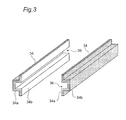
- Fig. 3 is a perspective view illustrating the heat-insulating members of the heating cooker according to the first embodiment.
- Fig. 4 is a perspective view schematically illustrating directions of coil current running through the coils of Fig. 2 , and directions of induction current running through the heaters.
- Fig. 5 is a partial enlarged cross sectional view of the induction-heating means according to the first embodiment.
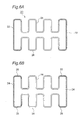
- Figs. 6A and 6B are plan views illustrating the heater of the heating cooker according to the first embodiment, in a structural and functional manner, respectively.
- Fig. 7 is a cross sectional view of the heating cooker according to modification of the first embodiment, as similar to Fig. 1 .
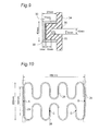
- Fig. 8 is an enlarged cross sectional view of the induction-heating means according to modification of the first embodiment, as similar to Fig. 5 .
- Fig. 9 is a cross sectional view of the induction-heating means used in an experiment of the first embodiment.
- Fig. 10 is a plan view of the induction-heating means used in an experiment of the first embodiment, showing several measurement points of the heater.
- Fig. 11 is a graph showing increased temperature measured at each of the measurement points of the heater in the experiment.
- Fig. 12 is a cross sectional view of the heating cooker according to the second embodiment of the present invention.
- Fig. 13 is a perspective view illustrating an overall of main components of the heating cooker according to the second embodiment.
- Fig. 14 is a graph showing increased temperature of the heater measured in the experiment according to the second embodiment.
- Fig. 15 is a cross sectional view of the heating cooker according to modification of the second embodiment.
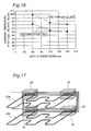
- Fig. 16 is a chart showing a relationship between increased temperature of the heater and length of the magnetic member according to modification of the second embodiment.
- Fig. 17 is a perspective view illustrating an overall of main components of the heating cooker according to further modification of the second embodiment.
- Fig. 18 is a cross sectional view of the heating cooker according to the third embodiment of the present invention.
- Fig. 19 is a perspective view illustrating an overall of main components of the heating cooker according to the third embodiment.
- Fig. 20 is a partial enlarged cross sectional view of the induction-heating means according to the third embodiment.
- Fig. 21 is an enlarged cross sectional view of the induction-heating means according to modification of the third embodiment as similar to Fig. 20 .
- Fig. 22 is an enlarged cross sectional view of the induction-heating means according to further modification of the third embodiment as similar to Fig. 20 .
- Fig. 23 is a cross sectional view of the heating cooker according to the fourth embodiment of the present invention.
- Fig. 24 is a perspective view illustrating an overall of main components of the heating cooker according to the fourth embodiment.
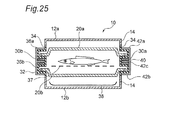
- Fig. 25 is a cross sectional view of the heating cooker according to modification of the fourth embodiment.
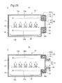
- Figs. 26A and 26B are cross sectional views of the heating cooker according to the fifth embodiment, with the movable component being in closed and opened positions to the stationary component, respectively.
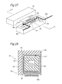
- Fig. 27 is a perspective view illustrating the induction-heating means according to the fifth embodiment.
- Fig. 28 is an enlarged cross sectional view of the induction-heating means according to the fifth embodiment, taken along a line of A-A of Fig. 27 .
- Fig. 29 is a cross sectional view of the heating cooker according to the sixth embodiment of the present invention.
- Fig. 30 is a perspective view illustrating an overall of main components of the heating cooker according to the sixth embodiment.
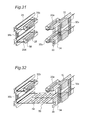
- Fig. 31 is a perspective view illustrating an overall of main components of the heating cooker according to modification of the sixth embodiment.
- Fig. 32 is a perspective view illustrating an overall of main components of the heating cooker according to further modification of the sixth embodiment.
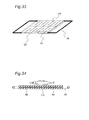
- Fig. 33 is a perspective view of an overall of the plate-like lower heater according to further modification of the sixth embodiment.
- Fig. 34 is a cross sectional view of the plate-like lower heater of Fig. 33 .
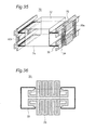
- Fig. 35 is a perspective view illustrating an overall of main components of the heating cooker according to further modification of the sixth embodiment.
- Fig. 36 is a development view of the heater of the heating cooker of Fig. 35 .
- Fig. 37 is a cross sectional view of the heater of the heating cooker of Fig. 35 .
- Fig. 38 is a cross sectional view illustrating an overall of main components of the heating cooker according to further modification of the sixth embodiment.
- Fig. 39 is a cross sectional view illustrating an overall of main components of the heating cooker according to further modification of the sixth embodiment.
- heating cooker heating system
- 10 heating chamber (box-shaped housing)
- 12a upper wall
- 12b lower wall
- 16 front wall
- 18 rear wall
- 20 heater
- 22 low-resistive part
- 24 power-supplied part
- 25 cooling part
- 26 high-resistive part (heating part)
- 30 coil
- 32 magnetic member
- 34 heat-insulating member
- 36 groove (opening)
- 37 grid
- 38 fat-receiving dish
- 40 base portion
- 42 side portion
- 44 extended portion
- 45 heat-insulating member
- 50 stationary component
- 54 heater-access port
- 56 airtight case
- 58 lower heater
- 59 cutout
- 70 box-shaped airtight container
- 72 lid member
- 74 container member
- 75 container body
- ⁇ 1, ⁇ 2 magnetic flux.
- the present invention relates to any types of heating systems and may be applicable even for an industrial firing furnace and drying furnace, and a household cooker as well.
- a cooker as an example of the heating system according to the present invention will be described herein.
- a couple of terms for indicating the directions (for example, “upper”, “lower”, “left” and “right”, etc.) are conveniently used just for facilitating clear understandings, it should not be interpreted that those terms limit the scope of the present invention.
- Similar components are denoted with similar reference numerals throughout the description.
- Fig. 1 is a cross sectional view of the heating cooker 1 according to the first embodiment
- Fig. 2 is a perspective view schematically illustrating an overall of main components of the heating cooker of Fig. 1 .
- the heating cooker 1 is suitably used for an IH cooking heater, especially useful as a heating chamber for grill-cooking.
- the present invention may also be adapted for any other types of heating cookers such as a microwave oven and/or a toaster oven, which is used for various cookeries such as oven-cooking, as well as grill-cooking.
- the heating cooker 1 includes a heating chamber (box-shaped housing) 10 as illustrated in Figs. 1, 2 .
- the heating chamber 10 includes upper and lower walls 12a, 12b, right and left side walls 14a, 14b extending vertically, and front and rear side walls (not shown).
- the heating cooker 1 includes detachable heaters 20a, 20b formed of metal in a closed loop (in a closed electrical circuit) provided within the heating chamber 10 near to the upper and lower walls 12a, 12b. It also includes coils 30a, 30b provided along the right and left side walls 14a, 14b of the heating chamber 10, and a pair of magnetic members 32 of magnetic material such as ferrite core provided along and adjacent the coils 30a, 30b.
- Each of the coils 30a, 30b may be formed, for example, by twisting a plurality (nineteen) of copper wires having diameter of 0.3mm coated with resin wire (so called a litz wire), and by winding the litz wire a plurality of times (25 times) in parallel with the side walls 14a, 14b in a rectangular shape each of which corner is bent in a right curved or an elliptic shape.
- litz wire wound along the sides of the rectangular shape of the coil current (magnetic flux) runs through the same direction.
- each of the magnetic members 32 is formed in a U-shaped so as to cover or surround the litz wires, and is arranged to oppose the upper and lower heaters 20a, 20b.
- the magnetic members 32 may be made of magnetic material similar to one generally used as the ferrite core around the heating coil of a typical IH cooking heater. Also, a plurality of U-shaped heat-insulating members 34 are provided inside each of the U-shaped magnetic members 32. Thus, the coils 30a, 30b are intervened between the magnetic members 32 and the heat-insulating members 34 at least in portions where the coils oppose to the heaters 20a, 20b, as illustrated in Figs. 1 and 2 . Furthermore, the heat-insulating members 34 may have a double-layered structure having a heat-insulating layer 34a made of glass wool or ceramic wool and a ceramics layer 34b as shown in Fig. 3 , and a portion of the side walls 14a, 14b of the heating chamber 10 may be formed of ceramics or metal such as iron and stainless steel.
- the heat-insulating members 34 so structured thermally insulates the coils 30a, 30b and the magnetic members 32 from hot atmosphere within the heating chamber 10.
- the insulating layer 34a is formed as air gap or air stream.
- Portions of he side walls 14a, 14b may be composed of the heat-insulating members 34 and the magnetic members 32 together with the coils 30a, 30b as illustrated in Fig. 1 .
- the other portions of the walls composing the heating chamber 10 e.g., upper and lower walls 12a, 12b
- the heating chamber 10 is defined also by the front and rear walls.
- the heating chamber 10 is formed as a closed box or housing from the upper and lower walls 12a, 12b, side walls 14a, 14b, and the front and rear walls.
- the front wall has a front door (not shown) that can be opened and closed for accessing food inside the heating chamber 10.
- the heaters 20a, 20b are inserted and supported within grooves (openings) 36 of the heat-insulating members 34, each of which extends horizontally as shown in drawings.
- the heaters 20a, 20b are merely situated or seated on the grooves 36, which allows the heaters to be detachable from the front door.
- this structure of the heating chamber 10 allows both of a grid 37 for supporting food and a fat-receiving dish 38 for receiving food fat to be inserted in and/or detached from the heating chamber 10 through the front door.
- the grid 37 and the fat-receiving dish 38 may be made of material and be structured in any configurations used in the heating chamber 10 of a conventional IH cooking heater.
- the side walls 14a, 14b and the other walls of the heating chamber 10 may preferably have inner surfaces coated with suitable material for various purposes realizing an antifoulant effect and an infrared-ray effect.
- the operation of the heating cooker 1 will be described herein.
- the high-frequency current having frequency in a range of 20kHz through 100kHz is supplied with coils 30a, 30b from a power circuitry (not shown)
- a high-frequency magnetic field is generated by and around the coils 30a, 30b.
- the high-frequency magnetic flux generated by the coils 30a, 30b defines a magnetic loop running through the U-shaped magnetic members 32, the heaters 20a, 20b, and the grooves (openings) 36 of the heat-insulating members 34.
- the heaters 20a, 20b magnetically interlinks with the high-frequency magnetic flux.
- induction current is generated through each of the heaters 20a, 20b that is electrically closed or formed as a loop, and then Joule heat is to generated by the induction current, so that the heaters 20a, 20b are heated entirely and uniformly.
- the heaters 20a, 20b heats the food received within heating chamber 10 in an even manner.
- the power circuitry supplies sufficient power (e.g., 2kW in total) with the coils 30a, 30b
- the heaters 20a, 20b are heated over 800 degrees C, from which infrared energy is radiated to directly heat the food.
- the heaters 20a, 20b heats peripheral atmosphere which is distributed by convection throughout the heating chamber 10, and then indirectly heats the food in hot atmosphere.
- the food within the heating chamber 10 is heated by infrared radiation and hot atmosphere, for grill-cooking.
- Fat flowing from the food to be heated is received by a fat-receiving dish 38 provided beneath the lower heater 20b.
- the induction current runs through the looped lower heater 20b, thereby generating Joule heat.
- This is the heating principle different from that of the conventional heating cooker as disclosed in the above Patent Documents 1, 2, where the magnetic body is directly induction-heated. Therefore, even if the fat-receiving dish 38 is made of metal and arranged beneath the lower heater 20b, it is not directly induction-heated by the lower heater 20b, and therefore, the fat-receiving dish 38 can be kept at temperature much lower than the kindling temperature of the fat, by spacing the gap between the lower heater 20b and the fat-receiving dish 38.
- the heating principle utilizing Joule heat generated by the induction current running through the looped heater is different from the "induction--heating" " principle for pans seated on the top plate of a typical IH cooking heater, and thus, the heating principle the present invention may not be referred to as the "induction-heating".
- the present invention utilizes Joule heat generated by the "induction current” running through the looped heater caused by the "electromagnetic induction”
- this application will also uses the term of the "induction-heating” herein.
- the coils 30a, 30b and the magnetic members 32 are collectively referred to as “induction-heating means" for generating induction current through the heaters 20a, 20b.
- the temperature and the input power of the heaters 20a, 20b are indicated above as an example, and the temperature of the heaters 20a, 20b may be determined by parameters including the input power and the radiation surface area thereof, etc.
- any types of power circuitries may be incorporated which are similar to ones used in a typical induction-heating cooker such as a IH cooker, including, for example, a half-bridge circuitry, a full-bridge circuitry, and an one-oscillator circuitry.
- a half-bridge circuitry As easily be configured for a person skilled in the art without further description of the power circuitry in the embodiments, an oscillating capacitance is connected with the coil in series used in the half-bridge circuitry and the full-bridge circuitry, and in parallel used in the one-oscillator circuitry. This is well known in the art, and therefore is also adapted in other embodiments according to the present invention.
- each of the coils 30a, 30b is supplied with power individually from the respective one of the power circuitries, or the coils 30a, 30b connected in parallel or series with each other may be supplied with power from the same the power circuitry.
- the coils 30a, 30b are connected in parallel or in series with each other, attention should be paid for connection thereof, taking into consideration of current flow direction, which will be discussed more hereinafter.
- Fig. 4 illustrates directions of coil current running through the coils 30a, 30b, directions of magnetic flux generated by coil current, and directions of induction current running through the heaters 20a, 20b induced by electromagnetic induction.
- all of components except the coils 30a, 30b and the heaters 20a, 20b are eliminated.
- flow directions of the coil current and the induction current are traced over the coils 30a, 30b and the heaters 20a, 20b.
- the coil current and the induction current have flow directions alternated at driving frequency, and Fig. 4 is illustrated at a certain moment of the flow directions. As illustrated in Fig.
- the coil current through the coils 30a, 30b generates the magnetic flux around the coils 30a, 30b with which heaters 20a, 20b magnetically interlink, thereby developing electromotive force and generating the induction current through the heaters 20a, 20b formed in a closed loop.
- this mechanism is the same as one of a transformer, in which the coils 30a, 30b may be regarded as being equivalent to primary coils, and so the heaters 20a, 20b being as secondary coils of the transformer.
- the heaters 20a, 20b are heated by using such mechanism, when the coils 30a, 30b connected in series or in parallel are driven by a single power circuitry, the coils 30a, 30b should be connected so as to allow the coil current running as shown in Fig. 4 .
- the phase (or direction) of the coil current through the coils 30a, 30b may be adjusted for obtaining any desired (or controllable) heating efficiency, and may be set optimal for realizing the most heating efficiency when the phase (or direction) is controlled as shown in Fig. 4 .
- Fig. 5 is an enlarged cross sectional view of one of four induction-heating means of the heating cooker 1 in Fig. 1 , which includes the coil 30 and the magnetic member 32 (together with the heat-insulating members 34 and the heater 20).
- the heater 20 is illustrated only for a portion which magnetically interlinks with the magnetic flux.
- the high-frequency current runs through the coil 30, the high-frequency magnetic flux is generated around the coil 30.
- the high-frequency magnetic flux runs through a magnetic circuit (loop) which penetrates the U-shaped magnetic member 32 and transverses the U-shaped opening thereof.
- the "U-shaped magnetic member 32" is defined as including a base portion 40 extending along the coil 30, and a pair of side portions 42a, 42b extending perpendicularly to the base portion 40 from ends thereof, between which the opening 36 is formed.
- the magnetic flux extending across the opening 36 of the U-shaped magnetic member 32 includes one ( ⁇ 1) that does not pass through the heater 20 and another one ( ⁇ 2) that penetrate the heater 20. While the magnetic flux ( ⁇ 1) is quite effective in generating the induction current through the electrically looped heater 20, the magnetic flux ( ⁇ 2) is less effective because its magnetic energy is used mostly for generating eddy current within the portion where the magnetic flux is penetrated but few for generating the induction current throughout the looped heater 20. Thus, the heater 20 is heated by Joule heat caused by the induction current and the eddy current as well.
- the heater 20 since the heater 20 is made of uniform material and shaped as having the same section along its extending direction, in general, it has higher temperature at portions which are closer to and magnetically interlinked with the coils 30a, 30b, and lower temperature at the other portions.
- the magnetic energy of the magnetic flux ( ⁇ 2) closer to the coils 30a, 30b also contributes heating atmosphere within the heating chamber 10 without energy loss, however, this requires further improvement of thermal insulation between the coil 30 (and the magnetic member 32) and the heater 20, by providing air gap for circulating air therethrough and/or by designing the heat-insulating member 34 thicker for thermally protecting the coil 30.
- Figs. 6A and 6B are plan views of the heater 20 suitably used in the heating cooker 1 of the first embodiment.
- the heater 20 is illustrated structurally in Fig. 6A and functionally in Fig. 6B .
- the heater 20 used for the heating cooker 1 of the present invention is not limited thereto, and may be formed in any shape and configuration with any material as far as being shaped in an electrically closed loop.
- the heater 20 may be composed of two parts structurally different from each other. That is, the heater 20 may include low-resistive parts 22 having lower electrical resistance at the end regions adjacent the coils 30a, 30b, and high-resistive parts 26 having higher electrical resistance in the middle thereof.
- the terms, i.e., the "low-resistive" part and the "high-resistive” part are intended as having lower or higher electrical resistance per unit length relative to each other.
- the low-resistive part 22 and the high-resistive part 26 may be formed from a solid bar and a hollow pipe, respectively, and may be connected, e.g., by welding each other.
- the low-resistive part 22 may be made of lower specific resistance such as copper and the high-resistive part 26 may be made of higher specific resistance such as stainless steel.
- the low-resistive part 22 and the high-resistive part 26 may have structure and material different from each other.
- the low-resistive part 22 may be made from a solid bar of copper or copper alloy having diameter of 6mm
- the high-resistive part 26 may be made of hollow pipe of stainless steel having diameter of 6mm and radial thickness in a range between 0.3mm through 1mm, which are connected together by welding or gluing.
- the hollow bar may possibly have the specific resistance less than that of the solid due to the skin effect, and if this is the case, the low-resistive part 22 may be made of hollow pipe.
- the heater 20 includes no electrical core like a heating wire of a sheath-heater, the heater 20 may be formed in any configuration as shown in Figs. 6A and 6B at a reasonable cost without damage by being folded. Furthermore, the heater so structured may be coated with various material for antifouling and/or protecting effect.
- the heater 20 will be described in a functional aspect herein.
- the low-resistive part 22 shown in Fig. 6B is composed of a power-supplied part 24 and a cooling part 25.
- the high-resistive part 26 shown in Fig. 6A is also referred to as a heating part 26.
- the heater 20 includes the low-resistive part 22 composed of the power-supplied part 24 and the cooling part 25 both made of a solid copper bar, and the high-resistive part (heating part) 26 of a stainless pipe. As illustrated in Figs. 1 and 2 , the heater 20 is inserted into the grooves (openings) 36 of the heat-insulating members 34 and situated within the heating chamber 10.
- the coil 30 When the coil 30 is supplied with high-frequency current by the power circuitry, high-frequency magnetic flux is generated around the coil 30, which magnetically interlinks with the power-supplied part 24 so as to generate induction current through the heater 20.
- the power-supplied part 24 is heated in response to Joule heat caused by induction current and eddy current, as it has relative lower resistance, less Joule heat by the induction current is generated therein. Also, as the power-supplied part 24 is made of material having relative low resistance, such as nonmagnetic metal (e.g., copper), it is possible to sufficiently reduce Joule heat by the eddy current.
- nonmagnetic metal e.g., copper
- the power-supplied part 24 Since the power-supplied part 24 is situated within or surrounded by the groove 36 of the heat-insulating member 34, it is less cooled than the cooling part 25.
- the cooling part 25 has the same structure and construction material as the power-supplied part 24, since the cooling part 25 is surrounded by air, it is much more cooled than the power-supplied part 24. Also, the cooling part 25 is made of material having less resistance, Joule heat by induction current is reduced and kept at relative lower temperature.
- the heating part 26 is overall exposed in the air, it is cooled equally as the cooling part 25, however, since the heating part 26 has greater electronic resistance, it generates more Joule heat by induction current than the cooling part 25. Therefore, the food within the heating chamber is efficiently heated and grilled by radiation heat from the heating part 26. Also, the cooling part 25 generates less heat and radiates more heat transferred from the heating part 26 to peripheral air, which minimizes the heat that is generated by the heating part 26 and transferred through the cooling part 25 to the power-supplied part 24, thereby keeping the power-supplied part 24 at lower temperature.
- the magnetic member 32 defining the magnetic loop (magnetic circuit).
- the high-frequency current through the coil 30 generates the high-frequency magnetic flux around the coil 30 which defines the magnetic circuit running through the U-shaped magnetic member 32 and across the opening 36.
- both of the magnetic flux generate induction current running through the heater 20.
- the magnetic flux ( ⁇ 1) is increased as much as possible.
- Fig. 7 is a cross sectional view of an improved heating cooker 1, which is generally similar to that as illustrated in Fig. 1 , except that the magnetic member 32 has a different shape and/or configuration.
- Fig. 8 is an enlarged cross sectional view of a portion of the induction-heating means, similar to Fig. 5 , which includes the coil 30, the magnetic member 32, the heat-insulating members 34, and the heater 20.
- the magnetic member 32 of Fig. 8 is basically the same as that of Fig. 5 except its shape and/or configuration so that the magnetic member 32 is improved to increase a ratio ( ⁇ 1/ ⁇ 2) of the magnetic flux.
- the magnetic member 32 of Fig. 5 has a U-shaped cross section
- the magnetic member 32 of Figs. 7 and 8 has a C-shaped cross section.
- the "C-shaped magnetic member” are intended as one including a base portion 40 extending along the coil 30, a pair of side portions 42a, 42b extending perpendicularly to the base portion 40 from the ends thereof, and a pair of extended portions 44a, 44b extending from tips of the side portions 42a, 42b towards each other, between which the opening 36 is formed.
- the magnetic member 32 of Fig. 8 has a cross section which has a rectangular shape having one member partially opened or broken in its middle.
- the magnetic member 32 may have a trapezium or oval shape rather than the rectangular shape.
- the C-shaped magnetic member 32 reduces magnetic resistance of the magnetic flux ( ⁇ 1), thereby increasing the magnetic flux ( ⁇ 1) between the extended portions 44a, 44b and reducing the magnetic flux ( ⁇ 2). Therefore, the C-shaped magnetic member 32 of Figs. 7 and 8 reduces Joule heat by eddy current within the power-supplied part 24 of the heater 20, in comparison with the U--shaped magnetic member 32 of Fig. 5 .
- the C-shaped magnetic member 32 requires greater volume of construction material than the U-shaped magnetic member 32, and therefore, raises manufacturing cost of the C-shaped magnetic member 32.
- the power-supplied part 24 and the heating part 26 of the heater 20 may not necessarily be structured or formed in a different manner, so that the manufacturing cost of the heater 20 is substantially reduced.
- the manufacturing cost upon taking consideration of the other design factors such as the manufacturing cost, it is to be determined whether the U-shaped or C-shaped magnetic member 32 is incorporated.
- the C-shaped magnetic member 32 has the smaller opening 36 (less distance between the extended parts 44a, 44b), and it is ultimately or most desirable that the distance between the extended parts is zero and the magnetic member 32 has an O-shaped cross section.
- the heater 20 may be formed from a metal plate instead of a bar or pipe having a circular cross section.
- the heater 20 made of non-magnetic stainless steel plate having thickness of 2mm may cause the opening 36 (the distance between the extended parts) of the C-shaped magnetic member 32 to be smaller by 4mm.
- Fig. 9 is a cross sectional view of the induction-heating means of the heating chamber 10 used in the experiment, in which the scale size thereof was almost precisely duplicated as actually used one.
- the magnetic member 32 has the C-shaped cross section as shown in Fig.
- the magnetic member 32 is made from ferrite core and has thickness of 5mm.
- the heat-insulating member 34 is made of ceramic wool and has thickness of 10mm.
- the coil 30 was formed by 25 times winding the litz wire of nineteen of twisted copper wires having diameter of 0.3mm coated with resin wire.
- the coils 30a, 30b provided at left and right side walls of the heating chamber 10 as shown in Fig. 2 , were connected in parallel and supplied with the high-frequency current of 25kHz from a half-bridge power circuitry.
- the heater 20 has a circular cross section having diameter of 6mm. As seen from Fig.
- Fig. 10 shows the structure of the heater 20 used in the experiment, in which the scale size thereof was almost precisely duplicated as actually used one.
- the heater 20 was made to have two different types of material and configuration also as shown in Fig. 6 .
- the low-resistive part 22 was made from a bar of copper having diameter of 6mm and the high-resistive part 26 was made from a hollow pipe of non-magnetic stainless steel SUS 304, which has outer diameter of 6mm, inner diameter of 4mm, and radial thickness of 1mm.
- the copper bar (low-resistive part 22) and the stainless pipe (high-resistive part 26) were connected by gold soldering.
- a pair of portions as shown by left and right dashed rectangles in Fig. 10 is inserted in the grooves 36 of the heat-insulating members 34 when situated within the heating chamber 10.
- the heater 20 so structured includes no cooling part 25 as shown in Fig. 6B .
- Several points where the thermoelectric couples were provided for thermal measurements are indicated by solid circles A-D on the heater 20 of Fig. 10 .
- the thermoelectric couples were attached by winding a Kapton tape on those points. Because of the thermally resisting limit of the Kapton tape, the temperature was measured in a range less than 400 degrees C.
- Fig. 11 is a graph showing temperature detected at each of the temperature measurement points of the heater 20 when the power circuitry is supplied with power of 1kW.
- the temperature measurement were made on the upper heater 20a at the points A, B, C, D in Fig. 10 , and on the lower heater 20b at the points A, B, C.
- the denotation of "power-supplied parts" in Fig. 11 indicates the temperature detected at the points A, B, and the denotation of "heating parts” in Fig. 11 indicates the temperature detected at the points C, D.
- Temperature on the upper and lower heaters 20a, 20b detected at each of the points are approximately the same as one another, those measurements are plotted in Fig. 11 without distinguishing the upper or lower heater 20a, 20b.
- the heating cooker 1 having the heater 20 of Fig. 2 is used for heating and cooking food. Since the heating part 26 of the heater 20 at each measurement point has approximately the same temperature, it is clear that the heating part 26 is heated by Joule heat caused by induction current running throughout the looped heater 20. The thermal increase rate of the heating part 26 is substantial, which is partially because of less heat capacity of the heating part 26 made of a stainless pipe. For example, two minutes after initiating heating, the temperature of the heating parts 26 is rather higher than that of the power-supplied parts 24, which also clearly shows that the heating parts 26 are heated by itself and not by the heat transferred from the power-supplied parts 24.
- the present invention looks similar to aforementioned Patent Document 3 in view that the magnetic cores are used for applying the high-frequency magnetic flux through the side walls, but is totally different from it in view of the heating mechanism.
- Patent Document 3 only the side portions of the oven dish are magnetically interlinked with magnetic flux to be induction-heated by induction current running therethrough.
- the overall of the heater 20 rather than only the power-supplied parts 24 of the heater 20 is induction-heated by induction current running throughout the looped heater 20, which is caused by the high-frequency magnetic flux passing by (not penetrating through) the power-supplied parts 24 of the heater 20.
- the temperature of the power-supplied part 24 increases moderately but eventually more than that of the heating part 26. This is partially because the power-supplied part 24 is heated by eddy current generated by magnetic flux running through the power-supplied part 24. This is also because a portion of the heating part 26 connected with the power-supplied part 24 is received in the groove 36 of the heat-insulating member 34 as shown in Fig. 10 so that the portion of the heating part 26 radiates thermal energy less than the other portions (at measurement points C, D), thereby raising the temperature thereof. Heat from the raised portion of the heating part 26 is transferred to the power-supplied part 24 which also radiates less thermal energy, which may make the temperature of the power-supplied part 24 higher.
- the cooling part 25 as shown in Fig. 6B in order to lower the temperature of the power-supplied part 24. It may be needless to mention that while the temperature of the heating part 26 in the experiment of Fig. 11 is relatively low for grill-cooking, the temperature of the heating chamber 10 can be raised by providing the upper wall 12a and the front wall thereof and by supplying with greater power, which is suitable for grill-cooking.
- the heating chamber 10 of the heating cooker 1 of Figs. 1 and 2 may include the side walls 14a, 14b made of metal such as iron plate, which may also be induction-heated by the magnetic flux generated by the coils 30a, 30b, as well as the magnetic members 32. Yet, the induction-heated side walls may efficiently raise the temperature of air within the heating chamber 10.
- the heating cooker 1 includes the induction-heating means on the side walls 14a, 14b of the heating chamber 10. Also, the heating cooker 1 includes the electrically looped heaters 20a, 20b which are detachably arranged within the heating chamber 10 and overall heated by induction current generated by high-frequency magnetic flux from the side wallsl4a, 14b. This allows the heating chamber 10 more easily cleaned and the fat-receiving dish 38 of metal positioned beneath and spaced enough from the lower heater 20b.
- Fig. 12 is a cross sectional view of the heating cooker 1 according to the second embodiment of the present invention
- Fig. 13 is a perspective view schematically illustrating an overall of main components of the heating cooker of Fig. 12 .
- the induction-heating cooker 1 of the second embodiment is similar to one of the first embodiment except that only one coil is provided on the side wall 14 for supplying the high-frequency magnetic flux with the heater 20 formed in an electrical loop. Therefore, the duplicated description in detail for the common features will be eliminated. Similar components are denoted with similar reference numerals throughout the description.
- the heating chamber 1 of the heating cooker 1 according to the second embodiment includes only one induction--heating means.
- the heater magnetically interlinks with the high-frequency magnetic flux generated by electromagnetic induction, so that induction current runs through the heater formed in an electrical loop. Therefore, the second embodiment will be described as including one induction-heating means having one set of a coil and other components, while possibly having two sets as the first embodiment, or having three or more sets thereof. Also, what is described for the first embodiment may naturally be applicable for the heating cooker 1 according to the second embodiment.
- the heating chamber 10 includes the left side wall 14b having grooves 39 for supporting the heaters 20a, 20b but no coil 30 provided thereon.
- the side wall 14b may be formed of metal material such as iron, in which at least one of the side wall 14b and heaters 20a, 20b should be coated with insulating material for electrical insulation between both of the heaters 20a, 20b,
- the inner walls of the heating chamber 10 and the heaters 20a, 20b are coated with material for antifouling, protecting and/or far-infrared effects, therefore, such a coating may be adapted also for electrical insulation effect.
- Fig. 14 is a graph showing the measured temperature of the heater 20 of the heating chamber 10 shown in Fig. 13 .
- the driving condition of the induction-heating cooker 1 of the second embodiment is similar to one of the first embodiment except that a single induction-heating means is used.
- the input power was 500W.
- the power-supplied parts 24 had temperature greater than the heating parts 26. Since the upper and lower heating parts 20a, 20b had the increased temperature different from one another in this experimental result, each of measurement was individually plotted in Fig. 14 .
- the temperature of the upper and lower heaters 20a, 20b is different from each other, which is understood because each of them has different position or relationship against the induction-heating means and the lower heater is supplied with greater power.
- the heating parts 26 had the temperature saturated after about six minutes passed, but the power-supplied parts 24 have the temperature kept further increasing thereafter. This is understood because the temperature of the heating parts 26 is increased by its own heat rather than by heat transferred from the power-supplied parts 24.
- the heating cooker when the heating cooker is designed to have a single induction-heating means having the coil 30 and other components, more amount of heat is generated in the power-supplied parts 24, therefore, it is useful to form the magnetic member in the C-shape as described in the first embodiment so as to increase magnetic flux passing by (not penetrating through) the heater 20 and reduce penetrating magnetic flux magnetically interlinked with the heater 20. This can suppress increased temperature of the power-supplied parts 24 and increase the temperature of heating parts 26 even when the heater 20 has one power-supplied part 24.
- the heater 20 is provided with one power-supplied part 24, that is, when one induction-heating means is required, the manufacturing cost is advantageously reduced.
- Fig. 15 is a cross sectional view of the heating cooker 1 including the induction-heating means arranged on the rear wall 18.
- the magnetic member has the C-shaped cross section so as to suppress increased temperature of the power-supplied parts 24.
- the front wall 16 of the housing (the heating chamber 10) may be structured to be opened and closed, and be partially composed of a front door 17 made of glass through which the inside thereof can be observed during cooking.
- the heating principle of the induction-heating means arranged on the rear wall 18 is similar to that on the side wall 14 as described in the above embodiments.
- the heater 20 having two of the low-resistive parts 22 in both ends thereof is used in this experiment, as illustrated in Figs. 6A, 6B , and 10 .
- the heater 20 allows a user to easily install it within the heating chamber 10 without paying attention to the direction thereof, which eliminates or alleviates user's complicated installation and prevents malfunctioning due to wrong direction installation (erroneous installation in direction) of the heater 20.
- Fig. 16 is a chart showing increased temperature of the heaters 20 which include one or two of the power-supplied parts 24 for comparison.
- the horizontal axis of Fig. 16 indicates length of the magnetic member 32, and the increased temperature of the magnetic member 32 having 60mm-long single power-supplied part 24 is obtained through the experiment of Fig. 14 , and the increased temperature of the magnetic member 32 having 60mm-long two power-supplied parts 24 are detected through the experiment of Fig. 11 .
- the structure of the heating chamber 10 and the driving conditions of the induction-heating means are the same as those of the first and second embodiments.
- the vertical axis of Fig. 16 indicates relative increased temperature when the increased temperature of the single 60mm-long power-supplied part 24 measured at 30 seconds after initiation of power supply.
- the input power to the induction-heating means is set as 500W with the single power--supplied part 24 and as 1kW with two power-supplied parts 24.
- either one the power-supplied parts 24 is supplied with power of 500W.
- the reason why the increased temperature is measured at 30 seconds after initiation of power supply is to compare the increased temperature of the power-supplied parts 24 when they are not too hot for reducing influence of the heat radiation. While two of the heaters 20a, 20b are provided, in case where each of them has two power-supplied parts 24, the increased temperature is plotted in Fig. 16 by averaging the temperature of the power-supplied parts 24.
- the increased temperature of the power-supplied part 24 with two of the power-supplied parts 24 is less than that with one of the power-supplied part 24. Also, as the magnetic member 32 is longer, the increased temperature of the power-supplied part 24 is lower, but is not proportional to the length thereof and almost saturated at the length of 120mm or greater in this experiment of Fig. 16 . Furthermore, the increased temperature of the power-supplied part 24 with two of the power-supplied parts 24 each having the length of 60mm is almost equal to that with one the power-supplied part 24 having the length of 120mm.
- each of two power-supplied parts 24 is heated with power of 500W as a solid line in Fig. 16 while single power-supplied part 24 is heated with power of 1kW as a dashed line, of which temperature is almost double of the former one.
- the magnetic member 32 has entire length equal as each other, one having two power-supplied parts 24 is more advantageous that one having single power-supplied part 24.
- the power--supplied part 24 is a power source and it is effective to provide more power sources in number for generating induction current through the heater.
- the magnetic member 32 having the C-shaped cross section advantageously suppresses the increased temperature of the power-supplied part 24 than that having U-shaped cross section.
- the heater 20 is provided with the single power-supplied part 24 only on either one of the side walls 14, the rear wall 18 and the front wall 16 of the heating chamber 10, the heating chamber 10 can be structured simply, designed with greater degree of freedom, and manufactured at a more reasonable cost.
- Fig. 17 is a perspective view schematically illustrating an overall of the heating cooker, including the heater 20 provided with two power--supplied parts 24 and the induction-heating means arranged on the rear wall 18 of the heating chamber 10.
- Fig. 17 also illustrates just main components of the heating cooker like Fig. 2 and eliminates the heat-insulating members 34 for clarity.
- the heating chamber 10 of Fig. 17 is also composed of the side wall 14 and others required for defining the heating chamber 10 as shown in Fig. 1 .
- Each of the heaters 20a, 20b is provided with two of the power-supplied parts 24 close to the rear wall 18 of the heating chamber 10.
- a single coil 30 is arranged outside the heating chamber 10 adjacent the rear wall 18 thereof, thus four of the U-shaped magnetic members 32 are provided in total along the coil 30.
- Each of the magnetic members 32 may be C-shaped as well.
- the coil 30 When supplied with high-frequency current, the coil 30 generates high-frequency magnetic flux with which heaters 20a, 20b magnetically interlink, thereby inducing current throughout the heaters by electromagnetic induction. Since each of the heaters 20a, 20b has two power-supplied parts 24, even with single coil provided along the rear wall 18, increased temperature of the power-supplied parts 24 can be suppressed, while keeping high temperature of the heating part 26.
- Fig. 18 is a cross sectional view of the heating cooker 1 according to the third embodiment of the present invention
- Fig. 19 is a perspective view illustrating an overall of main components of the heating cooker of Fig. 18
- the induction-heating cooker 1 of the third embodiment is similar to one of the first embodiment except that the coil 30 is formed by spirally winding a conductive wire around the magnetic member 32 so as to supply the high-frequency magnetic flux with the heater 20 formed in an electrical loop. Therefore, the duplicated description in detail for the common features will be eliminated. Similar components are denoted with similar reference numerals throughout the description.
- each of the coils 30a-30d is formed by a spirally winding a conductive wire such as a litz wire around the base portion 40 of the magnetic member 32 having the U-shaped configuration.
- a conductive wire such as a litz wire
- the other coils 30b, 30d are just invisible behind the heat-insulating members 34 but actually existed.
- Each of the coils 30a-30d may be supplied with high-frequency current by an individual power circuitry (not shown).
- a pair of the coils 30a, 30c and a pair of the coils 30b, 30d may be electrically connected in series or parallel to be supplied with high-frequency current by two of the power circuitries, respectively.
- a pair of the coils 30a, 30b and a pair of the coils 30c, 30d may be electrically connected in series or parallel to be supplied with high-frequency current by two of the power circuitries, respectively. Furthermore, all of the coils 30a-30d may be electrically connected in series or parallel to be supplied with high-frequency current by the single power circuitry.
- each of the coils 30a-30d are connected to induced current running throughout the heaters 20a, 20b in directions as shown in Fig. 4 of the first embodiment.
- the upper and lower heaters 20a, 20b may be separately heated, and therefore, each of the heaters 20a, 20b may be thermally controlled in an individual manner and/or either one of them may be driven for a desired cookery purpose.
- Figs. 20 and 21 are enlarged cross sectional views of the induction-heating means with the coil 30 generating magnetic flux according to the third embodiment.
- the magnetic members 32 of Figs. 20 and 21 have the U-shaped and C-shaped cross sections, respectively.
- the magnetic flux ( ⁇ 1, ⁇ 2) are generated by the coils 30 similarly as described in the first and second embodiments.
- the coils 30 according to the third embodiment may be replaced with ones as explained in the first and second embodiments, and also the technique in the first and second embodiments can equally be applied to the third embodiment.
- the coil 30 may be wound around another portion (e.g., the side portion 42 extending from the base portion 40) of the magnetic member 32 different from ones of Figs. 20 and 21 .
- Fig. 23 is a cross sectional view of the heating cooker 1 according to the fourth embodiment of the present invention
- Fig. 24 is a perspective view schematically illustrating an overall of main components of the heating cooker of Fig. 23 .
- the induction-heating cooker 1 of the fourth embodiment is similar to one of the first embodiment except that the coil 30 is formed by spirally winding a conductive wire around two of adjacent magnetic members 32 so as to supply the high-frequency magnetic flux with the heater 20 formed in an electrical loop. Therefore, the duplicated description in detail for the common features will be eliminated. Similar components are denoted with similar reference numerals throughout the description.
- each of the coils 30a, 30b is formed by a spirally winding a conductive wire such as a litz wire around the side portions 42 of two neighboring magnetic members 32 provided on the side wall of the heating chamber 10.
- the conductive wire of the fourth embodiment is spirally wound around the side portions 42 of the magnetic members 32 positioned on and along one of the side walls 14 of the heating chamber 10.
- Fig. 25 is a cross sectional view of the heating cooker 1 having a magnetic member 32 formed in a E-shaped configuration which seems like two of neighboring U-shaped magnetic members combined together.
- the magnetic member 32 of Fig. 25 has a base portion 40, a pair of side portions 42a, 42b extending perpendicularly to the base portion 40 from ends thereof, and a middle portion 42c extending from the middle thereof.
- the magnetic member 32 shown in Fig. 25 has two of grooves (openings) 36a, 36b between the middle portion 42c and each of the side portions 42a, 42b.
- the heaters 20a, 20b are inserted into the grooves 36a, 36b, respectively.
- the heating cooker 1 of Fig. 25 is substantially the same as that of Figs. 1 and 2 .
- the E-shaped magnetic member 32 is treated as combined magnetic member composed of two U-shaped magnetic members. Therefore, the E-shaped magnetic member 32 may have upper and lower portions each of which is C-shaped, and other features in its cross section as explained in the above embodiments.
- the planar coil of the first embodiment may be used together with the E-shaped magnetic member 32 of Fig 25 .
- FIGs. 26A and 26B are cross sectional views of the heating cooker 1 according to the fifth embodiment of the present invention.
- Fig. 27 is a perspective view and
- Fig. 28 is a cross sectional view showing the induction-heating means of the heating cooker according to the fifth embodiment.
- the induction-heating cooker 1 of the fifth embodiment is similar to one of the second embodiment except that it has another magnetic member 32 which can be assembled to surround the heater 20 entirely in its cross section. Therefore, the duplicated description in detail for the common features will be eliminated. Similar components are denoted with similar reference numerals throughout the description.
- the heating cooker 1 includes the magnetic member 32 formed in the U-shaped or C-shaped cross section, and the heaters 20 magnetically interlinked with magnetic flux including one ( ⁇ 1) that does not pass through the heater 20 and another ( ⁇ 2) that penetrate the heater 20. Also, the magnetic flux ( ⁇ 1) passing by (not penetrating through) the heater is more effective to generate Joule heat in the heating part of the heater 20 owing to reduction of heat by the eddy current within the power-supplied part 24 thereof. As will be described herein, the heating cooker 1 according to the fifth embodiment can maximize magnetic flux which dose not penetrate through the heater 20 and causes optimal magnetic interlinkage therewith.
- Figs. 26A and 26B illustrate the heating cooker 1 including the induction-heating means provided on the rear wall 18 of the heating chamber 10 as the second embodiment shown in Fig. 15 , yet the induction-heating means may be arranged on either one or both of the side walls 14 as described in other embodiments.
- the coil 30 is illustrated as being formed by spirally winding a conductive wire such as a litz wire, it may be formed by winding the conductive wire in a planer configuration as mentioned in the first and second embodiments.
- the heating cooker 1 of Fig. 26 includes the coil 30 and other components composing the induction-heating means, which are structured differently from the heating cooker 1 shown in Fig. 15 , but similarly to those of any embodiments in view of the other components.
- the coils 30a, 30b are made by spirally winding a conducting wire around a portion of the magnetic member 32 which is O-shaped and has no opening 36 in the cross section.
- the O-shaped magnetic member 32 is provided with the heat-insulating member 34 to prevent the magnetic member 32 and the coils 30a, 30b from being heated by the heaters 20a, 20b.
- another heat-insulating member 45 is provided around the O-shaped magnetic member 32 and along the inside wall of the heating chamber 10 in order to prevent the magnetic member 32 from being exposed in hot air within the heating chamber 10.
- the heat-insulating member 34 defines the inner groove 36 for receiving the power-supplied part 24 of the heater 20.
- the induction-heating means of the heating cooker 1 includes a stationary component 50 fixed with the heating chamber 10 and a movable component 52 designed as being slidable over the stationary component 50.
- the stationary component 50 includes the outer heat-insulating member 45, the coil 30, the U-shaped magnetic member 32, and the heat-insulating member 34 with the groove for receiving the power--supplied part 24 of the heater 20.
- the movable component 52 includes the outer heat-insulating member 45, the magnetic member 32 for defining a closed magnetic circuit ( ⁇ 1) in cooperation with the U-shaped magnetic member 32 of the stationary component 50, and the heat-insulating member 34.
- Fig. 26A illustrates the movable component 52 in the closed position ready for supplying induction current through the heaters 20a, 20b for heating.
- Fig. 26B illustrates the movable component 52 in the opened position allowing the heaters 20a, 20b detached from the heating chamber 10.
- the movable component 52 may be operated manually or automatically by means of mechanical means.
- Fig. 27 is a perspective view of the induction-heating means showing a concrete structure of the stationary component 50 and the movable component 52. While Fig. 27 illustrates the induction-heating means provided for the lower heater 20b, it may have a similar structure thereof for the upper heater 20a. Illustration is made especially focusing on the power-supplied part 24 of the heater 20b, which is formed in an electrically closed loop as described in the above embodiments. Fig. 27 illustrates the movable component 52 in the opened position over the stationary component 50. As illustrated, the magnetic member 32 of the stationary component 50 is surrounded by the heat-insulating member 34 and is exposed in a portion opposing to a bottom portion (not shown) of the movable component 52.
- the exposed portion of the magnetic member 32 may be coated with a thin protection film.
- the groove 36 provided inside the heat-insulating member 34 is a box-shaped, and when the movable component 52 is closed, the heating chamber 10 is designed to be thoroughly closed except a heater-access port 54. When the movable component 52 is closed, the heater access port 54 is structured to have a cross section conforming with the cross section of the heater 20. Also, when the power-supplied part 24 is inserted within the groove 36 and the movable component 52 is closed, the heating chamber 10 is formed to be sealed without interchanging air in the heating chamber 10 with air in the groove 36.
- blowing means for blowing outside air into the heating chamber 10 may be provided so as to cool inside the groove 36 or to increase pressure in the groove 36 higher than that in the heating chamber 10, thereby to prevent hot air from being introduced into the groove 36.
- Fig. 28 is an enlarged view of the magnetic flux generated by the induction-heating means of the heating cooker 1 of Fig. 26A, showing the lower heater 20b, especially the magnetic member 32 having the O-shaped cross section.
- most of the magnetic flux ( ⁇ 1) generated by the high-frequency current through the coil 30b runs through the O-shaped magnetic member 32. Therefore, most of the magnetic flux ( ⁇ 1) does not penetrate through the heater 20b, with which the heater 20b magnetically interlinks. As the result, the heater 20 is sufficiently heated by the induction current rather than the eddy current which is generated by the magnetic flux ( ⁇ 1).
- the detachable heater 20 with the magnetic member 32 having the O-shaped cross section
- the power-supplied part 24 of the heater 20 formed in an electrical closed loop may be arranged outside the heating chamber 10 and may be heated by induction current caused by the induction heating means having the O-shaped magnetic member 32.
- the heater 20 may have similar structure of a commonly used sheath heater for a conventional IH cooking heater.
- the sheath heater is composed of a ceramics sheath surrounding a heating core wire, which is inserted in a pipe of metal such as stainless steel, and therefore its structure is complicated.
- the conventional sheath heater has the heating core wire within the metal pipe, there is a restriction in curvature when bending it to have a desired shape. As more portions of the sheath heater are bent for the desired shape, it is more expensive to produce it. Furthermore, since the conventional sheath heater has ceramic sheath filled within the metal pipe, it has substantial heat capacity and requires much time to be well heated. On the other hand, since the heater 20 of the present invention can be made from a stainless steel pipe for example, it can be bent or curved more flexibly and more reasonably in comparison with the sheath heater. Also, when the heater 20 is made of metal pipe having less heat capacity, it can be heated more quickly than the sheath heater.
- the heater 20 with the U-shaped or C-shape magnetic member 32 of the present invention has several advantages over the conventional sheath heater as described in the above embodiments.
- the heater 20 of the present invention still has another merit that Joule heat generated by eddy current in the power-supplied part 24 can be minimized by means of the O-shaped magnetic member 32 as described in the fifth embodiment.
- the present embodiment describes the coil 30 formed by spirally winding a conductive wire around a portion of the magnetic member 32, the coil may be formed as similar ones illustrated in the first or fourth embodiment.
- Fig. 29 is a cross sectional view of the heating cooker 1 according to the sixth embodiment of the present invention
- Fig. 30 is a perspective view schematically illustrating an overall of main components of the heating cooker of Fig. 29 .
- the heating cooker 1 of the sixth embodiment is similar to one of the first embodiment except that the heaters 20a, 20b are provided along the side walls 14 so that the food within the heating chamber can be heated from the side surfaces. Therefore, the duplicated description in detail for the common features will be eliminated. Similar components are denoted with similar reference numerals throughout the description.
- the heating cooker 1 includes a heater 20 provided within the heating chamber 10 substantially along a horizontal direction
- the heating cooker 1 according to the sixth embodiment includes another type of the heater 20.
- the heating principle of the heater of the present embodiment is the same as aforementioned one, any one of the induction-heating means described in the above embodiments can be used in this embodiment as well.
- Fig. 31 is a perspective view illustrating main components having a heater 20 of the heating cooker 1 of modification according to the sixth embodiment.
- Each of the heaters 20a-20d shown in Fig. 31 has the power-supplied part 24 made from a solid metal bar having low resistance (e.g., a solid copper bar), and a heating part 28 made from a thin metal plate having high resistance and high fusing point (e.g., a thin tungsten plate).
- the heating part 28 is received within an airtight case 56 of quarts or translucent ceramics which is hermetically sealed and filled up with inert gas such as argon.
- the induction current runs through each of the heaters 20a-20d, so that the heating parts 28 are heated. Since the heating part 28 is made of metal having high fusing point and the airtight case 56 is filled up with inert gas, the heating part 28 can be heated up to high temperature in a range between 1000-2000 degrees C. This allows substantial amount of near-infrared and far-infrared radiation from the heating part 28, similar to an electrical light bulb such as a halogen lamp which generates substantial amount of light emission, heat, and infrared radiation. This radiation heating with infrared light makes the food grill-cooked.
- Fig. 32 is a perspective view illustrating main components including a heater 20 of the heating cooker 1 of further modification according to the sixth embodiment.
- the upper heaters 20a, 20b are the same as those shown in Fig. 31 .
- the lower heater 58 is made from a metal plate (e.g., a stainless steel plate) having thickness of approximately 2mm which has several cutouts 59 as illustrated in Fig. 32 .
- Each of the cutouts 59 may have a width enough for securing electrical insulation therein.
- the heating cooker 1 as structured in Fig. 32 is suitable for grill-cooking a hamburger steak, for example.
- each of the coils 30a, 30b is supplied with the high-frequency current so that it is heated by the upper heaters 20a, 20b and the lower heater 58.
- the lower heater 58 is heated up to approximately 200 degrees C to burn the hamburger steak like a frying pan.
- the fat coming from the food and falling down through the cutouts 59 is received onto a fat-receiving dish (not shown) arranged beneath the lower heater 58.
- each of the upper heaters 20a, 20b radiates infrared light for grill-cooking the hamburger steak.
- the lower heater 58 composing a high-resistive core member may be covered on its upper and lower surfaces with a cladding member 175 made of insulating material such as ceramics so as to keep the cutouts unexposed and form the lower heater 58 as a plate-like configuration.
- Fig. 33 is a perspective view of an overall of the plate-like lower heater 20 with the cutouts 59 unexposed
- Fig. 34 is a cross sectional view thereof.
- this lower heater 58 can be formed by covering (sandwiching or encompassing) the metal plate having the cutouts 59 with the cladding member 175 of insulation material such as ceramics.
- the cladding member 175 may be made of metal, another insulation material or coating is required for electrical insulation between the lower heater 58 and the cladding member 175.
- Fig. 35 is a perspective view illustrating main components including a heater 20 of the heating cooker 1 of even further modification according to the sixth embodiment.
- the heater 20 is housed within a box-shaped airtight container 70 having a lid member 72 and a container member 74.
- the box-shaped airtight container 70 performs as an oven or a kettle, and oven-cooking and oven-cooking of the food inside the box-shaped airtight container 70 can be achieved by heating the lid member 72 and the container member 74.
- Fig. 36 is a development view of the lower heater 20 housed in the container member 74, which is assembled to form the lower heater by bending up at dashed lines.
- the upper heater 20 of the lid member 72 is also assembled in a similar manner.
- the heater 20 includes the low-resistive parts 22 and the high-resistive part 26, in which each of the low-resistive parts has the power-supplied part and the cooling part as discussed in the above embodiments.
- the high-resistive part 26 is formed by punching a metal plate (e.g., stainless steel or aluminum plate) in a shape like Fig. 36 .
- Fig. 37 is a cross sectional view of the box-shaped airtight container 70.
- the lid member 72 includes a lid body 73 of insulation material such as ceramics and the high-resistive part 26, and the container member 74 also includes a container body 75 of insulation material and the high-resistive part 26 as well.
- the lid body 73 and the container body 75 may be made of metal. But if this is the case, since it is necessary to insulate the high-resistive part 26 from the lid body 73 and the container body 75, a thermal and electrical insulation film such as ceramic sheet should be interposed between the high-resistive part 26 and the lid body 73 (and the container body 75).
- a thermal and electrical insulation film such as ceramic sheet should be interposed between the high-resistive part 26 and the lid body 73 (and the container body 75).
- the lid body 73 and the container body 75 are made of aluminum, for example, they may be anode-oxidized (alumite-treatment) to form an alumina layer (an oxidized aluminum layer) on the surface thereof, thereby producing an insulating layer without preparing a separate insulating member at a reasonable cost.
- the heaters 20 provided within the lid body 73 and the container body 75 are heated by induction current therethrough, so that the food within the box-shaped airtight container 70 is heated and cooked.
- the heating cooker 1 is used as an oven, since the heated air within the box-shaped airtight container 70 is 300 degrees C or less which is less than the melting point of aluminum, the lid body 73 and the container body 75 can be produced of aluminum at a reasonable cost.
- Fig. 38 is a perspective view illustrating main components including a heater 20 of the heating cooker 1 of even further modification according to the sixth embodiment.
- the upper heater 20 is similar to that of Fig. 2
- the lower heater 58 is similar to that of Fig. 32 .
- the upper heater 20 may have the high resistive part made from a pipe (a hollow bar) since it is generally spaced from the food for cooking.
- the lower heater 58 may preferably have the high resistive part made from a metal plate having substantial surface area for uniform cooking.
- the upper and lower heaters may be have different configuration (shape, size, position) from each other, and may be designed as being detachable, therefore, any type of them may be chosen and replaced with another one in accordance with the food to be cooked.
- Fig. 39 is a cross sectional view illustrating a heating cooker 1 of even further modification according to the sixth embodiment.
- the induction-heating cooker 1 of Fig. 39 is similar to one of the third embodiment of Fig. 18 in structure and operation, except that the former has the coils 30a, 30b provided over the upper wall 12a and beneath the lower wall 12b rather than on the side walls 14a, 14b.
- the induction heating means with the coils 30 are described as being arranged on the side walls in the above embodiments, the present invention can equally be adapted to the induction heating means provided over the upper wall 12a and beneath the lower wall 12b as illustrated in Fig. 39 .
- the induction heating means may be provided on the front and rear walls, and the side walls may include the front and rear walls as well.
- the heater is structured as being detachable, therefore, the easy-to-clean feature is fairly improved and various types of the heaters 20 may be used appropriate for cooking purposes, thereby realizing a multifunctional heating cooker.
Landscapes
- Physics & Mathematics (AREA)
- Electromagnetism (AREA)
- Electric Stoves And Ranges (AREA)
- Induction Heating Cooking Devices (AREA)
- General Induction Heating (AREA)
Abstract
Description
- The present invention relates to a heating system, and in particular, relates to a heating cooker incorporating an induction current heater as a heat source in a heating box such as a heating oven, roaster, and grill.
- Many of heating cookers applying an electromagnetic induction heating principle, which are so-called IH (Induction-Heating) cookers, include, a heating box for cooking a grilled fish and the others. The heating box is generally named as a heating oven, roaster, or grill. A grilled fish (especially a saury grilled with salt, etc.) is popular when its surface is browned by radiation heat from burning heat source and its inside is well-heated within hot atmosphere.
- While cooking the grilled fish such as the grilled saury, substantial amount of fat (combustible oil) comes out of the grilled fish. Therefore, it is required to provide a dish for receiving the fat, and to keep the dish and the fish fat therein at temperature lower than kindling temperature thereof for preventing the fish fat from burning within the heating box during cooking. This is not limited to the grilled fish, it is true while cooking meat as well. Such cooking is also referred to as a grill-cooking.
- The heating box of the IH cooking heater is typically provided with upper and lower electrical heaters such as sheath heaters and radiant heaters, which may also be referred to as "resistive heaters" since they generate Joule heat when current flows through resistive elements. The electrical heaters are supplied with power through terminals electrically connected to a power source that is positioned outside the heating box, thereby generating Joule heat when electric power is supplied from the power source. The electrical heaters supplied with electric power transduce electric energy into thermal energy which heats and grills food to be cooked within the heating box directly and/or indirectly via heated atmosphere around the food. Such a heating cooker is incorporated not only within the IH cookers but also within a toaster oven and electric oven. While the heating cooker has a simple structure, it is difficult to clean inside the heating box because the electrical heaters are fixed within the heating box, and therefore it is required to improve the structure of the heating cooker to be more easily cleaned. Thus, in any types of heating systems including not only the IH cookers but also the heating ovens, the easy-to-clean feature is highly demanded, which is an essential demand for cookers of foods. In fact, many of heating ovens have been proposed so far, which has the heating source of metal for food which may be arranged within the heating box in a non-contact or induction manner, and/or detached from the heating box. [0005] For example, as disclosed in Patent Document 1 (
JP 2003-282221 A Patent Document 1, paragraphs [0008]-[0009] andFig. 2 . - Also, according to another microwave oven using the induction-heating technique as suggested in Patent Document 2 (
JP 08-138864 A Patent Document 2, paragraphs [0024]-[0028] andFigs. 1 ,3 . - Further another microwave oven using the induction-heating technique as suggested in Patent Document 3 (
JP 06-18044 A Figs. 1, 2 ,5-7 . - When the heating box or chamber using the above conventional induction-heating techniques is adapted into the IH cooking heaters for grill-cooking, a couple of following problems have been raised. In the conventional oven disclosed in
Patent Document 1, a U-shaped magnetic body is inserted within the heating box and heated by induction current through the upper and lower heating coils, and therefore, the lower surface of the magnetic body should be kept at temperature less than the kindling temperature (about 250 degrees C) of food fat (e.g., fish fat). Thus, since the lower surface of the magnetic body cannot be heated sufficiently, there is a problem that the oven is not suitable for grill-cooking by means of radiation. - In the conventional microwave oven disclosed in
Patent Document 2, since the metal band is formed in a closed loop, effective induction-heating is achieved up to high temperature. However, when infrared radiation heat from the metal band is used for grill-cooking, the fat-receiving separator is to be provided between the metal band and the heating coil. It should be designed to have the magnetic flux run through the metal band to be heated but not through the fat-receiving separator. Thus, the fat-receiving separator is required to be made of insulating material such as ceramics. Yet, the ceramic separator should be thick enough to ensure mechanical strength, and also be spaced away sufficiently from the metal band to keep temperature of the separator less than the kindling point of the fat so as to prevent fat on the separator from burning. Thus, it is necessary to keep substantial gap or distance between the metal band and the fat-receiving separator, which raises another problem that the metal band cannot be efficiently heated by the heating coil. - Furthermore, the microwave oven disclosed in Patent Document 3 may be used with the oven dish for a frying-pan cooking, but not suitable for the grill-cooking although the oven dish may possibly be heated to generate radiation heat for the grill-cooking. However, the heating coils of the microwave oven suggested by Patent Document 3 may heat only the peripheral portions of the oven dish, and thus, the middle or central portion thereof is merely heated indirectly by heat transferred from the peripheral portions of the oven dish, which is made of highly heat-conductive material such as aluminum and copper, Therefore, it is required to make the highly heat-conductive material fairly thick in order to sufficiently heat the central portion of the oven dish. This causes drawbacks, in turn, such as reduction of space of the heating chamber and increase of heat capacity of the oven dish requiring substantial time to heat the oven dish.
- The present invention addresses the above-mentioned drawbacks and has a purpose to realize a heating system which improves the easy-to-clean feature of the heating chamber with detachable heaters, and eliminates the problem of the food fat by arranging induction-heating means for heating the heaters outside the side walls of the heating chamber, also achieving substantially high temperature overall in the heating chamber.
- In order to overcome the above-described drawbacks, one embodiment of the present invention is to provide a heating system of the present invention comprises a box-shaped heating chamber, a heater provided inside the heating chamber, the heater being made of conductive material in an electrical loop, a coil provided outside the heating chamber, a power circuitry for supplying high-frequency current with the coil to generate high-frequency magnetic flux, and a magnetic member arranged so that the heater magnetically interlinks with the high-frequency magnetic flux generated by the coil.
- One embodiment of heating system according to the present invention generates induction current through a heater made of conductive material in an electrical loop, which generates Joule heat by induction current throughout the heater.
-
Fig. 1 is a cross sectional view of the heating cooker according to the first embodiment of the present invention. -
Fig. 2 is a perspective view illustrating an overall of main components of the heating cooker according to the first embodiment. -
Fig. 3 is a perspective view illustrating the heat-insulating members of the heating cooker according to the first embodiment. -
Fig. 4 is a perspective view schematically illustrating directions of coil current running through the coils ofFig. 2 , and directions of induction current running through the heaters. -
Fig. 5 is a partial enlarged cross sectional view of the induction-heating means according to the first embodiment. -
Figs. 6A and 6B are plan views illustrating the heater of the heating cooker according to the first embodiment, in a structural and functional manner, respectively. -
Fig. 7 is a cross sectional view of the heating cooker according to modification of the first embodiment, as similar toFig. 1 . -
Fig. 8 is an enlarged cross sectional view of the induction-heating means according to modification of the first embodiment, as similar toFig. 5 . -
Fig. 9 is a cross sectional view of the induction-heating means used in an experiment of the first embodiment. -
Fig. 10 is a plan view of the induction-heating means used in an experiment of the first embodiment, showing several measurement points of the heater. -
Fig. 11 is a graph showing increased temperature measured at each of the measurement points of the heater in the experiment. -
Fig. 12 is a cross sectional view of the heating cooker according to the second embodiment of the present invention. -
Fig. 13 is a perspective view illustrating an overall of main components of the heating cooker according to the second embodiment. -
Fig. 14 is a graph showing increased temperature of the heater measured in the experiment according to the second embodiment. -
Fig. 15 is a cross sectional view of the heating cooker according to modification of the second embodiment. -
Fig. 16 is a chart showing a relationship between increased temperature of the heater and length of the magnetic member according to modification of the second embodiment. -
Fig. 17 is a perspective view illustrating an overall of main components of the heating cooker according to further modification of the second embodiment. -
Fig. 18 is a cross sectional view of the heating cooker according to the third embodiment of the present invention. -
Fig. 19 is a perspective view illustrating an overall of main components of the heating cooker according to the third embodiment. -
Fig. 20 is a partial enlarged cross sectional view of the induction-heating means according to the third embodiment. -
Fig. 21 is an enlarged cross sectional view of the induction-heating means according to modification of the third embodiment as similar toFig. 20 . -
Fig. 22 is an enlarged cross sectional view of the induction-heating means according to further modification of the third embodiment as similar toFig. 20 . -
Fig. 23 is a cross sectional view of the heating cooker according to the fourth embodiment of the present invention. -
Fig. 24 is a perspective view illustrating an overall of main components of the heating cooker according to the fourth embodiment. -
Fig. 25 is a cross sectional view of the heating cooker according to modification of the fourth embodiment. -
Figs. 26A and 26B are cross sectional views of the heating cooker according to the fifth embodiment, with the movable component being in closed and opened positions to the stationary component, respectively. -
Fig. 27 is a perspective view illustrating the induction-heating means according to the fifth embodiment. -
Fig. 28 is an enlarged cross sectional view of the induction-heating means according to the fifth embodiment, taken along a line of A-A ofFig. 27 . -
Fig. 29 is a cross sectional view of the heating cooker according to the sixth embodiment of the present invention. -
Fig. 30 is a perspective view illustrating an overall of main components of the heating cooker according to the sixth embodiment. -
Fig. 31 is a perspective view illustrating an overall of main components of the heating cooker according to modification of the sixth embodiment. -
Fig. 32 is a perspective view illustrating an overall of main components of the heating cooker according to further modification of the sixth embodiment. -
Fig. 33 is a perspective view of an overall of the plate-like lower heater according to further modification of the sixth embodiment. -
Fig. 34 is a cross sectional view of the plate-like lower heater ofFig. 33 . -
Fig. 35 is a perspective view illustrating an overall of main components of the heating cooker according to further modification of the sixth embodiment. -
Fig. 36 is a development view of the heater of the heating cooker ofFig. 35 . -
Fig. 37 is a cross sectional view of the heater of the heating cooker ofFig. 35 . -
Fig. 38 is a cross sectional view illustrating an overall of main components of the heating cooker according to further modification of the sixth embodiment. -
Fig. 39 is a cross sectional view illustrating an overall of main components of the heating cooker according to further modification of the sixth embodiment. - 1: heating cooker (heating system), 10: heating chamber (box-shaped housing), 12a: upper wall, 12b: lower wall, 16: front wall, 18: rear wall, 20: heater, 22: low-resistive part, 24: power-supplied part, 25: cooling part, 26: high-resistive part (heating part), 30: coil, 32: magnetic member, 34: heat-insulating member, 36: groove (opening), 37: grid, 38: fat-receiving dish, 40: base portion, 42: side portion, 44: extended portion, 45: heat-insulating member, 50: stationary component, 52 movable component, 54: heater-access port, 56: airtight case, 58: lower heater, 59: cutout, 70: box-shaped airtight container, 72: lid member, 74: container member, 75: container body, ϕ1, ϕ2: magnetic flux.
- The present invention relates to any types of heating systems and may be applicable even for an industrial firing furnace and drying furnace, and a household cooker as well. Referring to attached drawings, embodiments of a cooker as an example of the heating system according to the present invention will be described herein. In the description, a couple of terms for indicating the directions (for example, "upper", "lower", "left" and "right", etc.) are conveniently used just for facilitating clear understandings, it should not be interpreted that those terms limit the scope of the present invention. Similar components are denoted with similar reference numerals throughout the description.
-
Embodiment 1.Fig. 1 is a cross sectional view of theheating cooker 1 according to the first embodiment, andFig. 2 is a perspective view schematically illustrating an overall of main components of the heating cooker ofFig. 1 . Theheating cooker 1 is suitably used for an IH cooking heater, especially useful as a heating chamber for grill-cooking. Also, the present invention may also be adapted for any other types of heating cookers such as a microwave oven and/or a toaster oven, which is used for various cookeries such as oven-cooking, as well as grill-cooking. - The
heating cooker 1 according to the first embodiment of the present invention includes a heating chamber (box-shaped housing) 10 as illustrated inFigs. 1, 2 . Theheating chamber 10 includes upper andlower walls side walls heating cooker 1 includesdetachable heaters heating chamber 10 near to the upper andlower walls coils side walls heating chamber 10, and a pair ofmagnetic members 32 of magnetic material such as ferrite core provided along and adjacent thecoils - Each of the
coils side walls Fig. 2 , each of themagnetic members 32 is formed in a U-shaped so as to cover or surround the litz wires, and is arranged to oppose the upper andlower heaters - The
magnetic members 32 may be made of magnetic material similar to one generally used as the ferrite core around the heating coil of a typical IH cooking heater. Also, a plurality of U-shaped heat-insulatingmembers 34 are provided inside each of the U-shapedmagnetic members 32. Thus, thecoils magnetic members 32 and the heat-insulatingmembers 34 at least in portions where the coils oppose to theheaters Figs. 1 and 2 . Furthermore, the heat-insulatingmembers 34 may have a double-layered structure having a heat-insulatinglayer 34a made of glass wool or ceramic wool and aceramics layer 34b as shown inFig. 3 , and a portion of theside walls heating chamber 10 may be formed of ceramics or metal such as iron and stainless steel. - The heat-insulating
members 34 so structured thermally insulates thecoils magnetic members 32 from hot atmosphere within theheating chamber 10. Besides, the insulatinglayer 34a is formed as air gap or air stream. Portions of heside walls members 34 and themagnetic members 32 together with thecoils Fig. 1 . The other portions of the walls composing the heating chamber 10 (e.g., upper andlower walls heating chamber 10 is defined also by the front and rear walls. Thus, theheating chamber 10 is formed as a closed box or housing from the upper andlower walls side walls heating chamber 10. - The
heaters members 34, each of which extends horizontally as shown in drawings. Thus, theheaters grooves 36, which allows the heaters to be detachable from the front door. Also, this structure of theheating chamber 10 allows both of agrid 37 for supporting food and a fat-receivingdish 38 for receiving food fat to be inserted in and/or detached from theheating chamber 10 through the front door. Thegrid 37 and the fat-receivingdish 38 may be made of material and be structured in any configurations used in theheating chamber 10 of a conventional IH cooking heater. Also, theside walls heating chamber 10 may preferably have inner surfaces coated with suitable material for various purposes realizing an antifoulant effect and an infrared-ray effect. - Next, the operation of the
heating cooker 1 will be described herein. When the high-frequency current having frequency in a range of 20kHz through 100kHz is supplied withcoils coils coils magnetic members 32, theheaters members 34. Thus, theheaters heaters heaters heaters heating chamber 10 in an even manner. When the power circuitry supplies sufficient power (e.g., 2kW in total) with thecoils heaters heaters heating chamber 10, and then indirectly heats the food in hot atmosphere. As above, the food within theheating chamber 10 is heated by infrared radiation and hot atmosphere, for grill-cooking. - Fat flowing from the food to be heated is received by a fat-receiving
dish 38 provided beneath thelower heater 20b. According to the present invention, in principle, the induction current runs through the loopedlower heater 20b, thereby generating Joule heat. This is the heating principle different from that of the conventional heating cooker as disclosed in theabove Patent Documents dish 38 is made of metal and arranged beneath thelower heater 20b, it is not directly induction-heated by thelower heater 20b, and therefore, the fat-receivingdish 38 can be kept at temperature much lower than the kindling temperature of the fat, by spacing the gap between thelower heater 20b and the fat-receivingdish 38. - As above, according to the present invention, the heating principle utilizing Joule heat generated by the induction current running through the looped heater is different from the "induction--heating" " principle for pans seated on the top plate of a typical IH cooking heater, and thus, the heating principle the present invention may not be referred to as the "induction-heating". However, since the present invention utilizes Joule heat generated by the "induction current" running through the looped heater caused by the "electromagnetic induction", this application will also uses the term of the "induction-heating" herein. Also, the
coils magnetic members 32 are collectively referred to as "induction-heating means" for generating induction current through theheaters heaters heaters - Although not described in detail, any types of power circuitries may be incorporated which are similar to ones used in a typical induction-heating cooker such as a IH cooker, including, for example, a half-bridge circuitry, a full-bridge circuitry, and an one-oscillator circuitry. As easily be configured for a person skilled in the art without further description of the power circuitry in the embodiments, an oscillating capacitance is connected with the coil in series used in the half-bridge circuitry and the full-bridge circuitry, and in parallel used in the one-oscillator circuitry. This is well known in the art, and therefore is also adapted in other embodiments according to the present invention. Also, it should be noted that each of the
coils coils coils -
Fig. 4 illustrates directions of coil current running through thecoils heaters coils heaters Fig. 4 , flow directions of the coil current and the induction current are traced over thecoils heaters Fig. 4 is illustrated at a certain moment of the flow directions. As illustrated inFig. 4 , the coil current through thecoils coils heaters heaters coils heaters heaters coils coils Fig. 4 . On the other hand, when each of thecoils coils Fig. 4 . -
Fig. 5 is an enlarged cross sectional view of one of four induction-heating means of theheating cooker 1 inFig. 1 , which includes thecoil 30 and the magnetic member 32 (together with the heat-insulatingmembers 34 and the heater 20). InFig. 5 , theheater 20 is illustrated only for a portion which magnetically interlinks with the magnetic flux. As the high-frequency current runs through thecoil 30, the high-frequency magnetic flux is generated around thecoil 30. The high-frequency magnetic flux runs through a magnetic circuit (loop) which penetrates the U-shapedmagnetic member 32 and transverses the U-shaped opening thereof. In this context, the "U-shapedmagnetic member 32" is defined as including abase portion 40 extending along thecoil 30, and a pair ofside portions base portion 40 from ends thereof, between which theopening 36 is formed. - The magnetic flux extending across the
opening 36 of the U-shapedmagnetic member 32 includes one (ϕ1) that does not pass through theheater 20 and another one (ϕ2) that penetrate theheater 20. While the magnetic flux (ϕ1) is quite effective in generating the induction current through the electrically loopedheater 20, the magnetic flux (ϕ2) is less effective because its magnetic energy is used mostly for generating eddy current within the portion where the magnetic flux is penetrated but few for generating the induction current throughout the loopedheater 20. Thus, theheater 20 is heated by Joule heat caused by the induction current and the eddy current as well. Therefore, since theheater 20 is made of uniform material and shaped as having the same section along its extending direction, in general, it has higher temperature at portions which are closer to and magnetically interlinked with thecoils coils heating chamber 10 without energy loss, however, this requires further improvement of thermal insulation between the coil 30 (and the magnetic member 32) and theheater 20, by providing air gap for circulating air therethrough and/or by designing the heat-insulatingmember 34 thicker for thermally protecting thecoil 30. -
Figs. 6A and 6B are plan views of theheater 20 suitably used in theheating cooker 1 of the first embodiment. Theheater 20 is illustrated structurally inFig. 6A and functionally inFig. 6B . It should be noted that theheater 20 used for theheating cooker 1 of the present invention is not limited thereto, and may be formed in any shape and configuration with any material as far as being shaped in an electrically closed loop. Preferably, theheater 20 may be composed of two parts structurally different from each other. That is, theheater 20 may include low-resistive parts 22 having lower electrical resistance at the end regions adjacent thecoils resistive parts 26 having higher electrical resistance in the middle thereof. The terms, i.e., the "low-resistive" part and the "high-resistive" part are intended as having lower or higher electrical resistance per unit length relative to each other. For example, when using the same metal for bothparts resistive part 22 and the high-resistive part 26 may be formed from a solid bar and a hollow pipe, respectively, and may be connected, e.g., by welding each other. Also, when using different metal for eachpart resistive part 22 may be made of lower specific resistance such as copper and the high-resistive part 26 may be made of higher specific resistance such as stainless steel. Also, the low-resistive part 22 and the high-resistive part 26 may have structure and material different from each other. For example, the low-resistive part 22 may be made from a solid bar of copper or copper alloy having diameter of 6mm, and the high-resistive part 26 may be made of hollow pipe of stainless steel having diameter of 6mm and radial thickness in a range between 0.3mm through 1mm, which are connected together by welding or gluing. It should be noted that since the terms, i.e., "specific resistance" is referred as one at a give high frequency of the induction current through theheater 20, the hollow bar may possibly have the specific resistance less than that of the solid due to the skin effect, and if this is the case, the low-resistive part 22 may be made of hollow pipe. - Since the
heater 20 includes no electrical core like a heating wire of a sheath-heater, theheater 20 may be formed in any configuration as shown inFigs. 6A and 6B at a reasonable cost without damage by being folded. Furthermore, the heater so structured may be coated with various material for antifouling and/or protecting effect. - The
heater 20 will be described in a functional aspect herein. The low-resistive part 22 shown inFig. 6B is composed of a power-suppliedpart 24 and a coolingpart 25. The high-resistive part 26 shown inFig. 6A is also referred to as aheating part 26. - Next, operation thereof will be explained herein. As above, the
heater 20 includes the low-resistive part 22 composed of the power-suppliedpart 24 and the coolingpart 25 both made of a solid copper bar, and the high-resistive part (heating part) 26 of a stainless pipe. As illustrated inFigs. 1 and 2 , theheater 20 is inserted into the grooves (openings) 36 of the heat-insulatingmembers 34 and situated within theheating chamber 10. When thecoil 30 is supplied with high-frequency current by the power circuitry, high-frequency magnetic flux is generated around thecoil 30, which magnetically interlinks with the power-suppliedpart 24 so as to generate induction current through theheater 20. Then, while the power-suppliedpart 24 is heated in response to Joule heat caused by induction current and eddy current, as it has relative lower resistance, less Joule heat by the induction current is generated therein. Also, as the power-suppliedpart 24 is made of material having relative low resistance, such as nonmagnetic metal (e.g., copper), it is possible to sufficiently reduce Joule heat by the eddy current. - Since the power-supplied
part 24 is situated within or surrounded by thegroove 36 of the heat-insulatingmember 34, it is less cooled than the coolingpart 25. Although the coolingpart 25 has the same structure and construction material as the power-suppliedpart 24, since the coolingpart 25 is surrounded by air, it is much more cooled than the power-suppliedpart 24. Also, the coolingpart 25 is made of material having less resistance, Joule heat by induction current is reduced and kept at relative lower temperature. - Meanwhile, the
heating part 26 is overall exposed in the air, it is cooled equally as the coolingpart 25, however, since theheating part 26 has greater electronic resistance, it generates more Joule heat by induction current than the coolingpart 25. Therefore, the food within the heating chamber is efficiently heated and grilled by radiation heat from theheating part 26. Also, the coolingpart 25 generates less heat and radiates more heat transferred from theheating part 26 to peripheral air, which minimizes the heat that is generated by theheating part 26 and transferred through the coolingpart 25 to the power-suppliedpart 24, thereby keeping the power-suppliedpart 24 at lower temperature. - Next described herein is the
magnetic member 32 defining the magnetic loop (magnetic circuit). As shown inFig. 5 , the high-frequency current through thecoil 30 generates the high-frequency magnetic flux around thecoil 30 which defines the magnetic circuit running through the U-shapedmagnetic member 32 and across theopening 36. As above, while the magnetic flux (ϕ2) penetrates through theheater 20 but the magnetic flux (ϕ1) does not, both of the magnetic flux generate induction current running through theheater 20. In order to obtain greater induction current through theheater 20, preferably the magnetic flux (ϕ1) is increased as much as possible. Also in order to reduce Joule heat by the eddy current in the power-suppliedpart 24, it is desirable to reduce the magnetic flux (ϕ2), thereby to increase the ratio of the magnetic flux (ϕ1) over the magnetic flux (ϕ2). -
Fig. 7 is a cross sectional view of animproved heating cooker 1, which is generally similar to that as illustrated inFig. 1 , except that themagnetic member 32 has a different shape and/or configuration.Fig. 8 is an enlarged cross sectional view of a portion of the induction-heating means, similar toFig. 5 , which includes thecoil 30, themagnetic member 32, the heat-insulatingmembers 34, and theheater 20. Themagnetic member 32 ofFig. 8 is basically the same as that ofFig. 5 except its shape and/or configuration so that themagnetic member 32 is improved to increase a ratio (ϕ1/ϕ2) of the magnetic flux. - While the
magnetic member 32 ofFig. 5 has a U-shaped cross section, themagnetic member 32 ofFigs. 7 and 8 has a C-shaped cross section. In this application, the "C-shaped magnetic member" are intended as one including abase portion 40 extending along thecoil 30, a pair ofside portions base portion 40 from the ends thereof, and a pair ofextended portions side portions opening 36 is formed. Thus, themagnetic member 32 ofFig. 8 has a cross section which has a rectangular shape having one member partially opened or broken in its middle. Themagnetic member 32 may have a trapezium or oval shape rather than the rectangular shape. - As illustrated in
Figs. 7 and 8 , the C-shapedmagnetic member 32 reduces magnetic resistance of the magnetic flux (ϕ1), thereby increasing the magnetic flux (ϕ1) between theextended portions magnetic member 32 ofFigs. 7 and 8 reduces Joule heat by eddy current within the power-suppliedpart 24 of theheater 20, in comparison with the U--shapedmagnetic member 32 ofFig. 5 . Thus, it is preferred to design themagnetic member 32 in the C-shaped configuration. Yet, in case where the groove (opening) 36 has the same width, the C-shapedmagnetic member 32 requires greater volume of construction material than the U-shapedmagnetic member 32, and therefore, raises manufacturing cost of the C-shapedmagnetic member 32. Furthermore, as discussed above, in order to keep the power-suppliedpart 24 at lower temperature, the power-suppliedpart 24 and theheating part 26 of theheater 20 may not necessarily be structured or formed in a different manner, so that the manufacturing cost of theheater 20 is substantially reduced. In other words, upon taking consideration of the other design factors such as the manufacturing cost, it is to be determined whether the U-shaped or C-shapedmagnetic member 32 is incorporated. - It is more preferable that the C-shaped
magnetic member 32 has the smaller opening 36 (less distance between theextended parts magnetic member 32 has an O-shaped cross section. However, if themagnetic member 32 is designed to be O-shaped, theheater 20 cannot be detached out of themagnetic member 32, and therefore, another innovated structure is required to have theheater 20 detachable. Also in order to have theopening 36 of themagnetic member 32 smaller, theheater 20 may be formed from a metal plate instead of a bar or pipe having a circular cross section. For example, theheater 20 made of non-magnetic stainless steel plate having thickness of 2mm may cause the opening 36 (the distance between the extended parts) of the C-shapedmagnetic member 32 to be smaller by 4mm. - Next, an experimental result will be described herein. When supplying the
coils heating cooker 1 as structured inFig. 2 with the high-frequency current, the temperature of theheaters upper wall 12a and the front wall of theheating chamber 10 ofFig. 2 were kept opened in this experiment. This is because the temperature of theheaters heating chamber 10 was to be prevented from being overheated.Fig. 9 is a cross sectional view of the induction-heating means of theheating chamber 10 used in the experiment, in which the scale size thereof was almost precisely duplicated as actually used one. Themagnetic member 32 has the C-shaped cross section as shown inFig. 9 and the length of 60mm along the direction of depth in the drawing. Themagnetic member 32 is made from ferrite core and has thickness of 5mm. The heat-insulatingmember 34 is made of ceramic wool and has thickness of 10mm. Thecoil 30 was formed by 25 times winding the litz wire of nineteen of twisted copper wires having diameter of 0.3mm coated with resin wire. Thecoils heating chamber 10 as shown inFig. 2 , were connected in parallel and supplied with the high-frequency current of 25kHz from a half-bridge power circuitry. Theheater 20 has a circular cross section having diameter of 6mm. As seen fromFig. 9 , theheater 20 is positioned close to theopening 36 of the U-shapedmagnetic member 32, and therefore, there seems insufficient magnetic flux (ϕ1) which passes by (or does not penetrate through) the heater.Fig. 10 shows the structure of theheater 20 used in the experiment, in which the scale size thereof was almost precisely duplicated as actually used one. Theheater 20 was made to have two different types of material and configuration also as shown inFig. 6 . InFig. 10 , the low-resistive part 22 was made from a bar of copper having diameter of 6mm and the high-resistive part 26 was made from a hollow pipe of non-magnetic stainless steel SUS 304, which has outer diameter of 6mm, inner diameter of 4mm, and radial thickness of 1mm. The copper bar (low-resistive part 22) and the stainless pipe (high-resistive part 26) were connected by gold soldering. A pair of portions as shown by left and right dashed rectangles inFig. 10 is inserted in thegrooves 36 of the heat-insulatingmembers 34 when situated within theheating chamber 10. Thus, theheater 20 so structured includes no coolingpart 25 as shown inFig. 6B . Several points where the thermoelectric couples were provided for thermal measurements are indicated by solid circles A-D on theheater 20 ofFig. 10 . The thermoelectric couples were attached by winding a Kapton tape on those points. Because of the thermally resisting limit of the Kapton tape, the temperature was measured in a range less than 400 degrees C. -
Fig. 11 is a graph showing temperature detected at each of the temperature measurement points of theheater 20 when the power circuitry is supplied with power of 1kW. The temperature measurement were made on theupper heater 20a at the points A, B, C, D inFig. 10 , and on thelower heater 20b at the points A, B, C. The denotation of "power-supplied parts" inFig. 11 indicates the temperature detected at the points A, B, and the denotation of "heating parts" inFig. 11 indicates the temperature detected at the points C, D. Temperature on the upper andlower heaters Fig. 11 without distinguishing the upper orlower heater - As clearly shown in
Fig. 11 , theheating cooker 1 having theheater 20 ofFig. 2 is used for heating and cooking food. Since theheating part 26 of theheater 20 at each measurement point has approximately the same temperature, it is clear that theheating part 26 is heated by Joule heat caused by induction current running throughout the loopedheater 20. The thermal increase rate of theheating part 26 is substantial, which is partially because of less heat capacity of theheating part 26 made of a stainless pipe. For example, two minutes after initiating heating, the temperature of theheating parts 26 is rather higher than that of the power-suppliedparts 24, which also clearly shows that theheating parts 26 are heated by itself and not by the heat transferred from the power-suppliedparts 24. - The present invention looks similar to aforementioned Patent Document 3 in view that the magnetic cores are used for applying the high-frequency magnetic flux through the side walls, but is totally different from it in view of the heating mechanism. Thus, according to Patent Document 3, only the side portions of the oven dish are magnetically interlinked with magnetic flux to be induction-heated by induction current running therethrough. Contrary to this, according to the present invention, the overall of the
heater 20 rather than only the power-suppliedparts 24 of theheater 20 is induction-heated by induction current running throughout the loopedheater 20, which is caused by the high-frequency magnetic flux passing by (not penetrating through) the power-suppliedparts 24 of theheater 20. - The temperature of the power-supplied
part 24 increases moderately but eventually more than that of theheating part 26. This is partially because the power-suppliedpart 24 is heated by eddy current generated by magnetic flux running through the power-suppliedpart 24. This is also because a portion of theheating part 26 connected with the power-suppliedpart 24 is received in thegroove 36 of the heat-insulatingmember 34 as shown inFig. 10 so that the portion of theheating part 26 radiates thermal energy less than the other portions (at measurement points C, D), thereby raising the temperature thereof. Heat from the raised portion of theheating part 26 is transferred to the power-suppliedpart 24 which also radiates less thermal energy, which may make the temperature of the power-suppliedpart 24 higher. In other words, it is useful to provide the coolingpart 25 as shown inFig. 6B in order to lower the temperature of the power-suppliedpart 24. It may be needless to mention that while the temperature of theheating part 26 in the experiment ofFig. 11 is relatively low for grill-cooking, the temperature of theheating chamber 10 can be raised by providing theupper wall 12a and the front wall thereof and by supplying with greater power, which is suitable for grill-cooking. - The
heating chamber 10 of theheating cooker 1 ofFigs. 1 and 2 may include theside walls coils magnetic members 32. Yet, the induction-heated side walls may efficiently raise the temperature of air within theheating chamber 10. - As explained above, the
heating cooker 1 according to the present invention includes the induction-heating means on theside walls heating chamber 10. Also, theheating cooker 1 includes the electrically loopedheaters heating chamber 10 and overall heated by induction current generated by high-frequency magnetic flux from the side wallsl4a, 14b. This allows theheating chamber 10 more easily cleaned and the fat-receivingdish 38 of metal positioned beneath and spaced enough from thelower heater 20b. - It is not always necessary to provide two of upper and
lower heaters heating chamber 10, and only one of them may be arranged therein. When only one heater is provided, a single induction-heating means may be positioned adjacent either one of the upper andlower heaters coil 30 wound in a planar shape as the present embodiment. This is applied to any one of following embodiments as well. -
Embodiment 2.Fig. 12 is a cross sectional view of theheating cooker 1 according to the second embodiment of the present invention, andFig. 13 is a perspective view schematically illustrating an overall of main components of the heating cooker ofFig. 12 . The induction-heating cooker 1 of the second embodiment is similar to one of the first embodiment except that only one coil is provided on theside wall 14 for supplying the high-frequency magnetic flux with theheater 20 formed in an electrical loop. Therefore, the duplicated description in detail for the common features will be eliminated. Similar components are denoted with similar reference numerals throughout the description. - As is clear upon comparing
Figs. 12 and 13 of theheating cooker 1 according to the second embodiment withFigs. 1 and 2 thereof according to the first embodiment, theheating chamber 1 of theheating cooker 1 according to the second embodiment includes only one induction--heating means. This works well as clearly understood from the heating principle of theheating cooker 1 of the present invention that the heater magnetically interlinks with the high-frequency magnetic flux generated by electromagnetic induction, so that induction current runs through the heater formed in an electrical loop. Therefore, the second embodiment will be described as including one induction-heating means having one set of a coil and other components, while possibly having two sets as the first embodiment, or having three or more sets thereof. Also, what is described for the first embodiment may naturally be applicable for theheating cooker 1 according to the second embodiment. - In
Fig. 12 , theheating chamber 10 includes theleft side wall 14b having grooves 39 for supporting theheaters coil 30 provided thereon. Theside wall 14b may be formed of metal material such as iron, in which at least one of theside wall 14b andheaters heaters heating chamber 10 and theheaters - Next, an experimental result will be described herein.
Fig. 14 is a graph showing the measured temperature of theheater 20 of theheating chamber 10 shown inFig. 13 . The driving condition of the induction-heating cooker 1 of the second embodiment is similar to one of the first embodiment except that a single induction-heating means is used. Thus the input power was 500W. As clearly understood from the graph ofFig. 14 , the power-suppliedparts 24 had temperature greater than theheating parts 26. Since the upper andlower heating parts Fig. 14 . The temperature of the upper andlower heaters heating parts 26 had the temperature saturated after about six minutes passed, but the power-suppliedparts 24 have the temperature kept further increasing thereafter. This is understood because the temperature of theheating parts 26 is increased by its own heat rather than by heat transferred from the power-suppliedparts 24. - Upon comparison with
Figs. 11 and14 for the first and second embodiments of theheating cooker 1, it is clear that the power-suppliedparts 24 have increased temperature greater than theheating parts 26, of which reason is understood as follows. Thus, while the temperature of theheating parts 26 depends upon the input power, the amount of heat generated by theheating parts 26 with input power of 500W according to the second embodiments inFig. 14 is about half of that by theheating parts 26 with the input power of 1kW according to the first embodiment inFigs. 11 , which reduces the temperature of theheating parts 26 ofFig. 14 . In the meanwhile, since one of the induction-heating means is input with power of 500W both in the first and second embodiments, the amount of heat generated by eddy current in the power-suppliedparts 24 ofFig. 14 is almost equivalent to that ofFig. 11 . Thus, although the input power to the induction-heating means ofFig. 14 is reduced half, the power-suppliedparts 24 ofFig. 14 have increased temperature substantially the same as ones ofFig. 11 . Thus, when the heating cooker is designed to have a single induction-heating means having thecoil 30 and other components, more amount of heat is generated in the power-suppliedparts 24, therefore, it is useful to form the magnetic member in the C-shape as described in the first embodiment so as to increase magnetic flux passing by (not penetrating through) theheater 20 and reduce penetrating magnetic flux magnetically interlinked with theheater 20. This can suppress increased temperature of the power-suppliedparts 24 and increase the temperature ofheating parts 26 even when theheater 20 has one power-suppliedpart 24. When theheater 20 is provided with one power-suppliedpart 24, that is, when one induction-heating means is required, the manufacturing cost is advantageously reduced. Also, it brings another advantage that the degree of freedom for designing the structure of theheating cooker 1 can be expanded by arranging the induction-heating means only on thefront wall 16 or therear wall 18 as shown inFig. 15 , instead theside wall 14.Fig. 15 is a cross sectional view of theheating cooker 1 including the induction-heating means arranged on therear wall 18. The magnetic member has the C-shaped cross section so as to suppress increased temperature of the power-suppliedparts 24. Also, thefront wall 16 of the housing (the heating chamber 10) may be structured to be opened and closed, and be partially composed of afront door 17 made of glass through which the inside thereof can be observed during cooking. The heating principle of the induction-heating means arranged on therear wall 18 is similar to that on theside wall 14 as described in the above embodiments. - Despite the single induction-heating means, the
heater 20 having two of the low-resistive parts 22 in both ends thereof is used in this experiment, as illustrated inFigs. 6A, 6B , and10 . Theheater 20 allows a user to easily install it within theheating chamber 10 without paying attention to the direction thereof, which eliminates or alleviates user's complicated installation and prevents malfunctioning due to wrong direction installation (erroneous installation in direction) of theheater 20. -
Fig. 16 is a chart showing increased temperature of theheaters 20 which include one or two of the power-suppliedparts 24 for comparison. The horizontal axis ofFig. 16 indicates length of themagnetic member 32, and the increased temperature of themagnetic member 32 having 60mm-long single power-suppliedpart 24 is obtained through the experiment ofFig. 14 , and the increased temperature of themagnetic member 32 having 60mm-long two power-suppliedparts 24 are detected through the experiment ofFig. 11 . Thus, the structure of theheating chamber 10 and the driving conditions of the induction-heating means are the same as those of the first and second embodiments. The vertical axis ofFig. 16 indicates relative increased temperature when the increased temperature of the single 60mm-long power-suppliedpart 24 measured at 30 seconds after initiation of power supply. The input power to the induction-heating means is set as 500W with the single power--suppliedpart 24 and as 1kW with two power-suppliedparts 24. Thus, either one the power-suppliedparts 24 is supplied with power of 500W. The reason why the increased temperature is measured at 30 seconds after initiation of power supply is to compare the increased temperature of the power-suppliedparts 24 when they are not too hot for reducing influence of the heat radiation. While two of theheaters parts 24, the increased temperature is plotted inFig. 16 by averaging the temperature of the power-suppliedparts 24. - As can be seen from
Fig. 16 , the increased temperature of the power-suppliedpart 24 with two of the power-suppliedparts 24 is less than that with one of the power-suppliedpart 24. Also, as themagnetic member 32 is longer, the increased temperature of the power-suppliedpart 24 is lower, but is not proportional to the length thereof and almost saturated at the length of 120mm or greater in this experiment ofFig. 16 . Furthermore, the increased temperature of the power-suppliedpart 24 with two of the power-suppliedparts 24 each having the length of 60mm is almost equal to that with one the power-suppliedpart 24 having the length of 120mm. However, if theheating cooker 1 is supplied with power of 1kW, each of two power-suppliedparts 24 is heated with power of 500W as a solid line inFig. 16 while single power-suppliedpart 24 is heated with power of 1kW as a dashed line, of which temperature is almost double of the former one. - Therefore, even when the
magnetic member 32 has entire length equal as each other, one having two power-suppliedparts 24 is more advantageous that one having single power-suppliedpart 24. This is understood because the power--suppliedpart 24 is a power source and it is effective to provide more power sources in number for generating induction current through the heater. As discussed above, themagnetic member 32 having the C-shaped cross section advantageously suppresses the increased temperature of the power-suppliedpart 24 than that having U-shaped cross section. On the other hand, when theheater 20 is provided with the single power-suppliedpart 24 only on either one of theside walls 14, therear wall 18 and thefront wall 16 of theheating chamber 10, theheating chamber 10 can be structured simply, designed with greater degree of freedom, and manufactured at a more reasonable cost. -
Fig. 17 is a perspective view schematically illustrating an overall of the heating cooker, including theheater 20 provided with two power--suppliedparts 24 and the induction-heating means arranged on therear wall 18 of theheating chamber 10.Fig. 17 also illustrates just main components of the heating cooker likeFig. 2 and eliminates the heat-insulatingmembers 34 for clarity. Thus, although not shown, theheating chamber 10 ofFig. 17 is also composed of theside wall 14 and others required for defining theheating chamber 10 as shown inFig. 1 . Each of theheaters parts 24 close to therear wall 18 of theheating chamber 10. Asingle coil 30 is arranged outside theheating chamber 10 adjacent therear wall 18 thereof, thus four of the U-shapedmagnetic members 32 are provided in total along thecoil 30. Each of themagnetic members 32 may be C-shaped as well. - When supplied with high-frequency current, the
coil 30 generates high-frequency magnetic flux with whichheaters heaters parts 24, even with single coil provided along therear wall 18, increased temperature of the power-suppliedparts 24 can be suppressed, while keeping high temperature of theheating part 26. - Embodiment 3.
Fig. 18 is a cross sectional view of theheating cooker 1 according to the third embodiment of the present invention, andFig. 19 is a perspective view illustrating an overall of main components of the heating cooker ofFig. 18 . The induction-heating cooker 1 of the third embodiment is similar to one of the first embodiment except that thecoil 30 is formed by spirally winding a conductive wire around themagnetic member 32 so as to supply the high-frequency magnetic flux with theheater 20 formed in an electrical loop. Therefore, the duplicated description in detail for the common features will be eliminated. Similar components are denoted with similar reference numerals throughout the description. - As illustrated in
Figs. 18 and 19 , each of thecoils 30a-30d is formed by a spirally winding a conductive wire such as a litz wire around thebase portion 40 of themagnetic member 32 having the U-shaped configuration. Although only thecoils Fig. 19 , theother coils members 34 but actually existed. Each of thecoils 30a-30d may be supplied with high-frequency current by an individual power circuitry (not shown). A pair of thecoils coils coils coils coils 30a-30d may be electrically connected in series or parallel to be supplied with high-frequency current by the single power circuitry. - Preferably each of the
coils 30a-30d are connected to induced current running throughout theheaters Fig. 4 of the first embodiment. By connecting each of thecoils 30a-30d in series or in parallel, or by connecting the pair of thecoils coils lower heaters heaters -
Figs. 20 and 21 are enlarged cross sectional views of the induction-heating means with thecoil 30 generating magnetic flux according to the third embodiment. Themagnetic members 32 ofFigs. 20 and 21 have the U-shaped and C-shaped cross sections, respectively. As can be seen from those drawings, the magnetic flux (ϕ1, ϕ2) are generated by thecoils 30 similarly as described in the first and second embodiments. Thus, thecoils 30 according to the third embodiment may be replaced with ones as explained in the first and second embodiments, and also the technique in the first and second embodiments can equally be applied to the third embodiment. Also, as illustrated inFig. 22 , thecoil 30 may be wound around another portion (e.g., the side portion 42 extending from the base portion 40) of themagnetic member 32 different from ones ofFigs. 20 and 21 . -
Embodiment 4.Fig. 23 is a cross sectional view of theheating cooker 1 according to the fourth embodiment of the present invention, andFig. 24 is a perspective view schematically illustrating an overall of main components of the heating cooker ofFig. 23 . The induction-heating cooker 1 of the fourth embodiment is similar to one of the first embodiment except that thecoil 30 is formed by spirally winding a conductive wire around two of adjacentmagnetic members 32 so as to supply the high-frequency magnetic flux with theheater 20 formed in an electrical loop. Therefore, the duplicated description in detail for the common features will be eliminated. Similar components are denoted with similar reference numerals throughout the description. - In
Figs. 23 and 24 , four of themagnetic members 32 having U-shaped configuration are provided on theside walls 14 of theheating chamber 10 as the first embodiment, and each of thecoils magnetic members 32 provided on the side wall of theheating chamber 10. Thus, the conductive wire of the fourth embodiment is spirally wound around the side portions 42 of themagnetic members 32 positioned on and along one of theside walls 14 of theheating chamber 10. When high-frequency current is supplied with thecoils heaters Figs. 23 and 24 illustrate themagnetic members 32 formed in the U-shaped configuration, themagnetic members 32 may have another cross sectional configuration such as the Cshaped configuration. -
Fig. 25 is a cross sectional view of theheating cooker 1 having amagnetic member 32 formed in a E-shaped configuration which seems like two of neighboring U-shaped magnetic members combined together. Thus, themagnetic member 32 ofFig. 25 has abase portion 40, a pair ofside portions base portion 40 from ends thereof, and amiddle portion 42c extending from the middle thereof. Also, themagnetic member 32 shown inFig. 25 has two of grooves (openings) 36a, 36b between themiddle portion 42c and each of theside portions heaters grooves 36a, 36b, respectively. - Since the E-shaped
magnetic member 32 of the fourth embodiment may be regarded as combination of two of the U-shaped magnetic members, theheating cooker 1 ofFig. 25 is substantially the same as that ofFigs. 1 and 2 . Thus, the E-shapedmagnetic member 32 is treated as combined magnetic member composed of two U-shaped magnetic members. Therefore, the E-shapedmagnetic member 32 may have upper and lower portions each of which is C-shaped, and other features in its cross section as explained in the above embodiments. Also, the planar coil of the first embodiment may be used together with the E-shapedmagnetic member 32 ofFig 25 . - Embodiment 5.
Figs. 26A and 26B are cross sectional views of theheating cooker 1 according to the fifth embodiment of the present invention.Fig. 27 is a perspective view andFig. 28 is a cross sectional view showing the induction-heating means of the heating cooker according to the fifth embodiment. The induction-heating cooker 1 of the fifth embodiment is similar to one of the second embodiment except that it has anothermagnetic member 32 which can be assembled to surround theheater 20 entirely in its cross section. Therefore, the duplicated description in detail for the common features will be eliminated. Similar components are denoted with similar reference numerals throughout the description. - As discussed in the above embodiments 1-4, the
heating cooker 1 includes themagnetic member 32 formed in the U-shaped or C-shaped cross section, and theheaters 20 magnetically interlinked with magnetic flux including one (ϕ1) that does not pass through theheater 20 and another (ϕ2) that penetrate theheater 20. Also, the magnetic flux (ϕ1) passing by (not penetrating through) the heater is more effective to generate Joule heat in the heating part of theheater 20 owing to reduction of heat by the eddy current within the power-suppliedpart 24 thereof. As will be described herein, theheating cooker 1 according to the fifth embodiment can maximize magnetic flux which dose not penetrate through theheater 20 and causes optimal magnetic interlinkage therewith. -
Figs. 26A and 26B illustrate theheating cooker 1 including the induction-heating means provided on therear wall 18 of theheating chamber 10 as the second embodiment shown inFig. 15 , yet the induction-heating means may be arranged on either one or both of theside walls 14 as described in other embodiments. Also, while thecoil 30 is illustrated as being formed by spirally winding a conductive wire such as a litz wire, it may be formed by winding the conductive wire in a planer configuration as mentioned in the first and second embodiments. Theheating cooker 1 ofFig. 26 includes thecoil 30 and other components composing the induction-heating means, which are structured differently from theheating cooker 1 shown inFig. 15 , but similarly to those of any embodiments in view of the other components. - The
coils magnetic member 32 which is O-shaped and has noopening 36 in the cross section. The O-shapedmagnetic member 32 is provided with the heat-insulatingmember 34 to prevent themagnetic member 32 and thecoils heaters member 45 is provided around the O-shapedmagnetic member 32 and along the inside wall of theheating chamber 10 in order to prevent themagnetic member 32 from being exposed in hot air within theheating chamber 10. The heat-insulatingmember 34 defines theinner groove 36 for receiving the power-suppliedpart 24 of theheater 20. Thus, the portions of the O-shapedmagnetic member 32 and the heat-insulatingmember 45 compose amovable component 52 which can be separated and slid in parallel. - In other words, the induction-heating means of the
heating cooker 1 according to the fifth embodiment includes astationary component 50 fixed with theheating chamber 10 and amovable component 52 designed as being slidable over thestationary component 50. Thestationary component 50 includes the outer heat-insulatingmember 45, thecoil 30, the U-shapedmagnetic member 32, and the heat-insulatingmember 34 with the groove for receiving the power--suppliedpart 24 of theheater 20. Meanwhile, themovable component 52 includes the outer heat-insulatingmember 45, themagnetic member 32 for defining a closed magnetic circuit (ϕ1) in cooperation with the U-shapedmagnetic member 32 of thestationary component 50, and the heat-insulatingmember 34. Thus, when themovable component 52 is slid in a closed position, both of the U-shapedmagnetic member 32 of thestationary component 50 and themovable component 52 in cooperation define a continuous closed magnetic circuit (ϕ1). -
Fig. 26A illustrates themovable component 52 in the closed position ready for supplying induction current through theheaters Fig. 26B illustrates themovable component 52 in the opened position allowing theheaters heating chamber 10. Themovable component 52 may be operated manually or automatically by means of mechanical means. -
Fig. 27 is a perspective view of the induction-heating means showing a concrete structure of thestationary component 50 and themovable component 52. WhileFig. 27 illustrates the induction-heating means provided for thelower heater 20b, it may have a similar structure thereof for theupper heater 20a. Illustration is made especially focusing on the power-suppliedpart 24 of theheater 20b, which is formed in an electrically closed loop as described in the above embodiments.Fig. 27 illustrates themovable component 52 in the opened position over thestationary component 50. As illustrated, themagnetic member 32 of thestationary component 50 is surrounded by the heat-insulatingmember 34 and is exposed in a portion opposing to a bottom portion (not shown) of themovable component 52. The exposed portion of themagnetic member 32 may be coated with a thin protection film. Thegroove 36 provided inside the heat-insulatingmember 34 is a box-shaped, and when themovable component 52 is closed, theheating chamber 10 is designed to be thoroughly closed except a heater-access port 54. When themovable component 52 is closed, theheater access port 54 is structured to have a cross section conforming with the cross section of theheater 20. Also, when the power-suppliedpart 24 is inserted within thegroove 36 and themovable component 52 is closed, theheating chamber 10 is formed to be sealed without interchanging air in theheating chamber 10 with air in thegroove 36. However, in case where there is a gap formed between the heater-access port 54 and theheater 20 and hot air within theheating chamber 10 flows into thegroove 36, blowing means for blowing outside air into theheating chamber 10 may be provided so as to cool inside thegroove 36 or to increase pressure in thegroove 36 higher than that in theheating chamber 10, thereby to prevent hot air from being introduced into thegroove 36. With such structure, thedetachable heater 20 and themagnetic member 32 having the O-shaped cross section can be realized. -
Fig. 28 is an enlarged view of the magnetic flux generated by the induction-heating means of theheating cooker 1 ofFig. 26A, showing thelower heater 20b, especially themagnetic member 32 having the O-shaped cross section. As shown inFig. 28 , most of the magnetic flux (ϕ1) generated by the high-frequency current through thecoil 30b runs through the O-shapedmagnetic member 32. Therefore, most of the magnetic flux (ϕ1) does not penetrate through theheater 20b, with which theheater 20b magnetically interlinks. As the result, theheater 20 is sufficiently heated by the induction current rather than the eddy current which is generated by the magnetic flux (ϕ1). - While the fifth embodiment has been described for the
detachable heater 20 with themagnetic member 32 having the O-shaped cross section, it is still advantageous even if the heater is fixed (not detachable) with the inside of theheating chamber 10. Thus, the power-suppliedpart 24 of theheater 20 formed in an electrical closed loop may be arranged outside theheating chamber 10 and may be heated by induction current caused by the induction heating means having the O-shapedmagnetic member 32. In this case, as seen from the inside of theheating chamber 10, theheater 20 may have similar structure of a commonly used sheath heater for a conventional IH cooking heater. However, the sheath heater is composed of a ceramics sheath surrounding a heating core wire, which is inserted in a pipe of metal such as stainless steel, and therefore its structure is complicated. Also, since the conventional sheath heater has the heating core wire within the metal pipe, there is a restriction in curvature when bending it to have a desired shape. As more portions of the sheath heater are bent for the desired shape, it is more expensive to produce it. Furthermore, since the conventional sheath heater has ceramic sheath filled within the metal pipe, it has substantial heat capacity and requires much time to be well heated. On the other hand, since theheater 20 of the present invention can be made from a stainless steel pipe for example, it can be bent or curved more flexibly and more reasonably in comparison with the sheath heater. Also, when theheater 20 is made of metal pipe having less heat capacity, it can be heated more quickly than the sheath heater. Theheater 20 with the U-shaped or C-shapemagnetic member 32 of the present invention has several advantages over the conventional sheath heater as described in the above embodiments. In addition, even if theheater 20 is designed to be fixed and not detachable within theheating chamber 10, theheater 20 of the present invention still has another merit that Joule heat generated by eddy current in the power-suppliedpart 24 can be minimized by means of the O-shapedmagnetic member 32 as described in the fifth embodiment. It should be noted that although the present embodiment describes thecoil 30 formed by spirally winding a conductive wire around a portion of themagnetic member 32, the coil may be formed as similar ones illustrated in the first or fourth embodiment. -
Embodiment 6.Fig. 29 is a cross sectional view of theheating cooker 1 according to the sixth embodiment of the present invention, andFig. 30 is a perspective view schematically illustrating an overall of main components of the heating cooker ofFig. 29 . Theheating cooker 1 of the sixth embodiment is similar to one of the first embodiment except that theheaters side walls 14 so that the food within the heating chamber can be heated from the side surfaces. Therefore, the duplicated description in detail for the common features will be eliminated. Similar components are denoted with similar reference numerals throughout the description. - In the above first through fifth embodiments, the
heating cooker 1 includes aheater 20 provided within theheating chamber 10 substantially along a horizontal direction, theheating cooker 1 according to the sixth embodiment includes another type of theheater 20. However, since the heating principle of the heater of the present embodiment is the same as aforementioned one, any one of the induction-heating means described in the above embodiments can be used in this embodiment as well. -
Fig. 31 is a perspective view illustrating main components having aheater 20 of theheating cooker 1 of modification according to the sixth embodiment. Each of theheaters 20a-20d shown inFig. 31 has the power-suppliedpart 24 made from a solid metal bar having low resistance (e.g., a solid copper bar), and aheating part 28 made from a thin metal plate having high resistance and high fusing point (e.g., a thin tungsten plate). Theheating part 28 is received within anairtight case 56 of quarts or translucent ceramics which is hermetically sealed and filled up with inert gas such as argon. Like the above embodiments, when thecoils heaters 20a-20d, so that theheating parts 28 are heated. Since theheating part 28 is made of metal having high fusing point and theairtight case 56 is filled up with inert gas, theheating part 28 can be heated up to high temperature in a range between 1000-2000 degrees C. This allows substantial amount of near-infrared and far-infrared radiation from theheating part 28, similar to an electrical light bulb such as a halogen lamp which generates substantial amount of light emission, heat, and infrared radiation. This radiation heating with infrared light makes the food grill-cooked. -
Fig. 32 is a perspective view illustrating main components including aheater 20 of theheating cooker 1 of further modification according to the sixth embodiment. Theupper heaters Fig. 31 . Thelower heater 58 is made from a metal plate (e.g., a stainless steel plate) having thickness of approximately 2mm which hasseveral cutouts 59 as illustrated inFig. 32 . Each of thecutouts 59 may have a width enough for securing electrical insulation therein. - The
heating cooker 1 as structured inFig. 32 is suitable for grill-cooking a hamburger steak, for example. Thus, after the hamburger steak is set on thelower heater 58, each of thecoils upper heaters lower heater 58. Thelower heater 58 is heated up to approximately 200 degrees C to burn the hamburger steak like a frying pan. The fat coming from the food and falling down through thecutouts 59 is received onto a fat-receiving dish (not shown) arranged beneath thelower heater 58. Also, as explained above, each of theupper heaters - As shown in
Figs. 33 and 34 , thelower heater 58 composing a high-resistive core member may be covered on its upper and lower surfaces with acladding member 175 made of insulating material such as ceramics so as to keep the cutouts unexposed and form thelower heater 58 as a plate-like configuration.Fig. 33 is a perspective view of an overall of the plate-likelower heater 20 with thecutouts 59 unexposed, andFig. 34 is a cross sectional view thereof. Thus, thislower heater 58 can be formed by covering (sandwiching or encompassing) the metal plate having thecutouts 59 with thecladding member 175 of insulation material such as ceramics. Although thecladding member 175 may be made of metal, another insulation material or coating is required for electrical insulation between thelower heater 58 and thecladding member 175. -
Fig. 35 is a perspective view illustrating main components including aheater 20 of theheating cooker 1 of even further modification according to the sixth embodiment. As shown inFig. 35 , theheater 20 is housed within a box-shapedairtight container 70 having alid member 72 and acontainer member 74. The box-shapedairtight container 70 performs as an oven or a kettle, and oven-cooking and oven-cooking of the food inside the box-shapedairtight container 70 can be achieved by heating thelid member 72 and thecontainer member 74. -
Fig. 36 is a development view of thelower heater 20 housed in thecontainer member 74, which is assembled to form the lower heater by bending up at dashed lines. Theupper heater 20 of thelid member 72 is also assembled in a similar manner. Theheater 20 includes the low-resistive parts 22 and the high-resistive part 26, in which each of the low-resistive parts has the power-supplied part and the cooling part as discussed in the above embodiments. The high-resistive part 26 is formed by punching a metal plate (e.g., stainless steel or aluminum plate) in a shape likeFig. 36 .Fig. 37 is a cross sectional view of the box-shapedairtight container 70. Thelid member 72 includes alid body 73 of insulation material such as ceramics and the high-resistive part 26, and thecontainer member 74 also includes acontainer body 75 of insulation material and the high-resistive part 26 as well. - The
lid body 73 and thecontainer body 75 may be made of metal. But if this is the case, since it is necessary to insulate the high-resistive part 26 from thelid body 73 and thecontainer body 75, a thermal and electrical insulation film such as ceramic sheet should be interposed between the high-resistive part 26 and the lid body 73 (and the container body 75). When thelid body 73 and thecontainer body 75 are made of aluminum, for example, they may be anode-oxidized (alumite-treatment) to form an alumina layer (an oxidized aluminum layer) on the surface thereof, thereby producing an insulating layer without preparing a separate insulating member at a reasonable cost. When thecoils 30 of theheating cooker 1 shown inFig. 35 are supplied with the high-frequency current, theheaters 20 provided within thelid body 73 and thecontainer body 75 are heated by induction current therethrough, so that the food within the box-shapedairtight container 70 is heated and cooked. Even in case where theheating cooker 1 is used as an oven, since the heated air within the box-shapedairtight container 70 is 300 degrees C or less which is less than the melting point of aluminum, thelid body 73 and thecontainer body 75 can be produced of aluminum at a reasonable cost. -
Fig. 38 is a perspective view illustrating main components including aheater 20 of theheating cooker 1 of even further modification according to the sixth embodiment. As shown inFig. 38 , theupper heater 20 is similar to that ofFig. 2 , and thelower heater 58 is similar to that ofFig. 32 . Preferably, theupper heater 20 may have the high resistive part made from a pipe (a hollow bar) since it is generally spaced from the food for cooking. On the other hand, thelower heater 58 may preferably have the high resistive part made from a metal plate having substantial surface area for uniform cooking. The upper and lower heaters may be have different configuration (shape, size, position) from each other, and may be designed as being detachable, therefore, any type of them may be chosen and replaced with another one in accordance with the food to be cooked. -
Fig. 39 is a cross sectional view illustrating aheating cooker 1 of even further modification according to the sixth embodiment. The induction-heating cooker 1 ofFig. 39 is similar to one of the third embodiment ofFig. 18 in structure and operation, except that the former has thecoils upper wall 12a and beneath thelower wall 12b rather than on theside walls coils 30 are described as being arranged on the side walls in the above embodiments, the present invention can equally be adapted to the induction heating means provided over theupper wall 12a and beneath thelower wall 12b as illustrated inFig. 39 . Also needless to mention again, the induction heating means may be provided on the front and rear walls, and the side walls may include the front and rear walls as well. - As described above, according to the
heating cooker 1 of the present invention, the heater is structured as being detachable, therefore, the easy-to-clean feature is fairly improved and various types of theheaters 20 may be used appropriate for cooking purposes, thereby realizing a multifunctional heating cooker.
Claims (21)
- A heating system, comprising:a box-shaped heating chamber;a heater provided inside said heating chamber, said heater being made of conductive material in an electrical loop;a coil provided outside said heating chamber;a power circuitry for supplying high-frequency current with said coil to generate high-frequency magnetic flux; anda magnetic member arranged so that said heater magnetically interlinks with the high-frequency magnetic flux generated by said coil.
- The heating system according to claim 1, wherein said coil and said magnetic member are arranged along a wall composing said heating chamber, and wherein the high-frequency magnetic flux causes induction current running through said heater.
- The heating system according to claim 2, wherein said heating chamber is composed of front, rear, left-side, right-side, upper and lower walls, wherein said coil and said magnetic member are arranged along one of said walls.
- The heating system according to any one of claims 1-3, wherein said coil is formed by winding a conductive wire in a planer configuration, and wherein said magnetic member surrounds a plurality of portions of the wound conductive wire through which the high-frequency current runs in the same direction.
- The heating system according to any one of claims 1-3, wherein said coil is formed by spirally winding a conductive wire around a part of said magnetic member.
- The heating system according to any one of claims 1-5, wherein said magnetic member is arranged so that two of said heaters magnetically interlink with the high-frequency magnetic flux generated by said coil.
- The heating system according to any one of claims 1-6, wherein said magnetic member has a U-shaped cross section, and wherein a part of said heater is inserted in an opening of the U-shaped cross section of said magnetic member.
- The heating system according to any one of claims 1-6, wherein said magnetic member has a C-shaped cross section, and wherein a part of said heater is inserted in an opening of the C-shaped cross section of said magnetic member.
- The heating system according to any one of claims 1-6, wherein said heater has a power-supplied part, and wherein said magnetic member surrounds the power-supplied part entirely.
- The heating system according to any one of claims 1-9, wherein said heater includes a low-resistive part and a high-resistive part, and wherein the low-resistive part magnetically interlinks with the high-frequency magnetic flux.
- The heating system according to claim 10, wherein the low-resistive part and the high-resistive part are made of solid metal and hollow metal, respectively.
- The heating system according to claim 10, wherein the high-resistive part is a metal plate provided with a plurality of cut-outs.
- The heating system according to any one of claims 10-12, wherein the high-resistive part is provided with insulating material on its surface.
- The heating system according to claim 12 or 13, wherein said heater includes a plate-like member encompassing the high-resistive part.
- The heating system according to claim 12 or 13, further comprising a box-shaped container encompassing the high-resistive part.
- The heating system according to claim 10 or 11, wherein the low-resistive part includes a cooling part exposed in atmosphere within said heating chamber.
- The heating system according to any one of claims 1-16, wherein said heating chamber is made of metal, and wherein at least either one of the inner walls of said heating chamber or said heater are coated with insulating material.
- The heating system according to any one of claims 1-17, wherein said heater magnetically interlinks with the high-frequency magnetic flux generated by a plurality of said coils.
- The heating system according to any one of claims 1-18, wherein said heater is detachably installed within said heating chamber.
- The heating system according to claim 19, wherein a plurality of said heaters is detachably installed within said heating chamber.
- The heating system according to claim 20, wherein various types of said heaters are detachably installed within said heating chamber.
Applications Claiming Priority (2)
| Application Number | Priority Date | Filing Date | Title |
|---|---|---|---|
| JP2009196435 | 2009-08-27 | ||
| PCT/JP2010/063556 WO2011024645A1 (en) | 2009-08-27 | 2010-08-10 | Heating device |
Publications (3)
| Publication Number | Publication Date |
|---|---|
| EP2472185A1 true EP2472185A1 (en) | 2012-07-04 |
| EP2472185A4 EP2472185A4 (en) | 2014-12-10 |
| EP2472185B1 EP2472185B1 (en) | 2016-01-13 |
Family
ID=43627751
Family Applications (1)
| Application Number | Title | Priority Date | Filing Date |
|---|---|---|---|
| EP10811695.5A Not-in-force EP2472185B1 (en) | 2009-08-27 | 2010-08-10 | Heating system |
Country Status (5)
| Country | Link |
|---|---|
| EP (1) | EP2472185B1 (en) |
| JP (1) | JP5295374B2 (en) |
| CN (1) | CN102483237B (en) |
| ES (1) | ES2562705T3 (en) |
| WO (1) | WO2011024645A1 (en) |
Cited By (9)
| Publication number | Priority date | Publication date | Assignee | Title |
|---|---|---|---|---|
| CN103249192A (en) * | 2013-05-15 | 2013-08-14 | 曲颜发 | Electromagnetic heating device and application thereof, and heater |
| WO2014167479A1 (en) * | 2013-04-08 | 2014-10-16 | Koninklijke Philips N.V. | Apparatus for cooking |
| WO2014191562A1 (en) * | 2013-05-30 | 2014-12-04 | Corebon Ab | Heater apparatus and controllable heating process |
| US11064725B2 (en) | 2015-08-31 | 2021-07-20 | British American Tobacco (Investments) Limited | Material for use with apparatus for heating smokable material |
| US11241042B2 (en) | 2012-09-25 | 2022-02-08 | Nicoventures Trading Limited | Heating smokeable material |
| US11452313B2 (en) | 2015-10-30 | 2022-09-27 | Nicoventures Trading Limited | Apparatus for heating smokable material |
| US11659863B2 (en) | 2015-08-31 | 2023-05-30 | Nicoventures Trading Limited | Article for use with apparatus for heating smokable material |
| US11672279B2 (en) | 2011-09-06 | 2023-06-13 | Nicoventures Trading Limited | Heating smokeable material |
| US11924930B2 (en) | 2015-08-31 | 2024-03-05 | Nicoventures Trading Limited | Article for use with apparatus for heating smokable material |
Families Citing this family (10)
| Publication number | Priority date | Publication date | Assignee | Title |
|---|---|---|---|---|
| DE102012206991A1 (en) * | 2012-04-26 | 2013-10-31 | Behr-Hella Thermocontrol Gmbh | radiator |
| JP5868263B2 (en) * | 2012-05-25 | 2016-02-24 | 三菱電機株式会社 | Heating cooker and cooking method using the same |
| CN104822189B (en) * | 2015-05-13 | 2017-02-01 | 袁石振 | Conduit-type high-frequency electric heater unit, heating device, and heating method |
| JP6161859B1 (en) * | 2015-11-27 | 2017-07-12 | 株式会社美鈴工業 | Heater, fixing device, image forming apparatus, and heating device |
| CN110913518A (en) * | 2019-11-14 | 2020-03-24 | 亿夫曼(北京)科技有限公司 | An intelligent electromagnetic heating incubator |
| CN113130283B (en) * | 2019-12-31 | 2023-01-24 | 中微半导体设备(上海)股份有限公司 | Plasma processing device and heater thereof |
| CN115176521A (en) | 2020-02-24 | 2022-10-11 | Lg电子株式会社 | Cooking apparatus |
| CN115704636B (en) * | 2021-08-11 | 2025-10-10 | 青岛海尔电冰箱有限公司 | Magnetic field fresh-keeping storage containers and refrigerators |
| CN115704631A (en) * | 2021-08-11 | 2023-02-17 | 青岛海尔电冰箱有限公司 | Magnetic Fresh Storage Containers and Refrigerators |
| WO2023212779A1 (en) * | 2022-05-04 | 2023-11-09 | ORA Australia Pty Ltd | Cooking oven |
Family Cites Families (14)
| Publication number | Priority date | Publication date | Assignee | Title |
|---|---|---|---|---|
| JPS5430548A (en) * | 1977-08-10 | 1979-03-07 | Hitachi Heating Appliance Co Ltd | High frequency heating device |
| JP2943248B2 (en) * | 1990-06-01 | 1999-08-30 | 松下電器産業株式会社 | Planar heating element |
| JP2909979B2 (en) * | 1991-05-17 | 1999-06-23 | 三菱電機ホーム機器株式会社 | High frequency induction heating cooker |
| JPH0618044A (en) | 1992-07-02 | 1994-01-25 | Matsushita Electric Ind Co Ltd | Cooking device |
| JPH06163152A (en) * | 1992-11-24 | 1994-06-10 | Matsushita Electric Ind Co Ltd | Cooking device |
| JPH06235527A (en) * | 1993-02-09 | 1994-08-23 | Matsushita Electric Ind Co Ltd | Cooking device |
| JPH08138864A (en) | 1994-11-15 | 1996-05-31 | Matsushita Electric Ind Co Ltd | Heating cooker |
| DE29601788U1 (en) * | 1996-02-05 | 1996-05-02 | Ratiotherm GmbH, 28857 Syke | Device for induction heating of food |
| DE19853780A1 (en) * | 1998-11-21 | 2000-01-05 | Aeg Hausgeraete Gmbh | Domestic cooking oven |
| ES2170031B2 (en) * | 2000-12-19 | 2006-04-16 | Bsh Electrodomesticos España, S.A. | INDUCTION OVEN. |
| JP2003282221A (en) | 2002-03-26 | 2003-10-03 | Toshiba Home Technology Corp | Oven |
| US20100301037A1 (en) * | 2004-03-03 | 2010-12-02 | Wuest Ernst | Food treating device |
| DE102007004275A1 (en) * | 2007-01-23 | 2008-07-24 | Mgs Ag - Modular Galley Systems | Device for converting inductively transmitted electrical energy and method for producing such a device |
| JP5253210B2 (en) * | 2009-02-04 | 2013-07-31 | 三菱電機株式会社 | Induction heating cooker |
-
2010
- 2010-08-10 ES ES10811695.5T patent/ES2562705T3/en active Active
- 2010-08-10 WO PCT/JP2010/063556 patent/WO2011024645A1/en not_active Ceased
- 2010-08-10 JP JP2011528732A patent/JP5295374B2/en not_active Expired - Fee Related
- 2010-08-10 CN CN201080037867.4A patent/CN102483237B/en not_active Expired - Fee Related
- 2010-08-10 EP EP10811695.5A patent/EP2472185B1/en not_active Not-in-force
Cited By (12)
| Publication number | Priority date | Publication date | Assignee | Title |
|---|---|---|---|---|
| US11672279B2 (en) | 2011-09-06 | 2023-06-13 | Nicoventures Trading Limited | Heating smokeable material |
| US12041968B2 (en) | 2011-09-06 | 2024-07-23 | Nicoventures Trading Limited | Heating smokeable material |
| US11241042B2 (en) | 2012-09-25 | 2022-02-08 | Nicoventures Trading Limited | Heating smokeable material |
| WO2014167479A1 (en) * | 2013-04-08 | 2014-10-16 | Koninklijke Philips N.V. | Apparatus for cooking |
| CN103249192A (en) * | 2013-05-15 | 2013-08-14 | 曲颜发 | Electromagnetic heating device and application thereof, and heater |
| CN103249192B (en) * | 2013-05-15 | 2015-09-02 | 曲颜发 | Electromagnetic heater, and uses thereof and warmer |
| WO2014191562A1 (en) * | 2013-05-30 | 2014-12-04 | Corebon Ab | Heater apparatus and controllable heating process |
| US11064725B2 (en) | 2015-08-31 | 2021-07-20 | British American Tobacco (Investments) Limited | Material for use with apparatus for heating smokable material |
| US11659863B2 (en) | 2015-08-31 | 2023-05-30 | Nicoventures Trading Limited | Article for use with apparatus for heating smokable material |
| US11924930B2 (en) | 2015-08-31 | 2024-03-05 | Nicoventures Trading Limited | Article for use with apparatus for heating smokable material |
| US11452313B2 (en) | 2015-10-30 | 2022-09-27 | Nicoventures Trading Limited | Apparatus for heating smokable material |
| US12016393B2 (en) | 2015-10-30 | 2024-06-25 | Nicoventures Trading Limited | Apparatus for heating smokable material |
Also Published As
| Publication number | Publication date |
|---|---|
| WO2011024645A1 (en) | 2011-03-03 |
| EP2472185A4 (en) | 2014-12-10 |
| CN102483237A (en) | 2012-05-30 |
| EP2472185B1 (en) | 2016-01-13 |
| JPWO2011024645A1 (en) | 2013-01-31 |
| ES2562705T3 (en) | 2016-03-07 |
| CN102483237B (en) | 2014-06-04 |
| JP5295374B2 (en) | 2013-09-18 |
Similar Documents
| Publication | Publication Date | Title |
|---|---|---|
| EP2472185B1 (en) | Heating system | |
| JP5627726B2 (en) | Induction heating cooker | |
| JP5322831B2 (en) | Induction heating cooker | |
| JP2013201073A (en) | Induction heating cooker | |
| JP5300764B2 (en) | Cooker | |
| KR101307594B1 (en) | Electric range having induction heater | |
| US7385162B2 (en) | Heater unit and electric cooker equipped therewith | |
| JP5414653B2 (en) | Heating device | |
| JPH08138864A (en) | Heating cooker | |
| JP2012174593A (en) | Induction heating cooker | |
| JP5517962B2 (en) | Heating cooker and control method thereof | |
| JPH06235527A (en) | Cooking device | |
| JP5517837B2 (en) | Heating device | |
| JP2019212360A (en) | Heating coil unit and heating cooker | |
| JP2018137247A (en) | Induction heating cooker | |
| JP5653172B2 (en) | Induction heating cooker | |
| JP3985711B2 (en) | rice cooker | |
| JP7300591B2 (en) | Heating coil unit and heating cooker | |
| JP2599661B2 (en) | Induction heating range | |
| CN222012018U (en) | Electric heating furnace capable of heating in spaced mode | |
| JPH11151172A (en) | Cooking plate | |
| JP5645606B2 (en) | Induction heating cooker | |
| JP2007247958A (en) | Cooking device | |
| JP5599343B2 (en) | Induction heating cooker | |
| JP6383180B2 (en) | Induction heating cooker |
Legal Events
| Date | Code | Title | Description |
|---|---|---|---|
| PUAI | Public reference made under article 153(3) epc to a published international application that has entered the european phase |
Free format text: ORIGINAL CODE: 0009012 |
|
| 17P | Request for examination filed |
Effective date: 20120227 |
|
| AK | Designated contracting states |
Kind code of ref document: A1 Designated state(s): AL AT BE BG CH CY CZ DE DK EE ES FI FR GB GR HR HU IE IS IT LI LT LU LV MC MK MT NL NO PL PT RO SE SI SK SM TR |
|
| DAX | Request for extension of the european patent (deleted) | ||
| A4 | Supplementary search report drawn up and despatched |
Effective date: 20141110 |
|
| RIC1 | Information provided on ipc code assigned before grant |
Ipc: H05B 6/12 20060101ALI20141104BHEP Ipc: F24C 7/06 20060101AFI20141104BHEP Ipc: H01F 38/14 20060101ALI20141104BHEP Ipc: H05B 6/36 20060101ALI20141104BHEP |
|
| GRAP | Despatch of communication of intention to grant a patent |
Free format text: ORIGINAL CODE: EPIDOSNIGR1 |
|
| INTG | Intention to grant announced |
Effective date: 20150629 |
|
| GRAS | Grant fee paid |
Free format text: ORIGINAL CODE: EPIDOSNIGR3 |
|
| GRAA | (expected) grant |
Free format text: ORIGINAL CODE: 0009210 |
|
| AK | Designated contracting states |
Kind code of ref document: B1 Designated state(s): AL AT BE BG CH CY CZ DE DK EE ES FI FR GB GR HR HU IE IS IT LI LT LU LV MC MK MT NL NO PL PT RO SE SI SK SM TR |
|
| REG | Reference to a national code |
Ref country code: GB Ref legal event code: FG4D |
|
| REG | Reference to a national code |
Ref country code: CH Ref legal event code: EP |
|
| REG | Reference to a national code |
Ref country code: IE Ref legal event code: FG4D |
|
| REG | Reference to a national code |
Ref country code: AT Ref legal event code: REF Ref document number: 770783 Country of ref document: AT Kind code of ref document: T Effective date: 20160215 |
|
| REG | Reference to a national code |
Ref country code: DE Ref legal event code: R096 Ref document number: 602010030229 Country of ref document: DE |
|
| REG | Reference to a national code |
Ref country code: ES Ref legal event code: FG2A Ref document number: 2562705 Country of ref document: ES Kind code of ref document: T3 Effective date: 20160307 |
|
| REG | Reference to a national code |
Ref country code: SE Ref legal event code: TRGR |
|
| REG | Reference to a national code |
Ref country code: LT Ref legal event code: MG4D |
|
| REG | Reference to a national code |
Ref country code: NL Ref legal event code: MP Effective date: 20160113 |
|
| REG | Reference to a national code |
Ref country code: AT Ref legal event code: MK05 Ref document number: 770783 Country of ref document: AT Kind code of ref document: T Effective date: 20160113 |
|
| PG25 | Lapsed in a contracting state [announced via postgrant information from national office to epo] |
Ref country code: NL Free format text: LAPSE BECAUSE OF FAILURE TO SUBMIT A TRANSLATION OF THE DESCRIPTION OR TO PAY THE FEE WITHIN THE PRESCRIBED TIME-LIMIT Effective date: 20160113 |
|
| PG25 | Lapsed in a contracting state [announced via postgrant information from national office to epo] |
Ref country code: GR Free format text: LAPSE BECAUSE OF FAILURE TO SUBMIT A TRANSLATION OF THE DESCRIPTION OR TO PAY THE FEE WITHIN THE PRESCRIBED TIME-LIMIT Effective date: 20160414 Ref country code: NO Free format text: LAPSE BECAUSE OF FAILURE TO SUBMIT A TRANSLATION OF THE DESCRIPTION OR TO PAY THE FEE WITHIN THE PRESCRIBED TIME-LIMIT Effective date: 20160413 Ref country code: FI Free format text: LAPSE BECAUSE OF FAILURE TO SUBMIT A TRANSLATION OF THE DESCRIPTION OR TO PAY THE FEE WITHIN THE PRESCRIBED TIME-LIMIT Effective date: 20160113 Ref country code: HR Free format text: LAPSE BECAUSE OF FAILURE TO SUBMIT A TRANSLATION OF THE DESCRIPTION OR TO PAY THE FEE WITHIN THE PRESCRIBED TIME-LIMIT Effective date: 20160113 Ref country code: IT Free format text: LAPSE BECAUSE OF FAILURE TO SUBMIT A TRANSLATION OF THE DESCRIPTION OR TO PAY THE FEE WITHIN THE PRESCRIBED TIME-LIMIT Effective date: 20160113 |
|
| PG25 | Lapsed in a contracting state [announced via postgrant information from national office to epo] |
Ref country code: AT Free format text: LAPSE BECAUSE OF FAILURE TO SUBMIT A TRANSLATION OF THE DESCRIPTION OR TO PAY THE FEE WITHIN THE PRESCRIBED TIME-LIMIT Effective date: 20160113 Ref country code: IS Free format text: LAPSE BECAUSE OF FAILURE TO SUBMIT A TRANSLATION OF THE DESCRIPTION OR TO PAY THE FEE WITHIN THE PRESCRIBED TIME-LIMIT Effective date: 20160513 Ref country code: PT Free format text: LAPSE BECAUSE OF FAILURE TO SUBMIT A TRANSLATION OF THE DESCRIPTION OR TO PAY THE FEE WITHIN THE PRESCRIBED TIME-LIMIT Effective date: 20160513 Ref country code: LV Free format text: LAPSE BECAUSE OF FAILURE TO SUBMIT A TRANSLATION OF THE DESCRIPTION OR TO PAY THE FEE WITHIN THE PRESCRIBED TIME-LIMIT Effective date: 20160113 Ref country code: LT Free format text: LAPSE BECAUSE OF FAILURE TO SUBMIT A TRANSLATION OF THE DESCRIPTION OR TO PAY THE FEE WITHIN THE PRESCRIBED TIME-LIMIT Effective date: 20160113 Ref country code: PL Free format text: LAPSE BECAUSE OF FAILURE TO SUBMIT A TRANSLATION OF THE DESCRIPTION OR TO PAY THE FEE WITHIN THE PRESCRIBED TIME-LIMIT Effective date: 20160113 |
|
| REG | Reference to a national code |
Ref country code: DE Ref legal event code: R097 Ref document number: 602010030229 Country of ref document: DE |
|
| PG25 | Lapsed in a contracting state [announced via postgrant information from national office to epo] |
Ref country code: EE Free format text: LAPSE BECAUSE OF FAILURE TO SUBMIT A TRANSLATION OF THE DESCRIPTION OR TO PAY THE FEE WITHIN THE PRESCRIBED TIME-LIMIT Effective date: 20160113 Ref country code: DK Free format text: LAPSE BECAUSE OF FAILURE TO SUBMIT A TRANSLATION OF THE DESCRIPTION OR TO PAY THE FEE WITHIN THE PRESCRIBED TIME-LIMIT Effective date: 20160113 |
|
| PGFP | Annual fee paid to national office [announced via postgrant information from national office to epo] |
Ref country code: DE Payment date: 20160802 Year of fee payment: 7 |
|
| PLBE | No opposition filed within time limit |
Free format text: ORIGINAL CODE: 0009261 |
|
| STAA | Information on the status of an ep patent application or granted ep patent |
Free format text: STATUS: NO OPPOSITION FILED WITHIN TIME LIMIT |
|
| PG25 | Lapsed in a contracting state [announced via postgrant information from national office to epo] |
Ref country code: CZ Free format text: LAPSE BECAUSE OF FAILURE TO SUBMIT A TRANSLATION OF THE DESCRIPTION OR TO PAY THE FEE WITHIN THE PRESCRIBED TIME-LIMIT Effective date: 20160113 Ref country code: SK Free format text: LAPSE BECAUSE OF FAILURE TO SUBMIT A TRANSLATION OF THE DESCRIPTION OR TO PAY THE FEE WITHIN THE PRESCRIBED TIME-LIMIT Effective date: 20160113 Ref country code: RO Free format text: LAPSE BECAUSE OF FAILURE TO SUBMIT A TRANSLATION OF THE DESCRIPTION OR TO PAY THE FEE WITHIN THE PRESCRIBED TIME-LIMIT Effective date: 20160113 Ref country code: SM Free format text: LAPSE BECAUSE OF FAILURE TO SUBMIT A TRANSLATION OF THE DESCRIPTION OR TO PAY THE FEE WITHIN THE PRESCRIBED TIME-LIMIT Effective date: 20160113 |
|
| PGFP | Annual fee paid to national office [announced via postgrant information from national office to epo] |
Ref country code: SE Payment date: 20160811 Year of fee payment: 7 |
|
| 26N | No opposition filed |
Effective date: 20161014 |
|
| PG25 | Lapsed in a contracting state [announced via postgrant information from national office to epo] |
Ref country code: BE Free format text: LAPSE BECAUSE OF FAILURE TO SUBMIT A TRANSLATION OF THE DESCRIPTION OR TO PAY THE FEE WITHIN THE PRESCRIBED TIME-LIMIT Effective date: 20160113 |
|
| PGFP | Annual fee paid to national office [announced via postgrant information from national office to epo] |
Ref country code: ES Payment date: 20160712 Year of fee payment: 7 |
|
| PG25 | Lapsed in a contracting state [announced via postgrant information from national office to epo] |
Ref country code: SI Free format text: LAPSE BECAUSE OF FAILURE TO SUBMIT A TRANSLATION OF THE DESCRIPTION OR TO PAY THE FEE WITHIN THE PRESCRIBED TIME-LIMIT Effective date: 20160113 Ref country code: BG Free format text: LAPSE BECAUSE OF FAILURE TO SUBMIT A TRANSLATION OF THE DESCRIPTION OR TO PAY THE FEE WITHIN THE PRESCRIBED TIME-LIMIT Effective date: 20160413 |
|
| REG | Reference to a national code |
Ref country code: CH Ref legal event code: PL |
|
| GBPC | Gb: european patent ceased through non-payment of renewal fee |
Effective date: 20160810 |
|
| PG25 | Lapsed in a contracting state [announced via postgrant information from national office to epo] |
Ref country code: CH Free format text: LAPSE BECAUSE OF NON-PAYMENT OF DUE FEES Effective date: 20160831 Ref country code: LI Free format text: LAPSE BECAUSE OF NON-PAYMENT OF DUE FEES Effective date: 20160831 |
|
| REG | Reference to a national code |
Ref country code: FR Ref legal event code: ST Effective date: 20170428 |
|
| REG | Reference to a national code |
Ref country code: IE Ref legal event code: MM4A |
|
| PG25 | Lapsed in a contracting state [announced via postgrant information from national office to epo] |
Ref country code: IE Free format text: LAPSE BECAUSE OF NON-PAYMENT OF DUE FEES Effective date: 20160810 Ref country code: GB Free format text: LAPSE BECAUSE OF NON-PAYMENT OF DUE FEES Effective date: 20160810 Ref country code: FR Free format text: LAPSE BECAUSE OF NON-PAYMENT OF DUE FEES Effective date: 20160831 |
|
| PG25 | Lapsed in a contracting state [announced via postgrant information from national office to epo] |
Ref country code: LU Free format text: LAPSE BECAUSE OF NON-PAYMENT OF DUE FEES Effective date: 20160810 |
|
| REG | Reference to a national code |
Ref country code: DE Ref legal event code: R119 Ref document number: 602010030229 Country of ref document: DE |
|
| PG25 | Lapsed in a contracting state [announced via postgrant information from national office to epo] |
Ref country code: SE Free format text: LAPSE BECAUSE OF NON-PAYMENT OF DUE FEES Effective date: 20170811 |
|
| PG25 | Lapsed in a contracting state [announced via postgrant information from national office to epo] |
Ref country code: HU Free format text: LAPSE BECAUSE OF FAILURE TO SUBMIT A TRANSLATION OF THE DESCRIPTION OR TO PAY THE FEE WITHIN THE PRESCRIBED TIME-LIMIT; INVALID AB INITIO Effective date: 20100810 Ref country code: CY Free format text: LAPSE BECAUSE OF FAILURE TO SUBMIT A TRANSLATION OF THE DESCRIPTION OR TO PAY THE FEE WITHIN THE PRESCRIBED TIME-LIMIT Effective date: 20160113 |
|
| PG25 | Lapsed in a contracting state [announced via postgrant information from national office to epo] |
Ref country code: MT Free format text: LAPSE BECAUSE OF NON-PAYMENT OF DUE FEES Effective date: 20160831 Ref country code: MC Free format text: LAPSE BECAUSE OF NON-PAYMENT OF DUE FEES Effective date: 20160131 Ref country code: MK Free format text: LAPSE BECAUSE OF FAILURE TO SUBMIT A TRANSLATION OF THE DESCRIPTION OR TO PAY THE FEE WITHIN THE PRESCRIBED TIME-LIMIT Effective date: 20160113 Ref country code: TR Free format text: LAPSE BECAUSE OF FAILURE TO SUBMIT A TRANSLATION OF THE DESCRIPTION OR TO PAY THE FEE WITHIN THE PRESCRIBED TIME-LIMIT Effective date: 20160113 |
|
| PG25 | Lapsed in a contracting state [announced via postgrant information from national office to epo] |
Ref country code: DE Free format text: LAPSE BECAUSE OF NON-PAYMENT OF DUE FEES Effective date: 20180301 |
|
| REG | Reference to a national code |
Ref country code: ES Ref legal event code: FD2A Effective date: 20181025 |
|
| PG25 | Lapsed in a contracting state [announced via postgrant information from national office to epo] |
Ref country code: AL Free format text: LAPSE BECAUSE OF FAILURE TO SUBMIT A TRANSLATION OF THE DESCRIPTION OR TO PAY THE FEE WITHIN THE PRESCRIBED TIME-LIMIT Effective date: 20160113 |
|
| PG25 | Lapsed in a contracting state [announced via postgrant information from national office to epo] |
Ref country code: ES Free format text: LAPSE BECAUSE OF NON-PAYMENT OF DUE FEES Effective date: 20170811 |