EP2472073A1 - Method of controlling a combined-cycle system in single-shaft configuration and combined-cycle system in single-shaft configuration - Google Patents
Method of controlling a combined-cycle system in single-shaft configuration and combined-cycle system in single-shaft configuration Download PDFInfo
- Publication number
- EP2472073A1 EP2472073A1 EP11195835A EP11195835A EP2472073A1 EP 2472073 A1 EP2472073 A1 EP 2472073A1 EP 11195835 A EP11195835 A EP 11195835A EP 11195835 A EP11195835 A EP 11195835A EP 2472073 A1 EP2472073 A1 EP 2472073A1
- Authority
- EP
- European Patent Office
- Prior art keywords
- compression ratio
- gas turbine
- compressor
- normalized
- corrective
- Prior art date
- Legal status (The legal status is an assumption and is not a legal conclusion. Google has not performed a legal analysis and makes no representation as to the accuracy of the status listed.)
- Withdrawn
Links
- 238000000034 method Methods 0.000 title claims abstract description 21
- 230000006835 compression Effects 0.000 claims abstract description 51
- 238000007906 compression Methods 0.000 claims abstract description 51
- 230000001105 regulatory effect Effects 0.000 claims abstract description 14
- 230000001276 controlling effect Effects 0.000 claims abstract description 8
- 239000000446 fuel Substances 0.000 claims description 10
- 238000005259 measurement Methods 0.000 claims description 9
- 238000002485 combustion reaction Methods 0.000 description 6
- 238000010586 diagram Methods 0.000 description 2
- 230000000694 effects Effects 0.000 description 2
- 239000003344 environmental pollutant Substances 0.000 description 2
- 238000004519 manufacturing process Methods 0.000 description 2
- 231100000719 pollutant Toxicity 0.000 description 2
- 230000015572 biosynthetic process Effects 0.000 description 1
- 230000006866 deterioration Effects 0.000 description 1
- 238000010438 heat treatment Methods 0.000 description 1
- 238000012986 modification Methods 0.000 description 1
- 230000004048 modification Effects 0.000 description 1
- 238000011084 recovery Methods 0.000 description 1
- 239000000126 substance Substances 0.000 description 1
- 230000001052 transient effect Effects 0.000 description 1
Images

Classifications
-
- F—MECHANICAL ENGINEERING; LIGHTING; HEATING; WEAPONS; BLASTING
- F01—MACHINES OR ENGINES IN GENERAL; ENGINE PLANTS IN GENERAL; STEAM ENGINES
- F01K—STEAM ENGINE PLANTS; STEAM ACCUMULATORS; ENGINE PLANTS NOT OTHERWISE PROVIDED FOR; ENGINES USING SPECIAL WORKING FLUIDS OR CYCLES
- F01K23/00—Plants characterised by more than one engine delivering power external to the plant, the engines being driven by different fluids
- F01K23/12—Plants characterised by more than one engine delivering power external to the plant, the engines being driven by different fluids the engines being mechanically coupled
- F01K23/14—Plants characterised by more than one engine delivering power external to the plant, the engines being driven by different fluids the engines being mechanically coupled including at least one combustion engine
-
- F—MECHANICAL ENGINEERING; LIGHTING; HEATING; WEAPONS; BLASTING
- F01—MACHINES OR ENGINES IN GENERAL; ENGINE PLANTS IN GENERAL; STEAM ENGINES
- F01K—STEAM ENGINE PLANTS; STEAM ACCUMULATORS; ENGINE PLANTS NOT OTHERWISE PROVIDED FOR; ENGINES USING SPECIAL WORKING FLUIDS OR CYCLES
- F01K23/00—Plants characterised by more than one engine delivering power external to the plant, the engines being driven by different fluids
- F01K23/02—Plants characterised by more than one engine delivering power external to the plant, the engines being driven by different fluids the engine cycles being thermally coupled
- F01K23/06—Plants characterised by more than one engine delivering power external to the plant, the engines being driven by different fluids the engine cycles being thermally coupled combustion heat from one cycle heating the fluid in another cycle
- F01K23/10—Plants characterised by more than one engine delivering power external to the plant, the engines being driven by different fluids the engine cycles being thermally coupled combustion heat from one cycle heating the fluid in another cycle with exhaust fluid of one cycle heating the fluid in another cycle
- F01K23/101—Regulating means specially adapted therefor
-
- F—MECHANICAL ENGINEERING; LIGHTING; HEATING; WEAPONS; BLASTING
- F02—COMBUSTION ENGINES; HOT-GAS OR COMBUSTION-PRODUCT ENGINE PLANTS
- F02C—GAS-TURBINE PLANTS; AIR INTAKES FOR JET-PROPULSION PLANTS; CONTROLLING FUEL SUPPLY IN AIR-BREATHING JET-PROPULSION PLANTS
- F02C6/00—Plural gas-turbine plants; Combinations of gas-turbine plants with other apparatus; Adaptations of gas-turbine plants for special use
- F02C6/18—Plural gas-turbine plants; Combinations of gas-turbine plants with other apparatus; Adaptations of gas-turbine plants for special use using the waste heat of gas-turbine plants outside the plants themselves, e.g. gas-turbine power heat plants
-
- F—MECHANICAL ENGINEERING; LIGHTING; HEATING; WEAPONS; BLASTING
- F02—COMBUSTION ENGINES; HOT-GAS OR COMBUSTION-PRODUCT ENGINE PLANTS
- F02C—GAS-TURBINE PLANTS; AIR INTAKES FOR JET-PROPULSION PLANTS; CONTROLLING FUEL SUPPLY IN AIR-BREATHING JET-PROPULSION PLANTS
- F02C9/00—Controlling gas-turbine plants; Controlling fuel supply in air- breathing jet-propulsion plants
- F02C9/16—Control of working fluid flow
- F02C9/20—Control of working fluid flow by throttling; by adjusting vanes
- F02C9/22—Control of working fluid flow by throttling; by adjusting vanes by adjusting turbine vanes
-
- F—MECHANICAL ENGINEERING; LIGHTING; HEATING; WEAPONS; BLASTING
- F02—COMBUSTION ENGINES; HOT-GAS OR COMBUSTION-PRODUCT ENGINE PLANTS
- F02C—GAS-TURBINE PLANTS; AIR INTAKES FOR JET-PROPULSION PLANTS; CONTROLLING FUEL SUPPLY IN AIR-BREATHING JET-PROPULSION PLANTS
- F02C9/00—Controlling gas-turbine plants; Controlling fuel supply in air- breathing jet-propulsion plants
- F02C9/26—Control of fuel supply
- F02C9/28—Regulating systems responsive to plant or ambient parameters, e.g. temperature, pressure, rotor speed
-
- Y—GENERAL TAGGING OF NEW TECHNOLOGICAL DEVELOPMENTS; GENERAL TAGGING OF CROSS-SECTIONAL TECHNOLOGIES SPANNING OVER SEVERAL SECTIONS OF THE IPC; TECHNICAL SUBJECTS COVERED BY FORMER USPC CROSS-REFERENCE ART COLLECTIONS [XRACs] AND DIGESTS
- Y02—TECHNOLOGIES OR APPLICATIONS FOR MITIGATION OR ADAPTATION AGAINST CLIMATE CHANGE
- Y02E—REDUCTION OF GREENHOUSE GAS [GHG] EMISSIONS, RELATED TO ENERGY GENERATION, TRANSMISSION OR DISTRIBUTION
- Y02E20/00—Combustion technologies with mitigation potential
- Y02E20/14—Combined heat and power generation [CHP]
-
- Y—GENERAL TAGGING OF NEW TECHNOLOGICAL DEVELOPMENTS; GENERAL TAGGING OF CROSS-SECTIONAL TECHNOLOGIES SPANNING OVER SEVERAL SECTIONS OF THE IPC; TECHNICAL SUBJECTS COVERED BY FORMER USPC CROSS-REFERENCE ART COLLECTIONS [XRACs] AND DIGESTS
- Y02—TECHNOLOGIES OR APPLICATIONS FOR MITIGATION OR ADAPTATION AGAINST CLIMATE CHANGE
- Y02E—REDUCTION OF GREENHOUSE GAS [GHG] EMISSIONS, RELATED TO ENERGY GENERATION, TRANSMISSION OR DISTRIBUTION
- Y02E20/00—Combustion technologies with mitigation potential
- Y02E20/16—Combined cycle power plant [CCPP], or combined cycle gas turbine [CCGT]
Definitions
- the present invention relates to a method of controlling a combined-cycle system and to a combined-cycle system.
- the identification of the operating conditions does not in general pose problems in autonomous gas-turbine systems and in combined-cycle systems of a "multishaft" type (i.e., in which each gas turbine is mounted on a respective shaft that is independent with respect to the shaft of the steam turbine and is coupled to a respective electric generator).
- the power supplied by the gas turbine can be easily estimated from the electric power supplied by the generator coupled to the gas turbine itself.
- the measurement of the electric power is practically always available.
- the operating conditions of the steam turbine may vary in an unforeseeable way also for other reasons. For instance, a fraction of the steam can be drawn off to be used for district-heating systems.
- US 2006/201132 A1 describes a method for controlling a combined-cycle system having a compressor, a gas turbine, a steam turbine, and an electric generator, all coupled to the same shaft.
- the method envisages determining the current compression ratio of the compressor, calculating a limit of temperature of the gas turbine, and controlling a flowrate of fuel and an angle of inlet guide vanes of the compressor.
- the aim of the present invention is hence to provide a method of controlling a combined-cycle system and a combined-cycle system that is free from the limitations described and, in particular, enables the operating parameters of the gas turbine to be set correctly as a function of the load.
- a method of controlling a combined-cycle system and a combined-cycle system are provided as defined, respectively, in Claims 1 and 10.
- a combined-cycle system for the production of electric power is designated by the number 1.
- the system 1 comprises a gas-turbine assembly 2, a steam turbine 3, and an electric generator 4 in single-shaft configuration, i.e., all coupled on one and the same shaft 5.
- a control device 7 controls the gas-turbine assembly 2, the steam turbine 3, and the electric generator 4 on the basis of measurement signals supplied by measuring devices 6 in such a way that the operating conditions of the system 1 are optimised for supplying an electric power P E required by the loads.
- the gas-turbine assembly 2 comprises a compressor 8, a combustion chamber 9, and a gas turbine 10.
- the compressor 8 and the gas turbine 10 are mounted on the shaft 5.
- the compressor 10 is provided with an anti-icing device 11 that comprises a recirculation line 12 and a regulating valve 13.
- the recirculation line 12 connects the outlet and the inlet of the compressor 8, and the regulating valve 13 enables an anti-icing air flowrate Q AI (at approximately 400°C) to be taken from the outlet of the compressor 8 and to be fed back at inlet to prevent the formation of ice.
- Q AI at approximately 400°C
- An input stage of the compressor 8 is provided with a stage 8a of inlet guide vanes (IGVs), which are controlled by the control device 7 through an IGV actuator 15 for regulating an air flowrate Q A taken in by the compressor 8.
- IGVs inlet guide vanes
- the air flowrate Q A taken in by the compressor 8 in turn enables regulation of the exhaust gas temperature T E .
- the combustion chamber 9 is provided with pilot burners 9a and premixing burners 9b (see Figure 2 ).
- a pilot fuel flowrate Q FP fed to the pilot burners 9a is regulated by the control device 7, which acts on a fuel valve 16.
- the system 1 further comprises a recovery boiler 17, which uses hot exhaust gas from the gas turbine 10 to generate steam for the steam turbine 3, and a condenser 18, which receives the steam processed by the steam turbine 3.
- the measuring devices 6 supply measurement signals indicative of operating quantities of the system 1.
- the measurement signals comprise:
- the control device 7 shares the load requested to the system between the gas turbine 10 and the steam turbine 3, detects the current operating conditions at least of the gas turbine 10 and selects optimal reference values (setpoints) of operating quantities of the system 1 as a function of the detected operating conditions. Moreover, the control device 7 applies regulating signals to the actuators of the system 1, in particular to the IGV actuator 15 and to the fuel valve 16 in such a way that the operating quantities tend to reach the respective setpoints.
- the control device 8 also performs a function of supervision of the accessory apparatuses, such as, for example, the anti-icing device 11. In particular, the control device 7 acts on the regulating valve 13 so as to activate the anti-icing device 11 and regulate the anti-icing air flowrate Q AI when the ambient temperature drops below a threshold.
- control device 7 uses the current compression ratio ⁇ C of the compressor 8, which is obtained from the signal S ⁇ supplied by the measuring devices 6.
- the current compression ratio ⁇ C is normalized with respect to reference operating conditions and corrected to take into account the effect of factors such as the ambient conditions, the rotation speed of the shaft 5, and the action of the anti-icing device 11.
- ⁇ N ⁇ C ⁇ R ⁇ C 1 ⁇ C 2 ⁇ C 3
- ⁇ RIF is the compression ratio in the reference conditions
- C T , C N , C Q are, respectively, a corrective temperature coefficient, a corrective speed coefficient, and a corrective flowrate coefficient.
- the corrective temperature coefficient C T takes into account the effect of the ambient temperature, which is detected by the measuring devices 6 (signal S T ).
- the corrective speed coefficient C 2 depends upon the rotation speed of the gas turbine 10, which can also be detected by the measuring devices 6 (signal S N ).
- the corrective flowrate coefficient C 3 depends upon an estimate of the anti-icing air flowrate Q AI that is taken at output from the compressor 8 and fed back at input to the compressor 8 itself.
- the third corrective coefficient C 3 takes into account that not the entire air flowrate Q A taken in by the compressor 8 is introduced into the combustion chamber 9 and, moreover, the recirculation of air from the outlet to the inlet of the compressor 8 modifies the conditions of temperature.
- estimation of the anti-icing air flowrate Q AI is determined on the basis of the position of the regulating valve 13, which is set by the control device 7.
- the anti-icing air flowrate Q AI is measured, for instance with a flowmeter.
- the normalized compression ratio ⁇ N defined above represents the power supplied by the gas turbine 10, normalized with respect to the same conditions (for example ISO or standard conditions). Hence, in practice, it is possible to determine the load conditions of the gas turbine 10 starting from the calculation of the normalized compression ratio ⁇ N .
- the control device 7 operates as described hereinafter, with reference to Figure 3 , to optimize operation of the gas turbine 10 as a function of the load conditions.
- the control device 7 first of all acquires the measurement signals supplied by the measuring devices 6, amongst which in particular (block 100):
- the control device calculates the current compression ratio ⁇ C from the signal S ⁇ (block 110) and determines the values of the corrective temperature coefficient C T , of the corrective speed coefficient C N , and of the corrective flowrate coefficient C Q (block 120) using functions determined experimentally and stored, for example, in the form of tables.
- the control device 7 calculates the normalized compression ratio ⁇ N applying Eq. (1) (block 130) .
- control device 7 determines the load conditions of the gas turbine 10 on the basis of the value of the normalized compression ratio ⁇ N .
- a function is used, stored for instance in the form of a table in the control device 7.
- the function may be defined experimentally, starting from historic series, or else using a model of the system 1, which can be described with sufficient precision to yield reliable results.
- control device 7 instead of determining the load conditions of the gas turbine 10 directly from the normalized compression ratio ⁇ N , calculates an estimate of the power supplied by the gas turbine 10 on the basis of the normalized compression ratio ⁇ N .
- the load conditions of the gas turbine 10 are then determined as a function of the estimate of the power delivered.
- control device 7 After determining the current load conditions of the gas turbine 10, the control device 7 selects respective setpoints for the critical quantities that significantly affect the efficiency of the gas turbine 10 (block 150).
- control device 7 defines a first setpoint SP TE , indicative of a target temperature of the exhaust gas, and a second setpoint SP P , indicative of a target pilot fuel flowrate to be fed to the pilot burners of the combustion chamber 9.
- control device 7 applies a first regulating signal S IGV to the IGV actuator 15 and a second regulating signal S FV to the fuel valve 16 in such a way that the temperature exhaust gas T E and the pilot fuel flowrate Q FP supplied to the pilot burners 9a tend to reach the first setpoint SP TE and the second setpoint SP P , respectively.
- the power supplied by the gas turbine of a single-shaft combined-cycle system can be easily estimated with good precision and in a reliable way, also considering the fact that the measurement of the current compression ratio ⁇ C is normally available in the systems.
- the parameters of the gas turbine can thus be correctly set as a function of the load and of the ambient conditions, and it is possible to maintain optimal conditions of combustion with high efficiency and low emissions of pollutant substances, in particular NOx.
Landscapes
- Engineering & Computer Science (AREA)
- Chemical & Material Sciences (AREA)
- Combustion & Propulsion (AREA)
- Mechanical Engineering (AREA)
- General Engineering & Computer Science (AREA)
- Physics & Mathematics (AREA)
- Fluid Mechanics (AREA)
- Engine Equipment That Uses Special Cycles (AREA)
- Control Of Turbines (AREA)
- Control Of Multiple Motors (AREA)
Abstract
A combined-cycle system includes a compressor (8), a gas turbine (10), a steam turbine (3), and an electric generator (4), which are coupled to the same shaft (5). A method of controlling the system envisages detecting a current compression ratio (βC) of the compressor (8), calculating a normalized compression ratio (βN) on the basis of the current compression ratio (βC), and determining a load condition of the gas turbine (10) on the basis of the normalized compression ratio (βN). Moreover, a setpoint (SPTE, SPP) is selected for at least one operating quantity (TE, QFP) of the gas turbine (10), and regulating signals (SIGV, SFV) are applied to actuators (15, 16) of the gas turbine (10) so that the operating quantity (TE, QFP) of the gas turbine (10) tends to reach the setpoint.
Description
- The present invention relates to a method of controlling a combined-cycle system and to a combined-cycle system.
- As is known, for a gas turbine to operate efficiently it is necessary for different parameters to be set in an optimal way as a function of the load, i.e., of the power that the gas turbine is effectively supplying, and of the ambient conditions. A wrong setting of the parameters leads in fact to a deterioration in the conditions of combustion, and this causes, on the one hand, a reduced efficiency and, on the other hand, an increase in pollutant emissions.
- It has been noted that in modern gas turbines, which use burners with low NOx emissions, the flowrate of fuel fed to the pilot burners and the temperature of the exhaust gas are particularly critical, and setting of reference values that are not adequate as a function of the operating conditions has severe consequences on the efficiency of the machine.
- The identification of the operating conditions does not in general pose problems in autonomous gas-turbine systems and in combined-cycle systems of a "multishaft" type (i.e., in which each gas turbine is mounted on a respective shaft that is independent with respect to the shaft of the steam turbine and is coupled to a respective electric generator). In this case, in fact, the power supplied by the gas turbine can be easily estimated from the electric power supplied by the generator coupled to the gas turbine itself. The measurement of the electric power is practically always available.
- Difficulties arise, instead, in the case of combined-cycle systems of a "single-shaft" type, where a gas turbine, a steam turbine, and an electric generator are coupled to the same shaft. The power supplied by the gas turbine can hence not be estimated from the electric power supplied by the generator, which also contains a contribution of the steam turbine. In addition, it should be considered that, in many operating conditions, where correct setting of the parameters is particularly important, the load associated, respectively, to the gas turbine and to the steam turbine can depart sensibly from the power references provided by the system controller. In some transients, for instance, the system may be required to deliver a supplementary power rapidly, and the system controller consequently modifies the power reference for the gas turbine and for the steam turbine. The response of the steam turbine is, however, very slow with respect to that of the gas turbine, which in the initial steps of the transient supplies practically all the supplementary power required. The power references are hence unreliable at least during the transients.
- The operating conditions of the steam turbine may vary in an unforeseeable way also for other reasons. For instance, a fraction of the steam can be drawn off to be used for district-heating systems.
-
US 2006/201132 A1 describes a method for controlling a combined-cycle system having a compressor, a gas turbine, a steam turbine, and an electric generator, all coupled to the same shaft. The method envisages determining the current compression ratio of the compressor, calculating a limit of temperature of the gas turbine, and controlling a flowrate of fuel and an angle of inlet guide vanes of the compressor. - The aim of the present invention is hence to provide a method of controlling a combined-cycle system and a combined-cycle system that is free from the limitations described and, in particular, enables the operating parameters of the gas turbine to be set correctly as a function of the load.
- According to the present invention a method of controlling a combined-cycle system and a combined-cycle system are provided as defined, respectively, in
Claims 1 and 10. - The present invention will now be described with reference to the annexed drawings, which illustrate a non-limiting example of embodiment thereof and in which:
-
Figure 1 is a simplified block diagram of a combined-cycle system for the production of electric energy in accordance with one embodiment of the present invention; -
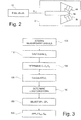
Figure 2 is a more detailed block diagram of a part of the system ofFigure 1 ; and -
Figure 3 is a flowchart regarding a method for controlling a combined-cycle system in accordance with one embodiment of the present invention. - With reference to
Figure 1 , a combined-cycle system for the production of electric power is designated by the number 1. The system 1 comprises a gas-turbine assembly 2, asteam turbine 3, and anelectric generator 4 in single-shaft configuration, i.e., all coupled on one and thesame shaft 5. - A
control device 7 controls the gas-turbine assembly 2, thesteam turbine 3, and theelectric generator 4 on the basis of measurement signals supplied by measuring devices 6 in such a way that the operating conditions of the system 1 are optimised for supplying an electric power PE required by the loads. - The gas-
turbine assembly 2 comprises acompressor 8, acombustion chamber 9, and agas turbine 10. Thecompressor 8 and thegas turbine 10 are mounted on theshaft 5. - The
compressor 10 is provided with an anti-icing device 11 that comprises a recirculation line 12 and a regulating valve 13. The recirculation line 12 connects the outlet and the inlet of thecompressor 8, and the regulating valve 13 enables an anti-icing air flowrate QAI (at approximately 400°C) to be taken from the outlet of thecompressor 8 and to be fed back at inlet to prevent the formation of ice. - An input stage of the
compressor 8 is provided with astage 8a of inlet guide vanes (IGVs), which are controlled by thecontrol device 7 through anIGV actuator 15 for regulating an air flowrate QA taken in by thecompressor 8. The air flowrate QA taken in by thecompressor 8 in turn enables regulation of the exhaust gas temperature TE. - The
combustion chamber 9 is provided withpilot burners 9a andpremixing burners 9b (seeFigure 2 ). A pilot fuel flowrate QFP fed to thepilot burners 9a is regulated by thecontrol device 7, which acts on afuel valve 16. - The system 1 further comprises a
recovery boiler 17, which uses hot exhaust gas from thegas turbine 10 to generate steam for thesteam turbine 3, and acondenser 18, which receives the steam processed by thesteam turbine 3. - The measuring devices 6 supply measurement signals indicative of operating quantities of the system 1. In particular, the measurement signals comprise:
- a signal Sβ indicative of a current compression ratio βC of the
compressor 8; - a signal ST indicative of the ambient temperature;
- a signal STE indicative of the exhaust gas temperature TE;
- a signal SN indicative of the angular speed of the
shaft 5; and - a signal SR indicative of the position of the regulating valve 13.
- The
control device 7 shares the load requested to the system between thegas turbine 10 and thesteam turbine 3, detects the current operating conditions at least of thegas turbine 10 and selects optimal reference values (setpoints) of operating quantities of the system 1 as a function of the detected operating conditions. Moreover, thecontrol device 7 applies regulating signals to the actuators of the system 1, in particular to theIGV actuator 15 and to thefuel valve 16 in such a way that the operating quantities tend to reach the respective setpoints. Thecontrol device 8 also performs a function of supervision of the accessory apparatuses, such as, for example, the anti-icing device 11. In particular, thecontrol device 7 acts on the regulating valve 13 so as to activate the anti-icing device 11 and regulate the anti-icing air flowrate QAI when the ambient temperature drops below a threshold. - In order to determine the operating conditions of the
gas turbine 10, thecontrol device 7 uses the current compression ratio βC of thecompressor 8, which is obtained from the signal Sβ supplied by the measuring devices 6. - The current compression ratio βC is normalized with respect to reference operating conditions and corrected to take into account the effect of factors such as the ambient conditions, the rotation speed of the
shaft 5, and the action of the anti-icing device 11. - The reference conditions may be ISO conditions (temperature T = 15°C; pressure P = 1.013 bar).
- The normalized compression ratio βN is given by

- The corrective temperature coefficient CT takes into account the effect of the ambient temperature, which is detected by the measuring devices 6 (signal ST).
- The corrective speed coefficient C2 depends upon the rotation speed of the
gas turbine 10, which can also be detected by the measuring devices 6 (signal SN). - The corrective flowrate coefficient C3 depends upon an estimate of the anti-icing air flowrate QAI that is taken at output from the
compressor 8 and fed back at input to thecompressor 8 itself. In practice, the third corrective coefficient C3 takes into account that not the entire air flowrate QA taken in by thecompressor 8 is introduced into thecombustion chamber 9 and, moreover, the recirculation of air from the outlet to the inlet of thecompressor 8 modifies the conditions of temperature. In one embodiment, estimation of the anti-icing air flowrate QAI is determined on the basis of the position of the regulating valve 13, which is set by thecontrol device 7. In a different embodiment, the anti-icing air flowrate QAI is measured, for instance with a flowmeter. - It has been found that the normalized compression ratio βN defined above represents the power supplied by the
gas turbine 10, normalized with respect to the same conditions (for example ISO or standard conditions). Hence, in practice, it is possible to determine the load conditions of thegas turbine 10 starting from the calculation of the normalized compression ratio βN. - The
control device 7 operates as described hereinafter, with reference toFigure 3 , to optimize operation of thegas turbine 10 as a function of the load conditions. - The
control device 7 first of all acquires the measurement signals supplied by the measuring devices 6, amongst which in particular (block 100): - the signal Sβ indicative of the current compression ratio βC of the
compressor 8; - the signal ST indicative of the ambient temperature;
- the signal STE indicative of the exhaust gas temperature TE;
- the signal SN indicative of the angular speed of the
shaft 5; and - the signal SR indicative of the position of the regulating valve 13.
- Once the measurement signals have been acquired, the control device calculates the current compression ratio βC from the signal Sβ (block 110) and determines the values of the corrective temperature coefficient CT, of the corrective speed coefficient CN, and of the corrective flowrate coefficient CQ (block 120) using functions determined experimentally and stored, for example, in the form of tables.
- Once the current compression ratio βC and the current values of the corrective temperature coefficient CT, of the corrective speed coefficient CN, and of the corrective flowrate coefficient CQ are available, the
control device 7 calculates the normalized compression ratio βN applying Eq. (1) (block 130) . - Next (block 140), the
control device 7 determines the load conditions of thegas turbine 10 on the basis of the value of the normalized compression ratio βN. For this purpose, a function is used, stored for instance in the form of a table in thecontrol device 7. The function may be defined experimentally, starting from historic series, or else using a model of the system 1, which can be described with sufficient precision to yield reliable results. - In an alternative embodiment, instead of determining the load conditions of the
gas turbine 10 directly from the normalized compression ratio βN, thecontrol device 7 calculates an estimate of the power supplied by thegas turbine 10 on the basis of the normalized compression ratio βN. The load conditions of thegas turbine 10 are then determined as a function of the estimate of the power delivered. - After determining the current load conditions of the
gas turbine 10, thecontrol device 7 selects respective setpoints for the critical quantities that significantly affect the efficiency of the gas turbine 10 (block 150). In particular, thecontrol device 7 defines a first setpoint SPTE, indicative of a target temperature of the exhaust gas, and a second setpoint SPP, indicative of a target pilot fuel flowrate to be fed to the pilot burners of thecombustion chamber 9. - Finally (block 160), the
control device 7 applies a first regulating signal SIGV to theIGV actuator 15 and a second regulating signal SFV to thefuel valve 16 in such a way that the temperature exhaust gas TE and the pilot fuel flowrate QFP supplied to thepilot burners 9a tend to reach the first setpoint SPTE and the second setpoint SPP, respectively. - Thanks to the method described, the power supplied by the gas turbine of a single-shaft combined-cycle system can be easily estimated with good precision and in a reliable way, also considering the fact that the measurement of the current compression ratio βC is normally available in the systems. The parameters of the gas turbine can thus be correctly set as a function of the load and of the ambient conditions, and it is possible to maintain optimal conditions of combustion with high efficiency and low emissions of pollutant substances, in particular NOx.
- Finally, it is evident that modifications and variations may be made to the method and to the system described herein, without departing from the scope of the present invention, as defined in the annexed claims.
Claims (16)
- A method of controlling a combined-cycle system comprising a compressor (8), a gas turbine (10), a steam turbine (3), and an electric generator (4), all coupled to a same shaft (5);
the method comprising:detecting a current compression ratio (βC) of the compressor (8);the method being characterized by:calculating a normalized compression ratio (βN) on the basis of the current compression ratio (βC);determining a load condition of the gas turbine (10) on the basis of the normalized compression ratio (βN); selecting a setpoint (SPTE, SPP) for at least one operating quantity (TE, QFP) of the gas turbine (10) on the basis of the determined condition of load of the gas turbine (10); andapplying regulating signals (SIGV, SFV) to actuators (15, 16) of the gas turbine (10), so that the operating quantity (TE, QFP) of the gas turbine (10) tends to reach the setpoint. - The method according to Claim 1, wherein calculating the normalized compression ratio (βN) comprises determining a ratio between the current compression ratio (βC) and a reference-condition compression ratio (βR).
- The method according to Claim 1 or Claim 2, wherein calculating the normalized compression ratio (βN) comprises applying a corrective temperature coefficient (CT) as a function of an ambient temperature.
- The method according to any one of the preceding claims, wherein calculating the normalized compression ratio (βN) comprises applying a corrective speed coefficient (CN), as a function of a velocity of rotation of the gas turbine (10).
- The method according to any one of the preceding claims, wherein calculating the normalized compression ratio (βN) comprises applying a corrective flowrate coefficient (CQ) as a function of an estimate of an anti-icing flowrate (QAI) taken at outlet from the compressor (8) and fed back at inlet to the compressor (8) .
- The method according to Claim 1, wherein the normalized compression ratio (βN) is given by

where βN is the normalized compression ratio, βC is the current compression ratio, βR is the reference-condition compression ratio; CT is a corrective temperature coefficient, depending upon an ambient temperature, CN is a corrective speed coefficient, depending upon a rotation speed of the gas turbine (10), and CQ is a corrective flowrate coefficient, depending upon an estimate of an anti-icing flowrate taken at outlet from the compressor (8) and fed back at inlet to the compressor (8). - The method according to any one of the preceding claims, wherein determining the load condition of the gas turbine (10) comprises determining an estimate of a power supplied by the gas turbine (10) as a function of the normalized compression ratio (βN).
- The method according to any one of the preceding claims, wherein the at least one operating quantity comprises an exhaust gas temperature (TE) of the gas turbine (10), and the actuators comprise IGV actuators (15) .
- The method according to any one of the preceding claims, wherein the at least one operating quantity comprises a pilot fuel flowrate (QFP) to be supplied to pilot burners (9a) of the gas turbine (10), and the actuators comprise a fuel valve (16).
- A combined-cycle system comprising:a compressor (8), a gas turbine (10), a steam turbine,and an electric generator, all coupled to the same shaft; andmeasuring devices (6), for supplying measurement signals (Sβ, ST, STE, SN, SR) indicative of a current compression ratio (βC) of the compressor (8) ;characterized by a control device (7), configured to:calculate the current compression ratio (βC) from the measurement signals (Sβ);calculate a normalized compression ratio (βN) on the basis of the current compression ratio (βC);determine a load condition of the gas turbine (10) on the basis of the normalized compression ratio (βN);select a setpoint (SPTE, SPP) for at least one operating quantity (TE, QFP) of the gas turbine (10) on the basis of the load condition of the gas turbine (10) determined; andapply regulating signals (SIGV, SFV) to actuators (15, 16) of the gas turbine (10), so that the operating quantity (TE, QFP) of the gas turbine (10) tends to reach the setpoint.
- The system according to Claim 10, wherein the control device (7) is further configured to calculate the normalized compression ratio (βN) on the basis of a ratio between the current compression ratio (βC) and a reference-condition compression ratio (βR).
- The system according to Claim 10 or Claim 11, wherein the control device (7) is further configured to calculate the normalized compression ratio (βN) on the basis of a corrective temperature coefficient (CT) depending upon an ambient temperature.
- The system according to any one of Claims 10 to 12, wherein the control device (7) is further configured to calculate the normalized compression ratio (βN) on the basis of a corrective speed coefficient (CN), depending upon a speed of the gas turbine (10).
- The system according to any one of Claims 10 to 13, wherein the control device (7) is further configured to calculate the normalized compression ratio (βN) on the basis of a corrective flowrate coefficient (CQ), depending upon an estimate of an anti-icing flowrate taken at outlet from the compressor (8) and fed back at inlet to the compressor (8).
- The system according to Claim 10, wherein the control device (7) is further configured to calculate the normalized compression ratio (βN) as

where (βN is the normalized compression ratio, βC is the current compression ratio, βR is the reference-condition compression ratio; CT is a corrective temperature coefficient, depending upon an ambient temperature, CN is a corrective speed coefficient, depending upon a speed of the gas turbine (10), and CQ is a corrective flowrate coefficient, depending upon an estimate of an anti-icing flowrate, taken at outlet from the compressor (8) and fed back at inlet to the compressor (8). - The system according to any one of Claims 10 to 15, wherein determining the load condition of the gas turbine (10) comprises determining an estimate of a power supplied by the gas turbine (10) as a function of the normalized compression ratio (βN).
Applications Claiming Priority (1)
| Application Number | Priority Date | Filing Date | Title |
|---|---|---|---|
| ITTO2010A001077A IT1403788B1 (en) | 2010-12-29 | 2010-12-29 | METHOD FOR CONTROLLING A COMBINED CYCLE PLANT IN "SINGLE-SHAFT" CONFIGURATION AND COMBINED CYCLE SYSTEM IN "SINGLE-SHAFT" CONFIGURATION |
Publications (1)
| Publication Number | Publication Date |
|---|---|
| EP2472073A1 true EP2472073A1 (en) | 2012-07-04 |
Family
ID=43737464
Family Applications (1)
| Application Number | Title | Priority Date | Filing Date |
|---|---|---|---|
| EP11195835A Withdrawn EP2472073A1 (en) | 2010-12-29 | 2011-12-27 | Method of controlling a combined-cycle system in single-shaft configuration and combined-cycle system in single-shaft configuration |
Country Status (3)
| Country | Link |
|---|---|
| US (1) | US20120167581A1 (en) |
| EP (1) | EP2472073A1 (en) |
| IT (1) | IT1403788B1 (en) |
Families Citing this family (7)
| Publication number | Priority date | Publication date | Assignee | Title |
|---|---|---|---|---|
| US10107197B2 (en) * | 2012-11-30 | 2018-10-23 | United Technologies Corporation | Lubrication system for gas turbine engines |
| JP6164994B2 (en) * | 2013-09-06 | 2017-07-19 | 三菱日立パワーシステムズ株式会社 | Gas turbine plant, its control device, and operation method of gas turbine |
| JP6217451B2 (en) | 2014-02-26 | 2017-10-25 | 三菱日立パワーシステムズ株式会社 | Fuel control device, combustor, gas turbine, control method and program |
| JP6364363B2 (en) * | 2015-02-23 | 2018-07-25 | 三菱日立パワーシステムズ株式会社 | Two-shaft gas turbine and control device and control method thereof |
| EP3225812B1 (en) * | 2016-03-29 | 2019-02-27 | Mitsubishi Hitachi Power Systems, Ltd. | A two-shaft gas turbine, and the control method of opening degree of inlet guide vane of the gas turbine |
| KR101971337B1 (en) * | 2017-04-24 | 2019-04-22 | 두산중공업 주식회사 | Gas Turbine System and Controlling Method thereof |
| JP7478597B2 (en) * | 2020-06-08 | 2024-05-07 | 三菱重工業株式会社 | Gas turbine control device and method, and gas turbine |
Citations (4)
| Publication number | Priority date | Publication date | Assignee | Title |
|---|---|---|---|---|
| US20060201132A1 (en) | 2002-05-20 | 2006-09-14 | Kabushiki Kaisha Toshiba | Gas turbine control system |
| US20070271024A1 (en) * | 2006-05-22 | 2007-11-22 | Mitsubishi Heavy Industries, Ltd. | Gas turbine output learning circuit and combustion control device for gas turbine having the same |
| WO2009109446A1 (en) * | 2008-03-05 | 2009-09-11 | Alstom Technology Ltd | Method for regulating a gas turbine in a power plant and power plant to carry out the method |
| EP2128406A1 (en) * | 2008-05-26 | 2009-12-02 | Siemens Aktiengesellschaft | Method for operating a gas turbine |
Family Cites Families (4)
| Publication number | Priority date | Publication date | Assignee | Title |
|---|---|---|---|---|
| US6912856B2 (en) * | 2003-06-23 | 2005-07-05 | General Electric Company | Method and system for controlling gas turbine by adjusting target exhaust temperature |
| ITTO20030828A1 (en) * | 2003-10-21 | 2005-04-22 | Ansaldo Energia Spa | CONTROL SYSTEM FOR GAS TURBINE. |
| US7096667B2 (en) * | 2004-01-09 | 2006-08-29 | Siemens Power Generation, Inc. | Control of gas turbine for catalyst activation |
| US8311684B2 (en) * | 2008-12-17 | 2012-11-13 | Pratt & Whitney Canada Corp. | Output flow control in load compressor |
-
2010
- 2010-12-29 IT ITTO2010A001077A patent/IT1403788B1/en active
-
2011
- 2011-12-27 EP EP11195835A patent/EP2472073A1/en not_active Withdrawn
- 2011-12-28 US US13/338,899 patent/US20120167581A1/en not_active Abandoned
Patent Citations (4)
| Publication number | Priority date | Publication date | Assignee | Title |
|---|---|---|---|---|
| US20060201132A1 (en) | 2002-05-20 | 2006-09-14 | Kabushiki Kaisha Toshiba | Gas turbine control system |
| US20070271024A1 (en) * | 2006-05-22 | 2007-11-22 | Mitsubishi Heavy Industries, Ltd. | Gas turbine output learning circuit and combustion control device for gas turbine having the same |
| WO2009109446A1 (en) * | 2008-03-05 | 2009-09-11 | Alstom Technology Ltd | Method for regulating a gas turbine in a power plant and power plant to carry out the method |
| EP2128406A1 (en) * | 2008-05-26 | 2009-12-02 | Siemens Aktiengesellschaft | Method for operating a gas turbine |
Also Published As
| Publication number | Publication date |
|---|---|
| IT1403788B1 (en) | 2013-10-31 |
| ITTO20101077A1 (en) | 2012-06-30 |
| US20120167581A1 (en) | 2012-07-05 |
Similar Documents
| Publication | Publication Date | Title |
|---|---|---|
| EP2472073A1 (en) | Method of controlling a combined-cycle system in single-shaft configuration and combined-cycle system in single-shaft configuration | |
| EP2604826B1 (en) | System and Method for Warming up a Steam Turbine | |
| EP2660511B1 (en) | Condensate flow rate control device for power-plant, and control method | |
| EP2752568B1 (en) | Valve control device, gas turbine, and valve control method | |
| US11746712B2 (en) | Controller and method | |
| US20170211409A1 (en) | Control device, system, and control method | |
| JP5501870B2 (en) | gas turbine | |
| CA3089687C (en) | Controller and method | |
| JP6267087B2 (en) | Power control apparatus, gas turbine, and power control method | |
| JP6193827B2 (en) | Fuel supply device, combustor, gas turbine, and fuel supply method | |
| US10883389B2 (en) | Combined cycle plant, method for reducing minimum output thereof, and control device therefor | |
| US11125166B2 (en) | Control system, gas turbine, power generation plant, and method of controlling fuel temperature | |
| CN114278441B (en) | Gas turbine and fuel flow rate adjustment method thereof | |
| JP6413145B2 (en) | Gas turbine equipment, control device therefor, and control method for gas turbine equipment | |
| EP3358166B1 (en) | Humid air turbine | |
| US12523377B2 (en) | Gas turbine control device, gas turbine control method, and storage medium | |
| JPH07301128A (en) | Gas turbine exhaust gas temperature control device | |
| EP1835592A1 (en) | Method and system for controlling a combination-cycle electric power plant, in particular a single-shaft plant | |
| EP2412936A1 (en) | Method for managing a primary reserve margin in an electric power generation plant and electric power generation plant | |
| EP2295735A1 (en) | Control method and device for controlling a combined-cycle power plant, and combined-cycle power plant |
Legal Events
| Date | Code | Title | Description |
|---|---|---|---|
| AK | Designated contracting states |
Kind code of ref document: A1 Designated state(s): AL AT BE BG CH CY CZ DE DK EE ES FI FR GB GR HR HU IE IS IT LI LT LU LV MC MK MT NL NO PL PT RO RS SE SI SK SM TR |
|
| AX | Request for extension of the european patent |
Extension state: BA ME |
|
| PUAI | Public reference made under article 153(3) epc to a published international application that has entered the european phase |
Free format text: ORIGINAL CODE: 0009012 |
|
| STAA | Information on the status of an ep patent application or granted ep patent |
Free format text: STATUS: THE APPLICATION IS DEEMED TO BE WITHDRAWN |
|
| 18D | Application deemed to be withdrawn |
Effective date: 20130105 |