EP2472062B1 - Gas turbine engine and airfoil - Google Patents
Gas turbine engine and airfoil Download PDFInfo
- Publication number
- EP2472062B1 EP2472062B1 EP11250947.6A EP11250947A EP2472062B1 EP 2472062 B1 EP2472062 B1 EP 2472062B1 EP 11250947 A EP11250947 A EP 11250947A EP 2472062 B1 EP2472062 B1 EP 2472062B1
- Authority
- EP
- European Patent Office
- Prior art keywords
- cooling air
- airfoil
- wall
- cooling
- ribs
- Prior art date
- Legal status (The legal status is an assumption and is not a legal conclusion. Google has not performed a legal analysis and makes no representation as to the accuracy of the status listed.)
- Revoked
Links
Images

Classifications
-
- F—MECHANICAL ENGINEERING; LIGHTING; HEATING; WEAPONS; BLASTING
- F01—MACHINES OR ENGINES IN GENERAL; ENGINE PLANTS IN GENERAL; STEAM ENGINES
- F01D—NON-POSITIVE DISPLACEMENT MACHINES OR ENGINES, e.g. STEAM TURBINES
- F01D5/00—Blades; Blade-carrying members; Heating, heat-insulating, cooling or antivibration means on the blades or the members
- F01D5/12—Blades
- F01D5/14—Form or construction
- F01D5/18—Hollow blades, i.e. blades with cooling or heating channels or cavities; Heating, heat-insulating or cooling means on blades
- F01D5/187—Convection cooling
-
- F—MECHANICAL ENGINEERING; LIGHTING; HEATING; WEAPONS; BLASTING
- F01—MACHINES OR ENGINES IN GENERAL; ENGINE PLANTS IN GENERAL; STEAM ENGINES
- F01D—NON-POSITIVE DISPLACEMENT MACHINES OR ENGINES, e.g. STEAM TURBINES
- F01D5/00—Blades; Blade-carrying members; Heating, heat-insulating, cooling or antivibration means on the blades or the members
- F01D5/12—Blades
- F01D5/14—Form or construction
- F01D5/18—Hollow blades, i.e. blades with cooling or heating channels or cavities; Heating, heat-insulating or cooling means on blades
- F01D5/186—Film cooling
-
- Y—GENERAL TAGGING OF NEW TECHNOLOGICAL DEVELOPMENTS; GENERAL TAGGING OF CROSS-SECTIONAL TECHNOLOGIES SPANNING OVER SEVERAL SECTIONS OF THE IPC; TECHNICAL SUBJECTS COVERED BY FORMER USPC CROSS-REFERENCE ART COLLECTIONS [XRACs] AND DIGESTS
- Y02—TECHNOLOGIES OR APPLICATIONS FOR MITIGATION OR ADAPTATION AGAINST CLIMATE CHANGE
- Y02T—CLIMATE CHANGE MITIGATION TECHNOLOGIES RELATED TO TRANSPORTATION
- Y02T50/00—Aeronautics or air transport
- Y02T50/60—Efficient propulsion technologies, e.g. for aircraft
Definitions
- the present invention relates to gas turbine engines, and more particularly, to airfoils for gas turbine engines.
- EP1617043 discloses a cooling circuit disposed within a wall particularly within a gas turbine engine.
- the cooling circuit includes a forward end, an aft end and pedestals which extend between first and second portions of the wall.
- the characteristics and array of the pedestals within the cooling circuit are chosen to provide a heat transfer cooling profile within the cooling circuit that substantially offsets the profile of the thermal load applied to the wall portion containing the cooling circuit.
- At least one inlet aperture provides a cooling airflow path into the forward portion of the cooling circuit from a cavity.
- a plurality of exit apertures provide a cooling airflow path out of the aft portion of the cooling circuit and into the core gas path outside the wall. In one embodiment the flow area of the cooling circuit decreases from the inlet aperture to the exit apertures.
- WO0053896 discloses a turbine blade which extends along a principal axis from a bottom area via a blade area that can be subjected to hot gas to a top area.
- the turbine blade is essentially formed of carbon that is reinforced by carbon fibres. At least the blade area is provided with a blade outer wall with carbon that is reinforced by carbon fibres. Said wall is surrounded by a protective layer.
- the invention also relates to a method for producing a turbine blade.
- an airfoil for a gas turbine engine as set out in claim 1.
- One embodiment of the present invention is a unique gas turbine engine. Another embodiment is a unique turbine engine airfoil. Other embodiments include apparatuses, systems, devices, hardware, methods, and combinations for gas turbine engines and airfoils. Further embodiments, forms, features, aspects, benefits, and advantages of the present application will become apparent from the description and figures provided herewith.
- gas turbine engine 10 is an aircraft propulsion power plant.
- gas turbine engine 10 may be a land-based or marine engine.
- gas turbine engine 10 is a multi-spool turbofan engine.
- gas turbine engine 10 may take other forms, and may be, for example, a turboshaft engine, a turbojet engine, a turboprop engine, or a combined cycle engine.
- gas turbine engine 10 includes a fan system 12, a bypass duct 14, a compressor system 16, a diffuser 18, a combustion system 20, a turbine system 22, a discharge duct 26 and a nozzle 28.
- Bypass duct 14 and compressor system 16 are in fluid communication with fan system 12.
- Diffuser 18 is in fluid communication with compressor system 16.
- Combustion system 20 is fluidly disposed between compressor system 16 and turbine system 22.
- combustion system 20 includes a combustion liner (not shown) that contains a continuous combustion process.
- combustion system 20 may take other forms, and may be, for example, a wave rotor combustion system, a rotary valve combustion system, or a slinger combustion system, and may employ deflagration and/or detonation combustion processes.
- Fan system 12 includes a fan rotor system 30.
- fan rotor system 30 includes one or more rotors (not shown) that are powered by turbine system 22.
- Bypass duct 14 is operative to transmit a bypass flow generated by fan system 12 to nozzle 28.
- Compressor system 16 includes a compressor rotor system 32.
- compressor rotor system 32 includes one or more rotors (not shown) that are powered by turbine system 22.
- Each compressor rotor includes a plurality of compressor blades (not shown).
- Turbine system 22 includes a turbine rotor system 34.
- turbine rotor system 34 includes one or more rotors (not shown) operative to drive fan rotor system 30 and compressor rotor system 32.
- Turbine rotor system 34 is drivingly coupled to compressor rotor system 32 and fan rotor system 30 via a shafting system 36.
- shafting system 36 includes a plurality of shafts that may rotate at the same or different speeds and directions. In some embodiments, only a single shaft may be employed.
- Turbine system 22 is operative to discharge an engine 10 core flow to nozzle 28.
- fan rotor system 30, compressor rotor system 32, turbine rotor system 34 and shafting system 36 rotate about an engine centerline 48. In other embodiments, all or parts of fan rotor system 30, compressor rotor system 32, turbine rotor system 34 and shafting system 36 may rotate about one or more other axes of rotation in addition to or in place of engine centerline 48.
- Discharge duct 26 extends between a discharge portion 40 of turbine system 22 and engine nozzle 28. Discharge duct 26 is operative to direct bypass flow and core flow from a bypass duct discharge portion 38 and turbine discharge portion 40, respectively, into nozzle system 28. In some embodiments, discharge duct 26 may be considered a part of nozzle 28. Nozzle 28 in fluid communication with fan system 12 and turbine system 22. Nozzle 28 is operative to receive the bypass flow from fan system 12 via bypass duct 14, and to receive the core flow from turbine system 22, and to discharge both as an engine exhaust flow, e.g., a thrust-producing flow.
- air is drawn into the inlet of fan 12 and pressurized by fan 12.
- Some of the air pressurized by fan 12 is directed into compressor system 16 as core flow, and some of the pressurized air is directed into bypass duct 14 as bypass flow, and is discharged into nozzle 28 via discharge duct 26.
- Compressor system 16 further pressurizes the portion of the air received therein from fan 12, which is then discharged into diffuser 18.
- Diffuser 18 reduces the velocity of the pressurized air, and directs the diffused core airflow into combustion system 20.
- Fuel is mixed with the pressurized air in combustion system 20, which is then combusted.
- the hot gases exiting combustor 20 are directed into turbine system 22, which extracts energy in the form of mechanical shaft power sufficient to drive fan system 12 and compressor system 16 via shafting system 36.
- the core flow exiting turbine system 22 is directed along an engine tail cone 42 and into discharge duct 26, along with the bypass flow from bypass duct 14.
- Discharge duct 26 is configured to receive the bypass flow and the core flow, and to discharge both as an engine exhaust flow, e.g., for providing thrust, such as for aircraft propulsion.
- Compressor rotor system 32 includes a plurality of blades and vanes (not shown) employed to add energy to the gases prior to combustion.
- Turbine rotor system 34 includes a plurality of blades and vanes (not shown) employed to extract energy from the high temperature high pressure gases in the flowpath. It is desirable to maintain the temperature of blades and vanes within certain temperature limits, e.g., based on the materials and coatings employed in the blades and vanes.
- blades and vanes are cooled by injecting cooling air into the blade or vane. The blades rotate with the corresponding rotor during the operation of engine 10, which may increase the degree of difficulty in cooling the blade because the cooling air tends to migrate radially outward due to centrifugal force.
- Embodiments of the present invention includes an airfoil configured to mitigate and/or prevent the migration of cooling air due to centrifugal loading.
- airfoil 50 is a turbine blade. In other embodiments, airfoil 50 may be a compressor blade. In still other embodiments, airfoil 50 may be a turbine or compressor vane. In one form, airfoil 50 is a dual wall airfoil. In other embodiments, airfoil 50 may be a single wall airfoil or an airfoil having more than two walls. Airfoil 50 includes a spar 52 and an outer skin 54. In one form, airfoil 50 is formed of a conventional aerospace material, such as CMSX-4, available from Cannon Muskegon Corporation of Muskegon, MI, USA. In other embodiments, other materials, conventional or otherwise, may be employed.
- CMSX-4 conventional aerospace material
- spar 52 is hollow, having an internal volume that forms a cooling air supply passage 56.
- one or more other cooling air supply passages may be employed in addition to or in place of cooling air supply passage 56.
- cooling air supply passage 56 may be positioned adjacent to an inner wall other than spar 52.
- Spar 52 includes a plurality of cooling air inlet openings 58 extending through the wall of spar 52. Cooling air supply passage 56 is in fluid communication with cooling air inlet openings 58. Cooling air supply passage 56 is operative to supply cooling air to cooling air inlet openings 58.
- Outer skin 54 forms an outer wall for airfoil 50 on both the pressure side and the suction side of airfoil 50.
- outer skin 54 extends around both the pressure side and the suction side.
- outer skin 54 may be in the form of individual sheets, e.g., one outer wall for each of the pressure side and the suction side of airfoil 50, e.g., illustrated in FIG. 3 as an outer wall 54A for the pressure side, and an outer wall 54B for the suction side.
- spar 52 extends around both the pressure side and the suction side.
- spar 52 may be in the form of individual structures, e.g., one inner wall for each of the pressure side and the suction side of airfoil 50, e.g., illustrated in FIG. 3 as an inner wall 52A for the pressure side, and an inner wall 52B for the suction side.
- Outer skin 54 includes a plurality of cooling air exit openings 60.
- Spar 52 forms an inner wall for airfoil 50 on both the pressure side and the suction side of airfoil 50.
- Outer skin 54 and spar 52 are spaced apart from each other by a plurality of ribs 62.
- ribs 62 extend between the outer wall formed by outer skin 54 and the inner wall formed by spar 52. In other embodiments, ribs 62 may extend between other walls in addition to or in place of outer skin 54 and spar 52.
- ribs 62 form a plurality of flow migration dams configured to reduce or prevent cooling air flow migration in a radially outward direction, e.g., due to centrifugal force during the rotation of airfoil 50 in the form of a turbine engine blade.
- ribs 62 are oriented horizontally in airfoil 50. In other embodiments, ribs 62 may be oriented in other directions in addition to or in place of horizontal.
- airfoil 50 may have an attachment feature 64 configured to mechanically couple airfoil 50 to engine 10. In one form, attachment feature 64 is operative to deliver cooling air to cooling air supply passage 56.
- cooling passage 66 Each adjacent pair of ribs 62 form therebetween a cooling passage 66.
- ribs 52 and cooling passages 66 are formed on both the pressure side and the suction side of airfoil 50. In other embodiments, ribs 52 and cooling passages 66 may be formed only on either the pressure side or the suction side of airfoil 50. In some embodiments, cooling passages 66 may also be formed between ribs 62 and end structures of airfoil 50, e.g., at the root and tip of airfoil 50 (not shown). In one form, cooling passages 66 are bound by adjacent pairs of ribs 62 and by outer skin 54 and spar 52.
- cooling passages 66 may be bound by other walls in addition to ribs 62. Cooling passages 66 are in fluid communication with cooling air inlet openings 58 and with cooling air exit openings 60. In one form, each cooling passage 66 is in fluid communication with cooling air inlet openings 58 at one end, and with cooling air exit openings 60 at the opposite end. In other embodiments, cooling passages 66, cooling air inlet openings 58 and cooling air exit openings 60 may be arranged otherwise. In one form, each cooling passage 66 adjacent to and in fluid communication with a single cooling air inlet opening 58 and with a single cooling air exit opening 60 and operative to receive cooling air from the single cooling air inlet opening 58 and the single cooling air exit opening 60. In other embodiments, each cooling passage 66 may be adjacent to and in fluid communication with a plurality of cooling air inlet openings 58 and/or a plurality of cooling air exit openings 60.
- cooling air is delivered from cooling air supply passage 56 to cooling passages 66 via cooling air inlet openings 58.
- the cooling air exits cooling passages 66 via cooling air exit openings 60.
- cooling passages 66 are operative to flow cooling air to remove heat from outer skin 54 and spar 52.
- cooling passages 66 extend continuously between the leading edge portion 68 of airfoil 50 and the trailing edge portion 70 of airfoil 50.
- ribs 62 are configured to form vortexes 72 in cooling passages 66. In a particular form, ribs 62 are configured to form a series of vortexes 72 in cooling passages 66. In one form, ribs 62 are configured to form vortexes on each side of cooling passages 66. e.g., the top and bottom of each cooling passage 66. In other embodiments, ribs 62 may not be configured to form vortexes in cooling passages 66. In one form, ribs 62 include a plurality of trip strips (turbulators) 74 extending from ribs 62 into cooling passages 66. Trip strips 74 are configured to generate vortexes in the cooling air passing through cooling passages 66. In other embodiments, trip strips 74 may not extend from ribs 62, e.g., may be otherwise formed or extend within cooling passages 66.
- ribs 62 may be configured to form vortexes by virtue of having a particular shape, e.g., yielding a tortuous flowpath shape of cooling passages 66, non-limiting examples of which are illustrated in FIGS. 5A-5E .
- Other shapes may be employed in other embodiments.
- Embodiments of the present invention include an airfoil for a gas turbine engine, comprising: an outer wall having a plurality cooling air exit openings; an inner wall spaced apart from the outer wall, wherein the inner wall has a plurality of cooling air inlet openings; a plurality of flow migration dams, wherein the flow migration dams extend between the inner wall and the outer wall, the plurality of flow migration dams forming therebetween a plurality of cooling passages, wherein the cooling passages are in fluid communication with the cooling air inlet openings and with the cooling air exit openings; and a cooling air supply passage in fluid communication with the cooling air inlet openings, wherein the cooling air supply passage is operative to supply cooling air to the cooling air inlet openings.
- the airfoil further comprises a one or more trip strips in one or more cooling passages configured to generate one or more vortexes.
- the one or more trip strips extend from the flow migration dams.
- the one or more trip strips include a series of trip strips in each cooling passage, wherein the series of trip strips is configured to generate a series of vortexes in each cooling passage.
- the one or more trip strips extend from the flow migration dams.
- the migration dams are oriented horizontally.
- the cooling passages each have a first end and a second end opposite the first end, and wherein the cooling passages are in fluid communication with the cooling air inlet openings at the first ends, and in fluid communication with the cooling air exit openings at the second ends.
- the flow migration dams are configured to reduce cooling air flow migration in a radially outward direction due to centrifugal force.
- the cooling air supply passage is disposed adjacent to the inner wall.
- the inner wall forms a spar for the airfoil.
- the airfoil is configured as a dual wall airfoil.
- the outer wall and the inner wall are disposed on a pressure side of the airfoil, further comprising: a second outer wall disposed on a suction side of the airfoil, the second outer wall having a second plurality cooling air exit openings; a second inner wall disposed on a suction side of the airfoil and spaced apart from the second outer wall, wherein the second inner wall has a second plurality of cooling air inlet openings; a second plurality of flow migration dams, wherein the flow migration dams extend between the second inner wall and the second outer wall, the second plurality of flow migration dams forming therebetween a second plurality of cooling passages, wherein the second cooling passages are in fluid communication with the second cooling air inlet openings and with the second cooling air exit openings, wherein the cooling air supply passage is disposed between the inner wall and the second inner wall, and is in fluid communication with the second cooling air inlet openings, wherein the cooling air supply passage is operative to supply cooling air to the second cooling air in
- the airfoil has a leading edge portion and a trailing edge portion; and wherein the flow migration dams extend continuously between the leading edge portion and the trailing edge portion.
- Embodiments include a turbine engine, comprising: an airfoil, the airfoil including: a hollow spar structure having a plurality of cooling air inlet openings, wherein an internal volume in the hollow spar structure forms a cooling air supply passage operative to deliver cooling air to the cooling air inlet openings; an outer skin spaced apart from the hollow spar structure by a plurality of ribs, wherein the plurality of ribs form a plurality of cooling passages, each cooling passage being defined between an adjacent pair of ribs, wherein the cooling air inlet openings are in fluid communication with the cooling passages; and wherein the outer skin includes a plurality of cooling air exit openings in fluid communication with the plurality of cooling passages.
- the ribs are configured to form vortexes in the cooling passages.
- the ribs are configured to form a series of vortexes in each cooling passage.
- the ribs are configured to form vortexes on each side of the cooling passages.
- one or more ribs include one or more trip strips extending from the one or more ribs, and wherein the one or more trip strips are configured to generate one or more vortexes.
- the ribs are configured to prevent a migration of flow of cooling air between the hollow spar structure and the outer skin in a radial direction.
- Embodiments of the present invention include an airfoil for a turbine engine, comprising: an outer wall having a plurality cooling air exit openings; an inner wall spaced apart from the outer wall, wherein the inner wall has a plurality of cooling air inlet openings; a cooling air supply passage in fluid communication with the cooling air inlet openings, wherein the cooling air supply passage is operative to supply cooling air to the cooling air inlet openings, and means for cooling the outer wall without allowing flow migration in a radially outward direction, wherein the means for cooling is in fluid communication with both the cooling air inlet openings and the cooling air exit openings.
Landscapes
- Engineering & Computer Science (AREA)
- Mechanical Engineering (AREA)
- General Engineering & Computer Science (AREA)
- Turbine Rotor Nozzle Sealing (AREA)
Description
- The present invention relates to gas turbine engines, and more particularly, to airfoils for gas turbine engines.
- Gas turbine engine airfoils, particularly those that require cooling, remain an area of interest Some existing systems have various shortcomings, drawbacks, and disadvantages relative to certain applications. Accordingly, there remains a need for further contributions in this area of technology.
-
EP1617043 discloses a cooling circuit disposed within a wall particularly within a gas turbine engine. The cooling circuit includes a forward end, an aft end and pedestals which extend between first and second portions of the wall. The characteristics and array of the pedestals within the cooling circuit are chosen to provide a heat transfer cooling profile within the cooling circuit that substantially offsets the profile of the thermal load applied to the wall portion containing the cooling circuit. At least one inlet aperture provides a cooling airflow path into the forward portion of the cooling circuit from a cavity. A plurality of exit apertures provide a cooling airflow path out of the aft portion of the cooling circuit and into the core gas path outside the wall. In one embodiment the flow area of the cooling circuit decreases from the inlet aperture to the exit apertures. -
WO0053896 - According to an aspect of the invention there is provided an airfoil for a gas turbine engine as set out in claim 1.
- One embodiment of the present invention is a unique gas turbine engine. Another embodiment is a unique turbine engine airfoil. Other embodiments include apparatuses, systems, devices, hardware, methods, and combinations for gas turbine engines and airfoils. Further embodiments, forms, features, aspects, benefits, and advantages of the present application will become apparent from the description and figures provided herewith.
- The description herein makes reference to the accompanying drawings wherein like reference numerals refer to like parts throughout the several views, and wherein:
-
FIG. 1 schematically illustrates some aspects of a non-limiting example of a gas turbine engine in accordance with an embodiment of the present invention. -
FIG. 2 illustrates some aspects of a non-limiting example of an airfoil in accordance with an embodiment of the present invention. -
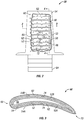
FIG. 3 illustrates some aspects of a non-limiting example of a cross section of the airfoil ofFIG. 2 . -
FIG. 4 illustrates some aspects of a non-limiting example of a cross section of the airfoil ofFIG. 2 . -
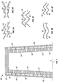
FIGS. 5A-5E illustrate some aspects of a non-exhaustive group of non-limiting examples of different rib designs in accordance with embodiments of the present invention. - For purposes of promoting an understanding of the principles of the invention, reference will now be made to the embodiments illustrated in the drawings, and specific language will be used to describe the same. It will nonetheless be understood that no limitation of the scope of the invention is intended by the illustration and description of certain embodiments of the invention. In addition, any alterations and/or modifications of the illustrated and/or described embodiment(s) are contemplated as being within the scope of the present invention. Further, any other applications of the principles of the invention, as illustrated and/or described herein, as would normally occur to one skilled in the art to which the invention pertains, are contemplated as being within the scope of the present invention.
- Referring to the drawings, and in particular
FIG. 1 , a non-limiting example of some aspects of agas turbine engine 10 in accordance with an embodiment of the present invention is schematically depicted. In one form,gas turbine engine 10 is an aircraft propulsion power plant. In other embodiments,gas turbine engine 10 may be a land-based or marine engine. In one form,gas turbine engine 10 is a multi-spool turbofan engine. In other embodiments,gas turbine engine 10 may take other forms, and may be, for example, a turboshaft engine, a turbojet engine, a turboprop engine, or a combined cycle engine. - As a turbofan engine,
gas turbine engine 10 includes afan system 12, abypass duct 14, acompressor system 16, adiffuser 18, acombustion system 20, aturbine system 22, adischarge duct 26 and anozzle 28.Bypass duct 14 andcompressor system 16 are in fluid communication withfan system 12. Diffuser 18 is in fluid communication withcompressor system 16.Combustion system 20 is fluidly disposed betweencompressor system 16 andturbine system 22. In one form,combustion system 20 includes a combustion liner (not shown) that contains a continuous combustion process. In other embodiments,combustion system 20 may take other forms, and may be, for example, a wave rotor combustion system, a rotary valve combustion system, or a slinger combustion system, and may employ deflagration and/or detonation combustion processes. -
Fan system 12 includes afan rotor system 30. In various embodiments,fan rotor system 30 includes one or more rotors (not shown) that are powered byturbine system 22.Bypass duct 14 is operative to transmit a bypass flow generated byfan system 12 tonozzle 28.Compressor system 16 includes acompressor rotor system 32. In various embodiments,compressor rotor system 32 includes one or more rotors (not shown) that are powered byturbine system 22. Each compressor rotor includes a plurality of compressor blades (not shown).Turbine system 22 includes aturbine rotor system 34. In various embodiments,turbine rotor system 34 includes one or more rotors (not shown) operative to drivefan rotor system 30 andcompressor rotor system 32. Each turbine rotor includes a plurality of turbine blades (not shown)Turbine rotor system 34 is drivingly coupled tocompressor rotor system 32 andfan rotor system 30 via ashafting system 36. In various embodiments,shafting system 36 includes a plurality of shafts that may rotate at the same or different speeds and directions. In some embodiments, only a single shaft may be employed.Turbine system 22 is operative to discharge anengine 10 core flow tonozzle 28. In one form,fan rotor system 30,compressor rotor system 32,turbine rotor system 34 andshafting system 36 rotate about anengine centerline 48. In other embodiments, all or parts offan rotor system 30,compressor rotor system 32,turbine rotor system 34 andshafting system 36 may rotate about one or more other axes of rotation in addition to or in place ofengine centerline 48. -
Discharge duct 26 extends between adischarge portion 40 ofturbine system 22 andengine nozzle 28.Discharge duct 26 is operative to direct bypass flow and core flow from a bypassduct discharge portion 38 andturbine discharge portion 40, respectively, intonozzle system 28. In some embodiments,discharge duct 26 may be considered a part ofnozzle 28.Nozzle 28 in fluid communication withfan system 12 andturbine system 22. Nozzle 28 is operative to receive the bypass flow fromfan system 12 viabypass duct 14, and to receive the core flow fromturbine system 22, and to discharge both as an engine exhaust flow, e.g., a thrust-producing flow. - During the operation of
gas turbine engine 10, air is drawn into the inlet offan 12 and pressurized byfan 12. Some of the air pressurized byfan 12 is directed intocompressor system 16 as core flow, and some of the pressurized air is directed intobypass duct 14 as bypass flow, and is discharged intonozzle 28 viadischarge duct 26.Compressor system 16 further pressurizes the portion of the air received therein fromfan 12, which is then discharged intodiffuser 18.Diffuser 18 reduces the velocity of the pressurized air, and directs the diffused core airflow intocombustion system 20. Fuel is mixed with the pressurized air incombustion system 20, which is then combusted. The hotgases exiting combustor 20 are directed intoturbine system 22, which extracts energy in the form of mechanical shaft power sufficient to drivefan system 12 andcompressor system 16 via shaftingsystem 36. The core flow exitingturbine system 22 is directed along anengine tail cone 42 and intodischarge duct 26, along with the bypass flow frombypass duct 14.Discharge duct 26 is configured to receive the bypass flow and the core flow, and to discharge both as an engine exhaust flow, e.g., for providing thrust, such as for aircraft propulsion. -
Compressor rotor system 32 includes a plurality of blades and vanes (not shown) employed to add energy to the gases prior to combustion.Turbine rotor system 34 includes a plurality of blades and vanes (not shown) employed to extract energy from the high temperature high pressure gases in the flowpath. It is desirable to maintain the temperature of blades and vanes within certain temperature limits, e.g., based on the materials and coatings employed in the blades and vanes. In many cases, blades and vanes are cooled by injecting cooling air into the blade or vane. The blades rotate with the corresponding rotor during the operation ofengine 10, which may increase the degree of difficulty in cooling the blade because the cooling air tends to migrate radially outward due to centrifugal force. Embodiments of the present invention includes an airfoil configured to mitigate and/or prevent the migration of cooling air due to centrifugal loading. - Referring to
FIGS. 2-4 , a non-limiting example of some aspects of anairfoil 50 in accordance with an embodiment of the present invention is depicted. In one form,airfoil 50 is a turbine blade. In other embodiments,airfoil 50 may be a compressor blade. In still other embodiments,airfoil 50 may be a turbine or compressor vane. In one form,airfoil 50 is a dual wall airfoil. In other embodiments,airfoil 50 may be a single wall airfoil or an airfoil having more than two walls.Airfoil 50 includes aspar 52 and anouter skin 54. In one form,airfoil 50 is formed of a conventional aerospace material, such as CMSX-4, available from Cannon Muskegon Corporation of Muskegon, MI, USA. In other embodiments, other materials, conventional or otherwise, may be employed. - In one form, spar 52 is hollow, having an internal volume that forms a cooling
air supply passage 56. In other embodiments, one or more other cooling air supply passages may be employed in addition to or in place of coolingair supply passage 56. In other embodiments, coolingair supply passage 56 may be positioned adjacent to an inner wall other thanspar 52.Spar 52 includes a plurality of coolingair inlet openings 58 extending through the wall ofspar 52. Coolingair supply passage 56 is in fluid communication with coolingair inlet openings 58. Coolingair supply passage 56 is operative to supply cooling air to coolingair inlet openings 58. -
Outer skin 54 forms an outer wall forairfoil 50 on both the pressure side and the suction side ofairfoil 50. In one form,outer skin 54 extends around both the pressure side and the suction side. In other embodiments,outer skin 54 may be in the form of individual sheets, e.g., one outer wall for each of the pressure side and the suction side ofairfoil 50, e.g., illustrated inFIG. 3 as anouter wall 54A for the pressure side, and anouter wall 54B for the suction side. Similarly, in one form, spar 52 extends around both the pressure side and the suction side. In other embodiments, spar 52 may be in the form of individual structures, e.g., one inner wall for each of the pressure side and the suction side ofairfoil 50, e.g., illustrated inFIG. 3 as aninner wall 52A for the pressure side, and aninner wall 52B for the suction side. -
Outer skin 54 includes a plurality of coolingair exit openings 60.Spar 52 forms an inner wall forairfoil 50 on both the pressure side and the suction side ofairfoil 50.Outer skin 54 andspar 52 are spaced apart from each other by a plurality ofribs 62. In one form,ribs 62 extend between the outer wall formed byouter skin 54 and the inner wall formed byspar 52. In other embodiments,ribs 62 may extend between other walls in addition to or in place ofouter skin 54 andspar 52. In one form,ribs 62 form a plurality of flow migration dams configured to reduce or prevent cooling air flow migration in a radially outward direction, e.g., due to centrifugal force during the rotation ofairfoil 50 in the form of a turbine engine blade. In one form,ribs 62 are oriented horizontally inairfoil 50. In other embodiments,ribs 62 may be oriented in other directions in addition to or in place of horizontal. In one form,airfoil 50 may have anattachment feature 64 configured to mechanically coupleairfoil 50 toengine 10. In one form,attachment feature 64 is operative to deliver cooling air to coolingair supply passage 56. - Each adjacent pair of
ribs 62 form therebetween acooling passage 66. In one form,ribs 52 andcooling passages 66 are formed on both the pressure side and the suction side ofairfoil 50. In other embodiments,ribs 52 andcooling passages 66 may be formed only on either the pressure side or the suction side ofairfoil 50. In some embodiments, coolingpassages 66 may also be formed betweenribs 62 and end structures ofairfoil 50, e.g., at the root and tip of airfoil 50 (not shown). In one form, coolingpassages 66 are bound by adjacent pairs ofribs 62 and byouter skin 54 andspar 52. In other embodiments, coolingpassages 66 may be bound by other walls in addition toribs 62. Coolingpassages 66 are in fluid communication with coolingair inlet openings 58 and with coolingair exit openings 60. In one form, each coolingpassage 66 is in fluid communication with coolingair inlet openings 58 at one end, and with coolingair exit openings 60 at the opposite end. In other embodiments, coolingpassages 66, coolingair inlet openings 58 and coolingair exit openings 60 may be arranged otherwise. In one form, each coolingpassage 66 adjacent to and in fluid communication with a single coolingair inlet opening 58 and with a single coolingair exit opening 60 and operative to receive cooling air from the single coolingair inlet opening 58 and the single coolingair exit opening 60. In other embodiments, each coolingpassage 66 may be adjacent to and in fluid communication with a plurality of coolingair inlet openings 58 and/or a plurality of coolingair exit openings 60. - During
engine 10 operation, cooling air is delivered from coolingair supply passage 56 to coolingpassages 66 via coolingair inlet openings 58. The cooling air exitscooling passages 66 via coolingair exit openings 60. In one form, coolingpassages 66 are operative to flow cooling air to remove heat fromouter skin 54 andspar 52. In one form, coolingpassages 66 extend continuously between theleading edge portion 68 ofairfoil 50 and the trailingedge portion 70 ofairfoil 50. - In one form,
ribs 62 are configured to formvortexes 72 incooling passages 66. In a particular form,ribs 62 are configured to form a series ofvortexes 72 incooling passages 66. In one form,ribs 62 are configured to form vortexes on each side ofcooling passages 66. e.g., the top and bottom of eachcooling passage 66. In other embodiments,ribs 62 may not be configured to form vortexes in coolingpassages 66. In one form,ribs 62 include a plurality of trip strips (turbulators) 74 extending fromribs 62 intocooling passages 66. Trip strips 74 are configured to generate vortexes in the cooling air passing throughcooling passages 66. In other embodiments, trip strips 74 may not extend fromribs 62, e.g., may be otherwise formed or extend withincooling passages 66. - In other embodiments,
ribs 62 may be configured to form vortexes by virtue of having a particular shape, e.g., yielding a tortuous flowpath shape ofcooling passages 66, non-limiting examples of which are illustrated inFIGS. 5A-5E . Other shapes may be employed in other embodiments. - Embodiments of the present invention include an airfoil for a gas turbine engine, comprising: an outer wall having a plurality cooling air exit openings; an inner wall spaced apart from the outer wall, wherein the inner wall has a plurality of cooling air inlet openings; a plurality of flow migration dams, wherein the flow migration dams extend between the inner wall and the outer wall, the plurality of flow migration dams forming therebetween a plurality of cooling passages, wherein the cooling passages are in fluid communication with the cooling air inlet openings and with the cooling air exit openings; and a cooling air supply passage in fluid communication with the cooling air inlet openings, wherein the cooling air supply passage is operative to supply cooling air to the cooling air inlet openings.
- In a refinement, the airfoil further comprises a one or more trip strips in one or more cooling passages configured to generate one or more vortexes.
- In another refinement, the one or more trip strips extend from the flow migration dams.
- In yet another refinement, the one or more trip strips include a series of trip strips in each cooling passage, wherein the series of trip strips is configured to generate a series of vortexes in each cooling passage.
- In still another refinement, the one or more trip strips extend from the flow migration dams.
- In yet still another refinement, the migration dams are oriented horizontally.
- In a further refinement, the cooling passages each have a first end and a second end opposite the first end, and wherein the cooling passages are in fluid communication with the cooling air inlet openings at the first ends, and in fluid communication with the cooling air exit openings at the second ends.
- In a yet further refinement, the flow migration dams are configured to reduce cooling air flow migration in a radially outward direction due to centrifugal force.
- In a still further refinement, the cooling air supply passage is disposed adjacent to the inner wall.
- In a yet still further refinement, the inner wall forms a spar for the airfoil.
- In an additional refinement, the airfoil is configured as a dual wall airfoil.
- In another additional refinement, the outer wall and the inner wall are disposed on a pressure side of the airfoil, further comprising: a second outer wall disposed on a suction side of the airfoil, the second outer wall having a second plurality cooling air exit openings; a second inner wall disposed on a suction side of the airfoil and spaced apart from the second outer wall, wherein the second inner wall has a second plurality of cooling air inlet openings; a second plurality of flow migration dams, wherein the flow migration dams extend between the second inner wall and the second outer wall, the second plurality of flow migration dams forming therebetween a second plurality of cooling passages, wherein the second cooling passages are in fluid communication with the second cooling air inlet openings and with the second cooling air exit openings, wherein the cooling air supply passage is disposed between the inner wall and the second inner wall, and is in fluid communication with the second cooling air inlet openings, wherein the cooling air supply passage is operative to supply cooling air to the second cooling air inlet openings.
- In yet another additional refinement, the airfoil has a leading edge portion and a trailing edge portion; and wherein the flow migration dams extend continuously between the leading edge portion and the trailing edge portion.
- Embodiments include a turbine engine, comprising: an airfoil, the airfoil including: a hollow spar structure having a plurality of cooling air inlet openings, wherein an internal volume in the hollow spar structure forms a cooling air supply passage operative to deliver cooling air to the cooling air inlet openings; an outer skin spaced apart from the hollow spar structure by a plurality of ribs, wherein the plurality of ribs form a plurality of cooling passages, each cooling passage being defined between an adjacent pair of ribs, wherein the cooling air inlet openings are in fluid communication with the cooling passages; and wherein the outer skin includes a plurality of cooling air exit openings in fluid communication with the plurality of cooling passages.
- In a refinement, the ribs are configured to form vortexes in the cooling passages.
- In another refinement, the ribs are configured to form a series of vortexes in each cooling passage.
- In yet another refinement, the ribs are configured to form vortexes on each side of the cooling passages.
- In still another refinement, one or more ribs include one or more trip strips extending from the one or more ribs, and wherein the one or more trip strips are configured to generate one or more vortexes.
- In a further refinement, the ribs are configured to prevent a migration of flow of cooling air between the hollow spar structure and the outer skin in a radial direction.
- Embodiments of the present invention include an airfoil for a turbine engine, comprising: an outer wall having a plurality cooling air exit openings; an inner wall spaced apart from the outer wall, wherein the inner wall has a plurality of cooling air inlet openings; a cooling air supply passage in fluid communication with the cooling air inlet openings, wherein the cooling air supply passage is operative to supply cooling air to the cooling air inlet openings, and means for cooling the outer wall without allowing flow migration in a radially outward direction, wherein the means for cooling is in fluid communication with both the cooling air inlet openings and the cooling air exit openings.
- While the invention has been described in connection with what is presently considered to be the most practical and preferred embodiment, it is to be understood that the invention is not to be limited to the disclosed embodiment(s), but on the contrary, is intended to cover various modifications and equivalent arrangements included within the spirit and scope of the appended claims, which scope is to be accorded the broadest interpretation so as to encompass all such modifications and equivalent structures as permitted under the law. Furthermore it should be understood that while the use of the word preferable, preferably, or preferred in the description above indicates that feature so described may be more desirable, it nonetheless may not be necessary and any embodiment lacking the same may be contemplated as within the scope of the invention, that scope being defined by the claims that follow. In reading the claims it is intended that when words such as "a," "an," "at least one" and "at least a portion" are used, there is no intention to limit the claim to only one item unless specifically stated to the contrary in the claim. Further, when the language "at least a portion" and/or "a portion" is used the item may include a portion and/or the entire item unless specifically stated to the contrary.
Claims (15)
- An airfoil (50) for a gas turbine engine (10), comprising:an outer wall (54) having a plurality cooling air exit openings (60);an inner wall spaced apart from the outer wall, wherein the inner wall has a plurality of cooling air inlet openings (58);a plurality of flow migration dams, wherein the flow migration dams extend between the inner wall and the outer wall, the plurality of flow migration dams forming therebetween a plurality of cooling passages (66), wherein the cooling passages are in fluid communication with the cooling air inlet openings (58) and with the cooling air exit openings (60); anda cooling air supply passage (56) in fluid communication with the cooling air inlet openings (58), wherein the cooling air supply passage is operative to supply cooling air to the cooling air inlet openings,wherein the airfoil (50) is configured as a dual wall airfoil; andwherein the airfoil has a leading edge portion (68) and a trailing edge portion (70); characterised in that the cooling passages (66), formed between the flow migration dams, extend continuously between the leading edge portion (68) and the trailing edge portion (70).
- The airfoil (50) of claim 1, further comprising a one or more trip strips (74) in one or more cooling passages configured to generate one or more vortexes.
- The airfoil (50) of claim 2, wherein the one or more trip strips (74) extend from the flow migration dams.
- The airfoil (50) of claim 2, wherein the one or more trip strips (74) include a series of trip strips in each cooling passage (66), wherein the series of trip strips is configured to generate a series of vortexes in each cooling passage.
- The airfoil (50) of claim 1, wherein the flow migration dams are oriented horizontally.
- The airfoil (50) of claim 1, wherein the flow migration dams are configured to reduce cooling air flow migration in a radially outward direction due to centrifugal force.
- The airfoil (50) of claim 1, wherein the cooling passages (66) each have a first end and a second end opposite the first end, and wherein the cooling passages are in fluid communication with the cooling air inlet openings (58) at the first ends, and in fluid communication with the cooling air exit openings (60) at the second ends.
- The airfoil (50) of claim 1, wherein the cooling air supply passage (56) is disposed adjacent to the inner wall.
- The airfoil (50) of claim 1, wherein the inner wall forms a spar (52) for the airfoil.
- The airfoil (50) of claim 1, wherein the outer wall (54A) and the inner wall (52A) are disposed on a pressure side of the airfoil, further comprising:a second outer wall (54B) disposed on a suction side of the airfoil, the second outer wall having a second plurality cooling air exit openings (60);a second inner wall (52B) disposed on a suction side of the airfoil and spaced apart from the second outer wall, wherein the second inner wall has a second plurality of cooling air inlet openings (58);a second plurality of flow migration dams, wherein the flow migration dams extend between the second inner wall (52B) and the second outer wall (54B), the second plurality of flow migration dams forming therebetween a second plurality of cooling passages (66), wherein the second cooling passages are in fluid communication with the second cooling air inlet openings (58) and with the second cooling air exit openings (60),wherein the cooling air supply passage (56) is disposed between the inner wall (52A) and the second inner wall (52B), and is in fluid communication with the second cooling air inlet openings (58), wherein the cooling air supply passage is operative to supply cooling air to the second cooling air inlet openings.
- The airfoil (50) of claim 1, wherein the airfoil forms part of a turbine engine (10), and:wherein the inner wall includes a hollow spar structure (52) having a plurality of cooling air inlet openings (58), wherein an internal volume in the hollow spar structure forms the cooling air supply passage (56);wherein an outer skin (54) is spaced apart from the hollow spar structure (52) by a plurality of ribs (62), wherein the plurality of ribs form the plurality of cooling passages (66), each cooling passage being defined between an adjacent pair of ribs; andwherein the outer skin (54) includes the plurality of cooling air exit openings (60) in fluid communication with the plurality of cooling passages (66).
- The airfoil (50) of claim 11, wherein the ribs (62) are configured to form vortexes (72) in the cooling passages (66) or each of the cooling passages (66).
- The airfoil (50) of claim 12, wherein the ribs (62) are configured to form vortexes (72) on each side of the cooling passages (66).
- The airfoil (50) of claim 12, wherein one or more ribs (62) include one or more trip strips (74) extending from the one or more ribs, and wherein the one or more trip strips are configured to generate one or more vortexes (72).
- The airfoil (50) of claim 11, wherein the ribs (62) are configured to prevent a migration of flow of cooling air between the hollow spar structure (52) and the outer skin (54) in a radial direction.
Applications Claiming Priority (2)
| Application Number | Priority Date | Filing Date | Title |
|---|---|---|---|
| US201061427714P | 2010-12-28 | 2010-12-28 | |
| US13/157,420 US8961133B2 (en) | 2010-12-28 | 2011-06-10 | Gas turbine engine and cooled airfoil |
Publications (2)
| Publication Number | Publication Date |
|---|---|
| EP2472062A1 EP2472062A1 (en) | 2012-07-04 |
| EP2472062B1 true EP2472062B1 (en) | 2017-02-15 |
Family
ID=45476374
Family Applications (1)
| Application Number | Title | Priority Date | Filing Date |
|---|---|---|---|
| EP11250947.6A Revoked EP2472062B1 (en) | 2010-12-28 | 2011-12-28 | Gas turbine engine and airfoil |
Country Status (3)
| Country | Link |
|---|---|
| US (1) | US8961133B2 (en) |
| EP (1) | EP2472062B1 (en) |
| CA (1) | CA2762774C (en) |
Cited By (1)
| Publication number | Priority date | Publication date | Assignee | Title |
|---|---|---|---|---|
| WO2025180664A1 (en) | 2024-02-26 | 2025-09-04 | Siemens Energy Global GmbH & Co. KG | Airfoil for turbine vane or turbine blade of an axial gas turbine |
Families Citing this family (17)
| Publication number | Priority date | Publication date | Assignee | Title |
|---|---|---|---|---|
| EP2783075A1 (en) * | 2011-11-25 | 2014-10-01 | Siemens Aktiengesellschaft | Airfoil with cooling passages |
| US20150184518A1 (en) * | 2013-12-26 | 2015-07-02 | Ching-Pang Lee | Turbine airfoil cooling system with nonlinear trailing edge exit slots |
| US20160146019A1 (en) * | 2014-11-26 | 2016-05-26 | Elena P. Pizano | Cooling channel for airfoil with tapered pocket |
| US10406596B2 (en) | 2015-05-01 | 2019-09-10 | United Technologies Corporation | Core arrangement for turbine engine component |
| CA2935398A1 (en) * | 2015-07-31 | 2017-01-31 | Rolls-Royce Corporation | Turbine airfoils with micro cooling features |
| US9638477B1 (en) * | 2015-10-13 | 2017-05-02 | Caterpillar, Inc. | Sealless cooling device having manifold and turbulator |
| US10422233B2 (en) * | 2015-12-07 | 2019-09-24 | United Technologies Corporation | Baffle insert for a gas turbine engine component and component with baffle insert |
| US10577947B2 (en) | 2015-12-07 | 2020-03-03 | United Technologies Corporation | Baffle insert for a gas turbine engine component |
| US10337334B2 (en) | 2015-12-07 | 2019-07-02 | United Technologies Corporation | Gas turbine engine component with a baffle insert |
| US10280841B2 (en) * | 2015-12-07 | 2019-05-07 | United Technologies Corporation | Baffle insert for a gas turbine engine component and method of cooling |
| US10196904B2 (en) | 2016-01-24 | 2019-02-05 | Rolls-Royce North American Technologies Inc. | Turbine endwall and tip cooling for dual wall airfoils |
| US11162370B2 (en) | 2016-05-19 | 2021-11-02 | Rolls-Royce Corporation | Actively cooled component |
| US10465526B2 (en) | 2016-11-15 | 2019-11-05 | Rolls-Royce Corporation | Dual-wall airfoil with leading edge cooling slot |
| US10648341B2 (en) | 2016-11-15 | 2020-05-12 | Rolls-Royce Corporation | Airfoil leading edge impingement cooling |
| US10450873B2 (en) | 2017-07-31 | 2019-10-22 | Rolls-Royce Corporation | Airfoil edge cooling channels |
| US10808552B2 (en) * | 2018-06-18 | 2020-10-20 | Raytheon Technologies Corporation | Trip strip configuration for gaspath component in a gas turbine engine |
| US11598215B1 (en) | 2021-10-14 | 2023-03-07 | Rolls-Royce Corporation | Coolant transfer system and method for a dual-wall airfoil |
Citations (13)
| Publication number | Priority date | Publication date | Assignee | Title |
|---|---|---|---|---|
| US2879028A (en) | 1954-03-31 | 1959-03-24 | Edward A Stalker | Cooled turbine blades |
| US3373970A (en) | 1965-12-11 | 1968-03-19 | Daimler Benz Ag | Gas turbine blade |
| US3574481A (en) | 1968-05-09 | 1971-04-13 | James A Pyne Jr | Variable area cooled airfoil construction for gas turbines |
| US3806276A (en) | 1972-08-30 | 1974-04-23 | Gen Motors Corp | Cooled turbine blade |
| DE2453801A1 (en) | 1974-11-08 | 1975-10-02 | ||
| US5752801A (en) | 1997-02-20 | 1998-05-19 | Westinghouse Electric Corporation | Apparatus for cooling a gas turbine airfoil and method of making same |
| US7114916B2 (en) | 2004-02-09 | 2006-10-03 | United Technologies Corporation | Tailored turbulation for turbine blades |
| US7163373B2 (en) | 2005-02-02 | 2007-01-16 | Siemens Power Generation, Inc. | Vortex dissipation device for a cooling system within a turbine blade of a turbine engine |
| US20070140835A1 (en) | 2004-12-02 | 2007-06-21 | Siemens Westinghouse Power Corporation | Cooling systems for stacked laminate cmc vane |
| US20080050241A1 (en) | 2006-08-24 | 2008-02-28 | Siemens Power Generation, Inc. | Turbine airfoil cooling system with axial flowing serpentine cooling chambers |
| US7722327B1 (en) | 2007-04-03 | 2010-05-25 | Florida Turbine Technologies, Inc. | Multiple vortex cooling circuit for a thin airfoil |
| US7753650B1 (en) | 2006-12-20 | 2010-07-13 | Florida Turbine Technologies, Inc. | Thin turbine rotor blade with sinusoidal flow cooling channels |
| US7845908B1 (en) | 2007-11-19 | 2010-12-07 | Florida Turbine Technologies, Inc. | Turbine blade with serpentine flow tip rail cooling |
Family Cites Families (20)
| Publication number | Priority date | Publication date | Assignee | Title |
|---|---|---|---|---|
| US2873944A (en) * | 1952-09-10 | 1959-02-17 | Gen Motors Corp | Turbine blade cooling |
| GB1299904A (en) | 1969-12-30 | 1972-12-13 | Curtiss Wright Corp | Transpiration cooled turbine blade with thin trailing edge |
| US3635587A (en) * | 1970-06-02 | 1972-01-18 | Gen Motors Corp | Blade cooling liner |
| US4118146A (en) * | 1976-08-11 | 1978-10-03 | United Technologies Corporation | Coolable wall |
| FR2473621A1 (en) * | 1980-01-10 | 1981-07-17 | Snecma | DAWN OF TURBINE DISPENSER |
| JPH0756201B2 (en) * | 1984-03-13 | 1995-06-14 | 株式会社東芝 | Gas turbine blades |
| US5405242A (en) * | 1990-07-09 | 1995-04-11 | United Technologies Corporation | Cooled vane |
| JP3006174B2 (en) | 1991-07-04 | 2000-02-07 | 株式会社日立製作所 | Member having a cooling passage inside |
| US5259730A (en) * | 1991-11-04 | 1993-11-09 | General Electric Company | Impingement cooled airfoil with bonding foil insert |
| US5700132A (en) | 1991-12-17 | 1997-12-23 | General Electric Company | Turbine blade having opposing wall turbulators |
| US5960249A (en) * | 1998-03-06 | 1999-09-28 | General Electric Company | Method of forming high-temperature components and components formed thereby |
| US6769866B1 (en) * | 1999-03-09 | 2004-08-03 | Siemens Aktiengesellschaft | Turbine blade and method for producing a turbine blade |
| US6254334B1 (en) | 1999-10-05 | 2001-07-03 | United Technologies Corporation | Method and apparatus for cooling a wall within a gas turbine engine |
| US6539627B2 (en) | 2000-01-19 | 2003-04-01 | General Electric Company | Method of making turbulated cooling holes |
| US7080971B2 (en) * | 2003-03-12 | 2006-07-25 | Florida Turbine Technologies, Inc. | Cooled turbine spar shell blade construction |
| US7097425B2 (en) | 2003-08-08 | 2006-08-29 | United Technologies Corporation | Microcircuit cooling for a turbine airfoil |
| US6981840B2 (en) | 2003-10-24 | 2006-01-03 | General Electric Company | Converging pin cooled airfoil |
| US7575414B2 (en) | 2005-04-01 | 2009-08-18 | General Electric Company | Turbine nozzle with trailing edge convection and film cooling |
| US7513745B2 (en) | 2006-03-24 | 2009-04-07 | United Technologies Corporation | Advanced turbulator arrangements for microcircuits |
| US7625180B1 (en) | 2006-11-16 | 2009-12-01 | Florida Turbine Technologies, Inc. | Turbine blade with near-wall multi-metering and diffusion cooling circuit |
-
2011
- 2011-06-10 US US13/157,420 patent/US8961133B2/en active Active
- 2011-12-28 EP EP11250947.6A patent/EP2472062B1/en not_active Revoked
- 2011-12-28 CA CA2762774A patent/CA2762774C/en active Active
Patent Citations (13)
| Publication number | Priority date | Publication date | Assignee | Title |
|---|---|---|---|---|
| US2879028A (en) | 1954-03-31 | 1959-03-24 | Edward A Stalker | Cooled turbine blades |
| US3373970A (en) | 1965-12-11 | 1968-03-19 | Daimler Benz Ag | Gas turbine blade |
| US3574481A (en) | 1968-05-09 | 1971-04-13 | James A Pyne Jr | Variable area cooled airfoil construction for gas turbines |
| US3806276A (en) | 1972-08-30 | 1974-04-23 | Gen Motors Corp | Cooled turbine blade |
| DE2453801A1 (en) | 1974-11-08 | 1975-10-02 | ||
| US5752801A (en) | 1997-02-20 | 1998-05-19 | Westinghouse Electric Corporation | Apparatus for cooling a gas turbine airfoil and method of making same |
| US7114916B2 (en) | 2004-02-09 | 2006-10-03 | United Technologies Corporation | Tailored turbulation for turbine blades |
| US20070140835A1 (en) | 2004-12-02 | 2007-06-21 | Siemens Westinghouse Power Corporation | Cooling systems for stacked laminate cmc vane |
| US7163373B2 (en) | 2005-02-02 | 2007-01-16 | Siemens Power Generation, Inc. | Vortex dissipation device for a cooling system within a turbine blade of a turbine engine |
| US20080050241A1 (en) | 2006-08-24 | 2008-02-28 | Siemens Power Generation, Inc. | Turbine airfoil cooling system with axial flowing serpentine cooling chambers |
| US7753650B1 (en) | 2006-12-20 | 2010-07-13 | Florida Turbine Technologies, Inc. | Thin turbine rotor blade with sinusoidal flow cooling channels |
| US7722327B1 (en) | 2007-04-03 | 2010-05-25 | Florida Turbine Technologies, Inc. | Multiple vortex cooling circuit for a thin airfoil |
| US7845908B1 (en) | 2007-11-19 | 2010-12-07 | Florida Turbine Technologies, Inc. | Turbine blade with serpentine flow tip rail cooling |
Cited By (1)
| Publication number | Priority date | Publication date | Assignee | Title |
|---|---|---|---|---|
| WO2025180664A1 (en) | 2024-02-26 | 2025-09-04 | Siemens Energy Global GmbH & Co. KG | Airfoil for turbine vane or turbine blade of an axial gas turbine |
Also Published As
| Publication number | Publication date |
|---|---|
| CA2762774C (en) | 2019-08-06 |
| US20120163994A1 (en) | 2012-06-28 |
| CA2762774A1 (en) | 2012-06-28 |
| EP2472062A1 (en) | 2012-07-04 |
| US8961133B2 (en) | 2015-02-24 |
Similar Documents
| Publication | Publication Date | Title |
|---|---|---|
| CA2762774C (en) | Gas turbine engine airfoil configured to mitigate cooling air migration | |
| EP2805022B1 (en) | Gas turbine bypass vane system, gas turbine engine and method for manufacturing a bypass vane stage | |
| CA2821178C (en) | Gas turbine engine and cooled flowpath component therefor | |
| EP2828485B1 (en) | Component for a gas turbine engine | |
| CA2859993C (en) | Gas turbine engine and turbine blade | |
| US8985942B2 (en) | Turbine exhaust case duct | |
| US9920634B2 (en) | Method of manufacturing a turbomachine component, an airfoil and a gas turbine engine | |
| EP2809882B1 (en) | Compressor disk bleed air scallops | |
| US20180135518A1 (en) | Cooling system for a turbine engine | |
| US12535007B2 (en) | Cover plate connections for a hollow fan blade | |
| US20260078682A1 (en) | Gas turbine engine | |
| US20120167572A1 (en) | Gas turbine engine and diffuser | |
| WO2013162854A1 (en) | Durable turbine vane | |
| US20240110522A1 (en) | Shaft coupling for a gas turbine engine | |
| US12234748B2 (en) | Gas turbine engine having outlet guide vanes | |
| US20250154873A1 (en) | Turbine engine with a blade assembly having cooling conduits | |
| EP3453833B1 (en) | Airfoil and corresponding gas turbine engine |
Legal Events
| Date | Code | Title | Description |
|---|---|---|---|
| AK | Designated contracting states |
Kind code of ref document: A1 Designated state(s): AL AT BE BG CH CY CZ DE DK EE ES FI FR GB GR HR HU IE IS IT LI LT LU LV MC MK MT NL NO PL PT RO RS SE SI SK SM TR |
|
| AX | Request for extension of the european patent |
Extension state: BA ME |
|
| PUAI | Public reference made under article 153(3) epc to a published international application that has entered the european phase |
Free format text: ORIGINAL CODE: 0009012 |
|
| 17P | Request for examination filed |
Effective date: 20130103 |
|
| 17Q | First examination report despatched |
Effective date: 20130304 |
|
| GRAP | Despatch of communication of intention to grant a patent |
Free format text: ORIGINAL CODE: EPIDOSNIGR1 |
|
| INTG | Intention to grant announced |
Effective date: 20160809 |
|
| GRAJ | Information related to disapproval of communication of intention to grant by the applicant or resumption of examination proceedings by the epo deleted |
Free format text: ORIGINAL CODE: EPIDOSDIGR1 |
|
| STAA | Information on the status of an ep patent application or granted ep patent |
Free format text: STATUS: EXAMINATION IS IN PROGRESS |
|
| GRAR | Information related to intention to grant a patent recorded |
Free format text: ORIGINAL CODE: EPIDOSNIGR71 |
|
| GRAS | Grant fee paid |
Free format text: ORIGINAL CODE: EPIDOSNIGR3 |
|
| STAA | Information on the status of an ep patent application or granted ep patent |
Free format text: STATUS: GRANT OF PATENT IS INTENDED |
|
| INTC | Intention to grant announced (deleted) | ||
| GRAA | (expected) grant |
Free format text: ORIGINAL CODE: 0009210 |
|
| STAA | Information on the status of an ep patent application or granted ep patent |
Free format text: STATUS: THE PATENT HAS BEEN GRANTED |
|
| INTG | Intention to grant announced |
Effective date: 20161220 |
|
| AK | Designated contracting states |
Kind code of ref document: B1 Designated state(s): AL AT BE BG CH CY CZ DE DK EE ES FI FR GB GR HR HU IE IS IT LI LT LU LV MC MK MT NL NO PL PT RO RS SE SI SK SM TR |
|
| REG | Reference to a national code |
Ref country code: CH Ref legal event code: EP Ref country code: GB Ref legal event code: FG4D |
|
| REG | Reference to a national code |
Ref country code: IE Ref legal event code: FG4D |
|
| REG | Reference to a national code |
Ref country code: AT Ref legal event code: REF Ref document number: 868041 Country of ref document: AT Kind code of ref document: T Effective date: 20170315 |
|
| REG | Reference to a national code |
Ref country code: DE Ref legal event code: R096 Ref document number: 602011035024 Country of ref document: DE |
|
| REG | Reference to a national code |
Ref country code: NL Ref legal event code: MP Effective date: 20170215 |
|
| REG | Reference to a national code |
Ref country code: LT Ref legal event code: MG4D |
|
| REG | Reference to a national code |
Ref country code: AT Ref legal event code: MK05 Ref document number: 868041 Country of ref document: AT Kind code of ref document: T Effective date: 20170215 |
|
| PG25 | Lapsed in a contracting state [announced via postgrant information from national office to epo] |
Ref country code: LT Free format text: LAPSE BECAUSE OF FAILURE TO SUBMIT A TRANSLATION OF THE DESCRIPTION OR TO PAY THE FEE WITHIN THE PRESCRIBED TIME-LIMIT Effective date: 20170215 Ref country code: FI Free format text: LAPSE BECAUSE OF FAILURE TO SUBMIT A TRANSLATION OF THE DESCRIPTION OR TO PAY THE FEE WITHIN THE PRESCRIBED TIME-LIMIT Effective date: 20170215 Ref country code: HR Free format text: LAPSE BECAUSE OF FAILURE TO SUBMIT A TRANSLATION OF THE DESCRIPTION OR TO PAY THE FEE WITHIN THE PRESCRIBED TIME-LIMIT Effective date: 20170215 Ref country code: GR Free format text: LAPSE BECAUSE OF FAILURE TO SUBMIT A TRANSLATION OF THE DESCRIPTION OR TO PAY THE FEE WITHIN THE PRESCRIBED TIME-LIMIT Effective date: 20170516 Ref country code: NO Free format text: LAPSE BECAUSE OF FAILURE TO SUBMIT A TRANSLATION OF THE DESCRIPTION OR TO PAY THE FEE WITHIN THE PRESCRIBED TIME-LIMIT Effective date: 20170515 |
|
| PG25 | Lapsed in a contracting state [announced via postgrant information from national office to epo] |
Ref country code: LV Free format text: LAPSE BECAUSE OF FAILURE TO SUBMIT A TRANSLATION OF THE DESCRIPTION OR TO PAY THE FEE WITHIN THE PRESCRIBED TIME-LIMIT Effective date: 20170215 Ref country code: BG Free format text: LAPSE BECAUSE OF FAILURE TO SUBMIT A TRANSLATION OF THE DESCRIPTION OR TO PAY THE FEE WITHIN THE PRESCRIBED TIME-LIMIT Effective date: 20170515 Ref country code: NL Free format text: LAPSE BECAUSE OF FAILURE TO SUBMIT A TRANSLATION OF THE DESCRIPTION OR TO PAY THE FEE WITHIN THE PRESCRIBED TIME-LIMIT Effective date: 20170215 Ref country code: ES Free format text: LAPSE BECAUSE OF FAILURE TO SUBMIT A TRANSLATION OF THE DESCRIPTION OR TO PAY THE FEE WITHIN THE PRESCRIBED TIME-LIMIT Effective date: 20170215 Ref country code: RS Free format text: LAPSE BECAUSE OF FAILURE TO SUBMIT A TRANSLATION OF THE DESCRIPTION OR TO PAY THE FEE WITHIN THE PRESCRIBED TIME-LIMIT Effective date: 20170215 Ref country code: SE Free format text: LAPSE BECAUSE OF FAILURE TO SUBMIT A TRANSLATION OF THE DESCRIPTION OR TO PAY THE FEE WITHIN THE PRESCRIBED TIME-LIMIT Effective date: 20170215 Ref country code: AT Free format text: LAPSE BECAUSE OF FAILURE TO SUBMIT A TRANSLATION OF THE DESCRIPTION OR TO PAY THE FEE WITHIN THE PRESCRIBED TIME-LIMIT Effective date: 20170215 Ref country code: PT Free format text: LAPSE BECAUSE OF FAILURE TO SUBMIT A TRANSLATION OF THE DESCRIPTION OR TO PAY THE FEE WITHIN THE PRESCRIBED TIME-LIMIT Effective date: 20170615 |
|
| PG25 | Lapsed in a contracting state [announced via postgrant information from national office to epo] |
Ref country code: SK Free format text: LAPSE BECAUSE OF FAILURE TO SUBMIT A TRANSLATION OF THE DESCRIPTION OR TO PAY THE FEE WITHIN THE PRESCRIBED TIME-LIMIT Effective date: 20170215 Ref country code: CZ Free format text: LAPSE BECAUSE OF FAILURE TO SUBMIT A TRANSLATION OF THE DESCRIPTION OR TO PAY THE FEE WITHIN THE PRESCRIBED TIME-LIMIT Effective date: 20170215 Ref country code: IT Free format text: LAPSE BECAUSE OF FAILURE TO SUBMIT A TRANSLATION OF THE DESCRIPTION OR TO PAY THE FEE WITHIN THE PRESCRIBED TIME-LIMIT Effective date: 20170215 Ref country code: RO Free format text: LAPSE BECAUSE OF FAILURE TO SUBMIT A TRANSLATION OF THE DESCRIPTION OR TO PAY THE FEE WITHIN THE PRESCRIBED TIME-LIMIT Effective date: 20170215 Ref country code: EE Free format text: LAPSE BECAUSE OF FAILURE TO SUBMIT A TRANSLATION OF THE DESCRIPTION OR TO PAY THE FEE WITHIN THE PRESCRIBED TIME-LIMIT Effective date: 20170215 |
|
| REG | Reference to a national code |
Ref country code: DE Ref legal event code: R026 Ref document number: 602011035024 Country of ref document: DE |
|
| PLBI | Opposition filed |
Free format text: ORIGINAL CODE: 0009260 |
|
| PG25 | Lapsed in a contracting state [announced via postgrant information from national office to epo] |
Ref country code: SM Free format text: LAPSE BECAUSE OF FAILURE TO SUBMIT A TRANSLATION OF THE DESCRIPTION OR TO PAY THE FEE WITHIN THE PRESCRIBED TIME-LIMIT Effective date: 20170215 Ref country code: DK Free format text: LAPSE BECAUSE OF FAILURE TO SUBMIT A TRANSLATION OF THE DESCRIPTION OR TO PAY THE FEE WITHIN THE PRESCRIBED TIME-LIMIT Effective date: 20170215 Ref country code: PL Free format text: LAPSE BECAUSE OF FAILURE TO SUBMIT A TRANSLATION OF THE DESCRIPTION OR TO PAY THE FEE WITHIN THE PRESCRIBED TIME-LIMIT Effective date: 20170215 |
|
| PLAX | Notice of opposition and request to file observation + time limit sent |
Free format text: ORIGINAL CODE: EPIDOSNOBS2 |
|
| 26 | Opposition filed |
Opponent name: SIEMENS AKTIENGESELLSCHAFT Effective date: 20171115 |
|
| REG | Reference to a national code |
Ref country code: FR Ref legal event code: PLFP Year of fee payment: 7 |
|
| PG25 | Lapsed in a contracting state [announced via postgrant information from national office to epo] |
Ref country code: SI Free format text: LAPSE BECAUSE OF FAILURE TO SUBMIT A TRANSLATION OF THE DESCRIPTION OR TO PAY THE FEE WITHIN THE PRESCRIBED TIME-LIMIT Effective date: 20170215 |
|
| PLBB | Reply of patent proprietor to notice(s) of opposition received |
Free format text: ORIGINAL CODE: EPIDOSNOBS3 |
|
| REG | Reference to a national code |
Ref country code: CH Ref legal event code: PL |
|
| GBPC | Gb: european patent ceased through non-payment of renewal fee |
Effective date: 20171228 |
|
| REG | Reference to a national code |
Ref country code: IE Ref legal event code: MM4A |
|
| PG25 | Lapsed in a contracting state [announced via postgrant information from national office to epo] |
Ref country code: LU Free format text: LAPSE BECAUSE OF NON-PAYMENT OF DUE FEES Effective date: 20171228 Ref country code: MT Free format text: LAPSE BECAUSE OF NON-PAYMENT OF DUE FEES Effective date: 20171228 |
|
| REG | Reference to a national code |
Ref country code: BE Ref legal event code: MM Effective date: 20171231 |
|
| PG25 | Lapsed in a contracting state [announced via postgrant information from national office to epo] |
Ref country code: IE Free format text: LAPSE BECAUSE OF NON-PAYMENT OF DUE FEES Effective date: 20171228 |
|
| PG25 | Lapsed in a contracting state [announced via postgrant information from national office to epo] |
Ref country code: LI Free format text: LAPSE BECAUSE OF NON-PAYMENT OF DUE FEES Effective date: 20171231 Ref country code: BE Free format text: LAPSE BECAUSE OF NON-PAYMENT OF DUE FEES Effective date: 20171231 Ref country code: CH Free format text: LAPSE BECAUSE OF NON-PAYMENT OF DUE FEES Effective date: 20171231 Ref country code: GB Free format text: LAPSE BECAUSE OF NON-PAYMENT OF DUE FEES Effective date: 20171228 |
|
| PGFP | Annual fee paid to national office [announced via postgrant information from national office to epo] |
Ref country code: FR Payment date: 20181226 Year of fee payment: 8 |
|
| REG | Reference to a national code |
Ref country code: DE Ref legal event code: R064 Ref document number: 602011035024 Country of ref document: DE Ref country code: DE Ref legal event code: R103 Ref document number: 602011035024 Country of ref document: DE |
|
| PGFP | Annual fee paid to national office [announced via postgrant information from national office to epo] |
Ref country code: DE Payment date: 20181231 Year of fee payment: 8 |
|
| PG25 | Lapsed in a contracting state [announced via postgrant information from national office to epo] |
Ref country code: MC Free format text: LAPSE BECAUSE OF FAILURE TO SUBMIT A TRANSLATION OF THE DESCRIPTION OR TO PAY THE FEE WITHIN THE PRESCRIBED TIME-LIMIT Effective date: 20170215 Ref country code: HU Free format text: LAPSE BECAUSE OF FAILURE TO SUBMIT A TRANSLATION OF THE DESCRIPTION OR TO PAY THE FEE WITHIN THE PRESCRIBED TIME-LIMIT; INVALID AB INITIO Effective date: 20111228 |
|
| RDAF | Communication despatched that patent is revoked |
Free format text: ORIGINAL CODE: EPIDOSNREV1 |
|
| PG25 | Lapsed in a contracting state [announced via postgrant information from national office to epo] |
Ref country code: CY Free format text: LAPSE BECAUSE OF NON-PAYMENT OF DUE FEES Effective date: 20170215 |
|
| RDAG | Patent revoked |
Free format text: ORIGINAL CODE: 0009271 |
|
| STAA | Information on the status of an ep patent application or granted ep patent |
Free format text: STATUS: PATENT REVOKED |
|
| PG25 | Lapsed in a contracting state [announced via postgrant information from national office to epo] |
Ref country code: MK Free format text: LAPSE BECAUSE OF FAILURE TO SUBMIT A TRANSLATION OF THE DESCRIPTION OR TO PAY THE FEE WITHIN THE PRESCRIBED TIME-LIMIT Effective date: 20170215 |
|
| 27W | Patent revoked |
Effective date: 20190405 |
|
| PG25 | Lapsed in a contracting state [announced via postgrant information from national office to epo] |
Ref country code: AL Free format text: LAPSE BECAUSE OF FAILURE TO SUBMIT A TRANSLATION OF THE DESCRIPTION OR TO PAY THE FEE WITHIN THE PRESCRIBED TIME-LIMIT Effective date: 20170215 Ref country code: IS Free format text: LAPSE BECAUSE OF FAILURE TO SUBMIT A TRANSLATION OF THE DESCRIPTION OR TO PAY THE FEE WITHIN THE PRESCRIBED TIME-LIMIT Effective date: 20170615 |
|
| PG25 | Lapsed in a contracting state [announced via postgrant information from national office to epo] |
Ref country code: TR Free format text: LAPSE BECAUSE OF FAILURE TO SUBMIT A TRANSLATION OF THE DESCRIPTION OR TO PAY THE FEE WITHIN THE PRESCRIBED TIME-LIMIT Effective date: 20170215 |
|
| P01 | Opt-out of the competence of the unified patent court (upc) registered |
Effective date: 20230528 |