EP2471999B1 - Oil-storing type electric iron - Google Patents
Oil-storing type electric iron Download PDFInfo
- Publication number
- EP2471999B1 EP2471999B1 EP10854309.1A EP10854309A EP2471999B1 EP 2471999 B1 EP2471999 B1 EP 2471999B1 EP 10854309 A EP10854309 A EP 10854309A EP 2471999 B1 EP2471999 B1 EP 2471999B1
- Authority
- EP
- European Patent Office
- Prior art keywords
- electric iron
- oil
- type electric
- storage type
- spring piece
- Prior art date
- Legal status (The legal status is an assumption and is not a legal conclusion. Google has not performed a legal analysis and makes no representation as to the accuracy of the status listed.)
- Active
Links
Images



Classifications
-
- D—TEXTILES; PAPER
- D06—TREATMENT OF TEXTILES OR THE LIKE; LAUNDERING; FLEXIBLE MATERIALS NOT OTHERWISE PROVIDED FOR
- D06F—LAUNDERING, DRYING, IRONING, PRESSING OR FOLDING TEXTILE ARTICLES
- D06F75/00—Hand irons
- D06F75/08—Hand irons internally heated by electricity
- D06F75/24—Arrangements of the heating means within the iron; Arrangements for distributing, conducting or storing the heat
Definitions
- the present invention relates to the field of electric irons of domestic appliance, and in particular relates to an oil-storage type electric iron.
- the soleplate of an domestic electric iron is generally designed as a die-casted aluminium soleplate integrated with the heating tube, and an adjustable temperature controller mounted on the upper surface of soleplate is used to control the operations of heating tube, so as to control and regulate the temperature on the bottom surface of the soleplate of electric iron.
- Such electric iron has the following disadvantages: the specific-heat capacity of aluminium product is relatively lower, the thermal capacity of the soleplate of electric iron is relatively smaller, so that the first-stroke temperature at the starting time is high, the temperature fluctuation in the operation of electric iron is high, and the stability of operating temperature is poor, so that the use safety and ironing quality of electric iron are affected; in order to increase the thermal capacity of soleplate, it is generally necessary to increase the weight of the aluminium material for soleplate, which causes higher cost and energy consumption in production. Furthermore, the operation of electric iron is not sufficiently flexible due to increased weight. Furthermore, the surface abrasion resistance of the cast-aluminum soleplate is poor, so that it is necessary to spray a wearing coat on the bottom surface of soleplate.
- Such wearing coat has poor wearing property and may be easily scraped and worn. If the soleplate is wrapped with a stainless steel plate or an additional thin layer of wear resistant soleplate, such problems as lower thermal efficiency and higher wear will occur. Furthermore, said electric iron also has such problems as uneven temperature distribution on the bottom surface of soleplate, higher temperature at the position corresponding to the heating tube and lower temperature at other positions.
- domestic electric irons generally adopt dynamic ironing mode, so that the uneven surface temperature of soleplate causes less influence. Therefore, in the field of domestic iron irons, an electrothermal tube is habitually used to directly heat the metal plate.
- all the traditional electric irons are designed as electric irons with core (with power line). In the practical use, due to the dragging operation of power line and the limit in the distance from power supply, more convenient and comprehensive use of the traditional electric irons are affected.
- an oil-storage type electric iron which is featured by high stability and evenness of working temperature, convenient, flexible and safe operation and long service life and can reduce material costs and energy consumption in production and thus save resources.
- the present invention provides an oil-storage type electric iron, comprising a flat ironing part and an adjustable temperature controller 6, wherein the flat ironing part comprises a stainless steel soleplate 1, an upper casing plate 2, an electrothermal tube 3 and a heat conducting oil 4; the stainless steel soleplate 1 and the upper casing plate 2 form a closed shell; and the closed shell is internally provided with the electrothermal tube 3 and the heat conducting oil 4.
- the closed shell is also internally provided with an electrothermal tube bracket 5 and a temperature controller mounting seat 7; the adjustable temperature controller 6 is provided on the temperature controller mounting seat 7, and the electrothermal tube bracket 5 is permanently connected with the electrothermal tube 3 and the temperature controller mounting seat 7 respectively.
- the adjustable temperature controller 6 is an adjustable temperature controller made of thermal bimetal strip.
- the adjustable temperature controller comprises a temperature overheat protector.
- the temperature overheat protector comprises a pair of temperature control switch contacts 6.5 provided on the adjustable temperature controller 6; an arched spring piece 6.1 is connected in series with the temperature control switch contacts 6.5, an eutectic tin alloy welding spot 6.2 is used to weld the free end of the arched spring piece 6.1 with the free end of a first wiring terminal 6.3 for the purpose of conducting, the fixed end of the first wiring terminal 6.3 is separated from the fixed end of the arched spring piece 6.1 by means of a mica washer 6.6; the first wiring terminal 6.3 and a second wiring terminal 6.4 are respectively connected with the electrothermal tube 3 and the power input end.
- the oil-storage type electric iron also comprises a pair of contact pins 11 , the contact pins 11 are provided under a terminal box 30 at the rear end of the oil-storage type electric iron, the ends of the contact pins 11 1 are respectively connected with the electrothermal tube 3 and the adjustable temperature controller 6 through a pair of wiring terminals 12 inside the terminal box 30, and another end of the contact pins 11 is an extending end which extends from the terminal box 30 and is connected with a power supply device.
- the power supply device is a preheating power socket, which comprises a pair of contact spring pieces 13, a pair of power wiring terminals 21 and a power line 22; the free end of the contact spring piece 13 is contiguously connected with the extending end of the contact pin 11.
- the surface of the contact spring piece 13 and the surface of the extending end of the contact pin 11 are respectively provided with a silver coating or a compound silver coating.
- the oil-storage type electric iron and the preheating power socket also comprise an electrical connection safety device
- the electrical connection safety device comprises a pushing boss 14, a movable pressing block 15, a fixed plate 16 and a movable spring piece 17
- the pushing boss 14 is provided on the terminal box 30 at the rear end of the electric iron
- the movable pressing block 15 is provided on the preheating power socket
- a resetting torsion spring 18 is provided on the pivot of the movable pressing block 15
- one end of the fixed plate 16 is connected with the fixed end of a contact spring piece 13, and a first electrical contact 19 is provided on the another end of the fixed plate 16
- one end of the movable spring piece 17 is connected with the power wiring terminal 21
- a second electrical contact 20 is provided on the another end of the movable spring piece 17
- the oil-storage type electric iron is placed in the preheating power socket
- the extending end of the contact pin 11 is connected with the free end of the contact spring piece 13, the pushing boss 14 pushes the
- a coating layer is provided in the whole/partial periphery on the side of the closed shell, and the coating layer is composed of one, two or three kinds of reversible thermopaints 25 which can change colors at specific temperature.
- the oil-storage type electric iron also comprises a steam-generating device, and the steam-generating device comprises a second closed shell 26, a steam conduit 27, a second electrothermal tube 28 and a temperature-limiting type temperature controller 29; water and steam are provided in the second closed shell 26.
- the second closed shell 26 is provided above the flat ironing part and is permanently connected with the built-in mounting seat 10 in the closed shell; a water filling nozzle sealed tube 31 and a cock 32 are provided on the second closed shell 26, the second electrothermal tube 28 is provided inside the second closed shell 26, a steam inlet 27.1 is provided on the upper end of the steam conduit 27, a lower port 27.2 of the steam conduit 27 extends out of the second closed shell 26; a steam-spray chamber 27.3 is provided between the upper casing plate 2 and the stainless steel soleplate 1 , a steam-spray hole 1.1 is provided on the stainless steel soleplate 1 , and the position of the steam-spray hole 1.1 corresponds to the position of the steam-spray chamber 27.3.
- the present invention breaks through the traditional use mode of electric iron, and puts forward a solution to effectively solve such problems as low thermal capacity, poor temperature stability, temperature uniformity, durability and safety of the soleplate of electric iron.
- the cordless electric iron is adopted to provide more convenient and safe operations.
- the present invention can also be used in combination with the steam-generating device to further improve the functions of electric iron.
- Fig 1 is the structural diagram of the embodiment 1 of the present invention.
- the flat ironing part of the electric iron comprises a stainless steel soleplate 1, an upper casing plate 2, an electrothermal tube 3, a heat conducting oil 4, an electrothermal tube bracket 5, a temperature controller mounting seat 7 and a mounting seat 10.
- the soleplate 1 and the upper casing plate 2 form a closed shell.
- the closed shell is internally provided with the electrothermal tube 3 and filled with high-temperature resistant heat conducting oil 4.
- the closed shell is not completely filled with the heat conducting oil 4, so as to reserve the space for expansion of heat conducting oil at high temperature.
- the specific-heat capacity of heat conducting oil is 2-3 KJ/Kg°C, while the specific-heat capacity of aluminum is merely 0.88KJ/Kg°C.
- the thermal capacity of heat conducting oil is 2.5-3.5 times as much as that of aluminum. Since the media of heat conducting oil is heated by means of heating tube and the thermal capacity is transferred to the whole surface of the soleplate, as compared with the case where the electrothermal tube is used to directly heat the aluminium soleplate, the temperature uniformity of the soleplate of electric iron is improved.
- the stainless steel soleplate 1 can be made of stainless steel plate in thickness of 1.2-2.5 mm, which is punched into a disk-shaped soleplate of iron.
- the upper casing plate 2 can be made of stainless steel plate in thickness of 0.5-1 mm, which is punched into a disk-shape matching with the periphery of the stainless steel soleplate 1. Since the stainless steel plate has satisfactory corrosion resistance and wearability, the polished soleplate is durable in use and is uneasily damaged in collision. As compared with the cast aluminum plate sprayed with wear-resistant coating or wrapped with stainless steel surface, the polished soleplate can effectively improve the durability of electric iron and reduce the material costs and energy consumption in production.
- reinforcing ribs 8 which emboss inwards, are provided on the upper casing plate 2, so as to strengthen the rigidity of the upper casing plate 2 on the one hand and to play the function of wave elimination on the other hand, namely to eliminate the surge that may be generated by the heat conducting oil in the movement of electric iron.
- Fig 2 is the schematic diagram of the position of an electrothermal tube 3 in the soleplate of the electric iron.
- the electrothermal tube 3 is horizontally placed and immersed in the heat conducting oil 4 in the closed shell formed by the stainless steel soleplate 1 and the upper casing plate 2;
- the adjustable temperature controller 6 is provided on the temperature controller mounting seat 7;
- the electrothermal tube bracket 5 is permanently connected with the electrothermal tube 3 and the temperature controller mounting seat 7 respectively;
- the electrothermal tube 3 is approximate to U-shaped tube; both ends of the electrothermal tube bracket 5 firmly hold the electrothermal tube 3; the middle section of the electrothermal tube bracket 5 sockets the temperature controller mounting seat 7, and the temperature controller mounting seat 7 makes the electrothermal tube bracket 5 firmly attached the upper casing plate 2.
- the reaction sensitivity of the adjustable temperature controller 6 to the temperature of the electrothermal tube 3 can be improved, and temperature control can be performed in time, so that the temperature of the heat conducting oil 4 in the closed shell becomes even stable.
- Fig 3 is the schematic diagram of the adjustable temperature controller 6.
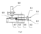
- the adjustable temperature controller 6 is a adjustable temperature controller made of thermal bimetal strip, which comprises a bimetal strip 6.7 and a temperature regulating shaft 6.8; a temperature overheat protector with temperature overheating protection function is also provided on the adjustable temperature controller 6, and the temperature overheat protector is used to cut off the circuit of electrothermal tube 3 in case of abnormal temperature control of the adjustable temperature controller 6, which plays the function of safety protection.
- said temperature overheat protector is an arched spring piece 6.1, which is provided on the adjustable temperature controller 6 and is connected in series with a pair of temperature control switch contacts 6.5.
- An eutectic tin alloy welding spot 6.2 is used to weld the free end of the arched spring piece 6.1 with the free end of a first wiring terminal 6.3 for the purpose of conducting, the fixed end of the first wiring terminal 6.3 is separated from the fixed end of the arched spring piece 6.1 by means of a mica washer 6.6; the first wiring terminal 6.3 and a second wiring terminal 6.4 are respectively connected with the electrothermal tube 3 and the power input end; through a spring assembly 6.9 in the adjustable temperature controller 6, a pair of temperature control switch contacts 6.5, the arched spring piece 6.1 and the first wiring terminal 6.3, the second wiring terminal 6.4 forms electrical connection with the electrothermal tube 3.
- the preset dangerous temperature for the stainless steel soleplate 1 of the electric iron is 360°C.
- the temperature of the soleplate rises to the melting point temperature 240°C of the eutectic tin alloy welding spot, the eutectic tin alloy welding spot 6.2 melts, so that the arched spring piece 6.1 springs open and thus switches off the circuit connected from the power input end to the electrothermal tube 3, playing the function of safety protection.
- Fig 4 is the structural diagram of the embodiment 2 where the cordless oil-storage type electric iron with contact pin is placed on a preheating power socket;
- Fig 7 is the schematic diagram of the circuit structure as disclosed in the embodiment 2.
- an electric iron is provided with a power line and a plug.
- the electric iron For the purpose of ironing operation, it is necessary to insert the power line on the power supply socket, so that the electric iron can generate heat and work.
- the dragging and shackling of the power line cause inconveniences in use and operation of the electric iron.
- the clothing may be contaminated by the pollutions on the power line.
- a cordless electric iron is used, the temperature of electric iron drops very quickly due to small thermal capacity of the traditional metallic soleplate, so that it is necessary to preheat the electric iron frequently, which causes inconvenience.
- an oil-storage type electric iron is used, since the soleplate of oil storage type iron has big thermal capacity, there will be longer effective operation time after a preheating.
- a pair of contact pins 11 in the cordless oil-storage type electric iron with contact pin are provided on a terminal box 30 at the rear end of the electric iron;
- one end of contact pins 11 in the shell is respectively connected with such elements as the electrothermal tube 3 and the adjustable temperature controller 6 through the wiring terminal 12, namely one end of one of a pair of contact pins 11 is connected with the electrothermal tube 3 through the wiring terminal 12, one end of another contact pin 11 is connected with the adjustable temperature controller 6 through the wiring terminal 12, and another end of the contact pin is an extending end, which extends out of the terminal box 30 of the oil-storage type electric iron and is connected with the power supply device.
- a contact spring piece13 is composed of a pair of thin bronze strips corresponding to the contact pins 11 , and its free end is connected with the extending end of the contact pin 11 through coordinated contact. To guarantee satisfactory electrical contact, it is feasible to provide silvered or compound silvered contact surface on the end surface of the extending end of the contact pin 11 and on the surface of the contact spring piece 13.
- the electrical connection safety device comprises a pushing boss 14, a movable pressing block 15, a fixed plate 16 and a movable spring piece 1 7.
- the pushing boss 14 is provided on the terminal box 30 under the back of electric iron, which is nearby a pair of contact pins 11, the movable pressing block 15 is provided on the preheating power socket, a resetting torsion spring 18 is provided on the pivot of the movable pressing block 15, the ends of a pair of fixed plates 16 are respectively connected with the fixed ends of a pair of contact spring pieces 13, a first electrical contact 19 is provided on the another end of a pair of fixed plates 16.
- the movable spring pieces 17 are a pair of thin bronze strips, the fixed ends of the movable spring pieces 17 are respectively connected with the power wiring terminals 21 at two poles of the power line 22( zero line /live wire), its another end is a free end, on which a second electrical contact 20 is provided.
- the initial position of the free end of the movable spring piece 1 7 is set above the free end of the fixed plate 16, so that the second electrical contact 20 is separated from the first electrical contact 19.
- the pushing boss 14 continues to push the movable pressing block 15 to move downwards and push downwards the movable spring piece 17, until the second electrical contact 20 contacts with the first electrical contact 19, so that the heating tube 3 of the cordless electric iron is powered on.
- the movable spring piece 17 Because the movable spring piece 17 has lost the pushing force of the movable pressing block 15 when the electric iron leaves from the preheating power socket, the movable spring piece 17 moves upwards under the effect of the elastic force generated by the resetting torsion spring 18 and the movable spring piece 17, so that the second electrical contact 20 is disengaged from the first electrical contact 19, the power supply is disconnected and the contact spring piece 13 is powered off. At this moment, under the effect of elastic force, the contact spring piece 13 pushes the contact pin 11 to move up simultaneously, so that the contact pin 11 has been under power off condition although the contact pin 11 has not been disengaged from the contact spring piece 13. Therefore, when the contact pin 11 is disengaged from the contact spring piece 13, arc phenomenon will unlikely occur, the resetting torsion spring 18 resets the movable pressing block 15 and the movable spring piece 17 returns to its initial position.
- the contact pin 11 firstly contacts with the contact spring piece 13, and subsequently the movable pressing block 15 presses down the movable spring piece 17, so that the first electrical contact 19 contacts with the second electrical contact 20, and the power supply is turned on.
- the movable pressing block 15 firstly loosens the movable spring piece 17, so that the first electrical contact 19 is separated from the second electrical contact 20, the power supply is turned off, and in turn the contact pin 11 is separated from the contact spring piece 13.
- Fig 5.1 is the schematic diagram of the side section of the preheating power socket as disclosed in the embodiment 2
- Fig 5.2 is the schematic diagram of the upper section and local section of the preheating power socket as disclosed in the embodiment 2.
- the preheating power socket also comprises a bracket seat 13 and a thermal insulation cushion 24, which is used for skid-proof and heat-insulated when the electric iron is placed, the thermal insulation cushion 24 can be made of soft silica gel.
- the inclination angle of the table of the bracket seat 23 is 15 ⁇ 45°, so that when an electric iron is placed on the bracket seat 23, the contact pins 11 can reliably contact with the contact spring piece 13.
- the said electrical-connection safety device can be used to further improve the safety and service life of electric iron and to generate the effect of ensuring the safety of a power network.
- Fig 4 is the structural diagram of the reversible thermopaint sprayed in the periphery of the soleplate of electric iron.
- a reversible thermopaint 25 is sprayed on the exposed side around the stainless steel soleplate 1 of the electric iron; the reversible thermopaint 25 can be composed of one, two or three kinds of coatings which spray the whole cycle, part or pattern shape.
- the reversible thermopaint 25 can be sprayed in the periphery of the soleplate 1 and is in black at temperature. In the process of preheating the soleplate, the color of the coating turns from black into red.
- the temperature controller acts, and the heating indication lamp 34 of heating tube is off; in the operation and use of a cordless electric iron, the temperature of the soleplate gradually drops.
- the temperature of the soleplate has dropped to the temperature at which the color of the coating changes, the color of the coating turns from red into black, prompting that it is necessary to replace the preheating power socket for heating.
- thermopaints in three different colors can be provided, with their color-changing temperatures being 80°C, 130°C and 180°C respectively. If the coating with color-changing temperature of 80°C changes color while the coating with color-changing of 130°C does not change color, it is indicated that the temperature of the soleplate is within the range of 80-130 °C; If the coating with color-changing temperature of 130°C changes color while the coating with color-changing of 180°C does not change color, it is indicated that the temperature of the soleplate is within the range of 130-180°C; If the coating with color-changing temperature of 180°C changes color, it is indicated that the temperature of the soleplate is above 180°C; if all the paints have not changed color, it is indicated that the temperature of the soleplate is below 80°C.
- thermopaint it is feasible to spray the reversible thermopaint into pictorial trademark or text or other kinds of patterns.
- thermopaints it is feasible to adopt reversible color-changing thermopaints to display temperatures, generating such effects as a simple and visual, facilitate operation and decoration.
- Fig 6 is the structural diagram of the embodiment 3 of the present invention.
- the electric iron also comprises a steam-generating device, the steam generating device comprises a second closed shell 26 for accommodating water and steam, a steam conduit 27, a second electrothermal tube 28 and a temperature-limiting temperature controller 29; the second closed shell 26 is permanently connected with a mounting seat 10 inside the flat ironing part; a water filling nozzle sealed tube 31 and a cock 32 are provided on the second closed shell 26, the second electrothermal tube 28 is provided inside the second closed shell 26, a steam inlet 27.1 is provided on the upper end of the steam conduit 27, the lower port 27.2 of the steam conduit extends out of the second closed shell 26; a steam-spray chamber 27.3 is provided between the upper casing plate 2 and the soleplate 1 of the flat ironing part, a steam-spray hole 1.1 is provided on the stainless steel soleplate 1 , and the position of the steam-spray hole 1.1 corresponds to the position of the steam-spray chamber.
- the steam generating device
- the steam indicating switch 33 may be turned on, so that the second electrothermal tube 28 heats the water in the second closed shell 26 to boil and generate steam; after the steam has entered the steam inlet 27.1 above the steam conduit 27, the steam enters the steam-spray chamber 27.3 from the lower port 27.2 and then is sprayed out from the steam-spray hole 1.1 above the soleplate of the iron.
- An oil-storage type electric iron can be designed as a cordless or a core dry ironing type electric iron without steam generation part, also can be designed as a cordless or a core team type electric iron with steam generation part. In general cases, it is advisable to adopt cordless type for dry ironing electric iron and adopt electric iron with core for steam type electric iron.
- the oil-storage type electric iron provided by the present invention has such advantages as temperature uniformity, convenient operation, energy saving, safety use and high economic value and use value and breaks through the mode of the traditional electric iron.
Landscapes
- Engineering & Computer Science (AREA)
- Textile Engineering (AREA)
- Irons (AREA)
Description
- The present invention relates to the field of electric irons of domestic appliance, and in particular relates to an oil-storage type electric iron.
- In the prior art, the soleplate of an domestic electric iron is generally designed as a die-casted aluminium soleplate integrated with the heating tube, and an adjustable temperature controller mounted on the upper surface of soleplate is used to control the operations of heating tube, so as to control and regulate the temperature on the bottom surface of the soleplate of electric iron. Such electric iron has the following disadvantages: the specific-heat capacity of aluminium product is relatively lower, the thermal capacity of the soleplate of electric iron is relatively smaller, so that the first-stroke temperature at the starting time is high, the temperature fluctuation in the operation of electric iron is high, and the stability of operating temperature is poor, so that the use safety and ironing quality of electric iron are affected; in order to increase the thermal capacity of soleplate, it is generally necessary to increase the weight of the aluminium material for soleplate, which causes higher cost and energy consumption in production. Furthermore, the operation of electric iron is not sufficiently flexible due to increased weight. Furthermore, the surface abrasion resistance of the cast-aluminum soleplate is poor, so that it is necessary to spray a wearing coat on the bottom surface of soleplate. Such wearing coat has poor wearing property and may be easily scraped and worn. If the soleplate is wrapped with a stainless steel plate or an additional thin layer of wear resistant soleplate, such problems as lower thermal efficiency and higher wear will occur. Furthermore, said electric iron also has such problems as uneven temperature distribution on the bottom surface of soleplate, higher temperature at the position corresponding to the heating tube and lower temperature at other positions. However, since domestic electric irons generally adopt dynamic ironing mode, so that the uneven surface temperature of soleplate causes less influence. Therefore, in the field of domestic iron irons, an electrothermal tube is habitually used to directly heat the metal plate. Furthermore, all the traditional electric irons are designed as electric irons with core (with power line). In the practical use, due to the dragging operation of power line and the limit in the distance from power supply, more convenient and comprehensive use of the traditional electric irons are affected.
- An oil-storage type electric iron according to the preamble of
claim 1 is disclosed in documentDE 3544506 . DocumentUS 1636359 discloses an oil-storage type electric iron according to the state of the art where the heating temperature is defined by the insulating materials from which the iron is made. - With the view of said problems, it is the technical object of the present invention to provide an oil-storage type electric iron, which is featured by high stability and evenness of working temperature, convenient, flexible and safe operation and long service life and can reduce material costs and energy consumption in production and thus save resources.
- More specifically, the present invention provides an oil-storage type electric iron, comprising a flat ironing part and an
adjustable temperature controller 6, wherein the flat ironing part comprises astainless steel soleplate 1, anupper casing plate 2, anelectrothermal tube 3 and aheat conducting oil 4; thestainless steel soleplate 1 and theupper casing plate 2 form a closed shell; and the closed shell is internally provided with theelectrothermal tube 3 and theheat conducting oil 4. - Preferably, the closed shell is also internally provided with an
electrothermal tube bracket 5 and a temperaturecontroller mounting seat 7; theadjustable temperature controller 6 is provided on the temperaturecontroller mounting seat 7, and theelectrothermal tube bracket 5 is permanently connected with theelectrothermal tube 3 and the temperaturecontroller mounting seat 7 respectively. - Preferably, the
adjustable temperature controller 6 is an adjustable temperature controller made of thermal bimetal strip. - According to the invention, the adjustable temperature controller comprises a temperature overheat protector. The temperature overheat protector comprises a pair of temperature control switch contacts 6.5 provided on the
adjustable temperature controller 6; an arched spring piece 6.1 is connected in series with the temperature control switch contacts 6.5, an eutectic tin alloy welding spot 6.2 is used to weld the free end of the arched spring piece 6.1 with the free end of a first wiring terminal 6.3 for the purpose of conducting, the fixed end of the first wiring terminal 6.3 is separated from the fixed end of the arched spring piece 6.1 by means of a mica washer 6.6; the first wiring terminal 6.3 and a second wiring terminal 6.4 are respectively connected with theelectrothermal tube 3 and the power input end. - Preferably, the oil-storage type electric iron also comprises a pair of
contact pins 11 , thecontact pins 11 are provided under aterminal box 30 at the rear end of the oil-storage type electric iron, the ends of thecontact pins 11 1 are respectively connected with theelectrothermal tube 3 and theadjustable temperature controller 6 through a pair ofwiring terminals 12 inside theterminal box 30, and another end of thecontact pins 11 is an extending end which extends from theterminal box 30 and is connected with a power supply device. - Preferably, The power supply device is a preheating power socket, which comprises a pair of
contact spring pieces 13, a pair ofpower wiring terminals 21 and apower line 22; the free end of thecontact spring piece 13 is contiguously connected with the extending end of thecontact pin 11. the surface of thecontact spring piece 13 and the surface of the extending end of thecontact pin 11 are respectively provided with a silver coating or a compound silver coating. - The oil-storage type electric iron and the preheating power socket also comprise an electrical connection safety device, the electrical connection safety device comprises a pushing
boss 14, a movablepressing block 15, afixed plate 16 and amovable spring piece 17; the pushingboss 14 is provided on theterminal box 30 at the rear end of the electric iron, the movablepressing block 15 is provided on the preheating power socket; a resettingtorsion spring 18 is provided on the pivot of the movablepressing block 15; one end of thefixed plate 16 is connected with the fixed end of acontact spring piece 13, and a firstelectrical contact 19 is provided on the another end of thefixed plate 16; one end of themovable spring piece 17 is connected with thepower wiring terminal 21 , and a secondelectrical contact 20 is provided on the another end of themovable spring piece 17; when the oil-storage type electric iron is placed in the preheating power socket, the extending end of thecontact pin 11 is connected with the free end of thecontact spring piece 13, the pushingboss 14 pushes the movablepressing block 15 to move downwards and press down themovable spring piece 17, so that the secondelectrical contact 20 of the movable spring piecel7 contacts with the firstelectrical contact 19 of fixedplate 16; The preheating power socket also comprises abracket seat 23 and athermal insulation cushion 24; the inclination angle of the table of thebracket seat 23 is 15°-45°, and thethermal insulation cushion 24 is made of soft silica gel. - A coating layer is provided in the whole/partial periphery on the side of the closed shell, and the coating layer is composed of one, two or three kinds of
reversible thermopaints 25 which can change colors at specific temperature. - The oil-storage type electric iron also comprises a steam-generating device, and the steam-generating device comprises a second closed
shell 26, asteam conduit 27, a secondelectrothermal tube 28 and a temperature-limitingtype temperature controller 29; water and steam are provided in the second closedshell 26. - The second closed
shell 26 is provided above the flat ironing part and is permanently connected with the built-inmounting seat 10 in the closed shell; a water filling nozzle sealedtube 31 and acock 32 are provided on the second closedshell 26, the secondelectrothermal tube 28 is provided inside the second closedshell 26, a steam inlet 27.1 is provided on the upper end of thesteam conduit 27, a lower port 27.2 of thesteam conduit 27 extends out of the second closedshell 26; a steam-spray chamber 27.3 is provided between theupper casing plate 2 and thestainless steel soleplate 1 , a steam-spray hole 1.1 is provided on thestainless steel soleplate 1 , and the position of the steam-spray hole 1.1 corresponds to the position of the steam-spray chamber 27.3. - The beneficial effects of the present invention as follows :
- The present invention breaks through the traditional use mode of electric iron, and puts forward a solution to effectively solve such problems as low thermal capacity, poor temperature stability, temperature uniformity, durability and safety of the soleplate of electric iron. In addition, the cordless electric iron is adopted to provide more convenient and safe operations. The present invention can also be used in combination with the steam-generating device to further improve the functions of electric iron.
- The technical solution of the present invention is described in detail in combination with the attached figures and the specific embodiments.
-
-
FIG 1 is the structural diagram of theembodiment 1 of the present invention; -
Fig 2 is the schematic diagram of the position of an electrothermal tube in the soleplate of the electric iron as disclosed in theembodiment 1 of the present invention; -
Fig 3 is the structural diagram of the adjustable temperature controller with the temperature overheat protector as shown inFig 1 ; -
Fig 4 is the structural diagram of the cordless electric iron with the contact pins and the preheating power socket as disclosed in theembodiment 2 of the present invention; -
Fig 5.1 is the schematic diagram of the side section of the preheating power socket as disclosed in theembodiment 2 of the present invention; -
Fig 5.2 is the schematic diagram of the upper section and local section of the preheating power socket as disclosed in theembodiment 2 of the present invention; -
Fig 6 is the structural diagram of the steam oil-storage type electric iron as disclosed in theembodiment 3 of the present invention; -
Fig 7 is the schematic diagram of the circuit structure as disclosed in theembodiment 2 of the present invention. -
- 1. Stainless steel soleplate 1.1. Steam-
spray hole 2. Upper casing plate - 3.
Electrothermal tube 4. Heat conducting oil - 5.
Electrothermal tube bracket 6. Adjustable temperature controller - 6.1. Arched spring piece 6.2. Eutectic tin alloy welding spot
- 6.3. First wiring terminal 6.4. Second wiring terminal
- 6.5. Temperature control switch contact 6.6.Mica washer
- 6.7. Bimetal strip 6.8. Temperature regulating shaft
- 6.9.
Spring assembly 7. Temperature controller mounting seat - 8. Reinforcing rib 9.
Shell 10. Mounting seat - 11.
Contact pin 12. Wiringterminal 13. Contact spring piece - 14. Pushing
boss 15. Movablepressing block 16. Fixed plate - 17.
Movable spring piece 18. Resetting torsion spring - 19. First
electrical contact 20. Second electrical contact - 21.
Power wiring terminal 22. Power line 23.Bracket seat - 24.
Thermal insulation cushion 25. Reversible thermopaint - 26. Second closed shell 27.Steam conduit 27.1. Steam inlet
- 27.2. Lower port 27.3. Steam-spray chamber
- 28. Second electrothermal tube
- 29. Temperature-limiting temperature controller
- 30.
Terminal box 31. Water filling nozzle sealed tube - 32.
Cock 33.Steam indicating switch 34. Heating indication lamp. -
Fig 1 is the structural diagram of theembodiment 1 of the present invention; As shown inFig 1 , the flat ironing part of the electric iron comprises astainless steel soleplate 1, anupper casing plate 2, anelectrothermal tube 3, aheat conducting oil 4, anelectrothermal tube bracket 5, a temperaturecontroller mounting seat 7 and a mountingseat 10. Thesoleplate 1 and theupper casing plate 2 form a closed shell. The closed shell is internally provided with theelectrothermal tube 3 and filled with high-temperature resistantheat conducting oil 4. However, the closed shell is not completely filled with theheat conducting oil 4, so as to reserve the space for expansion of heat conducting oil at high temperature. - Generally, the specific-heat capacity of heat conducting oil is 2-3 KJ/Kg°C, while the specific-heat capacity of aluminum is merely 0.88KJ/Kg°C. With the same weight, the thermal capacity of heat conducting oil is 2.5-3.5 times as much as that of aluminum. Since the media of heat conducting oil is heated by means of heating tube and the thermal capacity is transferred to the whole surface of the soleplate, as compared with the case where the electrothermal tube is used to directly heat the aluminium soleplate, the temperature uniformity of the soleplate of electric iron is improved. Therefore, if the oil-storage type electric iron is adopted, it is feasible to increase the thermal capacity of the soleplate of electric iron by several times against the aluminium-made metallic soleplate, so that such problems as poor temperature stability and temperature uniformity and high temperature fluctuation on the ironing bottom surface of electric iron can be solved. With smaller working temperature fluctuation, lower action frequency of temperature controller and lower thermal shock at the time of starting up, the service life of electric iron can be effectively extended.
- The
stainless steel soleplate 1 can be made of stainless steel plate in thickness of 1.2-2.5 mm, which is punched into a disk-shaped soleplate of iron. Theupper casing plate 2 can be made of stainless steel plate in thickness of 0.5-1 mm, which is punched into a disk-shape matching with the periphery of thestainless steel soleplate 1. Since the stainless steel plate has satisfactory corrosion resistance and wearability, the polished soleplate is durable in use and is uneasily damaged in collision. As compared with the cast aluminum plate sprayed with wear-resistant coating or wrapped with stainless steel surface, the polished soleplate can effectively improve the durability of electric iron and reduce the material costs and energy consumption in production. Since heat conducting oil is used to transfer heat, the surface tem perature of the soleplate is even and stable without local high temperature, so that such problems as local colour change on the surface of the stainless steel soleplate and plastering of fabric will not occur, which often occur on the surface of the cast aluminum soleplate. - Several reinforcing
ribs 8, which emboss inwards, are provided on theupper casing plate 2, so as to strengthen the rigidity of theupper casing plate 2 on the one hand and to play the function of wave elimination on the other hand, namely to eliminate the surge that may be generated by the heat conducting oil in the movement of electric iron. -
Fig 2 is the schematic diagram of the position of anelectrothermal tube 3 in the soleplate of the electric iron. As shown inFig 1 in combination withFig 2 , theelectrothermal tube 3 is horizontally placed and immersed in theheat conducting oil 4 in the closed shell formed by thestainless steel soleplate 1 and theupper casing plate 2; theadjustable temperature controller 6 is provided on the temperaturecontroller mounting seat 7; theelectrothermal tube bracket 5 is permanently connected with theelectrothermal tube 3 and the temperaturecontroller mounting seat 7 respectively; Theelectrothermal tube 3 is approximate to U-shaped tube; both ends of theelectrothermal tube bracket 5 firmly hold theelectrothermal tube 3; the middle section of theelectrothermal tube bracket 5 sockets the temperaturecontroller mounting seat 7, and the temperaturecontroller mounting seat 7 makes theelectrothermal tube bracket 5 firmly attached theupper casing plate 2. Since theelectrothermal tube bracket 5 is connected with theelectrothermal tube 3 and is firmly attached onto the upper end surface of the temperaturecontroller mounting seat 7, the reaction sensitivity of theadjustable temperature controller 6 to the temperature of theelectrothermal tube 3 can be improved, and temperature control can be performed in time, so that the temperature of theheat conducting oil 4 in the closed shell becomes even stable. -
Fig 3 is the schematic diagram of theadjustable temperature controller 6. Theadjustable temperature controller 6 is a adjustable temperature controller made of thermal bimetal strip, which comprises a bimetal strip 6.7 and a temperature regulating shaft 6.8; a temperature overheat protector with temperature overheating protection function is also provided on theadjustable temperature controller 6, and the temperature overheat protector is used to cut off the circuit ofelectrothermal tube 3 in case of abnormal temperature control of theadjustable temperature controller 6, which plays the function of safety protection. As shown inFig 3 in combination withFig 7 , said temperature overheat protector is an arched spring piece 6.1, which is provided on theadjustable temperature controller 6 and is connected in series with a pair of temperature control switch contacts 6.5. - An eutectic tin alloy welding spot 6.2 is used to weld the free end of the arched spring piece 6.1 with the free end of a first wiring terminal 6.3 for the purpose of conducting, the fixed end of the first wiring terminal 6.3 is separated from the fixed end of the arched spring piece 6.1 by means of a mica washer 6.6; the first wiring terminal 6.3 and a second wiring terminal 6.4 are respectively connected with the
electrothermal tube 3 and the power input end; through a spring assembly 6.9 in theadjustable temperature controller 6, a pair of temperature control switch contacts 6.5, the arched spring piece 6.1 and the first wiring terminal 6.3, the second wiring terminal 6.4 forms electrical connection with theelectrothermal tube 3. - The preset dangerous temperature for the
stainless steel soleplate 1 of the electric iron is 360°C. When the temperature of the soleplate rises to the melting point temperature 240°C of the eutectic tin alloy welding spot, the eutectic tin alloy welding spot 6.2 melts, so that the arched spring piece 6.1 springs open and thus switches off the circuit connected from the power input end to theelectrothermal tube 3, playing the function of safety protection. -
Fig 4 is the structural diagram of theembodiment 2 where the cordless oil-storage type electric iron with contact pin is placed on a preheating power socket;Fig 7 is the schematic diagram of the circuit structure as disclosed in theembodiment 2. - In general, an electric iron is provided with a power line and a plug. For the purpose of ironing operation, it is necessary to insert the power line on the power supply socket, so that the electric iron can generate heat and work. However, the dragging and shackling of the power line cause inconveniences in use and operation of the electric iron. Sometimes, the clothing may be contaminated by the pollutions on the power line. If a cordless electric iron is used, the temperature of electric iron drops very quickly due to small thermal capacity of the traditional metallic soleplate, so that it is necessary to preheat the electric iron frequently, which causes inconvenience. If an oil-storage type electric iron is used, since the soleplate of oil storage type iron has big thermal capacity, there will be longer effective operation time after a preheating. Therefore, it is especially advisable to adopt a cordless electric iron. When the power supply is relatively far from the clothing to be ironed, there is no need to drag the power line, the operation process becomes more flexible and clean, and the range of uses and functions of the electric iron can be greatly extended. Furthermore, being able to operate in uncharged state, the electric iron is safer and energy-saving.
- As shown in
Fig 4 in combination withFig 7 , a pair of contact pins 11 in the cordless oil-storage type electric iron with contact pin are provided on aterminal box 30 at the rear end of the electric iron;, one end of contact pins 11 in the shell is respectively connected with such elements as theelectrothermal tube 3 and theadjustable temperature controller 6 through thewiring terminal 12, namely one end of one of a pair of contact pins 11 is connected with theelectrothermal tube 3 through thewiring terminal 12, one end of anothercontact pin 11 is connected with theadjustable temperature controller 6 through thewiring terminal 12, and another end of the contact pin is an extending end, which extends out of theterminal box 30 of the oil-storage type electric iron and is connected with the power supply device. A contact spring piece13 is composed of a pair of thin bronze strips corresponding to the contact pins 11 , and its free end is connected with the extending end of thecontact pin 11 through coordinated contact. To guarantee satisfactory electrical contact, it is feasible to provide silvered or compound silvered contact surface on the end surface of the extending end of thecontact pin 11 and on the surface of thecontact spring piece 13. - In order to prevent the safety problem from being caused by an electric iron, which contacts with an exposed
contact spring piece 13 before it is placed on the preheating power socket, and an electrical connection safety device is adopted on the electrical connection position of the electric iron and the preheating power socket in this embodiment. As shown inFig 4 , the electrical connection safety device comprises a pushingboss 14, a movablepressing block 15, a fixedplate 16 and amovable spring piece 1 7. The pushingboss 14 is provided on theterminal box 30 under the back of electric iron, which is nearby a pair of contact pins 11, the movablepressing block 15 is provided on the preheating power socket, a resettingtorsion spring 18 is provided on the pivot of the movablepressing block 15, the ends of a pair of fixedplates 16 are respectively connected with the fixed ends of a pair ofcontact spring pieces 13, a firstelectrical contact 19 is provided on the another end of a pair of fixedplates 16. Themovable spring pieces 17 are a pair of thin bronze strips, the fixed ends of themovable spring pieces 17 are respectively connected with thepower wiring terminals 21 at two poles of the power line 22( zero line /live wire), its another end is a free end, on which a secondelectrical contact 20 is provided. The initial position of the free end of themovable spring piece 1 7 is set above the free end of the fixedplate 16, so that the secondelectrical contact 20 is separated from the firstelectrical contact 19. - As shown in
Fig 4 in combination withFig 7 , when the electric iron is placed on the preheating power socket, the extending end of thecontact pin 11 firstly contacts with the free end of thecontact spring piece 13. At this moment, the movablepressing block 15 has not been pressed downwards in place, and the firstelectrical contact 19 does not contact with the secondelectrical contact 20, namely, before thecontact pin 11 contacts withcontact spring piece 13 and at the moment when they contact, thecontact spring piece 13 is uncharged. Therefore, it is feasible to prevent electric shock when a operator touches the exposedcontact spring piece 13, prevent arc discharge at the moment of contact and to avoid the arc erosion from generating adverse impact on the service life and electrical contact properties of contacted elements as well as the electromagnet interference caused by the electric arc to power network. After thecontact pin 11 has contacted with thecontact spring piece 13, the pushingboss 14 continues to push the movablepressing block 15 to move downwards and push downwards themovable spring piece 17, until the secondelectrical contact 20 contacts with the firstelectrical contact 19, so that theheating tube 3 of the cordless electric iron is powered on. - Because the
movable spring piece 17 has lost the pushing force of the movablepressing block 15 when the electric iron leaves from the preheating power socket, themovable spring piece 17 moves upwards under the effect of the elastic force generated by the resettingtorsion spring 18 and themovable spring piece 17, so that the secondelectrical contact 20 is disengaged from the firstelectrical contact 19, the power supply is disconnected and thecontact spring piece 13 is powered off. At this moment, under the effect of elastic force, thecontact spring piece 13 pushes thecontact pin 11 to move up simultaneously, so that thecontact pin 11 has been under power off condition although thecontact pin 11 has not been disengaged from thecontact spring piece 13. Therefore, when thecontact pin 11 is disengaged from thecontact spring piece 13, arc phenomenon will unlikely occur, the resettingtorsion spring 18 resets the movablepressing block 15 and themovable spring piece 17 returns to its initial position. - In order to guarantee that the
contact spring piece 13 is uncharged whenever thecontact pin 11 contacts with or separates from thecontact spring piece 13, it is necessary to make the extension height of thecontact pin 11 and the contact stroke in coordination with thecontact spring piece 13 exceed the height of the pushingboss 14 at the tail of electric iron as well as the stroke in coordination with the movable pushing 15, so that when the movablepressing block 15 in coordination with thepressing boss 14 is pressing on the firstelectrical contact 19 and the secondelectrical contact 20, the time point whenelectrical contact 19 is connected with the secondelectrical contact 20, is posterior to the time point when thecontact pin 11 is connected with thecontact spring piece 13, and the time point whenelectrical contact 19 is disconnected with the secondelectrical contact 20, is ahead of the time point when thecontact pin 11 is disconnected with thecontact spring piece 13. That is to say, when a cordless electric iron is placed, thecontact pin 11 firstly contacts with thecontact spring piece 13, and subsequently the movablepressing block 15 presses down themovable spring piece 17, so that the firstelectrical contact 19 contacts with the secondelectrical contact 20, and the power supply is turned on. When the cordless electric iron is removed, the movablepressing block 15 firstly loosens themovable spring piece 17, so that the firstelectrical contact 19 is separated from the secondelectrical contact 20, the power supply is turned off, and in turn thecontact pin 11 is separated from thecontact spring piece 13. -
Fig 5.1 is the schematic diagram of the side section of the preheating power socket as disclosed in theembodiment 2,Fig 5.2 is the schematic diagram of the upper section and local section of the preheating power socket as disclosed in theembodiment 2. As shown inFig 5.1 , the preheating power socket also comprises abracket seat 13 and athermal insulation cushion 24, which is used for skid-proof and heat-insulated when the electric iron is placed, thethermal insulation cushion 24 can be made of soft silica gel. The inclination angle of the table of thebracket seat 23 is 15∼45°, so that when an electric iron is placed on thebracket seat 23, the contact pins 11 can reliably contact with thecontact spring piece 13. - The said electrical-connection safety device can be used to further improve the safety and service life of electric iron and to generate the effect of ensuring the safety of a power network.
-
Fig 4 is the structural diagram of the reversible thermopaint sprayed in the periphery of the soleplate of electric iron. As shown inFig 4 , areversible thermopaint 25 is sprayed on the exposed side around thestainless steel soleplate 1 of the electric iron; thereversible thermopaint 25 can be composed of one, two or three kinds of coatings which spray the whole cycle, part or pattern shape. For example, thereversible thermopaint 25 can be sprayed in the periphery of thesoleplate 1 and is in black at temperature. In the process of preheating the soleplate, the color of the coating turns from black into red. When the temperature of the soleplate has reached the preset value, the temperature controller acts, and theheating indication lamp 34 of heating tube is off; in the operation and use of a cordless electric iron, the temperature of the soleplate gradually drops. When the temperature of the soleplate has dropped to the temperature at which the color of the coating changes, the color of the coating turns from red into black, prompting that it is necessary to replace the preheating power socket for heating. For example, it is feasible to spray reversible thermopaints in different colors in the periphery of the soleplate, so as to reflect diversified temperature specifications and form diversified temperature displaying functions. For example, three kinds of reversible thermopaints in three different colors can be provided, with their color-changing temperatures being 80°C, 130°C and 180°C respectively. If the coating with color-changing temperature of 80°C changes color while the coating with color-changing of 130°C does not change color, it is indicated that the temperature of the soleplate is within the range of 80-130 °C; If the coating with color-changing temperature of 130°C changes color while the coating with color-changing of 180°C does not change color, it is indicated that the temperature of the soleplate is within the range of 130-180°C; If the coating with color-changing temperature of 180°C changes color, it is indicated that the temperature of the soleplate is above 180°C; if all the paints have not changed color, it is indicated that the temperature of the soleplate is below 80°C. It is also feasible to spray the reversible thermopaint into pictorial trademark or text or other kinds of patterns. In a word, it is feasible to adopt reversible color-changing thermopaints to display temperatures, generating such effects as a simple and visual, facilitate operation and decoration. -
Fig 6 is the structural diagram of theembodiment 3 of the present invention. As shown inFig 6 , the electric iron also comprises a steam-generating device, the steam generating device comprises a secondclosed shell 26 for accommodating water and steam, asteam conduit 27, a secondelectrothermal tube 28 and a temperature-limitingtemperature controller 29; the secondclosed shell 26 is permanently connected with a mountingseat 10 inside the flat ironing part; a water filling nozzle sealedtube 31 and acock 32 are provided on the secondclosed shell 26, the secondelectrothermal tube 28 is provided inside the secondclosed shell 26, a steam inlet 27.1 is provided on the upper end of thesteam conduit 27, the lower port 27.2 of the steam conduit extends out of the secondclosed shell 26; a steam-spray chamber 27.3 is provided between theupper casing plate 2 and thesoleplate 1 of the flat ironing part, a steam-spray hole 1.1 is provided on thestainless steel soleplate 1 , and the position of the steam-spray hole 1.1 corresponds to the position of the steam-spray chamber. - When the electric iron is required to use steam for working, the
steam indicating switch 33 may be turned on, so that the secondelectrothermal tube 28 heats the water in the secondclosed shell 26 to boil and generate steam; after the steam has entered the steam inlet 27.1 above thesteam conduit 27, the steam enters the steam-spray chamber 27.3 from the lower port 27.2 and then is sprayed out from the steam-spray hole 1.1 above the soleplate of the iron. - An oil-storage type electric iron can be designed as a cordless or a core dry ironing type electric iron without steam generation part, also can be designed as a cordless or a core team type electric iron with steam generation part. In general cases, it is advisable to adopt cordless type for dry ironing electric iron and adopt electric iron with core for steam type electric iron.
- In conclusion, the oil-storage type electric iron provided by the present invention has such advantages as temperature uniformity, convenient operation, energy saving, safety use and high economic value and use value and breaks through the mode of the traditional electric iron.
Claims (10)
- An oil-storage type electric iron, comprising a flat ironing part and an adjustable temperature controller (6), wherein the flat ironing part comprises a stainless steel soleplate (1), an upper casing plate (2), an electrothermal tube (3) and a heat conducting oil (4); the stainless steel soleplate (1) and the upper casing plate (2) form a closed shell; and the closed shell is internally provided with the electrothermal tube (3) and the heat conducting oil (4), characterized in that the adjustable temperature controller (6) comprises a temperature overheat protector, wherein the temperature overheat protector comprises a pair of temperature control switch contacts (6.5) provided on the adjustable temperature controller (6); an arched spring piece (6.1) is connected in series with the temperature control switch contacts (6.5); an eutectic tin alloy welding spot (6.2) is used to weld the free end of the arched spring piece (6.1) with the free end of a first wiring terminal (6.3) for the purpose of conducting, the fixed end of the first wiring terminal (6.3) is separated from the fixed end of the arched spring piece (6.1) by means of a mica washer (6.6); the first wiring terminal (6.3) and a second wiring terminal (6.4) are respectively connected with the electrothermal tube (3) and the power input end.
- The oil storage type electric iron of claim 1 , wherein the closed shell is internally provided with an electrothermal tube bracket (5) and a temperature controller mounting seat (7); the adjustable temperature controller (6) is provided on the temperature controller mounting seat (7), and the electrothermal tube bracket (5) is permanently connected with the electrothermal tube (3) and the temperature controller mounting seat (7) respectively.
- The oil-storage type electric iron of claim 1 , wherein: the adjustable temperature controller (6) is an adjustable temperature controller made of thermal bimetal strip.
- An oil-storage type electric iron system, comprising the oil-storage type electric iron of claim 1 and a power supply device, wherein the oil-storage type electric iron also comprises a pair of contact pins (11), the contact pins (11) are provided under a terminal box (30) at the rear end of the oil-storage type electric iron, the ends of the contact pins (11) are respectively connected with the electrothermal tube (3) and the adjustable temperature controller (6) through a pair of wiring terminals (12) inside the terminal box (30), and another end of the contact pins (11) is an extending end which extends from the terminal box (30) and is connected with the power supply device.
- The oil-storage type electric iron system of claim 4, wherein the power supply device is a preheating power socket, which comprises a pair of contact spring pieces (13), a pair of power wiring terminals (21) and a power line (22); the free end of the contact spring pieces (13) is contiguously connected with the extending end of the contact pins (11), the surface of the contact spring piece (13) and the surface of the extending end of the contact pins (11) are respectively provided with a silver coating or a compound silver coating.
- The oil-storage type electric iron system of claim 5, wherein the oil-storage type electric iron and the preheating power socket also comprise an electrical connection safety device, the electrical connection safety device comprises a pushing boss (14), a movable pressing block (15), a fixed plate (16) and a movable spring piece (17); the pushing boss (14) is provided on the terminal box (30) at the rear end of the electric iron, the movable pressing block (15) is provided on the preheating power socket; a resetting torsion spring (18) is provided on the pivot of the movable pressing block (15); one end of the fixed plate (16) is connected with the fixed end of a contact spring piece (13), and a first electrical contact (19) is provided on the another end of the fixed plate (16); one end of the movable spring piece (17) is connected with the power wiring terminal (21), and a second electrical contact (20) is provided on the another end of the movable spring piece (17); when the oil-storage type electric iron is placed on the preheating power socket, the extending end of the contact pin (11) is connected with the free end of the contact spring piece (13), the pushing boss (14) pushes the movable pressing block (15) to move downwards and press down the movable spring piece (17), so that the second electrical contact (20) of the movable spring piece (17) contacts with the first electrical contact (19) of fixed plate (16).
- The oil-storage type electric iron system of claim 5 or 6, characterized in the following: the preheating power socket also comprises a bracket seat (23) and a thermal insulation cushion (24); the inclination angle of the table of the bracket seat (23) is 15∼45°.
- The oil-storage type electric iron of claim 1 or the oil-storage type electric iron system of claim 4, wherein a coating layer is provided in the whole/partial periphery on the side of the closed shell, and the coating layer is composed of one, two or three kinds of reversible thermopaints (25) which can change colors at specific temperature.
- The oil-storage type electric iron of claim 1 or the oil-storage type electric iron system of claim 4, wherein the oil-storage type electric iron also comprises a steam-generating device, and the steam-generating device comprises a second closed shell (26), a steam conduit (27), a second electrothermal tube (28) and a temperature-limiting type temperature controller (29); water and steam are provided in the second closed shell (26).
- The oil-storage type electric iron or the oil-storage type electric iron system of claim of claim 9, wherein the second closed shell (26) is provided above the flat ironing part and is permanently connected with a mounting seat (10) in the closed shell; a water filling nozzle sealed tube (31) and a cock (32) are provided on the second closed shell (26), the second electrothermal tube (28) is provided inside the second closed shell (26), a steam inlet (27.1) is provided on the upper end of the steam conduit (27), a lower port (27.2) of the steam conduit (27) extends out of the second closed shell (26); a steam-spray chamber (27.3) is provided between the upper casing plate (2) and the stainless steel soleplate (1), a steam-spray hole (1.1) is provided on the stainless steel soleplate (1), and the position of the steam-spray hole (1.1) corresponds to the position of the steam-spray chamber (27.3).
Applications Claiming Priority (2)
| Application Number | Priority Date | Filing Date | Title |
|---|---|---|---|
| CN2010102225069A CN101914846B (en) | 2010-07-06 | 2010-07-06 | Oil storage type electric iron |
| PCT/CN2010/075695 WO2012003650A1 (en) | 2010-07-06 | 2010-08-04 | Oil-storing type electric iron |
Publications (3)
| Publication Number | Publication Date |
|---|---|
| EP2471999A1 EP2471999A1 (en) | 2012-07-04 |
| EP2471999A4 EP2471999A4 (en) | 2013-07-03 |
| EP2471999B1 true EP2471999B1 (en) | 2015-02-25 |
Family
ID=43322471
Family Applications (1)
| Application Number | Title | Priority Date | Filing Date |
|---|---|---|---|
| EP10854309.1A Active EP2471999B1 (en) | 2010-07-06 | 2010-08-04 | Oil-storing type electric iron |
Country Status (5)
| Country | Link |
|---|---|
| US (1) | US8713824B2 (en) |
| EP (1) | EP2471999B1 (en) |
| JP (1) | JP5639711B2 (en) |
| CN (1) | CN101914846B (en) |
| WO (1) | WO2012003650A1 (en) |
Families Citing this family (7)
| Publication number | Priority date | Publication date | Assignee | Title |
|---|---|---|---|---|
| CN102156491B (en) * | 2011-03-11 | 2013-12-25 | 厦门升明电子有限公司 | Heating coil combined temperature controller |
| CN102454097B (en) * | 2011-12-30 | 2013-10-16 | 厦门优尔电器有限公司 | Electric iron capable of quickly raising and reducing temperature |
| CN104970709A (en) * | 2014-04-01 | 2015-10-14 | 漳州灿坤实业有限公司 | Bread maker and raw material storage unit thereof |
| EP3200865B1 (en) * | 2014-09-17 | 2020-12-23 | The Procter and Gamble Company | Skin care applicator |
| US10767305B2 (en) | 2016-05-02 | 2020-09-08 | Koninklijke Philips N.V. | Steam iron with thermal bridge arrangement |
| CN109445336B (en) * | 2018-10-30 | 2022-05-17 | 温州市麦特力克电器有限公司 | Switch control circuit and switch control system |
| CN109402997B (en) * | 2019-01-04 | 2024-04-19 | 宁波海歌电器有限公司 | Novel automatic steam-discharging iron |
Family Cites Families (39)
| Publication number | Priority date | Publication date | Assignee | Title |
|---|---|---|---|---|
| USRE17453E (en) * | 1929-10-08 | Fixatie o of correction | ||
| US1414007A (en) * | 1920-04-07 | 1922-04-25 | William H Berwick | Pressing element |
| US1636359A (en) * | 1921-12-15 | 1927-07-19 | Donald E Gates | Flatiron |
| US3263350A (en) * | 1958-12-18 | 1966-08-02 | Abraham Carlos Salomon | Electric steam iron |
| FR1251725A (en) * | 1960-03-18 | 1961-01-20 | Electric heater | |
| JPS4316635Y1 (en) * | 1964-08-15 | 1968-07-10 | ||
| JPS4864290A (en) * | 1971-12-16 | 1973-09-06 | ||
| JPS5077586U (en) * | 1973-11-15 | 1975-07-05 | ||
| JPS5215697A (en) * | 1975-07-25 | 1977-02-05 | Matsushita Electric Industrial Co Ltd | Iron |
| JPS5933357Y2 (en) * | 1979-04-13 | 1984-09-17 | 三洋電機株式会社 | steam iron |
| JPS5617099U (en) * | 1979-07-19 | 1981-02-14 | ||
| JPS608880Y2 (en) * | 1980-01-14 | 1985-03-29 | 東芝電気器具株式会社 | Cordless ironing device |
| JPS5786199U (en) * | 1980-11-14 | 1982-05-27 | ||
| JPS60163700A (en) * | 1984-02-03 | 1985-08-26 | 松下電器産業株式会社 | Temperture fuse apparatus of iron |
| FR2566439A1 (en) * | 1984-06-20 | 1985-12-27 | Rowenta Werke Gmbh | Device for achieving uniform transfer of heat inside an electrically heated clothes iron |
| JPS618098A (en) * | 1984-06-25 | 1986-01-14 | 松下電器産業株式会社 | iron |
| JPS61232900A (en) * | 1985-04-05 | 1986-10-17 | 松下電器産業株式会社 | iron |
| DE3544506A1 (en) * | 1985-12-17 | 1987-06-19 | Vinzenz Gaberszik | Currentless and cordless storage-type dry and steam-regulating iron |
| FR2606043B1 (en) * | 1986-10-31 | 1988-12-30 | Seb Sa | STEAM IRON |
| JPS6417600A (en) * | 1987-07-13 | 1989-01-20 | Alpine Electronics Inc | Winker switching operation detecting system |
| JPH01141698A (en) * | 1987-11-30 | 1989-06-02 | Matsushita Electric Ind Co Ltd | Cordless iron |
| JPH04122392A (en) * | 1990-09-14 | 1992-04-22 | Matsushita Electric Ind Co Ltd | Iron |
| BE1007457A3 (en) * | 1993-08-23 | 1995-07-04 | Philips Electronics Nv | Iron with sliding low. |
| JP3275539B2 (en) * | 1994-06-10 | 2002-04-15 | 松下電器産業株式会社 | Thermostat for ironing |
| JP3375211B2 (en) * | 1994-09-30 | 2003-02-10 | 東芝ホームテクノ株式会社 | Electric iron |
| JP3292192B2 (en) * | 1994-11-29 | 2002-06-17 | 松下電器産業株式会社 | Cordless iron |
| JPH0938398A (en) * | 1995-07-31 | 1997-02-10 | Sanyo Electric Co Ltd | Iron |
| JP3265936B2 (en) * | 1995-08-21 | 2002-03-18 | 松下電器産業株式会社 | Cordless iron |
| JPH09117600A (en) | 1995-10-25 | 1997-05-06 | Matsushita Electric Ind Co Ltd | Heat storage device and heat storage iron using the same |
| JPH10277299A (en) * | 1997-04-10 | 1998-10-20 | Matsushita Electric Ind Co Ltd | Cordless iron |
| JP2001096100A (en) * | 1999-09-30 | 2001-04-10 | Matsushita Electric Ind Co Ltd | Cordless iron |
| JP2001204996A (en) * | 2000-01-25 | 2001-07-31 | Toshiba Home Technology Corp | Iron |
| JP4073634B2 (en) * | 2001-02-19 | 2008-04-09 | 松下電器産業株式会社 | Iron |
| FR2837220B1 (en) * | 2002-03-13 | 2004-08-06 | Rowenta Werke Gmbh | IRON SOLE WITH HARDENED AND COATED SURFACE |
| JP2004181006A (en) * | 2002-12-04 | 2004-07-02 | Toshiba Home Technology Corp | Iron |
| JP2005334415A (en) * | 2004-05-28 | 2005-12-08 | Matsushita Electric Ind Co Ltd | Ironing equipment |
| GB0512380D0 (en) * | 2005-06-17 | 2005-07-27 | Akhter Pervez | Oscillating base clothes iron |
| CN201850447U (en) * | 2010-07-06 | 2011-06-01 | 王禅嵩 | Oil storage-type electric iron |
| EP3276770B1 (en) | 2016-07-26 | 2021-09-22 | ABB S.p.A. | A method for controlling an electric power distribution grid |
-
2010
- 2010-07-06 CN CN2010102225069A patent/CN101914846B/en active Active
- 2010-08-04 US US13/636,626 patent/US8713824B2/en active Active
- 2010-08-04 EP EP10854309.1A patent/EP2471999B1/en active Active
- 2010-08-04 JP JP2013516958A patent/JP5639711B2/en active Active
- 2010-08-04 WO PCT/CN2010/075695 patent/WO2012003650A1/en not_active Ceased
Also Published As
| Publication number | Publication date |
|---|---|
| CN101914846A (en) | 2010-12-15 |
| CN101914846B (en) | 2012-01-18 |
| WO2012003650A1 (en) | 2012-01-12 |
| EP2471999A1 (en) | 2012-07-04 |
| US20130014410A1 (en) | 2013-01-17 |
| EP2471999A4 (en) | 2013-07-03 |
| JP5639711B2 (en) | 2014-12-10 |
| JP2013533032A (en) | 2013-08-22 |
| US8713824B2 (en) | 2014-05-06 |
Similar Documents
| Publication | Publication Date | Title |
|---|---|---|
| US8713824B2 (en) | Oil-storage type electric iron | |
| CN203260531U (en) | Overheating power-off reset protector | |
| CN202388811U (en) | Oil pressing machine with heating device | |
| CN103006055A (en) | Energy-saving spill-proof mechanical electric rice cooker and energy-saving spill-proof heating circuit thereof | |
| JP2012210401A (en) | Iron | |
| EP2384378B1 (en) | Iron | |
| CN101775737B (en) | electric iron | |
| CN201850447U (en) | Oil storage-type electric iron | |
| CN205016467U (en) | Novel temperature controller | |
| WO1995034188A1 (en) | Liquid heating vessels | |
| EP1815058B1 (en) | Steam iron having two flat resistive heating elements for heating the soleplate | |
| CN201189098Y (en) | A liquid heating vessel | |
| CN204919150U (en) | Electric iron | |
| CN211432395U (en) | Cooking utensil with detachable cover | |
| CN104428861A (en) | Controls | |
| KR200465083Y1 (en) | Front Angle-adjustable Iron type Flatiron | |
| CN201903176U (en) | Compact type overheat protector for liquid heater | |
| CN207134310U (en) | A kind of experiment press device of RCCB | |
| CN207699907U (en) | A kind of electric iron safe to use | |
| CN102454097B (en) | Electric iron capable of quickly raising and reducing temperature | |
| US2420195A (en) | Electric sadiron | |
| CN206657775U (en) | A kind of power-off restoration formula thermally-responsive controls | |
| SU1730293A1 (en) | Electric iron | |
| CN219450203U (en) | Small iron | |
| CN210489525U (en) | A thermostat with its own fuse structure |
Legal Events
| Date | Code | Title | Description |
|---|---|---|---|
| PUAI | Public reference made under article 153(3) epc to a published international application that has entered the european phase |
Free format text: ORIGINAL CODE: 0009012 |
|
| 17P | Request for examination filed |
Effective date: 20120323 |
|
| AK | Designated contracting states |
Kind code of ref document: A1 Designated state(s): AL AT BE BG CH CY CZ DE DK EE ES FI FR GB GR HR HU IE IS IT LI LT LU LV MC MK MT NL NO PL PT RO SE SI SK SM TR |
|
| RAP1 | Party data changed (applicant data changed or rights of an application transferred) |
Owner name: AO, CHIMAN Owner name: WANG, CHANSONG |
|
| RIN1 | Information on inventor provided before grant (corrected) |
Inventor name: WANG, CHANSONG Inventor name: AO, CHIMAN |
|
| A4 | Supplementary search report drawn up and despatched |
Effective date: 20130531 |
|
| RIC1 | Information provided on ipc code assigned before grant |
Ipc: D06F 75/24 20060101AFI20130524BHEP |
|
| DAX | Request for extension of the european patent (deleted) | ||
| 17Q | First examination report despatched |
Effective date: 20140508 |
|
| GRAP | Despatch of communication of intention to grant a patent |
Free format text: ORIGINAL CODE: EPIDOSNIGR1 |
|
| INTG | Intention to grant announced |
Effective date: 20141106 |
|
| GRAS | Grant fee paid |
Free format text: ORIGINAL CODE: EPIDOSNIGR3 |
|
| GRAA | (expected) grant |
Free format text: ORIGINAL CODE: 0009210 |
|
| AK | Designated contracting states |
Kind code of ref document: B1 Designated state(s): AL AT BE BG CH CY CZ DE DK EE ES FI FR GB GR HR HU IE IS IT LI LT LU LV MC MK MT NL NO PL PT RO SE SI SK SM TR |
|
| REG | Reference to a national code |
Ref country code: GB Ref legal event code: FG4D |
|
| REG | Reference to a national code |
Ref country code: CH Ref legal event code: EP |
|
| REG | Reference to a national code |
Ref country code: IE Ref legal event code: FG4D |
|
| REG | Reference to a national code |
Ref country code: DE Ref legal event code: R096 Ref document number: 602010022732 Country of ref document: DE Effective date: 20150409 |
|
| REG | Reference to a national code |
Ref country code: AT Ref legal event code: REF Ref document number: 712115 Country of ref document: AT Kind code of ref document: T Effective date: 20150415 |
|
| REG | Reference to a national code |
Ref country code: NL Ref legal event code: VDEP Effective date: 20150225 |
|
| REG | Reference to a national code |
Ref country code: AT Ref legal event code: MK05 Ref document number: 712115 Country of ref document: AT Kind code of ref document: T Effective date: 20150225 |
|
| REG | Reference to a national code |
Ref country code: LT Ref legal event code: MG4D |
|
| PG25 | Lapsed in a contracting state [announced via postgrant information from national office to epo] |
Ref country code: LT Free format text: LAPSE BECAUSE OF FAILURE TO SUBMIT A TRANSLATION OF THE DESCRIPTION OR TO PAY THE FEE WITHIN THE PRESCRIBED TIME-LIMIT Effective date: 20150225 Ref country code: SE Free format text: LAPSE BECAUSE OF FAILURE TO SUBMIT A TRANSLATION OF THE DESCRIPTION OR TO PAY THE FEE WITHIN THE PRESCRIBED TIME-LIMIT Effective date: 20150225 Ref country code: FI Free format text: LAPSE BECAUSE OF FAILURE TO SUBMIT A TRANSLATION OF THE DESCRIPTION OR TO PAY THE FEE WITHIN THE PRESCRIBED TIME-LIMIT Effective date: 20150225 Ref country code: ES Free format text: LAPSE BECAUSE OF FAILURE TO SUBMIT A TRANSLATION OF THE DESCRIPTION OR TO PAY THE FEE WITHIN THE PRESCRIBED TIME-LIMIT Effective date: 20150225 Ref country code: NO Free format text: LAPSE BECAUSE OF FAILURE TO SUBMIT A TRANSLATION OF THE DESCRIPTION OR TO PAY THE FEE WITHIN THE PRESCRIBED TIME-LIMIT Effective date: 20150525 Ref country code: HR Free format text: LAPSE BECAUSE OF FAILURE TO SUBMIT A TRANSLATION OF THE DESCRIPTION OR TO PAY THE FEE WITHIN THE PRESCRIBED TIME-LIMIT Effective date: 20150225 |
|
| PG25 | Lapsed in a contracting state [announced via postgrant information from national office to epo] |
Ref country code: GR Free format text: LAPSE BECAUSE OF FAILURE TO SUBMIT A TRANSLATION OF THE DESCRIPTION OR TO PAY THE FEE WITHIN THE PRESCRIBED TIME-LIMIT Effective date: 20150526 Ref country code: LV Free format text: LAPSE BECAUSE OF FAILURE TO SUBMIT A TRANSLATION OF THE DESCRIPTION OR TO PAY THE FEE WITHIN THE PRESCRIBED TIME-LIMIT Effective date: 20150225 Ref country code: AT Free format text: LAPSE BECAUSE OF FAILURE TO SUBMIT A TRANSLATION OF THE DESCRIPTION OR TO PAY THE FEE WITHIN THE PRESCRIBED TIME-LIMIT Effective date: 20150225 Ref country code: IS Free format text: LAPSE BECAUSE OF FAILURE TO SUBMIT A TRANSLATION OF THE DESCRIPTION OR TO PAY THE FEE WITHIN THE PRESCRIBED TIME-LIMIT Effective date: 20150625 |
|
| PG25 | Lapsed in a contracting state [announced via postgrant information from national office to epo] |
Ref country code: NL Free format text: LAPSE BECAUSE OF FAILURE TO SUBMIT A TRANSLATION OF THE DESCRIPTION OR TO PAY THE FEE WITHIN THE PRESCRIBED TIME-LIMIT Effective date: 20150225 |
|
| PG25 | Lapsed in a contracting state [announced via postgrant information from national office to epo] |
Ref country code: DK Free format text: LAPSE BECAUSE OF FAILURE TO SUBMIT A TRANSLATION OF THE DESCRIPTION OR TO PAY THE FEE WITHIN THE PRESCRIBED TIME-LIMIT Effective date: 20150225 Ref country code: EE Free format text: LAPSE BECAUSE OF FAILURE TO SUBMIT A TRANSLATION OF THE DESCRIPTION OR TO PAY THE FEE WITHIN THE PRESCRIBED TIME-LIMIT Effective date: 20150225 Ref country code: SK Free format text: LAPSE BECAUSE OF FAILURE TO SUBMIT A TRANSLATION OF THE DESCRIPTION OR TO PAY THE FEE WITHIN THE PRESCRIBED TIME-LIMIT Effective date: 20150225 Ref country code: CZ Free format text: LAPSE BECAUSE OF FAILURE TO SUBMIT A TRANSLATION OF THE DESCRIPTION OR TO PAY THE FEE WITHIN THE PRESCRIBED TIME-LIMIT Effective date: 20150225 Ref country code: RO Free format text: LAPSE BECAUSE OF FAILURE TO SUBMIT A TRANSLATION OF THE DESCRIPTION OR TO PAY THE FEE WITHIN THE PRESCRIBED TIME-LIMIT Effective date: 20150225 |
|
| REG | Reference to a national code |
Ref country code: DE Ref legal event code: R097 Ref document number: 602010022732 Country of ref document: DE |
|
| PG25 | Lapsed in a contracting state [announced via postgrant information from national office to epo] |
Ref country code: PL Free format text: LAPSE BECAUSE OF FAILURE TO SUBMIT A TRANSLATION OF THE DESCRIPTION OR TO PAY THE FEE WITHIN THE PRESCRIBED TIME-LIMIT Effective date: 20150225 |
|
| PLBE | No opposition filed within time limit |
Free format text: ORIGINAL CODE: 0009261 |
|
| STAA | Information on the status of an ep patent application or granted ep patent |
Free format text: STATUS: NO OPPOSITION FILED WITHIN TIME LIMIT |
|
| 26N | No opposition filed |
Effective date: 20151126 |
|
| PG25 | Lapsed in a contracting state [announced via postgrant information from national office to epo] |
Ref country code: SI Free format text: LAPSE BECAUSE OF FAILURE TO SUBMIT A TRANSLATION OF THE DESCRIPTION OR TO PAY THE FEE WITHIN THE PRESCRIBED TIME-LIMIT Effective date: 20150225 |
|
| PG25 | Lapsed in a contracting state [announced via postgrant information from national office to epo] |
Ref country code: MC Free format text: LAPSE BECAUSE OF FAILURE TO SUBMIT A TRANSLATION OF THE DESCRIPTION OR TO PAY THE FEE WITHIN THE PRESCRIBED TIME-LIMIT Effective date: 20150225 Ref country code: LU Free format text: LAPSE BECAUSE OF FAILURE TO SUBMIT A TRANSLATION OF THE DESCRIPTION OR TO PAY THE FEE WITHIN THE PRESCRIBED TIME-LIMIT Effective date: 20150804 |
|
| REG | Reference to a national code |
Ref country code: CH Ref legal event code: PL |
|
| PG25 | Lapsed in a contracting state [announced via postgrant information from national office to epo] |
Ref country code: CH Free format text: LAPSE BECAUSE OF NON-PAYMENT OF DUE FEES Effective date: 20150831 Ref country code: LI Free format text: LAPSE BECAUSE OF NON-PAYMENT OF DUE FEES Effective date: 20150831 |
|
| PG25 | Lapsed in a contracting state [announced via postgrant information from national office to epo] |
Ref country code: BE Free format text: LAPSE BECAUSE OF FAILURE TO SUBMIT A TRANSLATION OF THE DESCRIPTION OR TO PAY THE FEE WITHIN THE PRESCRIBED TIME-LIMIT Effective date: 20150225 |
|
| REG | Reference to a national code |
Ref country code: IE Ref legal event code: MM4A |
|
| REG | Reference to a national code |
Ref country code: FR Ref legal event code: PLFP Year of fee payment: 7 |
|
| PG25 | Lapsed in a contracting state [announced via postgrant information from national office to epo] |
Ref country code: IE Free format text: LAPSE BECAUSE OF NON-PAYMENT OF DUE FEES Effective date: 20150804 |
|
| PG25 | Lapsed in a contracting state [announced via postgrant information from national office to epo] |
Ref country code: MT Free format text: LAPSE BECAUSE OF FAILURE TO SUBMIT A TRANSLATION OF THE DESCRIPTION OR TO PAY THE FEE WITHIN THE PRESCRIBED TIME-LIMIT Effective date: 20150225 |
|
| PG25 | Lapsed in a contracting state [announced via postgrant information from national office to epo] |
Ref country code: SM Free format text: LAPSE BECAUSE OF FAILURE TO SUBMIT A TRANSLATION OF THE DESCRIPTION OR TO PAY THE FEE WITHIN THE PRESCRIBED TIME-LIMIT Effective date: 20150225 Ref country code: HU Free format text: LAPSE BECAUSE OF FAILURE TO SUBMIT A TRANSLATION OF THE DESCRIPTION OR TO PAY THE FEE WITHIN THE PRESCRIBED TIME-LIMIT; INVALID AB INITIO Effective date: 20100804 Ref country code: BG Free format text: LAPSE BECAUSE OF FAILURE TO SUBMIT A TRANSLATION OF THE DESCRIPTION OR TO PAY THE FEE WITHIN THE PRESCRIBED TIME-LIMIT Effective date: 20150225 |
|
| REG | Reference to a national code |
Ref country code: FR Ref legal event code: PLFP Year of fee payment: 8 |
|
| PG25 | Lapsed in a contracting state [announced via postgrant information from national office to epo] |
Ref country code: CY Free format text: LAPSE BECAUSE OF FAILURE TO SUBMIT A TRANSLATION OF THE DESCRIPTION OR TO PAY THE FEE WITHIN THE PRESCRIBED TIME-LIMIT Effective date: 20150225 |
|
| PG25 | Lapsed in a contracting state [announced via postgrant information from national office to epo] |
Ref country code: TR Free format text: LAPSE BECAUSE OF FAILURE TO SUBMIT A TRANSLATION OF THE DESCRIPTION OR TO PAY THE FEE WITHIN THE PRESCRIBED TIME-LIMIT Effective date: 20150225 |
|
| PG25 | Lapsed in a contracting state [announced via postgrant information from national office to epo] |
Ref country code: MK Free format text: LAPSE BECAUSE OF FAILURE TO SUBMIT A TRANSLATION OF THE DESCRIPTION OR TO PAY THE FEE WITHIN THE PRESCRIBED TIME-LIMIT Effective date: 20150225 Ref country code: PT Free format text: LAPSE BECAUSE OF FAILURE TO SUBMIT A TRANSLATION OF THE DESCRIPTION OR TO PAY THE FEE WITHIN THE PRESCRIBED TIME-LIMIT Effective date: 20150225 |
|
| REG | Reference to a national code |
Ref country code: FR Ref legal event code: PLFP Year of fee payment: 9 |
|
| PG25 | Lapsed in a contracting state [announced via postgrant information from national office to epo] |
Ref country code: AL Free format text: LAPSE BECAUSE OF FAILURE TO SUBMIT A TRANSLATION OF THE DESCRIPTION OR TO PAY THE FEE WITHIN THE PRESCRIBED TIME-LIMIT Effective date: 20150225 |
|
| REG | Reference to a national code |
Ref country code: DE Ref legal event code: R082 Ref document number: 602010022732 Country of ref document: DE Representative=s name: CBDL PATENTANWAELTE GBR, DE Ref country code: DE Ref legal event code: R082 Ref document number: 602010022732 Country of ref document: DE Representative=s name: CBDL PATENTANWAELTE EGBR, DE |
|
| P01 | Opt-out of the competence of the unified patent court (upc) registered |
Effective date: 20230428 |
|
| PGFP | Annual fee paid to national office [announced via postgrant information from national office to epo] |
Ref country code: DE Payment date: 20250730 Year of fee payment: 16 |
|
| PGFP | Annual fee paid to national office [announced via postgrant information from national office to epo] |
Ref country code: IT Payment date: 20250728 Year of fee payment: 16 |
|
| PGFP | Annual fee paid to national office [announced via postgrant information from national office to epo] |
Ref country code: GB Payment date: 20250724 Year of fee payment: 16 |
|
| PGFP | Annual fee paid to national office [announced via postgrant information from national office to epo] |
Ref country code: FR Payment date: 20250808 Year of fee payment: 16 |