EP2471975A1 - Thermal barrier coatings and method of application - Google Patents
Thermal barrier coatings and method of application Download PDFInfo
- Publication number
- EP2471975A1 EP2471975A1 EP20110195328 EP11195328A EP2471975A1 EP 2471975 A1 EP2471975 A1 EP 2471975A1 EP 20110195328 EP20110195328 EP 20110195328 EP 11195328 A EP11195328 A EP 11195328A EP 2471975 A1 EP2471975 A1 EP 2471975A1
- Authority
- EP
- European Patent Office
- Prior art keywords
- layer
- coating
- along
- gas flow
- distribution
- Prior art date
- Legal status (The legal status is an assumption and is not a legal conclusion. Google has not performed a legal analysis and makes no representation as to the accuracy of the status listed.)
- Withdrawn
Links
- 238000000034 method Methods 0.000 title claims description 16
- 239000012720 thermal barrier coating Substances 0.000 title description 14
- 239000010410 layer Substances 0.000 claims abstract description 50
- 238000000576 coating method Methods 0.000 claims abstract description 38
- 239000011248 coating agent Substances 0.000 claims abstract description 33
- 238000009826 distribution Methods 0.000 claims abstract description 27
- 239000000758 substrate Substances 0.000 claims abstract description 21
- 239000011247 coating layer Substances 0.000 claims abstract description 3
- 230000008569 process Effects 0.000 claims description 11
- 238000004519 manufacturing process Methods 0.000 claims description 2
- 239000007789 gas Substances 0.000 description 17
- 238000000151 deposition Methods 0.000 description 15
- 230000008021 deposition Effects 0.000 description 14
- 238000005328 electron beam physical vapour deposition Methods 0.000 description 8
- 150000002500 ions Chemical class 0.000 description 6
- 238000009499 grossing Methods 0.000 description 5
- MCMNRKCIXSYSNV-UHFFFAOYSA-N Zirconium dioxide Chemical compound O=[Zr]=O MCMNRKCIXSYSNV-UHFFFAOYSA-N 0.000 description 4
- 239000000919 ceramic Substances 0.000 description 4
- 238000009792 diffusion process Methods 0.000 description 4
- 230000008595 infiltration Effects 0.000 description 4
- 238000001764 infiltration Methods 0.000 description 4
- 238000003754 machining Methods 0.000 description 4
- VYPSYNLAJGMNEJ-UHFFFAOYSA-N Silicium dioxide Chemical compound O=[Si]=O VYPSYNLAJGMNEJ-UHFFFAOYSA-N 0.000 description 3
- 230000004888 barrier function Effects 0.000 description 3
- 238000000227 grinding Methods 0.000 description 3
- 239000011148 porous material Substances 0.000 description 3
- 238000011144 upstream manufacturing Methods 0.000 description 3
- 229910001233 yttria-stabilized zirconia Inorganic materials 0.000 description 3
- PNEYBMLMFCGWSK-UHFFFAOYSA-N aluminium oxide Inorganic materials [O-2].[O-2].[O-2].[Al+3].[Al+3] PNEYBMLMFCGWSK-UHFFFAOYSA-N 0.000 description 2
- 239000000356 contaminant Substances 0.000 description 2
- 229910003460 diamond Inorganic materials 0.000 description 2
- 239000010432 diamond Substances 0.000 description 2
- 238000010894 electron beam technology Methods 0.000 description 2
- 230000003628 erosive effect Effects 0.000 description 2
- 230000008018 melting Effects 0.000 description 2
- 238000002844 melting Methods 0.000 description 2
- 238000005240 physical vapour deposition Methods 0.000 description 2
- 238000005498 polishing Methods 0.000 description 2
- 239000000126 substance Substances 0.000 description 2
- 230000008646 thermal stress Effects 0.000 description 2
- 229910000951 Aluminide Inorganic materials 0.000 description 1
- BPQQTUXANYXVAA-UHFFFAOYSA-N Orthosilicate Chemical compound [O-][Si]([O-])([O-])[O-] BPQQTUXANYXVAA-UHFFFAOYSA-N 0.000 description 1
- 230000009471 action Effects 0.000 description 1
- ODINCKMPIJJUCX-UHFFFAOYSA-N calcium oxide Inorganic materials [Ca]=O ODINCKMPIJJUCX-UHFFFAOYSA-N 0.000 description 1
- 230000008859 change Effects 0.000 description 1
- 238000006243 chemical reaction Methods 0.000 description 1
- 229910052681 coesite Inorganic materials 0.000 description 1
- 239000000567 combustion gas Substances 0.000 description 1
- 238000002485 combustion reaction Methods 0.000 description 1
- 238000010924 continuous production Methods 0.000 description 1
- 230000008602 contraction Effects 0.000 description 1
- 238000001816 cooling Methods 0.000 description 1
- 229910052593 corundum Inorganic materials 0.000 description 1
- 229910052906 cristobalite Inorganic materials 0.000 description 1
- 230000006866 deterioration Effects 0.000 description 1
- 230000000694 effects Effects 0.000 description 1
- 230000005496 eutectics Effects 0.000 description 1
- 239000012530 fluid Substances 0.000 description 1
- 230000037406 food intake Effects 0.000 description 1
- 238000010438 heat treatment Methods 0.000 description 1
- 238000010884 ion-beam technique Methods 0.000 description 1
- CPLXHLVBOLITMK-UHFFFAOYSA-N magnesium oxide Inorganic materials [Mg]=O CPLXHLVBOLITMK-UHFFFAOYSA-N 0.000 description 1
- 239000000463 material Substances 0.000 description 1
- 238000005259 measurement Methods 0.000 description 1
- 238000003801 milling Methods 0.000 description 1
- 238000012986 modification Methods 0.000 description 1
- 230000004048 modification Effects 0.000 description 1
- 238000005289 physical deposition Methods 0.000 description 1
- 238000002360 preparation method Methods 0.000 description 1
- 239000004576 sand Substances 0.000 description 1
- 238000000926 separation method Methods 0.000 description 1
- 229910052710 silicon Inorganic materials 0.000 description 1
- 239000010703 silicon Substances 0.000 description 1
- 239000000377 silicon dioxide Substances 0.000 description 1
- 239000007787 solid Substances 0.000 description 1
- 229910052682 stishovite Inorganic materials 0.000 description 1
- 239000002344 surface layer Substances 0.000 description 1
- 230000003746 surface roughness Effects 0.000 description 1
- 238000004381 surface treatment Methods 0.000 description 1
- 230000007704 transition Effects 0.000 description 1
- 229910052905 tridymite Inorganic materials 0.000 description 1
- 229910001845 yogo sapphire Inorganic materials 0.000 description 1
Images

Classifications
-
- C—CHEMISTRY; METALLURGY
- C23—COATING METALLIC MATERIAL; COATING MATERIAL WITH METALLIC MATERIAL; CHEMICAL SURFACE TREATMENT; DIFFUSION TREATMENT OF METALLIC MATERIAL; COATING BY VACUUM EVAPORATION, BY SPUTTERING, BY ION IMPLANTATION OR BY CHEMICAL VAPOUR DEPOSITION, IN GENERAL; INHIBITING CORROSION OF METALLIC MATERIAL OR INCRUSTATION IN GENERAL
- C23C—COATING METALLIC MATERIAL; COATING MATERIAL WITH METALLIC MATERIAL; SURFACE TREATMENT OF METALLIC MATERIAL BY DIFFUSION INTO THE SURFACE, BY CHEMICAL CONVERSION OR SUBSTITUTION; COATING BY VACUUM EVAPORATION, BY SPUTTERING, BY ION IMPLANTATION OR BY CHEMICAL VAPOUR DEPOSITION, IN GENERAL
- C23C14/00—Coating by vacuum evaporation, by sputtering or by ion implantation of the coating forming material
- C23C14/06—Coating by vacuum evaporation, by sputtering or by ion implantation of the coating forming material characterised by the coating material
- C23C14/08—Oxides
- C23C14/083—Oxides of refractory metals or yttrium
-
- C—CHEMISTRY; METALLURGY
- C23—COATING METALLIC MATERIAL; COATING MATERIAL WITH METALLIC MATERIAL; CHEMICAL SURFACE TREATMENT; DIFFUSION TREATMENT OF METALLIC MATERIAL; COATING BY VACUUM EVAPORATION, BY SPUTTERING, BY ION IMPLANTATION OR BY CHEMICAL VAPOUR DEPOSITION, IN GENERAL; INHIBITING CORROSION OF METALLIC MATERIAL OR INCRUSTATION IN GENERAL
- C23C—COATING METALLIC MATERIAL; COATING MATERIAL WITH METALLIC MATERIAL; SURFACE TREATMENT OF METALLIC MATERIAL BY DIFFUSION INTO THE SURFACE, BY CHEMICAL CONVERSION OR SUBSTITUTION; COATING BY VACUUM EVAPORATION, BY SPUTTERING, BY ION IMPLANTATION OR BY CHEMICAL VAPOUR DEPOSITION, IN GENERAL
- C23C14/00—Coating by vacuum evaporation, by sputtering or by ion implantation of the coating forming material
- C23C14/22—Coating by vacuum evaporation, by sputtering or by ion implantation of the coating forming material characterised by the process of coating
- C23C14/225—Oblique incidence of vaporised material on substrate
- C23C14/226—Oblique incidence of vaporised material on substrate in order to form films with columnar structure
-
- C—CHEMISTRY; METALLURGY
- C23—COATING METALLIC MATERIAL; COATING MATERIAL WITH METALLIC MATERIAL; CHEMICAL SURFACE TREATMENT; DIFFUSION TREATMENT OF METALLIC MATERIAL; COATING BY VACUUM EVAPORATION, BY SPUTTERING, BY ION IMPLANTATION OR BY CHEMICAL VAPOUR DEPOSITION, IN GENERAL; INHIBITING CORROSION OF METALLIC MATERIAL OR INCRUSTATION IN GENERAL
- C23C—COATING METALLIC MATERIAL; COATING MATERIAL WITH METALLIC MATERIAL; SURFACE TREATMENT OF METALLIC MATERIAL BY DIFFUSION INTO THE SURFACE, BY CHEMICAL CONVERSION OR SUBSTITUTION; COATING BY VACUUM EVAPORATION, BY SPUTTERING, BY ION IMPLANTATION OR BY CHEMICAL VAPOUR DEPOSITION, IN GENERAL
- C23C28/00—Coating for obtaining at least two superposed coatings either by methods not provided for in a single one of groups C23C2/00 - C23C26/00 or by combinations of methods provided for in subclasses C23C and C25C or C25D
- C23C28/30—Coatings combining at least one metallic layer and at least one inorganic non-metallic layer
- C23C28/32—Coatings combining at least one metallic layer and at least one inorganic non-metallic layer including at least one pure metallic layer
- C23C28/321—Coatings combining at least one metallic layer and at least one inorganic non-metallic layer including at least one pure metallic layer with at least one metal alloy layer
-
- C—CHEMISTRY; METALLURGY
- C23—COATING METALLIC MATERIAL; COATING MATERIAL WITH METALLIC MATERIAL; CHEMICAL SURFACE TREATMENT; DIFFUSION TREATMENT OF METALLIC MATERIAL; COATING BY VACUUM EVAPORATION, BY SPUTTERING, BY ION IMPLANTATION OR BY CHEMICAL VAPOUR DEPOSITION, IN GENERAL; INHIBITING CORROSION OF METALLIC MATERIAL OR INCRUSTATION IN GENERAL
- C23C—COATING METALLIC MATERIAL; COATING MATERIAL WITH METALLIC MATERIAL; SURFACE TREATMENT OF METALLIC MATERIAL BY DIFFUSION INTO THE SURFACE, BY CHEMICAL CONVERSION OR SUBSTITUTION; COATING BY VACUUM EVAPORATION, BY SPUTTERING, BY ION IMPLANTATION OR BY CHEMICAL VAPOUR DEPOSITION, IN GENERAL
- C23C28/00—Coating for obtaining at least two superposed coatings either by methods not provided for in a single one of groups C23C2/00 - C23C26/00 or by combinations of methods provided for in subclasses C23C and C25C or C25D
- C23C28/30—Coatings combining at least one metallic layer and at least one inorganic non-metallic layer
- C23C28/32—Coatings combining at least one metallic layer and at least one inorganic non-metallic layer including at least one pure metallic layer
- C23C28/321—Coatings combining at least one metallic layer and at least one inorganic non-metallic layer including at least one pure metallic layer with at least one metal alloy layer
- C23C28/3215—Coatings combining at least one metallic layer and at least one inorganic non-metallic layer including at least one pure metallic layer with at least one metal alloy layer at least one MCrAlX layer
-
- C—CHEMISTRY; METALLURGY
- C23—COATING METALLIC MATERIAL; COATING MATERIAL WITH METALLIC MATERIAL; CHEMICAL SURFACE TREATMENT; DIFFUSION TREATMENT OF METALLIC MATERIAL; COATING BY VACUUM EVAPORATION, BY SPUTTERING, BY ION IMPLANTATION OR BY CHEMICAL VAPOUR DEPOSITION, IN GENERAL; INHIBITING CORROSION OF METALLIC MATERIAL OR INCRUSTATION IN GENERAL
- C23C—COATING METALLIC MATERIAL; COATING MATERIAL WITH METALLIC MATERIAL; SURFACE TREATMENT OF METALLIC MATERIAL BY DIFFUSION INTO THE SURFACE, BY CHEMICAL CONVERSION OR SUBSTITUTION; COATING BY VACUUM EVAPORATION, BY SPUTTERING, BY ION IMPLANTATION OR BY CHEMICAL VAPOUR DEPOSITION, IN GENERAL
- C23C28/00—Coating for obtaining at least two superposed coatings either by methods not provided for in a single one of groups C23C2/00 - C23C26/00 or by combinations of methods provided for in subclasses C23C and C25C or C25D
- C23C28/30—Coatings combining at least one metallic layer and at least one inorganic non-metallic layer
- C23C28/32—Coatings combining at least one metallic layer and at least one inorganic non-metallic layer including at least one pure metallic layer
- C23C28/325—Coatings combining at least one metallic layer and at least one inorganic non-metallic layer including at least one pure metallic layer with layers graded in composition or in physical properties
-
- C—CHEMISTRY; METALLURGY
- C23—COATING METALLIC MATERIAL; COATING MATERIAL WITH METALLIC MATERIAL; CHEMICAL SURFACE TREATMENT; DIFFUSION TREATMENT OF METALLIC MATERIAL; COATING BY VACUUM EVAPORATION, BY SPUTTERING, BY ION IMPLANTATION OR BY CHEMICAL VAPOUR DEPOSITION, IN GENERAL; INHIBITING CORROSION OF METALLIC MATERIAL OR INCRUSTATION IN GENERAL
- C23C—COATING METALLIC MATERIAL; COATING MATERIAL WITH METALLIC MATERIAL; SURFACE TREATMENT OF METALLIC MATERIAL BY DIFFUSION INTO THE SURFACE, BY CHEMICAL CONVERSION OR SUBSTITUTION; COATING BY VACUUM EVAPORATION, BY SPUTTERING, BY ION IMPLANTATION OR BY CHEMICAL VAPOUR DEPOSITION, IN GENERAL
- C23C28/00—Coating for obtaining at least two superposed coatings either by methods not provided for in a single one of groups C23C2/00 - C23C26/00 or by combinations of methods provided for in subclasses C23C and C25C or C25D
- C23C28/30—Coatings combining at least one metallic layer and at least one inorganic non-metallic layer
- C23C28/34—Coatings combining at least one metallic layer and at least one inorganic non-metallic layer including at least one inorganic non-metallic material layer, e.g. metal carbide, nitride, boride, silicide layer and their mixtures, enamels, phosphates and sulphates
- C23C28/345—Coatings combining at least one metallic layer and at least one inorganic non-metallic layer including at least one inorganic non-metallic material layer, e.g. metal carbide, nitride, boride, silicide layer and their mixtures, enamels, phosphates and sulphates with at least one oxide layer
-
- C—CHEMISTRY; METALLURGY
- C23—COATING METALLIC MATERIAL; COATING MATERIAL WITH METALLIC MATERIAL; CHEMICAL SURFACE TREATMENT; DIFFUSION TREATMENT OF METALLIC MATERIAL; COATING BY VACUUM EVAPORATION, BY SPUTTERING, BY ION IMPLANTATION OR BY CHEMICAL VAPOUR DEPOSITION, IN GENERAL; INHIBITING CORROSION OF METALLIC MATERIAL OR INCRUSTATION IN GENERAL
- C23C—COATING METALLIC MATERIAL; COATING MATERIAL WITH METALLIC MATERIAL; SURFACE TREATMENT OF METALLIC MATERIAL BY DIFFUSION INTO THE SURFACE, BY CHEMICAL CONVERSION OR SUBSTITUTION; COATING BY VACUUM EVAPORATION, BY SPUTTERING, BY ION IMPLANTATION OR BY CHEMICAL VAPOUR DEPOSITION, IN GENERAL
- C23C28/00—Coating for obtaining at least two superposed coatings either by methods not provided for in a single one of groups C23C2/00 - C23C26/00 or by combinations of methods provided for in subclasses C23C and C25C or C25D
- C23C28/30—Coatings combining at least one metallic layer and at least one inorganic non-metallic layer
- C23C28/34—Coatings combining at least one metallic layer and at least one inorganic non-metallic layer including at least one inorganic non-metallic material layer, e.g. metal carbide, nitride, boride, silicide layer and their mixtures, enamels, phosphates and sulphates
- C23C28/345—Coatings combining at least one metallic layer and at least one inorganic non-metallic layer including at least one inorganic non-metallic material layer, e.g. metal carbide, nitride, boride, silicide layer and their mixtures, enamels, phosphates and sulphates with at least one oxide layer
- C23C28/3455—Coatings combining at least one metallic layer and at least one inorganic non-metallic layer including at least one inorganic non-metallic material layer, e.g. metal carbide, nitride, boride, silicide layer and their mixtures, enamels, phosphates and sulphates with at least one oxide layer with a refractory ceramic layer, e.g. refractory metal oxide, ZrO2, rare earth oxides or a thermal barrier system comprising at least one refractory oxide layer
-
- Y—GENERAL TAGGING OF NEW TECHNOLOGICAL DEVELOPMENTS; GENERAL TAGGING OF CROSS-SECTIONAL TECHNOLOGIES SPANNING OVER SEVERAL SECTIONS OF THE IPC; TECHNICAL SUBJECTS COVERED BY FORMER USPC CROSS-REFERENCE ART COLLECTIONS [XRACs] AND DIGESTS
- Y10—TECHNICAL SUBJECTS COVERED BY FORMER USPC
- Y10T—TECHNICAL SUBJECTS COVERED BY FORMER US CLASSIFICATION
- Y10T428/00—Stock material or miscellaneous articles
- Y10T428/24—Structurally defined web or sheet [e.g., overall dimension, etc.]
- Y10T428/24058—Structurally defined web or sheet [e.g., overall dimension, etc.] including grain, strips, or filamentary elements in respective layers or components in angular relation
-
- Y—GENERAL TAGGING OF NEW TECHNOLOGICAL DEVELOPMENTS; GENERAL TAGGING OF CROSS-SECTIONAL TECHNOLOGIES SPANNING OVER SEVERAL SECTIONS OF THE IPC; TECHNICAL SUBJECTS COVERED BY FORMER USPC CROSS-REFERENCE ART COLLECTIONS [XRACs] AND DIGESTS
- Y10—TECHNICAL SUBJECTS COVERED BY FORMER USPC
- Y10T—TECHNICAL SUBJECTS COVERED BY FORMER US CLASSIFICATION
- Y10T428/00—Stock material or miscellaneous articles
- Y10T428/24—Structurally defined web or sheet [e.g., overall dimension, etc.]
- Y10T428/24942—Structurally defined web or sheet [e.g., overall dimension, etc.] including components having same physical characteristic in differing degree
- Y10T428/2495—Thickness [relative or absolute]
-
- Y—GENERAL TAGGING OF NEW TECHNOLOGICAL DEVELOPMENTS; GENERAL TAGGING OF CROSS-SECTIONAL TECHNOLOGIES SPANNING OVER SEVERAL SECTIONS OF THE IPC; TECHNICAL SUBJECTS COVERED BY FORMER USPC CROSS-REFERENCE ART COLLECTIONS [XRACs] AND DIGESTS
- Y10—TECHNICAL SUBJECTS COVERED BY FORMER USPC
- Y10T—TECHNICAL SUBJECTS COVERED BY FORMER US CLASSIFICATION
- Y10T428/00—Stock material or miscellaneous articles
- Y10T428/249921—Web or sheet containing structurally defined element or component
-
- Y—GENERAL TAGGING OF NEW TECHNOLOGICAL DEVELOPMENTS; GENERAL TAGGING OF CROSS-SECTIONAL TECHNOLOGIES SPANNING OVER SEVERAL SECTIONS OF THE IPC; TECHNICAL SUBJECTS COVERED BY FORMER USPC CROSS-REFERENCE ART COLLECTIONS [XRACs] AND DIGESTS
- Y10—TECHNICAL SUBJECTS COVERED BY FORMER USPC
- Y10T—TECHNICAL SUBJECTS COVERED BY FORMER US CLASSIFICATION
- Y10T428/00—Stock material or miscellaneous articles
- Y10T428/26—Web or sheet containing structurally defined element or component, the element or component having a specified physical dimension
- Y10T428/263—Coating layer not in excess of 5 mils thick or equivalent
- Y10T428/264—Up to 3 mils
Definitions
- the disclosure relates to gas turbine engines. More particularly, the disclosure relates to thermal barrier coating systems.
- Gas turbine engine combustor and turbine components are exposed to extreme heat during engine operation. They are also exposed to the mechanical action of the gas flow and to chemical reaction from combustion gas and entrained matter.
- Exemplary such hot section components include combustor panels, vanes, blades, air seals, and the like. Accordingly, it is customary to coat such components with thermal barrier coating (TBC) systems.
- TBC thermal barrier coating
- Exemplary thermal barrier coating systems include two layer thermal barrier coating systems.
- An exemplary system includes a MCrAlY bond coat (where M identifies one or more of Fe, Ni, and Co) and a yttria-stabilized zirconia (YSZ) thermal barrier coat (TBC).
- MCrAlY bond coat where M identifies one or more of Fe, Ni, and Co
- YSZ yttria-stabilized zirconia
- TBC thermal barrier coat
- TGO thermally grown oxide
- alumina e.g., alumina
- CMAS molten sand attack
- CMAS is an abbreviation for "calcium-magnesium-aluminium-silicon (silicate)".
- Specific CMAS oxides include CaO, MgO, Al 2 O 3 , and SiO 2 .
- CMAS components may form a eutectic with a relatively low melting point (e.g., approximately 1240 °C).
- the molten CMAS material infiltrates into porous coatings (e.g., between the columns of columnar ceramic). This can alter the chemical composition of the coating and/or cause structural failure of the coating.
- Efforts to address CMAS have centred on improved barrier coatings. For example, US patents 5,660,885 , 5,871,820 , 5,914,189 , 6,720,038 , 6,627,323 , 6,465,090 , all reference coatings relative to CMAS.
- One aspect of the disclosure involves a coated part for exposure to a gas flow.
- the gas flow has a characteristic gas flow direction distribution over a surface of the coated part.
- the coated part has a substrate having a substrate surface and a coating over the substrate surface.
- the coating comprises at least one coating layer.
- a first such layer is columnar and has a column boundary direction distribution. The column boundary direction distribution is selected for partial local alignment with the gas flow direction distribution.
- the part may be manufactured by: determining or receiving a part configuration; determining or receiving the gas flow direction distribution; from the shape and the gas flow direction distribution, determining an application process associated with the column boundary directions; and applying the coating to provide the column boundary direction distribution.
- the applying of the coating may comprise applying the layer via a PVD, EB-PVD, or IE-EB-PVD process.
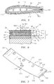
- FIG. 1 shows a coated part 20 comprising a metallic substrate 22 and a coating system 24 atop a surface 26 of the substrate.
- an initial deposited layer 28 of the coating system 24 is a bond coat.
- An exemplary bond coat is an MCrAlY.
- An alternative bond coat is a diffusion aluminide. With the exemplary coating system, there is a partial diffusion of the bond coat with the substrate in a diffusion zone 30.
- a ceramic TBC is then applied.
- An exemplary application comprises a base layer 32 and an additional layer 34 outboard thereof.
- FIG. 1 also shows a TGO layer 38 which, optionally, may grow on the bondcoat.
- the layer 34 is an outboardmost layer whose outer/outboard/exterior surface 40 forms the outer/outboard/exterior surface of the coating system and coated article as a whole.
- the outer layer 34 and/or any additional outboardmost layer may be adapted to provide resistance to CMAS infiltration.
- the layer 32 and 34 are of like composition to each other (e.g., of exactly the same composition or within standard industry specifications for a given single coating).
- An exemplary composition is a 7YSZ.
- Exemplary application techniques for the layers 32 and 34 include physical vapour deposition (e.g., electron beam physical vapour deposition (EB-PVD) or ion enhanced electron beam physical deposition (IE-EB-PVD)).
- FIG. 1 shows a local average surface normal 500 for the surface 40. This is effectively coincident with local average surface normals for the surfaces of each of the layers of the coating system and the substrate surface 26. The average is used because local angles may vary due to roughness.
- the exemplary layers 32 and 34 have columnar microstructure with respective column interfaces/boundaries schematically shown as 50 and 52. These are generally coincident with the growth directions of the coatings. The boundaries may be associated with pores. The transverse pore dimensions may be relatively large near the bondcoat and at the exposed outer surface of any layer.
- the exemplary boundaries 50 are approximately normal to the surface (e.g., parallel to the direction 500). This may be achieved by orienting the substrate essentially normal to the vapour flowpath from the vapour source during deposition.
- the exemplary boundaries 52 are, however, off normal: extending in a direction 502 off parallel to 500 by an angle ⁇ 1 .
- FIG. 1 also shows a local direction 510 of the gas flow over the surface 40.
- An angle ⁇ 2 is between the direction 502 and the direction 510.
- FIG. 2 is a plan view of the part showing a projection 502' of the boundary direction 502 and showing the local flow direction 510.
- An angle ⁇ 3 is between the projection 502' and the direction 510.
- the boundary direction of the layer 34 may be selected to largely minimize ingestion of CMAS into the interfaces/boundaries 52. This may be achieved by orienting the openings of the boundaries at the surface 40 to face away from the flow. For example, this may orient the direction 502 closer to the local downstream direction defined by the direction 510 rather than to the opposite upstream direction. Thus, the angle ⁇ 1 may be selected to be sufficiently large while the angle ⁇ 3 may be selected to be sufficiently small. Subject to various deposition constraints, it may be sought to bring the direction 502 as close as possible to parallel with the direction 510. To the extent that the distribution of the direction 510 varies across the surface of the part, the distribution of the direction 502 may similarly be varied.
- the part may be progressively reoriented to provide the desired distribution of the direction 502.
- an actuator such as a 6-axis industrial robot may manipulate the part/substrate during deposition.
- the layers 32 and 34 may be formed as during a continuous process (e.g., a continuous IE-EB-PVD process) merely changing the part orientation (or movement path) at the appropriate time to transition or there may be a stoppage or other change between stages of deposition.
- Ion enhancement reduces intra-columnar TBC porosity and heightens the coating stoichiometry due to higher energies of adatoms (ions) on the coating surface during deposition.
- RF power is applied to the inductor; while the bias voltage to the sample is applied from a pulse modulator using a contact device.
- Exemplary bias voltage is 1.0 - 2.0 kV
- duty cycle is in a range of 0.1 - 0.7
- pulse frequency is about 2 kHz.
- FIG. 1 shows an exemplary overall coating thickness T (not including the diffusion layer 30).
- T the exemplary bond coat thicknesses is shown as T 1 .
- Exemplary thickness of the layer 32 is T 2 and of layer 34 is T 3 for a combined TBC thickness T 4 .
- Exemplary TGO thickness T 5 may, as the TGO grows, reduce bond coat thicknesses T 1 .
- An exemplary angle ⁇ 1 is 30 - 60°, more narrowly, 35 - 55° or 40 - 50° with a nominal 45° value. This may be along a majority of any relevant region. Part shape and plume access may restrict ability to obtain uniformity or other desired distribution.
- One of the countervailing factors or constraints alluded to above is that higher deposition angles (higher ⁇ ) have been identified as leading to higher porosity thereby substantially countering advantages against infiltration. The relationship between angle and porosity is generally discussed in S. Gu et al., "Thermal Conductivity of Zirconia Coatings with Zig-Zag Pore Microstructures", Acta Mater., 49, 2001, pp. 2539-2547 and D.D.
- An exemplary angle ⁇ 3 is less than 90° along any important regions of the part, more narrowly, less than 45° along a majority of any important area (e.g., the surface of an airfoil or the hot surface of a combustor panel), more narrowly, less than 30° or less than 20°.
- Exemplary T is 300 - 1000 ⁇ m, more narrowly, 500 - 700 ⁇ m.
- Exemplary T 2 is 200 - 1000 ⁇ m, more narrowly, 300 - 500 ⁇ m.
- Exemplary T 3 is at least 5 ⁇ m, more narrowly, 5 - 200 ⁇ m, or 10 - 50 ⁇ m.
- An exemplary ratio of T 2 to T 3 is 1:1 - 5:1, more narrowly, 2:1 - 3:1.
- FIG. 3 shows a blade 100 having an airfoil 102 extending from a proximal end at a platform 104 to a distal end or tip 106.
- the platform has an outboard (gas path facing surface 110).
- An attachment root 108 depends from the underside of the platform 104.
- FIG. 4 shows a vane 120 having an airfoil 122 extending from an inboard end at an inboard platform or shroud 124 to an outboard end at an outboard platform or shroud 126.
- the inboard platform 124 has an outer surface (gas path facing surface) 128 while the shroud 126 has an inboard surface (gas path facing surface) 130.
- FIG. 5 shows the airfoil of either the blade or vane.
- the airfoil has a leading edge 140 and a trailing edge 142.
- the airfoil has a suction side or surface 144 and a pressure side or surface 146.
- the direction 510 is the local streamwise direction which, along each side extends from the leading edge toward the trailing edge.
- FIG. 5 also schematically shows boundary directions of the two TBC layers (thickness exaggerated). The respective directions 502 are selected to provide the desired relationship to the directions 510 discussed above.
- the substrate may be a substrate of a combustor panel (e.g., a floatwall panel).
- a combustor panel e.g., a floatwall panel
- An exemplary floatwall panel has a gas path facing surface formed as a frustoconical segment.
- An exemplary combustor is formed by a number of concentric inner rings and outer rings of such panels.
- the flow direction 510 along each such panel may be generally from an upstream edge to a downstream edge.
- the boundary angle may be oriented accordingly with similar relationships to those described above.
- FIG. 7 shows a turbine engine combustor panel 220 which may be formed having a body 221 shaped as a generally frustoconical segment having inboard and outboard surfaces 222 and 224.
- the exemplary panel is configured for use in an annular combustor circumscribing the engine centreline.
- the inboard surface 222 forms an interior surface (i.e., facing the combustor interior) so that the panel is an outboard panel.
- the inboard surface would be the exterior surface.
- mounting features such as studs 226 extend from the outboard surface for securing the panel relative to the engine.
- the exemplary panel further includes an upstream/leading edge 228, a downstream/trailing edge 230 and lateral edges 232 and 234.
- the panel may include rails or standoffs 236 extending from the exterior surface 224 for engaging a combustor shell (not shown).
- the exemplary panel includes a circumferential array of large apertures for the introduction of process air. Smaller apertures (not shown) may be provided for film cooling.
- select panels may accommodate other openings for spark plug or igniter placement.
- the outer layer may be formed by a modified process.
- One modified process involves applying the outer layer via ion enhanced electron beam physical vapour deposition (IE-EB-PVD) whereas the layer 32 may be applied via mere EB-PVD.
- the inner layer 32 may be deposited optionally by standard EB-PVD or ion enhanced EB-PVD technique, while ion enhancement application may be preferred during the whole process of forming the outer layer 34 in order to reduce excessive porosity appearing due to inclined deposition.
- a first post deposition treatment involves a mechanical smoothing (e.g., burnishing or machining) to reduce roughness. By reducing roughness, the chances of trapping contaminants is reduced. Also, wettability by molten CMAS may be reduced by the associated smoothing.
- An exemplary burnishing involves diamond, roller burnishing, and the like.
- An exemplary machining involves mechanical grinding/polishing with media such as grinding paper, diamond paste, Al and Cr oxides, and the like. As applied coating thickness may be sufficient to leave post-smoothing T 3 in the ranges noted above.
- FIG. 6 shows a coated part 20' comprising a metallic substrate 22 and a coating system 24' atop a surface 26 of the substrate. Otherwise similar to the part 20, and system 24, FIG. 6 shows a remelt zone/layer 42 as an outboardmost layer whose outer/outboard/exterior surface 44 forms the outer/outboard/exterior surface of the coated article as a whole.
- an energy source e.g., ion beam, electron beam, or laser beam
- An exemplary remelting involves leaving a remelt depth T 6 of 2 -20 ⁇ m, more narrowly, about 3 - 8 ⁇ m or 5 ⁇ m. This leaves the layer 34 with a thickness T 3 ' which may be the same as T 3 post machining from the prior embodiment.
- the remelt may further increase generic erosion resistance by hardening and smoothing. Remelt can obliterate the separation between columns, at least partially, so as to make molten CMAS infiltration between the columns more difficult. Remelting is expected also to considerably increase hardness of the surface layer, and so to improve TBC erosion resistance
- Milling/machining is used with the goal of smoothing the TBC surface, so the thickness of removed ceramic depends on the as-deposited surface roughness.
- Remelted layer thickness is dictated, on the one hand, to be sufficiently thick to provide effect (e.g., several micrometers at least); and, on the other hand, to be sufficiently thin to avoid a noticeable deterioration in thermal stress relaxation performance of EB-PVD ceramics (e.g., not thicker than 25 - 30 ⁇ m to avoid undesirably reducing tolerance to thermal stresses).
- a manufacturing process for the part may involve determining or receiving a part configuration. For example a solid model data file for an existing part may be received.
- the gas flow direction distribution may be determined or received (e.g., via experimental flow measurement, via observation of wear on an existing part, and/or via computational fluid/combustion dynamics modelling). From the shape and the gas flow direction distribution, an application process associated with the column boundary directions may be determined. This may be experimentally determined to best approach alignment with the flow directions in view of any limitations associated with the deposition equipment to be used and/or part geometry.
- the coating may be applied to provide the column boundary direction distribution.
Landscapes
- Chemical & Material Sciences (AREA)
- Engineering & Computer Science (AREA)
- Inorganic Chemistry (AREA)
- Chemical Kinetics & Catalysis (AREA)
- Materials Engineering (AREA)
- Mechanical Engineering (AREA)
- Metallurgy (AREA)
- Organic Chemistry (AREA)
- Ceramic Engineering (AREA)
- Turbine Rotor Nozzle Sealing (AREA)
Abstract
A coated part is exposed to a gas flow. The gas flow has a characteristic gas flow direction distribution over a surface of the coated part. The coated part has a substrate (22) having a substrate surface (26) and a coating (24) over the substrate surface. The coating comprises (24) at least one coating layer. A first such layer (34) is columnar and has a column boundary direction (502) distribution. The column boundary direction distribution is selected for partial local alignment with the gas flow direction (510) distribution.
Description
- The disclosure relates to gas turbine engines. More particularly, the disclosure relates to thermal barrier coating systems.
- Gas turbine engine combustor and turbine components are exposed to extreme heat during engine operation. They are also exposed to the mechanical action of the gas flow and to chemical reaction from combustion gas and entrained matter. Exemplary such hot section components include combustor panels, vanes, blades, air seals, and the like. Accordingly, it is customary to coat such components with thermal barrier coating (TBC) systems.
- Exemplary thermal barrier coating systems include two layer thermal barrier coating systems. An exemplary system includes a MCrAlY bond coat (where M identifies one or more of Fe, Ni, and Co) and a yttria-stabilized zirconia (YSZ) thermal barrier coat (TBC). While barrier coat layer is being deposited or during an initial heating cycle, a thermally grown oxide (TGO) layer (e.g., alumina) forms atop the bond coat layer. As time-at-temperature and the number of cycles increase, this TGO interface layer grows in thickness.
US Pat. Nos. 4,405,659 and6,060,177 disclose exemplary systems. - Especially when used in sandy desert environments, engine components are subject to a particular form of fouling/damage known as molten sand attack or CMAS. CMAS is an abbreviation for "calcium-magnesium-aluminium-silicon (silicate)". Specific CMAS oxides include CaO, MgO, Al2O3, and SiO2. CMAS components may form a eutectic with a relatively low melting point (e.g., approximately 1240 °C). The molten CMAS material infiltrates into porous coatings (e.g., between the columns of columnar ceramic). This can alter the chemical composition of the coating and/or cause structural failure of the coating. Efforts to address CMAS have centred on improved barrier coatings. For example,
US patents 5,660,885 ,5,871,820 ,5,914,189 ,6,720,038 ,6,627,323 ,6,465,090 , all reference coatings relative to CMAS. - One aspect of the disclosure involves a coated part for exposure to a gas flow. The gas flow has a characteristic gas flow direction distribution over a surface of the coated part. The coated part has a substrate having a substrate surface and a coating over the substrate surface. The coating comprises at least one coating layer. A first such layer is columnar and has a column boundary direction distribution. The column boundary direction distribution is selected for partial local alignment with the gas flow direction distribution.
- The part may be manufactured by: determining or receiving a part configuration; determining or receiving the gas flow direction distribution; from the shape and the gas flow direction distribution, determining an application process associated with the column boundary directions; and applying the coating to provide the column boundary direction distribution. The applying of the coating may comprise applying the layer via a PVD, EB-PVD, or IE-EB-PVD process.
- The details of one or more embodiments are set forth in the accompanying drawings and the description below. Other features, objects, and advantages will be apparent from the description and drawings, and from the claims.
-
-
FIG. 1 is a schematic sectional view of a coating system on a substrate. -
FIG. 2 is a schematic plan/projected view of the surface of the coating system. -
FIG. 3 is a simplified view of a blade. -
FIG. 4 is a simplified view of a vane. -
FIG. 5 is a simplified cross sectional view of an airfoil of a blade or vane. -
FIG. 6 is a schematic sectional view of a second coating system on a substrate. -
FIG. 7 is a simplified view of a combustor panel. - Like reference numbers and designations in the various drawings indicate like elements.
-
FIG. 1 shows a coatedpart 20 comprising ametallic substrate 22 and acoating system 24 atop asurface 26 of the substrate. After any surface preparation of the substrate, an initial depositedlayer 28 of thecoating system 24 is a bond coat. An exemplary bond coat is an MCrAlY. An alternative bond coat is a diffusion aluminide. With the exemplary coating system, there is a partial diffusion of the bond coat with the substrate in adiffusion zone 30. - After depositing the bond coat, a ceramic TBC is then applied. An exemplary application comprises a
base layer 32 and anadditional layer 34 outboard thereof.FIG. 1 also shows aTGO layer 38 which, optionally, may grow on the bondcoat. In a first exemplary situation, thelayer 34 is an outboardmost layer whose outer/outboard/exterior surface 40 forms the outer/outboard/exterior surface of the coating system and coated article as a whole. As is discussed further below, theouter layer 34 and/or any additional outboardmost layer may be adapted to provide resistance to CMAS infiltration. - In a first exemplary implementation of the
coating system 24, thelayer - Exemplary application techniques for the
layers FIG. 1 shows a local average surface normal 500 for thesurface 40. This is effectively coincident with local average surface normals for the surfaces of each of the layers of the coating system and thesubstrate surface 26. The average is used because local angles may vary due to roughness. Theexemplary layers exemplary boundaries 50 are approximately normal to the surface (e.g., parallel to the direction 500). This may be achieved by orienting the substrate essentially normal to the vapour flowpath from the vapour source during deposition. Theexemplary boundaries 52 are, however, off normal: extending in adirection 502 off parallel to 500 by an angle θ1.FIG. 1 also shows alocal direction 510 of the gas flow over thesurface 40. An angle θ2 is between thedirection 502 and thedirection 510. -
FIG. 2 is a plan view of the part showing a projection 502' of theboundary direction 502 and showing thelocal flow direction 510. An angle θ3 is between the projection 502' and thedirection 510. - In order to limit infiltration into the TBC of contaminants in the gas flow, the boundary direction of the
layer 34 may be selected to largely minimize ingestion of CMAS into the interfaces/boundaries 52. This may be achieved by orienting the openings of the boundaries at thesurface 40 to face away from the flow. For example, this may orient thedirection 502 closer to the local downstream direction defined by thedirection 510 rather than to the opposite upstream direction. Thus, the angle θ1 may be selected to be sufficiently large while the angle θ3 may be selected to be sufficiently small. Subject to various deposition constraints, it may be sought to bring thedirection 502 as close as possible to parallel with thedirection 510. To the extent that the distribution of thedirection 510 varies across the surface of the part, the distribution of thedirection 502 may similarly be varied. This may be achieved by orienting the part during deposition so that thedirection 502 is anti-parallel to the direction of flow from the deposition source. During deposition, the part may be progressively reoriented to provide the desired distribution of thedirection 502. For example, if the vapour source is non-moving, an actuator such as a 6-axis industrial robot may manipulate the part/substrate during deposition. - The
layers -
FIG. 1 shows an exemplary overall coating thickness T (not including the diffusion layer 30). Of T, the exemplary bond coat thicknesses is shown as T1. Exemplary thickness of thelayer 32 is T2 and oflayer 34 is T3 for a combined TBC thickness T4. Exemplary TGO thickness T5 may, as the TGO grows, reduce bond coat thicknesses T1. - An exemplary angle θ1 is 30 - 60°, more narrowly, 35 - 55° or 40 - 50° with a nominal 45° value. This may be along a majority of any relevant region. Part shape and plume access may restrict ability to obtain uniformity or other desired distribution. One of the countervailing factors or constraints alluded to above is that higher deposition angles (higher θ) have been identified as leading to higher porosity thereby substantially countering advantages against infiltration. The relationship between angle and porosity is generally discussed in S. Gu et al., "Thermal Conductivity of Zirconia Coatings with Zig-Zag Pore Microstructures", Acta Mater., 49, 2001, pp. 2539-2547 and D.D. Hass et al., "Low Thermal Conductivity Vapour Deposited Zirconia Microstructures", Acta Mater., 49, 2001, pp. 973-983. An exemplary angle θ3 is less than 90° along any important regions of the part, more narrowly, less than 45° along a majority of any important area (e.g., the surface of an airfoil or the hot surface of a combustor panel), more narrowly, less than 30° or less than 20°.
- Exemplary T is 300 - 1000 µm, more narrowly, 500 - 700 µm. Exemplary T2 is 200 - 1000 µm, more narrowly, 300 - 500 µm. Exemplary T3 is at least 5 µm, more narrowly, 5 - 200 µm, or 10 - 50 µm. An exemplary ratio of T2 to T3 is 1:1 - 5:1, more narrowly, 2:1 - 3:1.
- A first example of a situation where this may be put into practice is of a part having an airfoil (e.g., a blade or vane of a turbine section).
FIG. 3 shows ablade 100 having anairfoil 102 extending from a proximal end at aplatform 104 to a distal end ortip 106. The platform has an outboard (gas path facing surface 110). Anattachment root 108 depends from the underside of theplatform 104. -
FIG. 4 shows avane 120 having anairfoil 122 extending from an inboard end at an inboard platform orshroud 124 to an outboard end at an outboard platform orshroud 126. Theinboard platform 124 has an outer surface (gas path facing surface) 128 while theshroud 126 has an inboard surface (gas path facing surface) 130. -
FIG. 5 shows the airfoil of either the blade or vane. The airfoil has aleading edge 140 and a trailingedge 142. The airfoil has a suction side orsurface 144 and a pressure side orsurface 146. Along the airflow, thedirection 510 is the local streamwise direction which, along each side extends from the leading edge toward the trailing edge.FIG. 5 also schematically shows boundary directions of the two TBC layers (thickness exaggerated). Therespective directions 502 are selected to provide the desired relationship to thedirections 510 discussed above. - Among other part/component variations, the substrate may be a substrate of a combustor panel (e.g., a floatwall panel). An exemplary floatwall panel has a gas path facing surface formed as a frustoconical segment. An exemplary combustor is formed by a number of concentric inner rings and outer rings of such panels. The
flow direction 510 along each such panel may be generally from an upstream edge to a downstream edge. The boundary angle may be oriented accordingly with similar relationships to those described above.FIG. 7 shows a turbineengine combustor panel 220 which may be formed having abody 221 shaped as a generally frustoconical segment having inboard andoutboard surfaces inboard surface 222 forms an interior surface (i.e., facing the combustor interior) so that the panel is an outboard panel. For an inboard panel, the inboard surface would be the exterior surface. Accordingly, mounting features such asstuds 226 extend from the outboard surface for securing the panel relative to the engine. The exemplary panel further includes an upstream/leadingedge 228, a downstream/trailingedge 230 andlateral edges standoffs 236 extending from theexterior surface 224 for engaging a combustor shell (not shown). The exemplary panel includes a circumferential array of large apertures for the introduction of process air. Smaller apertures (not shown) may be provided for film cooling. Moreover, select panels may accommodate other openings for spark plug or igniter placement. - Among further process/composition variations, the outer layer may be formed by a modified process. One modified process involves applying the outer layer via ion enhanced electron beam physical vapour deposition (IE-EB-PVD) whereas the
layer 32 may be applied via mere EB-PVD. For example, theinner layer 32 may be deposited optionally by standard EB-PVD or ion enhanced EB-PVD technique, while ion enhancement application may be preferred during the whole process of forming theouter layer 34 in order to reduce excessive porosity appearing due to inclined deposition. - Additional variations involve post deposition treatment. A first post deposition treatment involves a mechanical smoothing (e.g., burnishing or machining) to reduce roughness. By reducing roughness, the chances of trapping contaminants is reduced. Also, wettability by molten CMAS may be reduced by the associated smoothing. An exemplary burnishing involves diamond, roller burnishing, and the like. An exemplary machining involves mechanical grinding/polishing with media such as grinding paper, diamond paste, Al and Cr oxides, and the like. As applied coating thickness may be sufficient to leave post-smoothing T3 in the ranges noted above.
- Another surface treatment involves a post deposition rastering with an energy source (e.g., ion beam, electron beam, or laser beam) to achieve a degree of melting or remelting to smooth and seal the exposed surface.
FIG. 6 shows a coated part 20' comprising ametallic substrate 22 and a coating system 24' atop asurface 26 of the substrate. Otherwise similar to thepart 20, andsystem 24,FIG. 6 shows a remelt zone/layer 42 as an outboardmost layer whose outer/outboard/exterior surface 44 forms the outer/outboard/exterior surface of the coated article as a whole. - An exemplary remelting involves leaving a remelt depth T6 of 2 -20 µm, more narrowly, about 3 - 8 µm or 5 µm. This leaves the
layer 34 with a thickness T3' which may be the same as T3 post machining from the prior embodiment. In addition to increasing resistance to the chemical and mechanical working (expansion and/or contraction) components of CMAS attack, the remelt may further increase generic erosion resistance by hardening and smoothing. Remelt can obliterate the separation between columns, at least partially, so as to make molten CMAS infiltration between the columns more difficult. Remelting is expected also to considerably increase hardness of the surface layer, and so to improve TBC erosion resistance - Milling/machining (grinding, polishing) is used with the goal of smoothing the TBC surface, so the thickness of removed ceramic depends on the as-deposited surface roughness. Remelted layer thickness is dictated, on the one hand, to be sufficiently thick to provide effect (e.g., several micrometers at least); and, on the other hand, to be sufficiently thin to avoid a noticeable deterioration in thermal stress relaxation performance of EB-PVD ceramics (e.g., not thicker than 25 - 30 µm to avoid undesirably reducing tolerance to thermal stresses).
- A manufacturing process for the part may involve determining or receiving a part configuration. For example a solid model data file for an existing part may be received. The gas flow direction distribution may be determined or received (e.g., via experimental flow measurement, via observation of wear on an existing part, and/or via computational fluid/combustion dynamics modelling). From the shape and the gas flow direction distribution, an application process associated with the column boundary directions may be determined. This may be experimentally determined to best approach alignment with the flow directions in view of any limitations associated with the deposition equipment to be used and/or part geometry. The coating may be applied to provide the column boundary direction distribution.
- Although an embodiment is described above in detail, such description is not intended for limiting the scope of the present disclosure. It will be understood that various modifications may be made without departing from the spirit and scope of the disclosure. For example, when modifying a baseline part and/or baseline coating system, details of the existing part and system may influence details of any particular implementation. Accordingly, other embodiments are within the scope of the following claims.
Claims (14)
- A coated part for exposure to a gas flow having a characteristic gas flow direction (510) distribution over a surface of the coated part, the coated part comprising:a substrate (22) having a substrate surface (26); anda coating (24) over the surface and comprising at least one coating layer, a first said layer (34) being columnar and having a column boundary direction (502) distribution, the column boundary direction distribution selected for partial local alignment with the gas flow direction distribution.
- The part of claim 1 including:an airfoil portion having a leading edge (140), a trailing edge (142), a pressure side (144) and a suction side (146);along the respective pressure side and suction side, respective streamwise directions extend from the leading edge toward the trailing edge; andthe column boundary direction is at least partially aligned (θ3 is less than 90°) with the streamwise direction on majorities of both said pressure side and said suction side.
- The part of claim 2 wherein:said alignment along said majorities is within 45°.
- The part of claim 1, being a combustor panel (220) in an annular combustor of a gas turbine engine and wherein, along a majority of a hot side of the panel the columnar direction distribution is more than 30° off normal and, in projection, within 30° of downstream.
- The part of any preceding claim wherein:along at least a portion of the part, the first layer (34) has a thickness (T3) of 10 - 50 µm.
- The part of any preceding claim wherein:along at least a portion of the part, the first layer (34) comprises at least 10% of a local total coating thickness (T).
- The part of any preceding claim wherein:along at least a portion of the part, the first layer (34) forms a majority of a local total coating thickness (T).
- The part of any preceding claim wherein:the first layer (34) comprises a YSZ.
- The part of any preceding claim wherein:the first layer (34) is atop a second layer (32) of like composition but less aligned with the flow direction distribution.
- The part of claim 9 wherein:along at least a portion of the part, a combined thickness (T4) of the first layer (34) and second layer (32) is at least 75% of a total coating thickness (T).
- The part of any preceding claim wherein:along at least a portion of the part, the first layer (34) is an outermost layer.
- The part of any of claims 1 to 10, wherein the coating further comprises:an additional layer (42) atop the first layer (34) and characterized by at least one of:a remelted microstructure; anda milled microstructure.
- A method for manufacturing the part of claim 1 comprising:determining or receiving a part configuration;determining or receiving the gas flow direction distribution;from the shape and the gas flow direction distribution, determining an application process associated with the column boundary directions; andapplying the coating to provide the column boundary direction distribution.
- The method of claim 13 wherein:the applying of the coating comprises applying the layer via a PVD, EB-PVD, or IE-EB-PVD process.
Applications Claiming Priority (1)
| Application Number | Priority Date | Filing Date | Title |
|---|---|---|---|
| US12/981,661 US9139897B2 (en) | 2010-12-30 | 2010-12-30 | Thermal barrier coatings and methods of application |
Publications (1)
| Publication Number | Publication Date |
|---|---|
| EP2471975A1 true EP2471975A1 (en) | 2012-07-04 |
Family
ID=45444466
Family Applications (1)
| Application Number | Title | Priority Date | Filing Date |
|---|---|---|---|
| EP20110195328 Withdrawn EP2471975A1 (en) | 2010-12-30 | 2011-12-22 | Thermal barrier coatings and method of application |
Country Status (2)
| Country | Link |
|---|---|
| US (1) | US9139897B2 (en) |
| EP (1) | EP2471975A1 (en) |
Cited By (1)
| Publication number | Priority date | Publication date | Assignee | Title |
|---|---|---|---|---|
| US10995624B2 (en) | 2016-08-01 | 2021-05-04 | General Electric Company | Article for high temperature service |
Families Citing this family (10)
| Publication number | Priority date | Publication date | Assignee | Title |
|---|---|---|---|---|
| DE102011007224A1 (en) * | 2011-04-12 | 2012-10-18 | Rolls-Royce Deutschland Ltd & Co Kg | Method and production of a one-piece rotor section and one-piece rotor section |
| DE102012018604A1 (en) | 2012-09-20 | 2014-03-20 | Rolls-Royce Deutschland Ltd & Co Kg | Rolling tool device |
| DE102012018605A1 (en) | 2012-09-20 | 2014-03-20 | Rolls-Royce Deutschland Ltd & Co Kg | Rolling tool device |
| US20140083115A1 (en) * | 2012-09-27 | 2014-03-27 | United Technologies Corporation | Article with dielectric mirror coating system |
| US20160254125A1 (en) * | 2015-02-27 | 2016-09-01 | Lam Research Corporation | Method for coating surfaces |
| FR3038624B1 (en) * | 2015-07-08 | 2019-10-25 | Safran Aircraft Engines | PROTECTIVE COATING FORMING A THERMAL BARRIER, SUBSTRATE COVERED WITH SUCH COATING, AND GAS TURBINE PART COMPRISING SUCH A SUBSTRATE |
| JP6908973B2 (en) * | 2016-06-08 | 2021-07-28 | 三菱重工業株式会社 | Manufacturing methods for thermal barrier coatings, turbine components, gas turbines, and thermal barrier coatings |
| US10465607B2 (en) | 2017-04-05 | 2019-11-05 | United Technologies Corporation | Method of manufacturing conductive film holes |
| US20190106780A1 (en) | 2017-10-11 | 2019-04-11 | United Technologies Corporation | Methods for Applying Thermal Barrier Coatings |
| GB202207827D0 (en) * | 2022-05-27 | 2022-07-13 | Rolls Royce Plc | Method of forming protective coating and coated article comprising protective coating |
Citations (12)
| Publication number | Priority date | Publication date | Assignee | Title |
|---|---|---|---|---|
| US4405659A (en) | 1980-01-07 | 1983-09-20 | United Technologies Corporation | Method for producing columnar grain ceramic thermal barrier coatings |
| US5660885A (en) | 1995-04-03 | 1997-08-26 | General Electric Company | Protection of thermal barrier coating by a sacrificial surface coating |
| US5871820A (en) | 1995-04-06 | 1999-02-16 | General Electric Company | Protection of thermal barrier coating with an impermeable barrier coating |
| US5876860A (en) * | 1997-12-09 | 1999-03-02 | N.V. Interturbine | Thermal barrier coating ceramic structure |
| US5914189A (en) | 1995-06-26 | 1999-06-22 | General Electric Company | Protected thermal barrier coating composite with multiple coatings |
| EP0940480A1 (en) * | 1998-01-13 | 1999-09-08 | ROLLS-ROYCE plc | A metallic article having a thermal barrier coating and a method of application thereof |
| US6060177A (en) | 1998-02-19 | 2000-05-09 | United Technologies Corporation | Method of applying an overcoat to a thermal barrier coating and coated article |
| US6465090B1 (en) | 1995-11-30 | 2002-10-15 | General Electric Company | Protective coating for thermal barrier coatings and coating method therefor |
| US6627323B2 (en) | 2002-02-19 | 2003-09-30 | General Electric Company | Thermal barrier coating resistant to deposits and coating method therefor |
| US6720038B2 (en) | 2002-02-11 | 2004-04-13 | General Electric Company | Method of forming a coating resistant to deposits and coating formed thereby |
| EP1640473A1 (en) * | 2004-09-14 | 2006-03-29 | General Electric Company | Thermal barrier coating with modulated grain structure and method therefor |
| US20080317998A1 (en) * | 2006-01-13 | 2008-12-25 | Wolfgang Eichmann | Wear-resistant coating |
Family Cites Families (15)
| Publication number | Priority date | Publication date | Assignee | Title |
|---|---|---|---|---|
| US6471881B1 (en) * | 1999-11-23 | 2002-10-29 | United Technologies Corporation | Thermal barrier coating having improved durability and method of providing the coating |
| US6703137B2 (en) * | 2001-08-02 | 2004-03-09 | Siemens Westinghouse Power Corporation | Segmented thermal barrier coating and method of manufacturing the same |
| US7226668B2 (en) | 2002-12-12 | 2007-06-05 | General Electric Company | Thermal barrier coating containing reactive protective materials and method for preparing same |
| US7326470B2 (en) * | 2004-04-28 | 2008-02-05 | United Technologies Corporation | Thin 7YSZ, interfacial layer as cyclic durability (spallation) life enhancement for low conductivity TBCs |
| US20060016191A1 (en) * | 2004-07-23 | 2006-01-26 | Honeywell International Inc. | Combined effusion and thick TBC cooling method |
| US7416788B2 (en) | 2005-06-30 | 2008-08-26 | Honeywell International Inc. | Thermal barrier coating resistant to penetration by environmental contaminants |
| US20070116883A1 (en) | 2005-11-22 | 2007-05-24 | General Electric Company | Process for forming thermal barrier coating resistant to infiltration |
| US7785722B2 (en) | 2006-01-20 | 2010-08-31 | United Technologies Corporation | CMAS resistant thermal barrier coating |
| EP1942250A1 (en) * | 2007-01-05 | 2008-07-09 | Siemens Aktiengesellschaft | Component with bevelled grooves in the surface and method for operating a turbine |
| US7833586B2 (en) | 2007-10-24 | 2010-11-16 | General Electric Company | Alumina-based protective coatings for thermal barrier coatings |
| US8062759B2 (en) | 2007-12-27 | 2011-11-22 | General Electric Company | Thermal barrier coating systems including a rare earth aluminate layer for improved resistance to CMAS infiltration and coated articles |
| US20090169752A1 (en) | 2007-12-27 | 2009-07-02 | Ming Fu | Method for Improving Resistance to CMAS Infiltration |
| US20090186237A1 (en) | 2008-01-18 | 2009-07-23 | Rolls-Royce Corp. | CMAS-Resistant Thermal Barrier Coatings |
| EP2128299B1 (en) | 2008-05-29 | 2016-12-28 | General Electric Technology GmbH | Multilayer thermal barrier coating |
| US20110052406A1 (en) * | 2009-08-25 | 2011-03-03 | General Electric Company | Airfoil and process for depositing an erosion-resistant coating on the airfoil |
-
2010
- 2010-12-30 US US12/981,661 patent/US9139897B2/en active Active
-
2011
- 2011-12-22 EP EP20110195328 patent/EP2471975A1/en not_active Withdrawn
Patent Citations (12)
| Publication number | Priority date | Publication date | Assignee | Title |
|---|---|---|---|---|
| US4405659A (en) | 1980-01-07 | 1983-09-20 | United Technologies Corporation | Method for producing columnar grain ceramic thermal barrier coatings |
| US5660885A (en) | 1995-04-03 | 1997-08-26 | General Electric Company | Protection of thermal barrier coating by a sacrificial surface coating |
| US5871820A (en) | 1995-04-06 | 1999-02-16 | General Electric Company | Protection of thermal barrier coating with an impermeable barrier coating |
| US5914189A (en) | 1995-06-26 | 1999-06-22 | General Electric Company | Protected thermal barrier coating composite with multiple coatings |
| US6465090B1 (en) | 1995-11-30 | 2002-10-15 | General Electric Company | Protective coating for thermal barrier coatings and coating method therefor |
| US5876860A (en) * | 1997-12-09 | 1999-03-02 | N.V. Interturbine | Thermal barrier coating ceramic structure |
| EP0940480A1 (en) * | 1998-01-13 | 1999-09-08 | ROLLS-ROYCE plc | A metallic article having a thermal barrier coating and a method of application thereof |
| US6060177A (en) | 1998-02-19 | 2000-05-09 | United Technologies Corporation | Method of applying an overcoat to a thermal barrier coating and coated article |
| US6720038B2 (en) | 2002-02-11 | 2004-04-13 | General Electric Company | Method of forming a coating resistant to deposits and coating formed thereby |
| US6627323B2 (en) | 2002-02-19 | 2003-09-30 | General Electric Company | Thermal barrier coating resistant to deposits and coating method therefor |
| EP1640473A1 (en) * | 2004-09-14 | 2006-03-29 | General Electric Company | Thermal barrier coating with modulated grain structure and method therefor |
| US20080317998A1 (en) * | 2006-01-13 | 2008-12-25 | Wolfgang Eichmann | Wear-resistant coating |
Non-Patent Citations (2)
| Title |
|---|
| D.D. HASS ET AL.: "Low Thermal Conductivity Vapour Deposited Zirconia Microstructures", ACTA MATER., vol. 49, 2001, pages 973 - 983, XP002987270, DOI: doi:10.1016/S1359-6454(00)00403-1 |
| S. GU ET AL.: "Thermal Conductivity of Zirconia Coatings with Zig-Zag Pore Microstructures", ACTA MATER., vol. 49, 2001, pages 2539 - 2547, XP001074772, DOI: doi:10.1016/S1359-6454(01)00141-0 |
Cited By (1)
| Publication number | Priority date | Publication date | Assignee | Title |
|---|---|---|---|---|
| US10995624B2 (en) | 2016-08-01 | 2021-05-04 | General Electric Company | Article for high temperature service |
Also Published As
| Publication number | Publication date |
|---|---|
| US20120167573A1 (en) | 2012-07-05 |
| US9139897B2 (en) | 2015-09-22 |
Similar Documents
| Publication | Publication Date | Title |
|---|---|---|
| US9139897B2 (en) | Thermal barrier coatings and methods of application | |
| KR102630007B1 (en) | Turbine gap control coatings and methods | |
| EP2275646B1 (en) | Airfoil tip comprising stress mitigating features | |
| US5876860A (en) | Thermal barrier coating ceramic structure | |
| US10041360B2 (en) | Turbomachine component with an erosion and corrosion resistant coating system and method for manufacturing such a component | |
| JP3434504B2 (en) | Insulation method for metal substrate | |
| EP0808913A1 (en) | Method for repairing a thermal barrier coating | |
| US20110052406A1 (en) | Airfoil and process for depositing an erosion-resistant coating on the airfoil | |
| JP2002522646A (en) | Multi-layer thermal insulation coating system | |
| EP2258889A1 (en) | Thermal barrier coatings and methods | |
| US20160281204A1 (en) | Thermal barrier coating repair | |
| EP1889948A2 (en) | Dual layer ceramic coating | |
| WO2016105327A1 (en) | Method for controlling coating delamination caused when forming cooling holes through thermal barrier coatings | |
| EP1686199B1 (en) | Thermal barrier coating system | |
| US10435776B2 (en) | Fire containment coating system for titanium | |
| US6663983B1 (en) | Thermal barrier coating with improved strength and fracture toughness | |
| US20220349312A1 (en) | Hybrid Thermal Barrier Coating | |
| JP2007239101A (en) | Bond coating method for thermal barrier coating | |
| WO2014126633A2 (en) | Spallation-resistant thermal barrier coating | |
| US20150004308A1 (en) | Method for creating a textured bond coat surface | |
| JP4509085B2 (en) | Coating method and apparatus | |
| RU2263157C1 (en) | Method of making elastically adaptable heat barrier coat |
Legal Events
| Date | Code | Title | Description |
|---|---|---|---|
| AK | Designated contracting states |
Kind code of ref document: A1 Designated state(s): AL AT BE BG CH CY CZ DE DK EE ES FI FR GB GR HR HU IE IS IT LI LT LU LV MC MK MT NL NO PL PT RO RS SE SI SK SM TR |
|
| AX | Request for extension of the european patent |
Extension state: BA ME |
|
| PUAI | Public reference made under article 153(3) epc to a published international application that has entered the european phase |
Free format text: ORIGINAL CODE: 0009012 |
|
| 17P | Request for examination filed |
Effective date: 20121210 |
|
| STAA | Information on the status of an ep patent application or granted ep patent |
Free format text: STATUS: THE APPLICATION IS DEEMED TO BE WITHDRAWN |
|
| 18D | Application deemed to be withdrawn |
Effective date: 20140701 |