EP2471616A1 - Method for machining austenite stainless steel equipment and piping, and nuclear power plant equipment and piping machined by means of said method - Google Patents
Method for machining austenite stainless steel equipment and piping, and nuclear power plant equipment and piping machined by means of said method Download PDFInfo
- Publication number
- EP2471616A1 EP2471616A1 EP10811756A EP10811756A EP2471616A1 EP 2471616 A1 EP2471616 A1 EP 2471616A1 EP 10811756 A EP10811756 A EP 10811756A EP 10811756 A EP10811756 A EP 10811756A EP 2471616 A1 EP2471616 A1 EP 2471616A1
- Authority
- EP
- European Patent Office
- Prior art keywords
- machining
- piping
- cut
- depth
- stainless steel
- Prior art date
- Legal status (The legal status is an assumption and is not a legal conclusion. Google has not performed a legal analysis and makes no representation as to the accuracy of the status listed.)
- Granted
Links
Images




Classifications
-
- B—PERFORMING OPERATIONS; TRANSPORTING
- B23—MACHINE TOOLS; METAL-WORKING NOT OTHERWISE PROVIDED FOR
- B23B—TURNING; BORING
- B23B1/00—Methods for turning or working essentially requiring the use of turning-machines; Use of auxiliary equipment in connection with such methods
-
- B—PERFORMING OPERATIONS; TRANSPORTING
- B23—MACHINE TOOLS; METAL-WORKING NOT OTHERWISE PROVIDED FOR
- B23B—TURNING; BORING
- B23B27/00—Tools for turning or boring machines; Tools of a similar kind in general; Accessories therefor
- B23B27/14—Cutting tools of which the bits or tips or cutting inserts are of special material
- B23B27/141—Specially shaped plate-like cutting inserts, i.e. length greater or equal to width, width greater than or equal to thickness
- B23B27/145—Specially shaped plate-like cutting inserts, i.e. length greater or equal to width, width greater than or equal to thickness characterised by having a special shape
-
- B—PERFORMING OPERATIONS; TRANSPORTING
- B23—MACHINE TOOLS; METAL-WORKING NOT OTHERWISE PROVIDED FOR
- B23B—TURNING; BORING
- B23B2200/00—Details of cutting inserts
- B23B2200/28—Angles
- B23B2200/286—Positive cutting angles
-
- B—PERFORMING OPERATIONS; TRANSPORTING
- B23—MACHINE TOOLS; METAL-WORKING NOT OTHERWISE PROVIDED FOR
- B23B—TURNING; BORING
- B23B2222/00—Materials of tools or workpieces composed of metals, alloys or metal matrices
- B23B2222/80—Stainless steel
Definitions
- the present invention relates to a machining method for austenite stainless steel equipment and piping, and nuclear power plant equipment and piping machined by use of this method.
- Austenite stainless steel is chiefly used as material for equipment and piping or the like in a nuclear power plant. It has been known that, by performing cool machining such as ordinary cutting and grinding, etc. on austenite stainless steel, a hardened layer is formed on a surface thereof (see Patent Literature 1, Patent Literature 2, for example). For example, it is said that, generally in recirculation piping or the like of a boiling-reactor nuclear power plant, if the hardness of this hardened layer becomes 300 HV or more in terms of the Vickers hardness, stress corrosion cracking (SCC) is likely to be caused, and the same thing is considered in equipment and piping of a pressurized-water nuclear plant where water circulates.
- SCC stress corrosion cracking
- a rake angle of a cutting tool is set to be 15° or so at the greatest in the light of edge strength (chipping prevention) of the tool and enhancement of its service life, and even if machining conditions such as a depth of cut and cutting speed are adjusted, a hardened layer exceeding the above mentioned hardness (300 HV in terms of the Vickers hardness) is formed during a machining operation.
- the present invention has an object to provide a machining method for austenite stainless steel equipment and piping, which is capable of suppressing generation of a hardened layer and occurrence of SCC without operating an after treatment, and reducing working hours and cost, as well as to provide nuclear power plant equipment and piping machined by use of this method.
- the present invention employs the following solutions.
- the first aspect of the present invention provides a machining method for austenite stainless steel equipment and piping, which includes a finishing treatment process for performing a machining operation by use of a finishing-cut tool whose rake angle is +29° or more to suppress work hardening of a surface.
- the hardness of a machined surface layer is defined as hardness at a depth of 0.01 mm from the surface. If the rake angle is set to be as great as +29° or more, a shear angle of a chip becomes greater and a thickness of the chip becomes thinner, so that cutting force (cutting resistance) required for the cutting becomes smaller.
- the cutting resistance acting on the austenite stainless steel equipment and piping is reduced, therefore it is understood that the hardening of the surface layer can be suppressed.
- the finishing treatment is carried out by the machining using the finishing-cut tool whose tip end is very sharp, and whose rake angle is +29° or more, it is possible to keep the hardness of the finished surface layer to be less than 300 HV in terms of the Vickers hardness. It is thus possible to suppress occurrence of SCC only by use of the machining, without requiring after treatment such as removal of the hardened layer and/or applying compressive stress, which has conventionally been carried out. Since such after treatment can be eliminated, working hours for the operation and cost therefor can be reduced. In addition, since the hardness of the surface layer is low, even if working such as welding that causes tensile stress is applied after the machining, it is possible to maintain the necessary SCC resistance.
- a depth of finishing cut for the finishing-cut tool is preferably 0.1 mm or more and 0.2 mm or less.
- the depth of finishing cut for the finishing-cut tool is set to be 0.1 mm or more and 0.2 mm or less, and if the above machining condition for the finishing treatment process is applied to the entire process when performing the cutting in a predetermined size, it could be considered that the number of machining operations and working hours increase.
- the machining operation is performed by use of a base-cut tool with the depth of base cut that is a greater depth of cut than that in the machining condition for the finishing treatment process, so that the cutting amount of the finishing treatment process can be set to be smaller. Accordingly, it is possible to enhance efficiency of the entire machining operation. In this case, to make the hardness of the surface layer machined in the base treatment process become not so great enables the tool whose tip end is very sharp and whose rake angle is +29° or more to be applicable.
- the depth of base cut is 1 mm, or less, preferably 0.2 mm, or more and 0.3 mm or less.
- the depth of base cut is preferably set to be 0.2 mm or more and 0.3 mm or less.
- the treatment amount of the base treatment process is 0.5 mm thick or more and 2 mm thick or less, preferably 1 mm thick or so.
- the treatment amount of the machining exceeds the above range, in consideration of the machining efficiency, a rough machining treatment process in which rough machining treatment is carried out before the base treatment process is preferable.
- the second aspect of the present invention provides nuclear power plant equipment and piping machined by use of the machining method for austenite stainless steel equipment and piping according to the first aspect.
- the nuclear power plant equipment and piping is manufactured by use of the machining method for austenite stainless steel equipment and piping that can suppress occurrence of SCC, without requiring after treatment such as removal of the hardened layer and/or applying compressive stress, and even if working such as welding that causes tensile stress is applied after the machining, it is possible to maintain the SCC resistance. Accordingly, it is possible to reduce manufacturing time and cost required for the manufacturing.
- the finishing treatment is carried out by the machining using the finishing-cut tool whose rake angle of +29° or more, it is possible to keep the hardness of the machined surface layer to be less than 300 HV in terms of the Vickers hardness. Therefore, it is possible to suppress occurrence of SCC only by use of the machining, without requiring after treatment such as removal of the hardened layer and/or applying compressive stress, or the like, which has conventionally been carried out. Since such after treatment can be eliminated, the working hours and cost can be reduced. In addition, since the hardness of the surface layer is low, even if working such as welding that causes tensile stress is applied after the machining, it is possible to maintain the necessary SCC resistance.
- Fig. 1 illustrates a content of a thinning process for ordinary piping in a pressurized-water nuclear plant utilizing a machining method for austenite stainless steel equipment and piping according to one embodiment of the present invention.
- a primary system of the pressurized-water nuclear plant includes a piping system other than main coolant pipes through which primary coolant circulates, for example; a piping system that performs emergency reactor cooling and emergency boron injection at the time of a loss of primary cooling water accident and main steam pipe rupture; a piping system that supplies make-up water to maintain the volume of the primary coolant when the primary coolant is shrunk due to decrease in load; and a piping system that removes heat of the primary coolant after a reactor is stopped, and injects boric acid solution of a refueling water pump into the reactor so as to lower the temperature at the time of a loss of coolant accident.
- Piping utilized in these piping systems is referred to as ordinary piping in contrast with the main coolant pipes.
- the above-mentioned ordinary piping 1 is formed by austenite stainless steel such as SUS316 and SUS304.
- the ordinary piping 1 is joined through welding or the like into a piping system.
- a thinning process for machining an inner face of joined portion thereof is performed.
- the joined portion is machined to a surface 3 indicated in an alternate long and short dash line of Fig. 1 to align inner diameters of both ends of the ordinary piping 1 with each other, so that the butt-welded portion of the welded ordinary piping 1 becomes smoothly continued.
- the cutting amount of this thinning process is 1 to 2 mm thick or so, for example.
- the machining is performed by rotating the ordinary piping 1 about an axial line thereof, and feeding a throw-away tip (a finishing-cut tool, a base-cut tool) 5 toward a feed direction 7.
- Fig. 4 and Fig. 5 illustrate the structure of the throw-away tip 5, and Fig. 4 is a perspective view of the throw-away tip 5 and Fig. 5 illustrates a tool tip end portion thereof.
- Fig. 6 illustrates a cutting state by use of the throw-away tip 5.
- a chip 9 is generated in front surface of the feed direction of the throw-away tip 5, and a rake face 11 is provided for scooping this chip 9.
- An angle of this rake face 11 relative to a vertical plane 13 is referred to as a rake angle ⁇ .
- An angle of the tool tip end portion of the throw-away tip 5 is referred to as a tool angle ⁇ , and an angle for making space between the throw-away tip 5 and the ordinary piping 1 that is work material is referred to as a relief angle ⁇ .
- the throw-away tip 5 is fed in a depth-of-cut direction 15 by a depth of cut (a depth of finishing cut, a depth of base cut) 17, and is also fed in the feed direction 7, thereby carrying out the cutting with a predetermined depth of cut, and this process is repeatedly performed so as to accomplish the machining with a predetermined amount.
- Fig. 7 illustrates results in which the above-described thinning process was carried out with the throw-away tip 5 using various rake angles ⁇ , and hardness of a surface portion of each machined surface at that time was measured.
- the hardness of each machined surface is measured by measuring the Vickers hardness at a load of 10gf.
- the respective rake angles ⁇ of the throw-away tip 5 used in a test are 11°, 14°, 15°, 20°, 24°, 27°, 32° and 35°.
- each cutting with the rake angles ⁇ of 11° to 27° was carried out in the following range: the cutting speed is 7 to 87 m/min, the depth of cut 17 is 0.1 to 1 mm, and the feeding rate is 0.08 to 0.25 mm/r.
- the cutting speed is 7 to 87 m/min
- the depth of cut 17 is 0.1 to 1 mm
- the feeding rate is 0.08 to 0.25 mm/r.
- a rough machining with the greater depth of cut 17 was initially carried out, and thereafter a finishing cutting of approximately 1 mm or so is carried out with the smaller depth of cut 17.
- each cutting with the rake angles ⁇ of 32° and 35° was carried out in the following range: the machining speed is 18 to 35 m/min, the depth of cut 17 is 0.1 to 0.2 mm, and the feeding rate is 0.08 to 0.13 mm/r.
- the cutting with the rake angles ⁇ of 32° and 35° was carried out in such a manner that, after the cutting using the rake angles ⁇ of 11° to 27° was completed, the cutting was carried out by replacing the throw-away tip 5 whose rake angles ⁇ were of 32° and 35°.
- the cutting with the rake angles ⁇ of 32° and 35° was carried out by performing the rough machining using the rake angles ⁇ of 11° to 27°, and then performing a base cutting with the smaller depth of cut 17 of approximate 1 mm or so, and thereafter further performing the cutting with the further smaller depth of cut 17.
- This base cutting using the rake angles ⁇ of 11° to 27° with the smaller depth of cut 17 of approximate 1 mm or so serves as a base treatment process for the cutting using the throw-away tip 5 whose rake angles ⁇ were of 32° and 35°.
- the depth of cut 17 is set to be 0.1 mm or more and 0.2 mm or less.
- Work hardening due to a pretreatment process becomes significant, especially in a region from the surface to a depth of 0.1 mm; and if machining is carried out in a region less than this, abrasion of the tip end of the throw-away tip 5 is progressed, so that the tip end of the throw-away tip 5 becomes rounder and loses its sharpness.
- the depth of cut 17 of less than 0.1 mm rather brings about hardening of the surface. If the depth of cut 17 exceeds 0.2 mm, cutting resistance acting from the ordinary piping 1 on the throw-away tip 5 becomes greater, so that the cutting edge of the throw-away tip 5 is likely to be chipped, which requires more time and cost for maintenance thereof.
- the throw-away tip 5 whose rake angles ⁇ are 11° to 27° exhibits the Vickers hardness of more than 320 HV even if the machining condition is changed.
- the Vickers hardness never exceeds 300 HV even if the machining condition is changed, and this shows that the hardness of the surface is reduced, compared with the machining with the throw-way tip 5 whose rake angles ⁇ are 11° to 27°.
- the rake angle ⁇ of 29° located approximately at the center between the rake angle ⁇ of 27° and the rake angle ⁇ of 32° exhibits the Vickers hardness of less than 300 HV.
- the rake angle is set to be as great as +29° or more, the shear angle of the chip 9 becomes greater and the thickness of the chip 9 becomes thinner, so that cutting force (cutting resistance) required for the cutting becomes smaller. Accordingly, the cutting resistance acting on the ordinary piping 1 is reduced, therefore it is understood that the hardening of the machined surface can be suppressed.
- Fig. 8 illustrates results in which the above-described thinning process was carried out by use of the throw-away tip 5 whose rake angles ⁇ are 14° and 35°, and each hardness of the machined faces in the depth direction at that time was measured.
- the hardness measurement was carried out in such a manner that, measurements were made at ten points at a depth of 0.01 mm from the surface; and with respect to one of the above ten points, measurements were made at depths of 0.02 and 0.05 mm, along with at a pitch of 0.1 mm from 0.1 mm to 1.0 mm deep from the surface.
- the hardness of each machined surface was measured by measuring the Vickers hardness at a load of 10gf. The same machining conditions for the throw-away tip 5 were used as those in the above description.
- the machining with the rake angle of 14° that is a conventional machining method causes the surface work hardening of as much as 200 HV or more from the original hardness of the base material due to the machining; to the contrary, in the machining with the rake angle of 35° by use of the machining method according to the present invention, the work hardening is significantly reduced due to the reduced cutting resistance.
- Fig. 9 and Fig. 10 are photographs, each showing a cross sectional microstructure in the vicinity of the surface of the work material that is one example of Fig. 7 .
- Fig. 9 shows the one with the rake angle ⁇ of 14°
- Fig. 10 shows the one with the rake angle ⁇ of 35°.
- a large number of strain lines (slip lines) run obliquely at a small interval in the vicinity of the surface.
- Such a number of strain lines resulted from the machining indicates that the surface work hardening was caused due to the machining. This proves the results of Fig. 8 .
- Fig. 10 it is appreciated that such strain lines were hardly seen, so that the work hardening is significantly reduced because of the reduced cutting resistance, which proves the results of Fig. 8 .
- Fig. 11 and Fig. 12 are photographs showing observation results of EBSP (Electron Back Scattering Pattern) in the vicinity of the surface of the work material.
- Fig. 11 shows the one with rake angle ⁇ of 14°
- Fig. 12 shows the one with the rake angle ⁇ of 35°.
- a crystal orientation for each crystal grain is distinguished by using a different color (by using a different color density in Fig. 11 and Fig. 12 )
- the finishing treatment is carried out by the machining using the throw-away tip 5 whose rake angle is of +29° or more, it is possible to securely keep the hardness of the finished surface to be less than 300 HV in terms of the Vickers hardness .
- the rake angle ⁇ may be set to be 30° or more, or 31° or more, for example.
- the hardness of the surface layer it is possible to keep the hardness of the surface layer to be less than 300 HV in terms of the Vickers hardness only by use of the machining, as described above; that is, it is possible to finish the surface in a state having no SCC sensitivity, therefore, occurrence of SCC can be suppressed only by use of the machining, without requiring after treatment such as removal of the hardened layer by buffing, pickling, electrolytic grinding or the like and/or applying compressive stress by peening, heat treatment (by use of laser or the like, for example), which has conventionally been carried out.
- only the machining is required, and such after treatment can be eliminated, thereby reducing working hours for the thinning process as well as cost therefor.
- the hardness of the surface layer is low, even if working such as welding that causes tensile stress is applied after the machining, it is possible to maintain the SCC resistance.
- the machining includes the so-called base treatment process in which the machining using the throw-away tip 5 whose rake angles ⁇ are 11° to 27° with the greater depth of cut 17 is carried out prior to the cutting using the throw-away tip 5 whose rake angle ⁇ is +29° or more.
- deep and quick cutting is carried out in advance in the so-called base treatment process of the machining with the greater depth of cut 17, so that the cutting amount can be reduced by use of the throw-away tip 5 whose rake angle of +29° or more. It is possible to reduce the cutting amount by use of the throw-away tip 5 whose rake angle is +29° or more, for which the depth of cut 17 cannot be greater in view of the durability, thereby enhancing efficiency of the machining.
- the depth of cut 17 in the base treatment process is 1 mm or less, preferably 0.2 mm or more and 0.3 mm or less. If the cutting with the depth of cut 17 of more than 1 mm is carried out, the hardness of the machined surface becomes significantly high, so that it becomes difficult to make the hardness less than 300 HV in terms of the Vickers hardness even if the throw-away tip 5 whose rake angle ⁇ is +29° or more is used in the following cutting. Addition to this, it becomes difficult to apply the throw-away tip 5 whose tip end of the tool is very sharp and whose rake angle is +29° or more.
- the depth of cut 17 in the base treatment process is preferably set to be 0.2 mm or more and 0.3 mm or less because the hardness can be softened.
- the treatment amount of the base treatment process is 0.5 mm thick or more and 2 mm thick or less, preferably 1 mm thick or so. In the case where the treatment amount of the machining exceeds the above range, in consideration of the machining efficiency, it is preferable to perform a rough machining treatment process in which rough machining treatment is carried out with the greater depth of cut 17 before the base treatment process.
- the present embodiment is applied to the thinning process of the ordinary piping in a pressurized-water nuclear plant, but is not limited to such thinning, and is also applicable to other machining for ordinary piping and others. It is also applicable to machining for piping in a secondary system or the like in a pressurized-water nuclear plant, and for recirculation piping or other piping in a boiling-reactor nuclear power plant. Furthermore, it is also applicable to machining for piping in a chemical plant or a thermal power plant, etc.
- austenite stainless steel such as plate material or block material.
- austenite stainless steel such as inconel that is a Nickel base alloy.
Landscapes
- Engineering & Computer Science (AREA)
- Mechanical Engineering (AREA)
- Turning (AREA)
Abstract
Description
- The present invention relates to a machining method for austenite stainless steel equipment and piping, and nuclear power plant equipment and piping machined by use of this method.
- Austenite stainless steel is chiefly used as material for equipment and piping or the like in a nuclear power plant. It has been known that, by performing cool machining such as ordinary cutting and grinding, etc. on austenite stainless steel, a hardened layer is formed on a surface thereof (see
Patent Literature 1, Patent Literature 2, for example).
For example, it is said that, generally in recirculation piping or the like of a boiling-reactor nuclear power plant, if the hardness of this hardened layer becomes 300 HV or more in terms of the Vickers hardness, stress corrosion cracking (SCC) is likely to be caused, and the same thing is considered in equipment and piping of a pressurized-water nuclear plant where water circulates.
In a conventional machining method, a rake angle of a cutting tool is set to be 15° or so at the greatest in the light of edge strength (chipping prevention) of the tool and enhancement of its service life, and even if machining conditions such as a depth of cut and cutting speed are adjusted, a hardened layer exceeding the above mentioned hardness (300 HV in terms of the Vickers hardness) is formed during a machining operation. - Conventionally in such piping, in order to suppress occurrence of SCC, such a solution is employed that, following the machining operation, a hardened layer of the surface generated by the machining is removed by buffing or the like on the machined surface, or compressive stress is applied onto the machined surface layer so as to suppress occurrence of SCC.
Hence, in a conventional machining method, since a cutting tool is selected in the light of securing edge strength of the tool, and a rake angle thereof is set to be 15° or so at the greatest, it is a common knowledge in the industry that a hardened layer which hardness exceeds the above-mentioned hardness is generated during a machining operation even if machining conditions such as a depth of cut and cutting speed are adjusted. -
- {PTL 1}
Japanese Unexamined Patent Application, Publication No.2005-257589 - {PTL 2}
Japanese Unexamined Patent Application, Publication No.2008-96174 - However, all the above-mentioned prior arts require after treatment such as removal of the hardened layer and/or applying of compressive stress after a machining operation anyhow, which results in increase in working hours and cost.
In addition, in the case of applying the compressive stress to suppress occurrence of SCC, the applied compressive stress is reduced or removed if working such as welding or the like that causes tensile stress is carried out in the after treatment, which results in reduction or loss of suppression effect to suppress the occurrence of SCC. - In view of the above-mentioned facts, the present invention has an object to provide a machining method for austenite stainless steel equipment and piping, which is capable of suppressing generation of a hardened layer and occurrence of SCC without operating an after treatment, and reducing working hours and cost, as well as to provide nuclear power plant equipment and piping machined by use of this method.
- In order to solve the above problems, the present invention employs the following solutions.
Specifically, the first aspect of the present invention provides a machining method for austenite stainless steel equipment and piping, which includes a finishing treatment process for performing a machining operation by use of a finishing-cut tool whose rake angle is +29° or more to suppress work hardening of a surface. - As a result of intensive studies made by the inventors, it was found that it is possible to suppress hardness of a machined surface layer to be less than 300 HV in terms of the Vickers hardness by performing the machining operation by use of the finishing-cut tool whose rake angle is +29° or more. Note that the hardness of the surface layer is defined as hardness at a depth of 0.01 mm from the surface.
If the rake angle is set to be as great as +29° or more, a shear angle of a chip becomes greater and a thickness of the chip becomes thinner, so that cutting force (cutting resistance) required for the cutting becomes smaller. Accordingly, the cutting resistance acting on the austenite stainless steel equipment and piping is reduced, therefore it is understood that the hardening of the surface layer can be suppressed.
If the finishing treatment is carried out by the machining using the finishing-cut tool whose tip end is very sharp, and whose rake angle is +29° or more, it is possible to keep the hardness of the finished surface layer to be less than 300 HV in terms of the Vickers hardness.
It is thus possible to suppress occurrence of SCC only by use of the machining, without requiring after treatment such as removal of the hardened layer and/or applying compressive stress, which has conventionally been carried out. Since such after treatment can be eliminated, working hours for the operation and cost therefor can be reduced.
In addition, since the hardness of the surface layer is low, even if working such as welding that causes tensile stress is applied after the machining, it is possible to maintain the necessary SCC resistance. - In the above aspect, a depth of finishing cut for the finishing-cut tool is preferably 0.1 mm or more and 0.2 mm or less.
- Work hardening due to a pretreatment process becomes significant, especially in a region from the surface to a depth of 0.1 mm; and if machining is carried out in a region less than this, abrasion of the tool is progressed, so that the tip end of the tool becomes rounder and loses its sharpness. Thus, the depth of finishing cut of less than 0.1 mm rather brings about hardening of the surface. If the depth of finishing cut exceeds 0.2 mm, cutting force (cutting resistance) acting from the austenite stainless steel equipment and piping (work material) becomes greater, and the cutting edge is likely to be chipped, so that it becomes difficult to apply the tool whose tip end is very sharp and whose rake angle is +29° or more.
- In the above aspect, it is preferable to include a base treatment process for performing a machining operation by use of a base-cut tool whose rake angle is smaller than the rake angle of the finishing-cut tool with a depth of base out that is a greater depth of cut than the depth of finishing cut, prior to the finishing treatment process.
- In the machining condition for the finishing treatment process, the depth of finishing cut for the finishing-cut tool is set to be 0.1 mm or more and 0.2 mm or less, and if the above machining condition for the finishing treatment process is applied to the entire process when performing the cutting in a predetermined size, it could be considered that the number of machining operations and working hours increase.
In the present aspect, in the base treatment process, the machining operation is performed by use of a base-cut tool with the depth of base cut that is a greater depth of cut than that in the machining condition for the finishing treatment process, so that the cutting amount of the finishing treatment process can be set to be smaller. Accordingly, it is possible to enhance efficiency of the entire machining operation.
In this case, to make the hardness of the surface layer machined in the base treatment process become not so great enables the tool whose tip end is very sharp and whose rake angle is +29° or more to be applicable. - In the above aspect, it is preferable that the depth of base cut is 1 mm, or less, preferably 0.2 mm, or more and 0.3 mm or less.
- If the cutting with the depth of base cut of more than 1 mm is carried out, the hardness of the machined surface becomes significantly great, so that it becomes difficult to make the surface to have a predetermined hardness, that is, hardness of less than 300 HV in terms of the Vickers hardness in the finishing treatment process. In order to perform the machining in the finishing treatment process more effectively, the depth of base cut is preferably set to be 0.2 mm or more and 0.3 mm or less.
- In the above aspect, it is preferable that the treatment amount of the base treatment process is 0.5 mm thick or more and 2 mm thick or less, preferably 1 mm thick or so.
- In the case where the treatment amount of the machining exceeds the above range, in consideration of the machining efficiency, a rough machining treatment process in which rough machining treatment is carried out before the base treatment process is preferable.
- The second aspect of the present invention provides nuclear power plant equipment and piping machined by use of the machining method for austenite stainless steel equipment and piping according to the first aspect.
- The nuclear power plant equipment and piping is manufactured by use of the machining method for austenite stainless steel equipment and piping that can suppress occurrence of SCC, without requiring after treatment such as removal of the hardened layer and/or applying compressive stress, and even if working such as welding that causes tensile stress is applied after the machining, it is possible to maintain the SCC resistance. Accordingly, it is possible to reduce manufacturing time and cost required for the manufacturing.
- According to the present invention, since the finishing treatment is carried out by the machining using the finishing-cut tool whose rake angle of +29° or more, it is possible to keep the hardness of the machined surface layer to be less than 300 HV in terms of the Vickers hardness.
Therefore, it is possible to suppress occurrence of SCC only by use of the machining, without requiring after treatment such as removal of the hardened layer and/or applying compressive stress, or the like, which has conventionally been carried out. Since such after treatment can be eliminated, the working hours and cost can be reduced.
In addition, since the hardness of the surface layer is low, even if working such as welding that causes tensile stress is applied after the machining, it is possible to maintain the necessary SCC resistance. -
- {
Fig. 1} Fig. 1 is a cross sectional view for explaining a thinning process of ordinary piping in a pressurized-water nuclear plant utilizing a machining method for austenite stainless steel equipment and piping according to one embodiment of the present invention. - {
Fig. 2} Fig. 2 is a longitudinal sectional view illustrating a state of machining the ordinary piping. - {
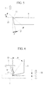
Fig. 3} Fig. 3 is a cross sectional view illustrating a state of machining the ordinary piping. - {
Fig. 4} Fig. 4 is a perspective view of a throw-away tip for use in the machining. - {
Fig. 5} Fig. 5 is a front elevational view illustrating a tool tip end portion of the throw-away tip for use in the machining. - {
Fig. 6} Fig. 6 is a block diagram illustrating a state of cutting by use of the throw-away tip. - {
Fig. 7} Fig. 7 shows a graph illustrating a relation between a rake angle of a cutting tool and hardness of a surface layer in a cutting test. - {
Fig. 8} Fig. 8 shows a graph illustrating a relation between a depth and hardness in the cutting test. - {
Fig. 9} Fig. 9 is a photograph showing a cross sectional microstructure in a vicinity of a surface of work material machined by use of a cutting tool whose rake angle is 14°. - {
Fig. 10} Fig. 10 is a photograph showing a cross sectional microstructure in a vicinity of a surface of the work material machined by use of a cutting tool whose rake angle is 35°. - {
Fig. 11} Fig. 11 is a photograph showing an observation result of EBSP in a vicinity of the surface of the work material machined by use of the cutting tool whose rake angle is 14°. - {
Fig. 12} Fig. 12 is a photograph showing an observation result of EBSP in a vicinity of the surface of the work material machined by use of the cutting tool whose rake angle is 35°. - Hereinafter, an embodiment according to the present invention will be explained with reference to
Fig. 1 to Fig. 12 .
Fig. 1 illustrates a content of a thinning process for ordinary piping in a pressurized-water nuclear plant utilizing a machining method for austenite stainless steel equipment and piping according to one embodiment of the present invention. - A primary system of the pressurized-water nuclear plant includes a piping system other than main coolant pipes through which primary coolant circulates, for example; a piping system that performs emergency reactor cooling and emergency boron injection at the time of a loss of primary cooling water accident and main steam pipe rupture; a piping system that supplies make-up water to maintain the volume of the primary coolant when the primary coolant is shrunk due to decrease in load; and a piping system that removes heat of the primary coolant after a reactor is stopped, and injects boric acid solution of a refueling water pump into the reactor so as to lower the temperature at the time of a loss of coolant accident. Piping utilized in these piping systems is referred to as ordinary piping in contrast with the main coolant pipes.
The above-mentionedordinary piping 1 is formed by austenite stainless steel such as SUS316 and SUS304. - The
ordinary piping 1 is joined through welding or the like into a piping system. At this time, in order to smooth a butt-welded portion of the weldedordinary piping 1, a thinning process for machining an inner face of joined portion thereof is performed. In this thinning process, the joined portion is machined to asurface 3 indicated in an alternate long and short dash line ofFig. 1 to align inner diameters of both ends of theordinary piping 1 with each other, so that the butt-welded portion of the weldedordinary piping 1 becomes smoothly continued. The cutting amount of this thinning process is 1 to 2 mm thick or so, for example. - As illustrated in
Fig. 2 andFig. 3 , the machining is performed by rotating theordinary piping 1 about an axial line thereof, and feeding a throw-away tip (a finishing-cut tool, a base-cut tool) 5 toward afeed direction 7.
Fig. 4 andFig. 5 illustrate the structure of the throw-away tip 5, andFig. 4 is a perspective view of the throw-away tip 5 andFig. 5 illustrates a tool tip end portion thereof.Fig. 6 illustrates a cutting state by use of the throw-away tip 5. - A
chip 9 is generated in front surface of the feed direction of the throw-away tip 5, and arake face 11 is provided for scooping thischip 9. An angle of this rake face 11 relative to avertical plane 13 is referred to as a rake angle α.
An angle of the tool tip end portion of the throw-away tip 5 is referred to as a tool angle β, and an angle for making space between the throw-away tip 5 and theordinary piping 1 that is work material is referred to as a relief angle δ. - The throw-
away tip 5 is fed in a depth-of-cutdirection 15 by a depth of cut (a depth of finishing cut, a depth of base cut) 17, and is also fed in thefeed direction 7, thereby carrying out the cutting with a predetermined depth of cut, and this process is repeatedly performed so as to accomplish the machining with a predetermined amount. -
Fig. 7 illustrates results in which the above-described thinning process was carried out with the throw-away tip 5 using various rake angles α, and hardness of a surface portion of each machined surface at that time was measured.
The hardness of each machined surface is measured by measuring the Vickers hardness at a load of 10gf.
The respective rake angles α of the throw-away tip 5 used in a test are 11°, 14°, 15°, 20°, 24°, 27°, 32° and 35°. - In various machining conditions, each cutting with the rake angles α of 11° to 27° was carried out in the following range: the cutting speed is 7 to 87 m/min, the depth of
cut 17 is 0.1 to 1 mm, and the feeding rate is 0.08 to 0.25 mm/r.
Using the same throw-away tip 5, a rough machining with the greater depth ofcut 17 was initially carried out, and thereafter a finishing cutting of approximately 1 mm or so is carried out with the smaller depth ofcut 17. - In various machining conditions, each cutting with the rake angles α of 32° and 35° was carried out in the following range: the machining speed is 18 to 35 m/min, the depth of
cut 17 is 0.1 to 0.2 mm, and the feeding rate is 0.08 to 0.13 mm/r.
The cutting with the rake angles α of 32° and 35° was carried out in such a manner that, after the cutting using the rake angles α of 11° to 27° was completed, the cutting was carried out by replacing the throw-away tip 5 whose rake angles α were of 32° and 35°. - Specifically, the cutting with the rake angles α of 32° and 35° was carried out by performing the rough machining using the rake angles α of 11° to 27°, and then performing a base cutting with the smaller depth of
cut 17 of approximate 1 mm or so, and thereafter further performing the cutting with the further smaller depth ofcut 17.
This base cutting using the rake angles α of 11° to 27° with the smaller depth ofcut 17 of approximate 1 mm or so serves as a base treatment process for the cutting using the throw-away tip 5 whose rake angles α were of 32° and 35°. - In the throw-
away tip 5 whose rake angles α is of 32° and 35° (the rake angle of +29° or more), the depth ofcut 17 is set to be 0.1 mm or more and 0.2 mm or less.
Work hardening due to a pretreatment process becomes significant, especially in a region from the surface to a depth of 0.1 mm; and if machining is carried out in a region less than this, abrasion of the tip end of the throw-away tip 5 is progressed, so that the tip end of the throw-away tip 5 becomes rounder and loses its sharpness. Thus, the depth ofcut 17 of less than 0.1 mm rather brings about hardening of the surface.
If the depth ofcut 17 exceeds 0.2 mm, cutting resistance acting from theordinary piping 1 on the throw-away tip 5 becomes greater, so that the cutting edge of the throw-away tip 5 is likely to be chipped, which requires more time and cost for maintenance thereof. - As apparent from
Fig. 7 , the throw-away tip 5 whose rake angles α are 11° to 27° exhibits the Vickers hardness of more than 320 HV even if the machining condition is changed.
To the contrary, with respect to the throw-away tip 5 whose rake angles α are 32° and 35°, the Vickers hardness never exceeds 300 HV even if the machining condition is changed, and this shows that the hardness of the surface is reduced, compared with the machining with the throw-way tip 5 whose rake angles α are 11° to 27°.
For example, connecting every median of hardness for the respective rake angles α, the rake angle α of 29° located approximately at the center between the rake angle α of 27° and the rake angle α of 32° exhibits the Vickers hardness of less than 300 HV. - If the rake angle is set to be as great as +29° or more, the shear angle of the
chip 9 becomes greater and the thickness of thechip 9 becomes thinner, so that cutting force (cutting resistance) required for the cutting becomes smaller. Accordingly, the cutting resistance acting on theordinary piping 1 is reduced, therefore it is understood that the hardening of the machined surface can be suppressed. -
Fig. 8 illustrates results in which the above-described thinning process was carried out by use of the throw-away tip 5 whose rake angles α are 14° and 35°, and each hardness of the machined faces in the depth direction at that time was measured.
The hardness measurement was carried out in such a manner that, measurements were made at ten points at a depth of 0.01 mm from the surface; and with respect to one of the above ten points, measurements were made at depths of 0.02 and 0.05 mm, along with at a pitch of 0.1 mm from 0.1 mm to 1.0 mm deep from the surface. The hardness of each machined surface was measured by measuring the Vickers hardness at a load of 10gf.
The same machining conditions for the throw-away tip 5 were used as those in the above description. - As apparent from
Fig. 8 , the hardness in the vicinity of the surface (within 0.01 mm depth) machined with the rake angle of 35° is reduced as much as approximately 100 HV, compared with the hardness of that with the rake angle of 14°.
In a region at a depth of 0.2 mm or more from the surface, both rake angles exhibit approximately the same hardness. This indicates the hardness of the base material.
From this, it is appreciated that the machining with the rake angle of 14° that is a conventional machining method causes the surface work hardening of as much as 200 HV or more from the original hardness of the base material due to the machining; to the contrary, in the machining with the rake angle of 35° by use of the machining method according to the present invention, the work hardening is significantly reduced due to the reduced cutting resistance. -
Fig. 9 and Fig. 10 are photographs, each showing a cross sectional microstructure in the vicinity of the surface of the work material that is one example ofFig. 7 .Fig. 9 shows the one with the rake angle α of 14° andFig. 10 shows the one with the rake angle α of 35°.
InFig. 9 , it is apparent that a large number of strain lines (slip lines) run obliquely at a small interval in the vicinity of the surface. Such a number of strain lines resulted from the machining indicates that the surface work hardening was caused due to the machining. This proves the results ofFig. 8 .
On the other hand, inFig. 10 , it is appreciated that such strain lines were hardly seen, so that the work hardening is significantly reduced because of the reduced cutting resistance, which proves the results ofFig. 8 . -
Fig. 11 andFig. 12 are photographs showing observation results of EBSP (Electron Back Scattering Pattern) in the vicinity of the surface of the work material.Fig. 11 shows the one with rake angle α of 14° andFig. 12 shows the one with the rake angle α of 35°.
In this analysis method, a crystal orientation for each crystal grain is distinguished by using a different color (by using a different color density inFig. 11 andFig. 12 ) - In
Fig. 11 , it is apparent that a thick layer of fine crystal grains is formed in the vicinity of the surface, and the fine crystal grains are refined thickly in the vicinity of the surface layer. Such thick refinement of crystal grains in the vicinity of the surface layer indicates that the cutting resistance was great, so that a thick deformation was generated in the vicinity of the surface layer. Specifically, the surface work hardening was caused due to the machining. This proves the results ofFig. 8 .
InFig. 12 , fine crystal grains were formed at a very shallow portion in the vicinity of the surface layer, but noticeable refinement could not be seen, as a whole. From this, it is appreciated that the work hardening was significantly reduced due to the reduced cutting resistance, which proves the results ofFig. 8 . - As described above, since the finishing treatment is carried out by the machining using the throw-
away tip 5 whose rake angle is of +29° or more, it is possible to securely keep the hardness of the finished surface to be less than 300 HV in terms of the Vickers hardness .
In order to securely keep the hardness of the surface layer to be less than 300 HV in terms of the Vickers hardness, the rake angle α may be set to be 30° or more, or 31° or more, for example. - It is possible to keep the hardness of the surface layer to be less than 300 HV in terms of the Vickers hardness only by use of the machining, as described above; that is, it is possible to finish the surface in a state having no SCC sensitivity, therefore, occurrence of SCC can be suppressed only by use of the machining, without requiring after treatment such as removal of the hardened layer by buffing, pickling, electrolytic grinding or the like and/or applying compressive stress by peening, heat treatment (by use of laser or the like, for example), which has conventionally been carried out.
As described above, only the machining is required, and such after treatment can be eliminated, thereby reducing working hours for the thinning process as well as cost therefor.
In addition, since the hardness of the surface layer is low, even if working such as welding that causes tensile stress is applied after the machining, it is possible to maintain the SCC resistance. - As described above, the machining includes the so-called base treatment process in which the machining using the throw-
away tip 5 whose rake angles α are 11° to 27° with the greater depth ofcut 17 is carried out prior to the cutting using the throw-away tip 5 whose rake angle α is +29° or more. By this, deep and quick cutting is carried out in advance in the so-called base treatment process of the machining with the greater depth ofcut 17, so that the cutting amount can be reduced by use of the throw-away tip 5 whose rake angle of +29° or more. It is possible to reduce the cutting amount by use of the throw-away tip 5 whose rake angle is +29° or more, for which the depth ofcut 17 cannot be greater in view of the durability, thereby enhancing efficiency of the machining. - Note that it is preferable that the depth of
cut 17 in the base treatment process is 1 mm or less, preferably 0.2 mm or more and 0.3 mm or less.
If the cutting with the depth ofcut 17 of more than 1 mm is carried out, the hardness of the machined surface becomes significantly high, so that it becomes difficult to make the hardness less than 300 HV in terms of the Vickers hardness even if the throw-away tip 5 whose rake angle α is +29° or more is used in the following cutting. Addition to this, it becomes difficult to apply the throw-away tip 5 whose tip end of the tool is very sharp and whose rake angle is +29° or more.
The depth ofcut 17 in the base treatment process is preferably set to be 0.2 mm or more and 0.3 mm or less because the hardness can be softened. - It is preferable that the treatment amount of the base treatment process is 0.5 mm thick or more and 2 mm thick or less, preferably 1 mm thick or so.
In the case where the treatment amount of the machining exceeds the above range, in consideration of the machining efficiency, it is preferable to perform a rough machining treatment process in which rough machining treatment is carried out with the greater depth ofcut 17 before the base treatment process. - Note that the present invention is not limited to the above explained embodiment, and various modifications may be made without departing from the spirit and scope of the present invention.
- For example, the present embodiment is applied to the thinning process of the ordinary piping in a pressurized-water nuclear plant, but is not limited to such thinning, and is also applicable to other machining for ordinary piping and others. It is also applicable to machining for piping in a secondary system or the like in a pressurized-water nuclear plant, and for recirculation piping or other piping in a boiling-reactor nuclear power plant. Furthermore, it is also applicable to machining for piping in a chemical plant or a thermal power plant, etc.
- It is not limited to machining for piping but is applicable to machining for various equipment and piping of austenite stainless steel such as plate material or block material.
In addition, it is also applicable to machining for material exhibiting the similar behavior to that of austenite stainless steel such as inconel that is a Nickel base alloy. -
- 1
- Ordinary piping
- 2
- Throw-away tip
- 3
- Depth of cut
Claims (6)
- A machining method for austenite stainless steel equipment and piping, comprising:a finishing treatment process for performing a machining operation by use of a finishing-cut tool whose rake angle is +29° or more to suppress work hardening of a surface.
- The machining method for austenite stainless steel equipment and piping according to claim 1, wherein
a depth of finishing cut for the finishing-cut tool is 0.1 mm or more and 0.2 mm or less. - The machining method for austenite stainless steel equipment and piping according to claim 2, comprising:a base treatment process for performing a machining operation by use of a base-cut tool whose rake angle is smaller than the rake angle of the finishing-cut tool with a depth of base cut that is a greater depth of cut than the depth of finishing cut, prior to the finishing treatment process.
- The machining method for austenite stainless steel equipment and piping according to claim 3, wherein
the depth of base cut is 1 mm or less, preferably 0.2 mm or more and 0.3 mm or less. - The machining method for austenite stainless steel equipment and piping according to claim 3 or claim 4, wherein
treatment amount of the base treatment process is 0.5 mm thick or more and 2 mm thick or less, preferably 1 mm thick or so. - Nuclear power plant equipment and piping machined by use of the machining method for austenite stainless steel equipment and piping according to any one of claims 1 to 5.
Applications Claiming Priority (3)
| Application Number | Priority Date | Filing Date | Title |
|---|---|---|---|
| JP2009198263 | 2009-08-28 | ||
| JP2009274517A JP5427575B2 (en) | 2009-08-28 | 2009-12-02 | Austenitic stainless steel equipment and piping cutting method, and nuclear plant equipment and piping machined using the same |
| PCT/JP2010/064010 WO2011024706A1 (en) | 2009-08-28 | 2010-08-19 | Method for machining austenite stainless steel equipment and piping, and nuclear power plant equipment and piping machined by means of said method |
Publications (3)
| Publication Number | Publication Date |
|---|---|
| EP2471616A1 true EP2471616A1 (en) | 2012-07-04 |
| EP2471616A4 EP2471616A4 (en) | 2013-10-30 |
| EP2471616B1 EP2471616B1 (en) | 2017-02-15 |
Family
ID=43627812
Family Applications (1)
| Application Number | Title | Priority Date | Filing Date |
|---|---|---|---|
| EP10811756.5A Active EP2471616B1 (en) | 2009-08-28 | 2010-08-19 | Method for machining austenite stainless steel equipment and piping, and nuclear power plant equipment and piping machined by means of said method |
Country Status (4)
| Country | Link |
|---|---|
| US (1) | US20120152400A1 (en) |
| EP (1) | EP2471616B1 (en) |
| JP (1) | JP5427575B2 (en) |
| WO (1) | WO2011024706A1 (en) |
Families Citing this family (4)
| Publication number | Priority date | Publication date | Assignee | Title |
|---|---|---|---|---|
| JP5752207B2 (en) * | 2009-08-28 | 2015-07-22 | 三菱重工業株式会社 | Austenitic stainless steel equipment and piping cutting method, and nuclear plant equipment and piping machined using the same |
| US10133428B2 (en) * | 2015-05-29 | 2018-11-20 | Samsung Display Co., Ltd. | Flexible display device including a flexible substrate having a bending part and a conductive pattern at least partially disposed on the bending part |
| RU2712678C1 (en) * | 2016-07-18 | 2020-01-30 | Майкро-Лэм, Инк. | Laser-transmitted instrument |
| DE102019116103B4 (en) * | 2019-06-13 | 2021-04-22 | Notion Systems GmbH | Method for labeling a printed circuit board by creating shading in a functional lacquer layer |
Family Cites Families (13)
| Publication number | Priority date | Publication date | Assignee | Title |
|---|---|---|---|---|
| US4417489A (en) * | 1979-12-21 | 1983-11-29 | Liu Chunghorng R | Method and apparatus for machining a workpiece by varying the tool geometry |
| JPS589786A (en) * | 1981-07-08 | 1983-01-20 | Hitachi Ltd | High frequency induction heating coil wound on joint of piping |
| CH671901A5 (en) * | 1987-06-25 | 1989-10-13 | Stellram Sa | |
| US5157997A (en) * | 1987-12-16 | 1992-10-27 | Ford Motor Company | Cutting tool for aluminum workpieces having enhanced crater wear resistance |
| JP2815533B2 (en) * | 1993-11-15 | 1998-10-27 | 京セラ株式会社 | Cutting equipment for milling |
| US6939090B1 (en) * | 1999-08-17 | 2005-09-06 | Mitsubishi Materials Corporation | Throwaway tip and throwaway-type cutting tool |
| US6395107B1 (en) * | 2000-01-28 | 2002-05-28 | Sundaresa V. Subramanian | Cast iron for use in high speed machining with cubic boron nitride and silicon nitride tools |
| JP2003191110A (en) * | 2001-12-21 | 2003-07-08 | Toshiba Tungaloy Co Ltd | Throwaway tip for face milling cutter |
| DE10341976A1 (en) * | 2003-09-11 | 2005-04-28 | Mapal Fab Praezision | Tool and method for machining fine machining of workpieces |
| DE202004002491U1 (en) * | 2004-02-17 | 2005-08-18 | Kennametal Inc. | Cutting plate, in particular for a boring tool |
| JP2006255793A (en) * | 2005-03-15 | 2006-09-28 | Hitachi Tool Engineering Ltd | End mill for cutting heat-resisting alloy |
| US7472464B2 (en) * | 2005-11-03 | 2009-01-06 | H&S Tool, Inc. | Milling head for removing heat dissipating elements from a tube |
| EP2060641B1 (en) * | 2006-08-23 | 2018-10-24 | Nkk Tubes | Austenite-base stainless steel pipe, for boiler, having excellent high-temperature steam oxidation resistance |
-
2009
- 2009-12-02 JP JP2009274517A patent/JP5427575B2/en active Active
-
2010
- 2010-08-19 US US13/391,983 patent/US20120152400A1/en not_active Abandoned
- 2010-08-19 WO PCT/JP2010/064010 patent/WO2011024706A1/en not_active Ceased
- 2010-08-19 EP EP10811756.5A patent/EP2471616B1/en active Active
Also Published As
| Publication number | Publication date |
|---|---|
| JP5427575B2 (en) | 2014-02-26 |
| WO2011024706A1 (en) | 2011-03-03 |
| EP2471616B1 (en) | 2017-02-15 |
| US20120152400A1 (en) | 2012-06-21 |
| JP2011067929A (en) | 2011-04-07 |
| EP2471616A4 (en) | 2013-10-30 |
Similar Documents
| Publication | Publication Date | Title |
|---|---|---|
| Ezugwu et al. | Surface integrity of finished turned Ti–6Al–4V alloy with PCD tools using conventional and high pressure coolant supplies | |
| Nath et al. | A study on ultrasonic vibration cutting of low alloy steel | |
| Kwong et al. | The sensitivity of Ni-based superalloy to hole making operations: Influence of process parameters on subsurface damage and residual stress | |
| Lauwers | Surface integrity in hybrid machining processes | |
| Yin et al. | Tool wear and its effect on the surface integrity and fatigue behavior in high-speed ultrasonic peening milling of Inconel 718 | |
| Herbert et al. | An evaluation of the evolution of workpiece surface integrity in hole making operations for a nickel-based superalloy | |
| EP2471616B1 (en) | Method for machining austenite stainless steel equipment and piping, and nuclear power plant equipment and piping machined by means of said method | |
| Anthony Xavior et al. | Experimental investigation of work hardening, residual stress and microstructure during machining Inconel 718 | |
| JPWO2016203924A1 (en) | Steel pipe for fuel injection pipe and manufacturing method thereof | |
| Bushlya et al. | Modeling and experimentation on multistage work-hardening mechanism in machining with nose-radiused tools and its influence on machined subsurface quality and tool wear | |
| Wang et al. | Effects of MQL on tool wear mechanisms in side milling of Ti2AlNb intermetallic alloys | |
| Tan et al. | Studies on surface integrity and fatigue performance of Ti-17 alloy induced by ultrasonic surface rolling process | |
| EP4470691A1 (en) | Method for performing shearing work on amorphous alloy foil | |
| JP5752207B2 (en) | Austenitic stainless steel equipment and piping cutting method, and nuclear plant equipment and piping machined using the same | |
| Guimaraes et al. | Evaluation of milling parameters on the surface integrity of welded inconel 625 | |
| Nakata et al. | Suppression of anisotropy by wire and arc additive manufacturing with finishing process | |
| Churi et al. | Rotary ultrasonic machining of titanium alloy: a feasibility study | |
| EP2636479A1 (en) | Machining condition setting system, machining condition setting method, and machined object which is machined using same | |
| CN103801903A (en) | Preparation method for anti-vibration bar assembly of steam generator of CAP1000 nuclear power unit | |
| Papageorgiou et al. | Failure analysis of a lancing tool used in a bridge slot filter pipe machine | |
| Krawczyk et al. | The Role of Lead in the Machinability of Copper Alloys Used for Drinking Water Installations | |
| Engelking et al. | Influence of Ultrasonic‐Assisted Milling on Surface Integrity and Fatigue Strength of a Low Alloy Steel | |
| Pfeiffer et al. | The effect of specimen size on residual stresses in friction stir welded aluminum components | |
| Cox | Understanding the effect of surface generation rates for finish milling of Ti-5Al-5Mo-5V-3Cr aero-structural components | |
| Xu et al. | Experimental Research on Material Removal Mechanism and Grinding Force of FeCoNiCrMo0. 1 High Entropy Alloy (HEA) |
Legal Events
| Date | Code | Title | Description |
|---|---|---|---|
| PUAI | Public reference made under article 153(3) epc to a published international application that has entered the european phase |
Free format text: ORIGINAL CODE: 0009012 |
|
| 17P | Request for examination filed |
Effective date: 20120224 |
|
| AK | Designated contracting states |
Kind code of ref document: A1 Designated state(s): AL AT BE BG CH CY CZ DE DK EE ES FI FR GB GR HR HU IE IS IT LI LT LU LV MC MK MT NL NO PL PT RO SE SI SK SM TR |
|
| DAX | Request for extension of the european patent (deleted) | ||
| A4 | Supplementary search report drawn up and despatched |
Effective date: 20131001 |
|
| RIC1 | Information provided on ipc code assigned before grant |
Ipc: B23B 1/00 20060101AFI20130925BHEP |
|
| 17Q | First examination report despatched |
Effective date: 20151103 |
|
| GRAJ | Information related to disapproval of communication of intention to grant by the applicant or resumption of examination proceedings by the epo deleted |
Free format text: ORIGINAL CODE: EPIDOSDIGR1 |
|
| GRAP | Despatch of communication of intention to grant a patent |
Free format text: ORIGINAL CODE: EPIDOSNIGR1 |
|
| GRAP | Despatch of communication of intention to grant a patent |
Free format text: ORIGINAL CODE: EPIDOSNIGR1 |
|
| INTG | Intention to grant announced |
Effective date: 20160914 |
|
| GRAS | Grant fee paid |
Free format text: ORIGINAL CODE: EPIDOSNIGR3 |
|
| GRAA | (expected) grant |
Free format text: ORIGINAL CODE: 0009210 |
|
| AK | Designated contracting states |
Kind code of ref document: B1 Designated state(s): AL AT BE BG CH CY CZ DE DK EE ES FI FR GB GR HR HU IE IS IT LI LT LU LV MC MK MT NL NO PL PT RO SE SI SK SM TR |
|
| REG | Reference to a national code |
Ref country code: CH Ref legal event code: EP Ref country code: GB Ref legal event code: FG4D |
|
| REG | Reference to a national code |
Ref country code: IE Ref legal event code: FG4D |
|
| REG | Reference to a national code |
Ref country code: AT Ref legal event code: REF Ref document number: 867616 Country of ref document: AT Kind code of ref document: T Effective date: 20170315 |
|
| REG | Reference to a national code |
Ref country code: DE Ref legal event code: R096 Ref document number: 602010040127 Country of ref document: DE |
|
| REG | Reference to a national code |
Ref country code: NL Ref legal event code: MP Effective date: 20170215 |
|
| REG | Reference to a national code |
Ref country code: LT Ref legal event code: MG4D |
|
| REG | Reference to a national code |
Ref country code: AT Ref legal event code: MK05 Ref document number: 867616 Country of ref document: AT Kind code of ref document: T Effective date: 20170215 |
|
| REG | Reference to a national code |
Ref country code: FR Ref legal event code: PLFP Year of fee payment: 8 |
|
| PG25 | Lapsed in a contracting state [announced via postgrant information from national office to epo] |
Ref country code: LT Free format text: LAPSE BECAUSE OF FAILURE TO SUBMIT A TRANSLATION OF THE DESCRIPTION OR TO PAY THE FEE WITHIN THE PRESCRIBED TIME-LIMIT Effective date: 20170215 Ref country code: GR Free format text: LAPSE BECAUSE OF FAILURE TO SUBMIT A TRANSLATION OF THE DESCRIPTION OR TO PAY THE FEE WITHIN THE PRESCRIBED TIME-LIMIT Effective date: 20170516 Ref country code: FI Free format text: LAPSE BECAUSE OF FAILURE TO SUBMIT A TRANSLATION OF THE DESCRIPTION OR TO PAY THE FEE WITHIN THE PRESCRIBED TIME-LIMIT Effective date: 20170215 Ref country code: NO Free format text: LAPSE BECAUSE OF FAILURE TO SUBMIT A TRANSLATION OF THE DESCRIPTION OR TO PAY THE FEE WITHIN THE PRESCRIBED TIME-LIMIT Effective date: 20170515 Ref country code: HR Free format text: LAPSE BECAUSE OF FAILURE TO SUBMIT A TRANSLATION OF THE DESCRIPTION OR TO PAY THE FEE WITHIN THE PRESCRIBED TIME-LIMIT Effective date: 20170215 |
|
| PG25 | Lapsed in a contracting state [announced via postgrant information from national office to epo] |
Ref country code: SE Free format text: LAPSE BECAUSE OF FAILURE TO SUBMIT A TRANSLATION OF THE DESCRIPTION OR TO PAY THE FEE WITHIN THE PRESCRIBED TIME-LIMIT Effective date: 20170215 Ref country code: AT Free format text: LAPSE BECAUSE OF FAILURE TO SUBMIT A TRANSLATION OF THE DESCRIPTION OR TO PAY THE FEE WITHIN THE PRESCRIBED TIME-LIMIT Effective date: 20170215 Ref country code: ES Free format text: LAPSE BECAUSE OF FAILURE TO SUBMIT A TRANSLATION OF THE DESCRIPTION OR TO PAY THE FEE WITHIN THE PRESCRIBED TIME-LIMIT Effective date: 20170215 Ref country code: BG Free format text: LAPSE BECAUSE OF FAILURE TO SUBMIT A TRANSLATION OF THE DESCRIPTION OR TO PAY THE FEE WITHIN THE PRESCRIBED TIME-LIMIT Effective date: 20170515 Ref country code: PT Free format text: LAPSE BECAUSE OF FAILURE TO SUBMIT A TRANSLATION OF THE DESCRIPTION OR TO PAY THE FEE WITHIN THE PRESCRIBED TIME-LIMIT Effective date: 20170615 Ref country code: LV Free format text: LAPSE BECAUSE OF FAILURE TO SUBMIT A TRANSLATION OF THE DESCRIPTION OR TO PAY THE FEE WITHIN THE PRESCRIBED TIME-LIMIT Effective date: 20170215 Ref country code: NL Free format text: LAPSE BECAUSE OF FAILURE TO SUBMIT A TRANSLATION OF THE DESCRIPTION OR TO PAY THE FEE WITHIN THE PRESCRIBED TIME-LIMIT Effective date: 20170215 |
|
| PG25 | Lapsed in a contracting state [announced via postgrant information from national office to epo] |
Ref country code: EE Free format text: LAPSE BECAUSE OF FAILURE TO SUBMIT A TRANSLATION OF THE DESCRIPTION OR TO PAY THE FEE WITHIN THE PRESCRIBED TIME-LIMIT Effective date: 20170215 Ref country code: RO Free format text: LAPSE BECAUSE OF FAILURE TO SUBMIT A TRANSLATION OF THE DESCRIPTION OR TO PAY THE FEE WITHIN THE PRESCRIBED TIME-LIMIT Effective date: 20170215 Ref country code: CZ Free format text: LAPSE BECAUSE OF FAILURE TO SUBMIT A TRANSLATION OF THE DESCRIPTION OR TO PAY THE FEE WITHIN THE PRESCRIBED TIME-LIMIT Effective date: 20170215 Ref country code: IT Free format text: LAPSE BECAUSE OF FAILURE TO SUBMIT A TRANSLATION OF THE DESCRIPTION OR TO PAY THE FEE WITHIN THE PRESCRIBED TIME-LIMIT Effective date: 20170215 Ref country code: SK Free format text: LAPSE BECAUSE OF FAILURE TO SUBMIT A TRANSLATION OF THE DESCRIPTION OR TO PAY THE FEE WITHIN THE PRESCRIBED TIME-LIMIT Effective date: 20170215 |
|
| REG | Reference to a national code |
Ref country code: DE Ref legal event code: R097 Ref document number: 602010040127 Country of ref document: DE |
|
| PG25 | Lapsed in a contracting state [announced via postgrant information from national office to epo] |
Ref country code: PL Free format text: LAPSE BECAUSE OF FAILURE TO SUBMIT A TRANSLATION OF THE DESCRIPTION OR TO PAY THE FEE WITHIN THE PRESCRIBED TIME-LIMIT Effective date: 20170215 Ref country code: DK Free format text: LAPSE BECAUSE OF FAILURE TO SUBMIT A TRANSLATION OF THE DESCRIPTION OR TO PAY THE FEE WITHIN THE PRESCRIBED TIME-LIMIT Effective date: 20170215 Ref country code: SM Free format text: LAPSE BECAUSE OF FAILURE TO SUBMIT A TRANSLATION OF THE DESCRIPTION OR TO PAY THE FEE WITHIN THE PRESCRIBED TIME-LIMIT Effective date: 20170215 |
|
| PLBE | No opposition filed within time limit |
Free format text: ORIGINAL CODE: 0009261 |
|
| STAA | Information on the status of an ep patent application or granted ep patent |
Free format text: STATUS: NO OPPOSITION FILED WITHIN TIME LIMIT |
|
| 26N | No opposition filed |
Effective date: 20171116 |
|
| PG25 | Lapsed in a contracting state [announced via postgrant information from national office to epo] |
Ref country code: SI Free format text: LAPSE BECAUSE OF FAILURE TO SUBMIT A TRANSLATION OF THE DESCRIPTION OR TO PAY THE FEE WITHIN THE PRESCRIBED TIME-LIMIT Effective date: 20170215 |
|
| REG | Reference to a national code |
Ref country code: DE Ref legal event code: R119 Ref document number: 602010040127 Country of ref document: DE |
|
| REG | Reference to a national code |
Ref country code: CH Ref legal event code: PL |
|
| PG25 | Lapsed in a contracting state [announced via postgrant information from national office to epo] |
Ref country code: MC Free format text: LAPSE BECAUSE OF FAILURE TO SUBMIT A TRANSLATION OF THE DESCRIPTION OR TO PAY THE FEE WITHIN THE PRESCRIBED TIME-LIMIT Effective date: 20170215 |
|
| GBPC | Gb: european patent ceased through non-payment of renewal fee |
Effective date: 20170819 |
|
| PG25 | Lapsed in a contracting state [announced via postgrant information from national office to epo] |
Ref country code: LI Free format text: LAPSE BECAUSE OF NON-PAYMENT OF DUE FEES Effective date: 20170831 Ref country code: CH Free format text: LAPSE BECAUSE OF NON-PAYMENT OF DUE FEES Effective date: 20170831 |
|
| REG | Reference to a national code |
Ref country code: IE Ref legal event code: MM4A |
|
| REG | Reference to a national code |
Ref country code: BE Ref legal event code: MM Effective date: 20170831 |
|
| PG25 | Lapsed in a contracting state [announced via postgrant information from national office to epo] |
Ref country code: LU Free format text: LAPSE BECAUSE OF NON-PAYMENT OF DUE FEES Effective date: 20170819 |
|
| REG | Reference to a national code |
Ref country code: FR Ref legal event code: PLFP Year of fee payment: 9 |
|
| PG25 | Lapsed in a contracting state [announced via postgrant information from national office to epo] |
Ref country code: GB Free format text: LAPSE BECAUSE OF NON-PAYMENT OF DUE FEES Effective date: 20170819 Ref country code: DE Free format text: LAPSE BECAUSE OF NON-PAYMENT OF DUE FEES Effective date: 20180301 Ref country code: IE Free format text: LAPSE BECAUSE OF NON-PAYMENT OF DUE FEES Effective date: 20170819 |
|
| PG25 | Lapsed in a contracting state [announced via postgrant information from national office to epo] |
Ref country code: BE Free format text: LAPSE BECAUSE OF NON-PAYMENT OF DUE FEES Effective date: 20170831 |
|
| PG25 | Lapsed in a contracting state [announced via postgrant information from national office to epo] |
Ref country code: MT Free format text: LAPSE BECAUSE OF NON-PAYMENT OF DUE FEES Effective date: 20170819 |
|
| PG25 | Lapsed in a contracting state [announced via postgrant information from national office to epo] |
Ref country code: HU Free format text: LAPSE BECAUSE OF FAILURE TO SUBMIT A TRANSLATION OF THE DESCRIPTION OR TO PAY THE FEE WITHIN THE PRESCRIBED TIME-LIMIT; INVALID AB INITIO Effective date: 20100819 |
|
| PG25 | Lapsed in a contracting state [announced via postgrant information from national office to epo] |
Ref country code: CY Free format text: LAPSE BECAUSE OF NON-PAYMENT OF DUE FEES Effective date: 20170215 |
|
| PG25 | Lapsed in a contracting state [announced via postgrant information from national office to epo] |
Ref country code: MK Free format text: LAPSE BECAUSE OF FAILURE TO SUBMIT A TRANSLATION OF THE DESCRIPTION OR TO PAY THE FEE WITHIN THE PRESCRIBED TIME-LIMIT Effective date: 20170215 |
|
| PG25 | Lapsed in a contracting state [announced via postgrant information from national office to epo] |
Ref country code: TR Free format text: LAPSE BECAUSE OF FAILURE TO SUBMIT A TRANSLATION OF THE DESCRIPTION OR TO PAY THE FEE WITHIN THE PRESCRIBED TIME-LIMIT Effective date: 20170215 |
|
| PG25 | Lapsed in a contracting state [announced via postgrant information from national office to epo] |
Ref country code: AL Free format text: LAPSE BECAUSE OF FAILURE TO SUBMIT A TRANSLATION OF THE DESCRIPTION OR TO PAY THE FEE WITHIN THE PRESCRIBED TIME-LIMIT Effective date: 20170215 Ref country code: IS Free format text: LAPSE BECAUSE OF FAILURE TO SUBMIT A TRANSLATION OF THE DESCRIPTION OR TO PAY THE FEE WITHIN THE PRESCRIBED TIME-LIMIT Effective date: 20170615 |
|
| P01 | Opt-out of the competence of the unified patent court (upc) registered |
Effective date: 20230522 |
|
| PGFP | Annual fee paid to national office [announced via postgrant information from national office to epo] |
Ref country code: FR Payment date: 20250703 Year of fee payment: 16 |