EP2471615A1 - System, method and apparatus for leaching cast components - Google Patents
System, method and apparatus for leaching cast components Download PDFInfo
- Publication number
- EP2471615A1 EP2471615A1 EP20110250949 EP11250949A EP2471615A1 EP 2471615 A1 EP2471615 A1 EP 2471615A1 EP 20110250949 EP20110250949 EP 20110250949 EP 11250949 A EP11250949 A EP 11250949A EP 2471615 A1 EP2471615 A1 EP 2471615A1
- Authority
- EP
- European Patent Office
- Prior art keywords
- cast component
- leaching solution
- solution
- high agitation
- shell
- Prior art date
- Legal status (The legal status is an assumption and is not a legal conclusion. Google has not performed a legal analysis and makes no representation as to the accuracy of the status listed.)
- Granted
Links
Images




Classifications
-
- B—PERFORMING OPERATIONS; TRANSPORTING
- B22—CASTING; POWDER METALLURGY
- B22D—CASTING OF METALS; CASTING OF OTHER SUBSTANCES BY THE SAME PROCESSES OR DEVICES
- B22D29/00—Removing castings from moulds, not restricted to casting processes covered by a single main group; Removing cores; Handling ingots
- B22D29/001—Removing cores
- B22D29/002—Removing cores by leaching, washing or dissolving
-
- B—PERFORMING OPERATIONS; TRANSPORTING
- B22—CASTING; POWDER METALLURGY
- B22D—CASTING OF METALS; CASTING OF OTHER SUBSTANCES BY THE SAME PROCESSES OR DEVICES
- B22D29/00—Removing castings from moulds, not restricted to casting processes covered by a single main group; Removing cores; Handling ingots
- B22D29/001—Removing cores
- B22D29/006—Removing cores by abrasive, water or air blasting
-
- C—CHEMISTRY; METALLURGY
- C23—COATING METALLIC MATERIAL; COATING MATERIAL WITH METALLIC MATERIAL; CHEMICAL SURFACE TREATMENT; DIFFUSION TREATMENT OF METALLIC MATERIAL; COATING BY VACUUM EVAPORATION, BY SPUTTERING, BY ION IMPLANTATION OR BY CHEMICAL VAPOUR DEPOSITION, IN GENERAL; INHIBITING CORROSION OF METALLIC MATERIAL OR INCRUSTATION IN GENERAL
- C23G—CLEANING OR DE-GREASING OF METALLIC MATERIAL BY CHEMICAL METHODS OTHER THAN ELECTROLYSIS
- C23G1/00—Cleaning or pickling metallic material with solutions or molten salts
Definitions
- a method includes removing a casting shell and core from a cast component, which may be a gas turbine blade.
- the method further includes utilizing a focused removal technique, such as a water jet or laser drill, to remove a portion of a virtual pattern cast (VPC) shell from the cast component.
- the cast component is then exposed to a leaching solution and high pressure water wash to remove an internal core material and a portion of the VPC shell remainder from the cast component.
- the method further includes exposing the cast component to a high agitation leaching solution and to the high pressure water wash for a minimal time.
- An electroless nickel-boron coating is then applied to the cast component, and an electrolytic palladium coating is further applied to the cast component.
- the cast component is further exposed to a high agitation leaching solution for an extended period.
- Fig. 1 is an illustrative cross-sectional view of a cast component 102 with a ceramic core 104 and ceramic shell 106.
- the cast component 102 further includes a plurality of discharge holes 108 for a cooling system (not shown) within the cast component 102.
- the cast component 102 is representative of a blade for a gas turbine engine. However, it is understood that any cast component 102 having a shell 106 and core 104 that require removal is contemplated for the present application.
- the cast component 102 may be a metal, and may further be a superalloy.
- the core 104 and shell 106 may be ceramic or any other material known in the art, and may be of any shape or configuration.
- Fig. 2 schematically illustrates a system 200 for leaching cast components 102.
- the system 200 includes a water jet 202 and/or a laser drill 204 adapted to remove at least a portion of a virtual pattern cast (VPC) shell 106 from a cast component 102.
- the water jet 202 and/or laser drill 204 may be utilized to increase surface area exposure of the shell 106 and/or core 104 to a subsequent chemical treatment.
- the shell 106 and core 104 may be ceramic, and the subsequent chemical treatment may include a caustic bath.
- the water jet 202 and/or laser drill 204 may break off bulk shell 106 pieces and penetrate the shell 106 and core 104 to increase exposure of the ceramic to the caustic bath.
- the system 200 further includes a submersion vessel 206 adapted to contain the cast component 102 and a quantity of a leaching solution 220, for example supplied by a caustic tank 208 and valve 210.
- the submersion vessel 206 is shown as a single batch vessel, but it is understood that the submersion vessel 206 may be a plurality of vessels, a continuous vessel such as a longer vessel with a conveyor, or any other type of vessel known in the art and adaptable to the present application as described herein.
- the leaching solution 220 may comprise any leaching solution understood in the art to remove casting shell 106 and core 104 material from a cast component 102.
- the leaching solution 220 may include one or more aqueous alkali hydroxides, alkaline solutions, acidic solutions, and/or solvents.
- the cast component 102 is a superalloy
- the core 104 and shell 106 material is a ceramic and/or intermetallic
- the leaching solution 220 comprises sodium hydroxide (NaOH), potassium hydroxide (KOH), and/or organic caustic solutions that further include ethanol or similar alcohols.
- the leaching solution 220 comprises a low concentration KOH, for example a KOH solution with a concentration below about 65% by weight KOH.
- the concentration that is a low concentration of KOH depends upon the specific application, but the low concentration is a concentration that is substantially lower than a saturated KOH solution.
- Exemplary low concentration values include a solution having a 20% lower KOH concentration than a subsequent high concentration KOH solution (e.g. reference the high agitation leaching solution 222), a solution having a substantially lower KOH concentration than a subsequent high concentration KOH solution, and/or a solution that provides enough activity with the shell 106 and core 104 material that a specified amount (e.g. 80%) of the bulk shell 106 and core 104 material is removed under the agitation conditions presented for a given embodiment.
- a specified amount e.g. 80%
- the solution strength that is a low concentration and that provides sufficient activity with the shell 106 and core 104 material is readily determined by one of skill in the art, having the benefit of the disclosures herein, for specified shell 106 and core 104 materials with a known agitation profile through simple empirical testing.
- the system 200 further includes a high pressure water wash 216 operable to wash the cast component 102 within the submersion vessel 206.
- the high pressure water wash 216 may comprise the same or similar equipment to the water jet 202, for example the water jet 202 may have a configurable nozzle with a more focused stream for the water jet 202 and a more diffuse stream for the high pressure water wash 216.
- the high pressure water wash 216 may operate with the cast component 102 immersed in the leaching solution 220 to enhance removal of the VPC shell 106 and core 104.
- the submersion vessel 206 may be further adapted to accept a heat input 212 and/or a pressure reduction - for example through a volume modulating unit 214 - to produce a high agitation leaching solution 222 in the submersion vessel 206.
- the high agitation leaching solution 222 may comprise any leaching material known in the art.
- the high agitation leaching solution 222 comprises a caustic solution that experiences intermittent boiling produced from the heat input 212 and/or through pressure reduction by the volume modulating unit 214.
- the heat input 212 may be any device or combination of devices known in the art to transfer heat to the high agitation leaching solution 222, including without limitation a heater, a burner, and a heat exchanger.
- the boiling of the caustic solution may increase the agitation and mass transfer of ceramic away from the shell 106 and core 104.
- an apparatus such as that described in U.S. Patent No. 6,739,380 to Schlienger et al. , incorporated herein by reference, may be utilized to produce the high agitation leaching solution 222.
- the high agitation leaching solution 222 may comprise a pre-agitation solution within a storage tank, and become the high agitation leaching solution 222 upon entry to the submersion vessel 206 and subsequent intermittent boiling.
- the high agitation leaching solution 222 may be a caustic solution with a high concentration KOH, for example a KOH solution with a concentration of about 82.3% KOH.
- the caustic solution provided for the high agitation leaching solution 222 may be provided by a second caustic tank 218 and may be the same or a separate caustic solution from the caustic tank 208 providing solution for the leaching solution 220.
- the high pressure water wash 216 may operate with the cast component 102 immersed in the high agitation leaching solution to enhance removal of the VPC shell 106 and core 104, resulting in reduced removal times of the remaining bulk shell 106 and core 104 materials.
- the system 200 further includes a high pressure water wash 216 operable to wash the cast component 102 within the submersion vessel 206.
- the high pressure water wash 216 may be operable while the high agitation caustic solution 222 is present in the submersion vessel 206.
- the cast component 102 may be exposed to the high agitation leaching solution 222 and the high pressure water wash 216 for a minimal time.
- a minimal time include a time known or estimated to be the lowest amount of time to achieve removal of the bulk of the VPC shell 106 and core 104 material, and/or to expose a large fraction of the cast component 102 surface. For example, a time that removes a selected fraction (e.g.
- VPC shell 106 and core 104 material 50% of the remaining VPC shell 106 and core 104 material may be a minimal time.
- a time that removes VPC shell 106 and core 104 material but that does not cause any observable degradation in the cast component 102 coating may be used as a maximum value for the minimal time.
- the time required to remove a selected fraction of the VPC shell 106 and core 104 material, and/or the time at which any observable degradation occurs on the cast component 102 coating depend upon specific factors such as the KOH concentration, the amount of agitation and the pressure of the high pressure water wash 216, and the time required is readily determined for a specific embodiment according to simple empirical testing by one of skill in the art having the benefit of the disclosures herein.
- the system 200 further includes an electroless nickel-boron coating solution 224 and a quantity of an electrolytic palladium coating solution 226.
- the cast component 102 may be immersed in the electroless nickel-boron coating solution 224 to place a nickel-boron coating on exposed surfaces of the cast component 102.
- the cast component 102 may then be immersed in the electrolytic palladium coating solution 226 to place a palladium coating on exposed surfaces of the cast component 102.
- the system 200 may further include electrical sources, valves and drains for switching fluids within the submersion vessel 206, and other components useful in draining the leaching solutions 220, 222 and placing the nickel-boron and palladium coatings.
- the system 200 further includes a second high agitation leaching solution 228, which may be the same or a different solution as the high agitation leaching solution 222, and may be supplied by a third caustic tank 230.
- the submersion vessel 206 is further adapted to contain the cast component 102 and the second high agitation leaching solution 228. In one embodiment, the submersion vessel 206 holds the cast component 102 in the second high agitation leaching solution 228 for an extended period - for example approximately three days.
- the system 200 further includes a peening instrument 232, for example a pneumatic bead gun - adapted to glass bead peen the cast component 102.
- the peening instrument 232 may utilize glass, ceramic, steel, aluminum, or any other peening material known in the art.
- the peening instrument 232 may peen the cast component 102 sufficiently to reduce porosity of the palladium coating and/or the nickel-boron coating on the cast component 102.
- the peening instrument 232 operates before the cast component 102 is submerged in the second high agitation leaching solution 228.
- One non-limiting embodiment of the present invention includes utilizing a focused removal technique to remove at least a portion of a virtual pattern case (VPC) shell from a cast component.
- the embodiment further includes exposing the cast component to a leaching solution and a high pressure water wash to remove an internal core material from the cast component and to remove at least a portion of the VPC shell remainder.
- the embodiment further includes exposing the cast component to a first high agitation leaching solution comprising a leaching solution subject to intermittent boiling. The intermittent boiling occurs through a temperature increase and/or a pressure decrease in a submersion vessel enclosing the first high agitation leaching solution.
- a further embodiment includes applying an electroless nickel-boron coating to the cast component, and applying an electrolytic palladium coating to the cast component.
- An embodiment further includes exposing the cast component to a second high agitation leaching solution to remove the VPC shell remainder and an internal core material remainder.
- Still another embodiment of the invention includes the focused removal technique comprising a water jet and/or a laser drill.
- Another embodiment includes the electroless nickel-boron coating comprising a thickness of between about 0.0002 inches (0.000508 centimetres) and 0.0003 inches (0.000762 centimetres), and in one embodiment the electrolytic palladium coating comprises a thickness of between about 0.0002 inches (0.000508 centimetres) and 0.0003 inches (0.000762 centimetres).
- a peening instrument peens the cast component with glass beads to reduce porosity in the nickel-boron and/or palladium coatings.
- a further embodiment of the invention includes exposing the cast component to a second high agitation leaching solution for approximately three days.
- the cast component is a superalloy gas turbine engine blade, and the VPC shell and internal core material are ceramic.
- the first and second high agitation leaching solutions include a high concentration KOH, and the leaching solution includes a low concentration KOH.
- the cast component is exposed to the high pressure wash with the first high agitation leaching solution, and the exposure to the first high agitation leaching solution is for a minimal time.
- An additional embodiment of the present invention includes a system having a water jet and/or laser drill adapted to remove at least a portion of a VPC shell from a cast component.
- a further embodiment includes a submersion vessel adapted to contain the cast component and a quantity of a leaching solution, and a high pressure wash operable to wash the cast component within the submersion vessel.
- the submersion vessel is adapted to accept a heat input and/or a pressure reduction to produce a first high agitation leaching solution.
- the submersion vessel is further adapted to contain a quantity of an electroless nickel-boron coating solution and a quantity of an electrolytic palladium coating solution.
- the submersion vessel is further adapted, in one embodiment, to contain the cast component and a second high agitation leaching solution for a period of approximately three days.
- a further embodiment of the invention provides a system, comprising: a focused removal means for removing at least a portion of a virtual pattern cast (VPC) shell from a cast component; a first caustic treatment means for exposing the cast component to a caustic bath and a high pressure water wash to remove an internal core material from the cast component and to remove at least a portion of a VPC shell remainder; at least one of a heating means and a pressure adjustment means for producing a high agitation caustic solution comprising a caustic solution subject to intermittent boiling; a second caustic treatment means for exposing the cast component to the high agitation caustic solution and to the high pressure water wash; an electroless coating means for applying an electroless nickel-boron coating to the cast component; an electrolytic coating means for applying an electrolytic palladium coating to the cast component; and a third caustic treatment means for exposing the cast component to the high agitation caustic solution for an extended period to remove the VPC shell remainder and an internal core material remainder.
Landscapes
- Engineering & Computer Science (AREA)
- Mechanical Engineering (AREA)
- Chemical & Material Sciences (AREA)
- Chemical Kinetics & Catalysis (AREA)
- General Chemical & Material Sciences (AREA)
- Materials Engineering (AREA)
- Metallurgy (AREA)
- Organic Chemistry (AREA)
- Turbine Rotor Nozzle Sealing (AREA)
- Chemically Coating (AREA)
Abstract
Description
- The present application claims the benefit of United States Provisional Patent Application No.
61/428,720 filed December 30, 2010 - One significant complication in modern casting processes is the removal of the casting shell and core from the cast component. Some modern casting processes utilize complex core designs for intricate castings plus core materials that are not easily destroyed relative to the cast component. For example, gas turbine engine blades often have cooling passages with very complex features, and may be superalloy products with a ceramic core. Some applications have stringent material property requirements, and are therefore not robust to any significant degradation of the cast component material during removal of the core and shell. However, commercial component manufacturing requires that core and shell materials be removed as quickly and inexpensively as possible. The present invention contemplates unique solutions to these and other problems.
- A method includes removing a casting shell and core from a cast component, which may be a gas turbine blade. The method further includes utilizing a focused removal technique, such as a water jet or laser drill, to remove a portion of a virtual pattern cast (VPC) shell from the cast component. The cast component is then exposed to a leaching solution and high pressure water wash to remove an internal core material and a portion of the VPC shell remainder from the cast component. The method further includes exposing the cast component to a high agitation leaching solution and to the high pressure water wash for a minimal time. An electroless nickel-boron coating is then applied to the cast component, and an electrolytic palladium coating is further applied to the cast component. The cast component is further exposed to a high agitation leaching solution for an extended period.
-
-
Fig. 1 is an illustrative cross-sectional view of a cast component with a ceramic core and ceramic shell. -
Fig. 2 schematically illustrates a system for leaching castings. -
Fig. 3A schematically illustrates an alternate embodiment of a system for leaching castings in a first state. -
Fig. 3B schematically illustrates an alternate embodiment of a system for leaching castings in a second state. -
Fig. 3C schematically illustrates an alternate embodiment of a system for leaching castings in a third state -
Fig 3D schematically illustrates an alternate embodiment of a system for leaching castings in a fourth state. -
Fig. 3E schematically illustrates an alternate embodiment of a system for leaching castings in a fifth state. -
Fig. 3F schematically illustrates an alternate embodiment of a system for leaching castings in a sixth state. -
Fig. 3G schematically illustrates an alternate embodiment of a system for leaching castings in a seventh state. - For the purposes of promoting an understanding of the principles of the invention, reference will now be made to the embodiments illustrated in the drawings and specific language will be used to describe the same. It will nevertheless be understood that no limitation of the scope of the invention is thereby intended, such alterations and further modifications in the illustrated embodiments, and that such further applications of the principles of the invention as illustrated therein as would normally occur to one skilled in the art to which the invention relates are contemplated and protected.
-
Fig. 1 is an illustrative cross-sectional view of acast component 102 with aceramic core 104 andceramic shell 106. Thecast component 102 further includes a plurality of discharge holes 108 for a cooling system (not shown) within thecast component 102. Thecast component 102 is representative of a blade for a gas turbine engine. However, it is understood that anycast component 102 having ashell 106 andcore 104 that require removal is contemplated for the present application. - A number of casting methods are known to those in the art, and any casting method producing a
cast component 102 with ashell 106 and acore 104 is contemplated for the present application. No further details of a casting process are included to avoid obscuring aspects of the present application. Thecast component 102 may be a metal, and may further be a superalloy. Thecore 104 andshell 106 may be ceramic or any other material known in the art, and may be of any shape or configuration. -
Fig. 2 schematically illustrates asystem 200 forleaching cast components 102. Thesystem 200 includes awater jet 202 and/or alaser drill 204 adapted to remove at least a portion of a virtual pattern cast (VPC)shell 106 from acast component 102. Thewater jet 202 and/orlaser drill 204 may be utilized to increase surface area exposure of theshell 106 and/orcore 104 to a subsequent chemical treatment. For example, theshell 106 andcore 104 may be ceramic, and the subsequent chemical treatment may include a caustic bath. Thewater jet 202 and/orlaser drill 204 may break offbulk shell 106 pieces and penetrate theshell 106 andcore 104 to increase exposure of the ceramic to the caustic bath. - The
system 200 further includes a submersion vessel 206 adapted to contain thecast component 102 and a quantity of aleaching solution 220, for example supplied by acaustic tank 208 andvalve 210. The submersion vessel 206 is shown as a single batch vessel, but it is understood that the submersion vessel 206 may be a plurality of vessels, a continuous vessel such as a longer vessel with a conveyor, or any other type of vessel known in the art and adaptable to the present application as described herein. Theleaching solution 220 may comprise any leaching solution understood in the art to removecasting shell 106 andcore 104 material from acast component 102. Theleaching solution 220 may include one or more aqueous alkali hydroxides, alkaline solutions, acidic solutions, and/or solvents. In one embodiment, thecast component 102 is a superalloy, thecore 104 andshell 106 material is a ceramic and/or intermetallic, and theleaching solution 220 comprises sodium hydroxide (NaOH), potassium hydroxide (KOH), and/or organic caustic solutions that further include ethanol or similar alcohols. In one embodiment, theleaching solution 220 comprises a low concentration KOH, for example a KOH solution with a concentration below about 65% by weight KOH. - The concentration that is a low concentration of KOH depends upon the specific application, but the low concentration is a concentration that is substantially lower than a saturated KOH solution. Exemplary low concentration values include a solution having a 20% lower KOH concentration than a subsequent high concentration KOH solution (e.g. reference the high agitation leaching solution 222), a solution having a substantially lower KOH concentration than a subsequent high concentration KOH solution, and/or a solution that provides enough activity with the
shell 106 andcore 104 material that a specified amount (e.g. 80%) of thebulk shell 106 andcore 104 material is removed under the agitation conditions presented for a given embodiment. The solution strength that is a low concentration and that provides sufficient activity with theshell 106 andcore 104 material is readily determined by one of skill in the art, having the benefit of the disclosures herein, for specifiedshell 106 andcore 104 materials with a known agitation profile through simple empirical testing. - The
system 200 further includes a highpressure water wash 216 operable to wash thecast component 102 within the submersion vessel 206. The highpressure water wash 216 may comprise the same or similar equipment to thewater jet 202, for example thewater jet 202 may have a configurable nozzle with a more focused stream for thewater jet 202 and a more diffuse stream for the highpressure water wash 216. The highpressure water wash 216 may operate with thecast component 102 immersed in theleaching solution 220 to enhance removal of theVPC shell 106 andcore 104. - The submersion vessel 206 may be further adapted to accept a
heat input 212 and/or a pressure reduction - for example through a volume modulating unit 214 - to produce a highagitation leaching solution 222 in the submersion vessel 206. The highagitation leaching solution 222 may comprise any leaching material known in the art. In one embodiment, the highagitation leaching solution 222 comprises a caustic solution that experiences intermittent boiling produced from theheat input 212 and/or through pressure reduction by thevolume modulating unit 214. Theheat input 212 may be any device or combination of devices known in the art to transfer heat to the highagitation leaching solution 222, including without limitation a heater, a burner, and a heat exchanger. The boiling of the caustic solution may increase the agitation and mass transfer of ceramic away from theshell 106 andcore 104. For example, an apparatus such as that described inU.S. Patent No. 6,739,380 to Schlienger et al. , incorporated herein by reference, may be utilized to produce the highagitation leaching solution 222. The highagitation leaching solution 222 may comprise a pre-agitation solution within a storage tank, and become the highagitation leaching solution 222 upon entry to the submersion vessel 206 and subsequent intermittent boiling. - The high
agitation leaching solution 222 may be a caustic solution with a high concentration KOH, for example a KOH solution with a concentration of about 82.3% KOH. The caustic solution provided for the highagitation leaching solution 222 may be provided by a secondcaustic tank 218 and may be the same or a separate caustic solution from thecaustic tank 208 providing solution for theleaching solution 220. The highpressure water wash 216 may operate with thecast component 102 immersed in the high agitation leaching solution to enhance removal of theVPC shell 106 andcore 104, resulting in reduced removal times of the remainingbulk shell 106 andcore 104 materials. - The
system 200 further includes a highpressure water wash 216 operable to wash thecast component 102 within the submersion vessel 206. The highpressure water wash 216 may be operable while the high agitationcaustic solution 222 is present in the submersion vessel 206. Thecast component 102 may be exposed to the highagitation leaching solution 222 and the highpressure water wash 216 for a minimal time. Non-limiting examples of a minimal time include a time known or estimated to be the lowest amount of time to achieve removal of the bulk of theVPC shell 106 andcore 104 material, and/or to expose a large fraction of thecast component 102 surface. For example, a time that removes a selected fraction (e.g. 50%) of the remainingVPC shell 106 andcore 104 material may be a minimal time. In another example, a time that removesVPC shell 106 andcore 104 material but that does not cause any observable degradation in thecast component 102 coating may be used as a maximum value for the minimal time. The time required to remove a selected fraction of theVPC shell 106 andcore 104 material, and/or the time at which any observable degradation occurs on thecast component 102 coating depend upon specific factors such as the KOH concentration, the amount of agitation and the pressure of the highpressure water wash 216, and the time required is readily determined for a specific embodiment according to simple empirical testing by one of skill in the art having the benefit of the disclosures herein. - The
system 200 further includes an electroless nickel-boron coating solution 224 and a quantity of an electrolyticpalladium coating solution 226. Thecast component 102 may be immersed in the electroless nickel-boron coating solution 224 to place a nickel-boron coating on exposed surfaces of thecast component 102. Thecast component 102 may then be immersed in the electrolyticpalladium coating solution 226 to place a palladium coating on exposed surfaces of thecast component 102. Thesystem 200 may further include electrical sources, valves and drains for switching fluids within the submersion vessel 206, and other components useful in draining theleaching solutions cast component 102 are well understood in the art and not shown inFigure 2 to avoid obscuring aspects of the present application. - The
system 200 further includes a second highagitation leaching solution 228, which may be the same or a different solution as the highagitation leaching solution 222, and may be supplied by a thirdcaustic tank 230. The submersion vessel 206 is further adapted to contain thecast component 102 and the second highagitation leaching solution 228. In one embodiment, the submersion vessel 206 holds thecast component 102 in the second highagitation leaching solution 228 for an extended period - for example approximately three days. - In one embodiment, the
system 200 further includes apeening instrument 232, for example a pneumatic bead gun - adapted to glass bead peen thecast component 102. Thepeening instrument 232 may utilize glass, ceramic, steel, aluminum, or any other peening material known in the art. Thepeening instrument 232 may peen thecast component 102 sufficiently to reduce porosity of the palladium coating and/or the nickel-boron coating on thecast component 102. Thepeening instrument 232 operates before thecast component 102 is submerged in the second highagitation leaching solution 228. -
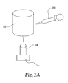
Fig. 3A schematically illustrates an alternate embodiment of a system for leaching castings in a first state. The embodiment illustrated inFig. 3A is consistent with thesystem 200 wherein thewater jet 202 andlaser drill 204 are utilized to remove at least a portion of aVPC shell 106 from acast component 102. The illustration ofFig. 3A shows awater jet 202 andlaser drill 204, but any focused removal technique understood in the art may be utilized for removing portions of theVPC shell 106. Removal of portions of theVPC shell 106 may further include opening up portions of thecore 104 for improved contact with aleaching solution -
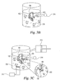
Fig. 3B schematically illustrates an alternate embodiment of a system for leaching castings in a second state. The embodiment illustrated inFig. 3B is consistent with thesystem 200 wherein the submersion vessel 206 is at least partially filled withleaching solution 220. Thecasting component 102 is illustrated within the submersion vessel 206, and a highpressure water wash 216 is working with theleaching solution 220 to remove aninternal core 104 material from thecast component 102, and further to remove at least a portion of theVPC shell 106 remainder. -
Fig. 3C schematically illustrates an alternate embodiment of a system for leaching castings in a third state. The embodiment illustrated inFig. 3C is consistent with thesystem 200 wherein the submersion vessel 206 is at least partially filled with a first highagitation leaching solution 222. The first highagitation leaching solution 222 may be aleaching solution 222 subject to intermittent boiling caused by aheat input 212 heating the first highagitation leaching solution 222 and/or avolume modulating unit 214 reducing the pressure in the submersion vessel 206 such that the first highagitation leaching solution 222 boils. In the embodiment ofFig. 3C , the highpressure water wash 216, which may be a second highpressure water wash 216, is also being utilized to enhance removal of thecore 104 andshell 106. The first highagitation leaching solution 222 and highpressure water wash 216 may be utilized together for a minimal time. The first highagitation leaching solution 222 may be a high concentration KOH solution.Fig. 3C includes an illustrated close-up showing nucleation sites of the boiling first highagitation leaching solution 222 attacking a remainder of theshell 106. -
Fig 3D schematically illustrates an alternate embodiment of a system for leaching castings in a fourth state. The embodiment illustrated inFig. 3D is consistent with thesystem 200 wherein the submersion vessel 206 is at least partially filled with an electroless nickel-boron coating solution 224 to apply an electroless nickel-boron coating to thecast component 102. The electroless nickel-boron coating may be applied to a thickness of between about 0.0002 inches (0.000508 centimetres) and 0.0003 inches (0.000762 centimetres). The thickness of the electroless nickel-boron coating may vary within any economic limits - for example where an aggressive caustic treatment is required including a long exposure time and/or a high concentration solution, a thicker coating may be applied. Where the caustic treatment is less aggressive a thinner and therefore less expensive nickel-boron coating may be applied. -
Fig. 3E schematically illustrates an alternate embodiment of a system for leaching castings in a fifth state. The embodiment illustrated inFig. 3E is consistent with thesystem 200 wherein the submersion vessel 206 is at least partially filled with anelectrolytic palladium solution 226 to apply an electrolytic palladium coating to thecast component 102. The electrolytic palladium coating may be applied to a thickness of between about 0.0002 inches (0.000508 centimetres) and 0.0003 inches (0.000762 centimetres). The thickness of the electrolytic palladium coating may vary within any economic limits - for example where an aggressive caustic treatment is required including a long exposure time and/or a high concentration solution, a thicker coating may be applied. Where the caustic treatment is less aggressive a thinner and therefore less expensive electrolytic palladium coating may be applied. -
Fig. 3F schematically illustrates an alternate embodiment of a system for leaching castings in a sixth state. The embodiment illustrated inFig. 3F is consistent with apeening instrument 232 peening thecast component 102 with glass beads to reduce any porosity within the electrolytic palladium coating and/or the electroless nickel-boron coating. -
Fig. 3G schematically illustrates an alternate embodiment of a system for leaching castings in a seventh state. The embodiment illustrated inFig. 3G is consistent with thesystem 200 wherein the submersion vessel 206 is at least partially filled with a second highagitation leaching solution 228. Thecasting component 102 is exposed to the second highagitation leaching solution 228 to remove theshell 106 remainder and thecore 104 remainder. The second highagitation leaching solution 228 may be a high concentration KOH solution, and may be the same or a different solution as the first highagitation leaching solution 222. Thecasting component 102 may remain in the second highagitation leaching solution 228 for an extended period, for example approximately three days. The second highagitation leaching solution 228 may be aleaching solution 228 subject to intermittent boiling caused by aheat input 212 heating the first highagitation leaching solution 222 and/or avolume modulating unit 214 reducing the pressure in the submersion vessel 206 such that the second highagitation leaching solution 228 boils.Fig. 3G includes an illustrated close-up showing nucleation sites of the boiling second highagitation leaching solution 228 attacking a remainder of theshell 106. - As is evident from the figures and text presented above, a variety of embodiments of the present application are contemplated. One non-limiting embodiment of the present invention includes utilizing a focused removal technique to remove at least a portion of a virtual pattern case (VPC) shell from a cast component. The embodiment further includes exposing the cast component to a leaching solution and a high pressure water wash to remove an internal core material from the cast component and to remove at least a portion of the VPC shell remainder. The embodiment further includes exposing the cast component to a first high agitation leaching solution comprising a leaching solution subject to intermittent boiling. The intermittent boiling occurs through a temperature increase and/or a pressure decrease in a submersion vessel enclosing the first high agitation leaching solution.
- A further embodiment includes applying an electroless nickel-boron coating to the cast component, and applying an electrolytic palladium coating to the cast component. An embodiment further includes exposing the cast component to a second high agitation leaching solution to remove the VPC shell remainder and an internal core material remainder.
- Still another embodiment of the invention includes the focused removal technique comprising a water jet and/or a laser drill. Another embodiment includes the electroless nickel-boron coating comprising a thickness of between about 0.0002 inches (0.000508 centimetres) and 0.0003 inches (0.000762 centimetres), and in one embodiment the electrolytic palladium coating comprises a thickness of between about 0.0002 inches (0.000508 centimetres) and 0.0003 inches (0.000762 centimetres). In a further contemplated embodiment, a peening instrument peens the cast component with glass beads to reduce porosity in the nickel-boron and/or palladium coatings.
- A further embodiment of the invention includes exposing the cast component to a second high agitation leaching solution for approximately three days. In a further embodiment, the cast component is a superalloy gas turbine engine blade, and the VPC shell and internal core material are ceramic. In a still further embodiment, the first and second high agitation leaching solutions include a high concentration KOH, and the leaching solution includes a low concentration KOH. In a still further embodiment, the cast component is exposed to the high pressure wash with the first high agitation leaching solution, and the exposure to the first high agitation leaching solution is for a minimal time.
- An additional embodiment of the present invention includes a system having a water jet and/or laser drill adapted to remove at least a portion of a VPC shell from a cast component. A further embodiment includes a submersion vessel adapted to contain the cast component and a quantity of a leaching solution, and a high pressure wash operable to wash the cast component within the submersion vessel. In a further embodiment, the submersion vessel is adapted to accept a heat input and/or a pressure reduction to produce a first high agitation leaching solution. In a still further embodiment, the submersion vessel is further adapted to contain a quantity of an electroless nickel-boron coating solution and a quantity of an electrolytic palladium coating solution. The submersion vessel is further adapted, in one embodiment, to contain the cast component and a second high agitation leaching solution for a period of approximately three days.
- A further embodiment of the invention provides a system, comprising: a focused removal means for removing at least a portion of a virtual pattern cast (VPC) shell from a cast component; a first caustic treatment means for exposing the cast component to a caustic bath and a high pressure water wash to remove an internal core material from the cast component and to remove at least a portion of a VPC shell remainder; at least one of a heating means and a pressure adjustment means for producing a high agitation caustic solution comprising a caustic solution subject to intermittent boiling; a second caustic treatment means for exposing the cast component to the high agitation caustic solution and to the high pressure water wash; an electroless coating means for applying an electroless nickel-boron coating to the cast component; an electrolytic coating means for applying an electrolytic palladium coating to the cast component; and a third caustic treatment means for exposing the cast component to the high agitation caustic solution for an extended period to remove the VPC shell remainder and an internal core material remainder.
- While the invention has been illustrated and described in detail in the drawings and foregoing description, the same is to be considered as illustrative and not restrictive in character, it being understood that only the preferred embodiments have been shown and described and that all changes and modifications that come within the spirit of the inventions are desired to be protected. It should be understood that while the use of words such as preferable, preferably, preferred, more preferred or exemplary utilized in the description above indicate that the feature so described may be more desirable or characteristic, nonetheless may not be necessary and embodiments lacking the same may be contemplated as within the scope of the invention, the scope being defined by the claims that follow. In reading the claims, it is intended that when words such as "a," "an," "at least one," or "at least one portion" are used there is no intention to limit the claim to only one item unless specifically stated to the contrary in the claim. When the language "at least a portion" and/or "a portion" is used the item can include a portion and/or the entire item unless specifically stated to the contrary.
Claims (18)
- A method, comprising:utilizing a focused removal technique to remove at least a portion of a virtual pattern cast (VPC) shell from a cast component;exposing the cast component to a leaching solution and a first high pressure water wash to remove an internal core material from the cast component and to remove at least a portion of a VPC shell remainder;exposing the cast component to a first high agitation leaching solution, the first high agitation leaching solution comprising a leaching solution subject to intermittent boiling caused by at least one of heating the first high agitation leaching solution and reducing a pressure in a submersion vessel;applying an electroless nickel-boron coating to the cast component;applying an electrolytic palladium coating to the cast component; andexposing the cast component to a second high agitation leaching solution to remove the VPC shell remainder and an internal core material remainder.
- The method of claim 1, wherein the focused removal technique comprises at least one of a water jet and a laser drill.
- The method of claim 1, further comprising peening the cast component with glass beads before exposing the cast component to the second high agitation leaching solution.
- The method of claim 1, wherein exposing the cast component to the second high agitation leaching solution comprises exposing the cast component to the high agitation leaching solution for approximately three days.
- The method of claim 1, further comprising exposing the cast component to a second high pressure water wash while exposing the cast component to the first high agitation leaching solution;
further comprising exposing the cast component to the first high agitation leaching solution for a minimal time. - The method of claim 1, wherein the leaching solution comprises a low concentration KOH solution.
- The method of claim 6, wherein the low concentration KOH solution comprises a solution of less than 65% KOH by weight.
- A method, comprising:utilizing at least one of a water jet removal and a laser drilling removal to remove at least a portion of a virtual pattern cast (VPC) shell from a cast component;exposing the cast component to a KOH bath and a high pressure water wash to remove an internal core material from the cast component and at least a portion of a VPC shell remainder;exposing the cast component to a high agitation KOH solution and the high pressure water wash, the high agitation KOH solution comprising a KOH solution subject to intermittent boiling caused by at least one of heating the KOH solution and reducing a pressure in a submersion vessel;applying an electroless nickel-boron coating to the cast component;applying an electrolytic palladium coating to the cast component; andexposing the cast component to the high agitation KOH solution to remove the VPC shell remainder and an internal core material remainder.
- The method of claim 8, further comprising peening the cast component with glass beads.
- The method of any preceding claim, wherein the electroless nickel-boron coating comprises a thickness of between about 0.000508 centimetres (0.0002 inches) and 0.000762 centimetres (0.0003 inches).
- The method of any preceding claim, wherein the electrolytic palladium coating comprises a thickness of between about 0.000508 centimetres (0.0002 inches) and 0.000762 centimetres (0.0003 inches).
- A system, comprising:a water jet and a laser drill adapted to remove at least a portion of a virtual pattern cast (VPC) shell from a cast component;a submersion vessel adapted to contain the cast component and a quantity of a leaching solution;a high pressure water wash operable to wash the cast component within the submersion vessel;the submersion vessel further adapted to accept at least one of a heat input and a pressure reduction to produce a first high agitation leaching solution;the submersion vessel further adapted to contain a quantity of an electroless nickel-boron coating solution and a quantity of an electrolytic palladium coating solution; andthe submersion vessel further adapted to contain the cast component and a second high agitation leaching solution for a period of approximately 3 days.
- The system of claim 12, further comprising a peening instrument adapted to peen the cast component; and
wherein the peening instrument utilizes a peening projectile comprising a member selected from the group consisting of glass, ceramic, steel, and aluminum. - The system of claim 12, wherein the high agitation leaching solution comprises a leaching solution experiencing intermittent boiling produced from the at least one of a heat input and a pressure reduction; and
wherein the leaching solution, first high agitation leaching solution, and second high agitation leaching solution each comprise potassium hydroxide (KOH). - The system of claim 14, wherein the leaching solution comprises a low concentration KOH, and wherein the first high agitation leaching solution and second high agitation leaching solution each comprise a high concentration KOH.
- The system of claim 15, wherein the high concentration KOH comprises about 82.3% potassium hydroxide by weight; or
wherein the high concentration KOH comprises greater than about 65% potassium hydroxide by weight. - The method of any one of claims 1 to 11 or the system of any one of claims 12 to 16, wherein the cast component comprises a superalloy, and wherein the VPC shell and internal core material comprise a ceramic.
- The method of any one of claims 1 to 11 or the system of any one of claims 12 to 17, wherein the cast component comprises a casting of a gas turbine engine blade.
Applications Claiming Priority (1)
| Application Number | Priority Date | Filing Date | Title |
|---|---|---|---|
| US201061428720P | 2010-12-30 | 2010-12-30 |
Publications (2)
| Publication Number | Publication Date |
|---|---|
| EP2471615A1 true EP2471615A1 (en) | 2012-07-04 |
| EP2471615B1 EP2471615B1 (en) | 2020-02-26 |
Family
ID=45478175
Family Applications (1)
| Application Number | Title | Priority Date | Filing Date |
|---|---|---|---|
| EP11250949.2A Active EP2471615B1 (en) | 2010-12-30 | 2011-12-29 | Method for leaching cast components |
Country Status (2)
| Country | Link |
|---|---|
| US (1) | US8828214B2 (en) |
| EP (1) | EP2471615B1 (en) |
Families Citing this family (6)
| Publication number | Priority date | Publication date | Assignee | Title |
|---|---|---|---|---|
| US9470105B2 (en) | 2013-11-21 | 2016-10-18 | General Electric Company | Automated water wash system for a gas turbine engine |
| US20150174653A1 (en) | 2013-12-19 | 2015-06-25 | United Technologies Corporation | System and methods for removing core elements of cast components |
| US9649687B2 (en) * | 2014-06-20 | 2017-05-16 | United Technologies Corporation | Method including fiber reinforced casting article |
| GB201708641D0 (en) * | 2017-05-31 | 2017-07-12 | Leed And Bradford Boiler Company Ltd | Autoclave system and method |
| CN107350457B (en) * | 2017-06-13 | 2019-03-01 | 西安交通大学 | A high-efficiency cleaning and de-coreding device for hollow turbine blades |
| US11813665B2 (en) | 2020-09-14 | 2023-11-14 | General Electric Company | Methods for casting a component having a readily removable casting core |
Citations (9)
| Publication number | Priority date | Publication date | Assignee | Title |
|---|---|---|---|---|
| US4439241A (en) * | 1982-03-01 | 1984-03-27 | United Technologies Corporation | Cleaning process for internal passages of superalloy airfoils |
| GB2266677A (en) * | 1992-05-08 | 1993-11-10 | Rolls Royce Plc | A method of leaching ceramic, eg alumina, cores from turbine blade castings |
| US5778963A (en) * | 1996-08-30 | 1998-07-14 | United Technologies Corporation | Method of core leach |
| EP0922514A2 (en) * | 1995-05-22 | 1999-06-16 | Howmet Corporation | Apparatus for removing ceramic shell mold material from castings by caustic spraying |
| US20020100492A1 (en) * | 2001-01-29 | 2002-08-01 | Risbeck James D. | Method of cleaning turbine component using laser shock peening |
| EP1358958A1 (en) * | 2002-04-25 | 2003-11-05 | General Electric Company | A way to manufacture inserts for steam cooled hot gas path components |
| US20040003909A1 (en) * | 2002-04-11 | 2004-01-08 | Schlienger Max Eric | Method and apparatus for removing ceramic material from cast components |
| WO2011017641A1 (en) * | 2009-08-06 | 2011-02-10 | Rolls-Royce Corporation | Systems and methods for leaching a material from an object |
| WO2011019667A1 (en) * | 2009-08-09 | 2011-02-17 | Rolls-Royce Corporation | Corrosion resistance for a leaching process |
Family Cites Families (16)
| Publication number | Priority date | Publication date | Assignee | Title |
|---|---|---|---|---|
| US3528861A (en) * | 1968-05-23 | 1970-09-15 | United Aircraft Corp | Method for coating the superalloys |
| US4055706A (en) * | 1974-07-16 | 1977-10-25 | Office National D'etudes Et De Recherches Aerospatiales (O.N.E.R.A.) | Processes for protecting refractory metallic components against corrosion |
| US4073662A (en) | 1977-03-09 | 1978-02-14 | General Electric Company | Method for removing a magnesia doped alumina core material |
| US4141781A (en) | 1977-10-06 | 1979-02-27 | General Electric Company | Method for rapid removal of cores made of βAl2 O3 from directionally solidified eutectic and superalloy and superalloy materials |
| US4317685A (en) | 1980-06-06 | 1982-03-02 | General Electric Company | Method for removing a scale from a superalloy surface |
| GB2084895A (en) | 1980-10-04 | 1982-04-21 | Rolls Royce | Dissolving refractory materials in particular cores from castings |
| US6241000B1 (en) | 1995-06-07 | 2001-06-05 | Howmet Research Corporation | Method for removing cores from castings |
| US5685917A (en) | 1995-12-26 | 1997-11-11 | General Electric Company | Method for cleaning cracks and surfaces of airfoils |
| US5779809A (en) | 1995-12-26 | 1998-07-14 | General Electric Company | Method of dissolving or leaching ceramic cores in airfoils |
| US6354310B1 (en) | 1998-11-12 | 2002-03-12 | General Electric Company | Apparatus and process to clean and strip coatings from hardware |
| US6474348B1 (en) | 1999-09-30 | 2002-11-05 | Howmet Research Corporation | CNC core removal from casting passages |
| US6475289B2 (en) | 2000-12-19 | 2002-11-05 | Howmet Research Corporation | Cleaning of internal passages of airfoils |
| US6974636B2 (en) * | 2003-09-22 | 2005-12-13 | General Electric Company | Protective coating for turbine engine component |
| DE102004021926A1 (en) * | 2004-05-04 | 2005-12-01 | Mtu Aero Engines Gmbh | A method of making a coating and anode for use in such a method |
| US6878215B1 (en) | 2004-05-27 | 2005-04-12 | General Electric Company | Chemical removal of a metal oxide coating from a superalloy article |
| US7341427B2 (en) * | 2005-12-20 | 2008-03-11 | General Electric Company | Gas turbine nozzle segment and process therefor |
-
2011
- 2011-12-28 US US13/338,811 patent/US8828214B2/en active Active
- 2011-12-29 EP EP11250949.2A patent/EP2471615B1/en active Active
Patent Citations (10)
| Publication number | Priority date | Publication date | Assignee | Title |
|---|---|---|---|---|
| US4439241A (en) * | 1982-03-01 | 1984-03-27 | United Technologies Corporation | Cleaning process for internal passages of superalloy airfoils |
| GB2266677A (en) * | 1992-05-08 | 1993-11-10 | Rolls Royce Plc | A method of leaching ceramic, eg alumina, cores from turbine blade castings |
| EP0922514A2 (en) * | 1995-05-22 | 1999-06-16 | Howmet Corporation | Apparatus for removing ceramic shell mold material from castings by caustic spraying |
| US5778963A (en) * | 1996-08-30 | 1998-07-14 | United Technologies Corporation | Method of core leach |
| US20020100492A1 (en) * | 2001-01-29 | 2002-08-01 | Risbeck James D. | Method of cleaning turbine component using laser shock peening |
| US20040003909A1 (en) * | 2002-04-11 | 2004-01-08 | Schlienger Max Eric | Method and apparatus for removing ceramic material from cast components |
| US6739380B2 (en) | 2002-04-11 | 2004-05-25 | Rolls-Royce Corporation | Method and apparatus for removing ceramic material from cast components |
| EP1358958A1 (en) * | 2002-04-25 | 2003-11-05 | General Electric Company | A way to manufacture inserts for steam cooled hot gas path components |
| WO2011017641A1 (en) * | 2009-08-06 | 2011-02-10 | Rolls-Royce Corporation | Systems and methods for leaching a material from an object |
| WO2011019667A1 (en) * | 2009-08-09 | 2011-02-17 | Rolls-Royce Corporation | Corrosion resistance for a leaching process |
Also Published As
| Publication number | Publication date |
|---|---|
| US20120222961A1 (en) | 2012-09-06 |
| US8828214B2 (en) | 2014-09-09 |
| EP2471615B1 (en) | 2020-02-26 |
Similar Documents
| Publication | Publication Date | Title |
|---|---|---|
| US8828214B2 (en) | System, method, and apparatus for leaching cast components | |
| EP1782899B1 (en) | Method for casting core removal | |
| CN103252477B (en) | Efficient ceramic core removal device for hollow blade | |
| TWI629409B (en) | Method for repairing turbine blades | |
| US20170239717A1 (en) | System and methods for removing core elements of cast components | |
| JPH0141710B2 (en) | ||
| US8409493B2 (en) | Systems and methods for leaching a material from an object | |
| US8091610B2 (en) | Method and apparatus for removing core material | |
| ES2275138T3 (en) | EXTRACTION PROCEDURE OF A COMPONENT MOVIE AREA. | |
| CN105618721B (en) | The core-removing device and depoling method of a kind of alumina ceramic core | |
| EP2865785B1 (en) | Thermal barrier coating removal process | |
| CN107855503A (en) | A kind of depoling equipment that alumina based ceramic core removing speed is improved by airflow stirring | |
| US20170370005A1 (en) | Additive manufacturing processing with oxidation | |
| CN104342713A (en) | Method removing aluminum oxide-titanium oxide ceramic seal coating | |
| US3546084A (en) | Cleaning method for jet engine parts | |
| CN105964937B (en) | A kind of removing means of the hollow turbine vane ceramic core based on heat convection principle | |
| EP2239063B1 (en) | Method and apparatus for cleaning a component using microwave radiation | |
| EP3315744B1 (en) | Turbine blade maintenance method | |
| US3698467A (en) | Method of removing silaceous cores from nickel and cobalt superalloy castings | |
| CN100366366C (en) | Tech. for removing sand by high temp. alkaline explosion | |
| RU2557119C1 (en) | Removal of ceramic material from parts casts | |
| CN102995042B (en) | Chemical oil removal device capable of supplementing active ingredients | |
| CN107829090A (en) | The removal methods of DLC coatings | |
| CN107127323B (en) | A method and equipment capable of improving the efficiency of ceramic core removal | |
| CN111097880B (en) | Method for removing silicon-based mold core in inner cavity of blade |
Legal Events
| Date | Code | Title | Description |
|---|---|---|---|
| AK | Designated contracting states |
Kind code of ref document: A1 Designated state(s): AL AT BE BG CH CY CZ DE DK EE ES FI FR GB GR HR HU IE IS IT LI LT LU LV MC MK MT NL NO PL PT RO RS SE SI SK SM TR |
|
| AX | Request for extension of the european patent |
Extension state: BA ME |
|
| PUAI | Public reference made under article 153(3) epc to a published international application that has entered the european phase |
Free format text: ORIGINAL CODE: 0009012 |
|
| 17P | Request for examination filed |
Effective date: 20130102 |
|
| 17Q | First examination report despatched |
Effective date: 20130213 |
|
| STAA | Information on the status of an ep patent application or granted ep patent |
Free format text: STATUS: EXAMINATION IS IN PROGRESS |
|
| GRAP | Despatch of communication of intention to grant a patent |
Free format text: ORIGINAL CODE: EPIDOSNIGR1 |
|
| STAA | Information on the status of an ep patent application or granted ep patent |
Free format text: STATUS: GRANT OF PATENT IS INTENDED |
|
| INTG | Intention to grant announced |
Effective date: 20190924 |
|
| GRAS | Grant fee paid |
Free format text: ORIGINAL CODE: EPIDOSNIGR3 |
|
| GRAA | (expected) grant |
Free format text: ORIGINAL CODE: 0009210 |
|
| STAA | Information on the status of an ep patent application or granted ep patent |
Free format text: STATUS: THE PATENT HAS BEEN GRANTED |
|
| AK | Designated contracting states |
Kind code of ref document: B1 Designated state(s): AL AT BE BG CH CY CZ DE DK EE ES FI FR GB GR HR HU IE IS IT LI LT LU LV MC MK MT NL NO PL PT RO RS SE SI SK SM TR |
|
| REG | Reference to a national code |
Ref country code: GB Ref legal event code: FG4D |
|
| REG | Reference to a national code |
Ref country code: CH Ref legal event code: EP |
|
| REG | Reference to a national code |
Ref country code: DE Ref legal event code: R096 Ref document number: 602011065198 Country of ref document: DE |
|
| REG | Reference to a national code |
Ref country code: AT Ref legal event code: REF Ref document number: 1237015 Country of ref document: AT Kind code of ref document: T Effective date: 20200315 |
|
| REG | Reference to a national code |
Ref country code: IE Ref legal event code: FG4D |
|
| PG25 | Lapsed in a contracting state [announced via postgrant information from national office to epo] |
Ref country code: NO Free format text: LAPSE BECAUSE OF FAILURE TO SUBMIT A TRANSLATION OF THE DESCRIPTION OR TO PAY THE FEE WITHIN THE PRESCRIBED TIME-LIMIT Effective date: 20200526 Ref country code: FI Free format text: LAPSE BECAUSE OF FAILURE TO SUBMIT A TRANSLATION OF THE DESCRIPTION OR TO PAY THE FEE WITHIN THE PRESCRIBED TIME-LIMIT Effective date: 20200226 Ref country code: RS Free format text: LAPSE BECAUSE OF FAILURE TO SUBMIT A TRANSLATION OF THE DESCRIPTION OR TO PAY THE FEE WITHIN THE PRESCRIBED TIME-LIMIT Effective date: 20200226 |
|
| REG | Reference to a national code |
Ref country code: NL Ref legal event code: MP Effective date: 20200226 |
|
| REG | Reference to a national code |
Ref country code: LT Ref legal event code: MG4D |
|
| PG25 | Lapsed in a contracting state [announced via postgrant information from national office to epo] |
Ref country code: HR Free format text: LAPSE BECAUSE OF FAILURE TO SUBMIT A TRANSLATION OF THE DESCRIPTION OR TO PAY THE FEE WITHIN THE PRESCRIBED TIME-LIMIT Effective date: 20200226 Ref country code: GR Free format text: LAPSE BECAUSE OF FAILURE TO SUBMIT A TRANSLATION OF THE DESCRIPTION OR TO PAY THE FEE WITHIN THE PRESCRIBED TIME-LIMIT Effective date: 20200527 Ref country code: IS Free format text: LAPSE BECAUSE OF FAILURE TO SUBMIT A TRANSLATION OF THE DESCRIPTION OR TO PAY THE FEE WITHIN THE PRESCRIBED TIME-LIMIT Effective date: 20200626 Ref country code: BG Free format text: LAPSE BECAUSE OF FAILURE TO SUBMIT A TRANSLATION OF THE DESCRIPTION OR TO PAY THE FEE WITHIN THE PRESCRIBED TIME-LIMIT Effective date: 20200526 Ref country code: SE Free format text: LAPSE BECAUSE OF FAILURE TO SUBMIT A TRANSLATION OF THE DESCRIPTION OR TO PAY THE FEE WITHIN THE PRESCRIBED TIME-LIMIT Effective date: 20200226 Ref country code: LV Free format text: LAPSE BECAUSE OF FAILURE TO SUBMIT A TRANSLATION OF THE DESCRIPTION OR TO PAY THE FEE WITHIN THE PRESCRIBED TIME-LIMIT Effective date: 20200226 |
|
| PG25 | Lapsed in a contracting state [announced via postgrant information from national office to epo] |
Ref country code: NL Free format text: LAPSE BECAUSE OF FAILURE TO SUBMIT A TRANSLATION OF THE DESCRIPTION OR TO PAY THE FEE WITHIN THE PRESCRIBED TIME-LIMIT Effective date: 20200226 |
|
| PG25 | Lapsed in a contracting state [announced via postgrant information from national office to epo] |
Ref country code: RO Free format text: LAPSE BECAUSE OF FAILURE TO SUBMIT A TRANSLATION OF THE DESCRIPTION OR TO PAY THE FEE WITHIN THE PRESCRIBED TIME-LIMIT Effective date: 20200226 Ref country code: EE Free format text: LAPSE BECAUSE OF FAILURE TO SUBMIT A TRANSLATION OF THE DESCRIPTION OR TO PAY THE FEE WITHIN THE PRESCRIBED TIME-LIMIT Effective date: 20200226 Ref country code: CZ Free format text: LAPSE BECAUSE OF FAILURE TO SUBMIT A TRANSLATION OF THE DESCRIPTION OR TO PAY THE FEE WITHIN THE PRESCRIBED TIME-LIMIT Effective date: 20200226 Ref country code: DK Free format text: LAPSE BECAUSE OF FAILURE TO SUBMIT A TRANSLATION OF THE DESCRIPTION OR TO PAY THE FEE WITHIN THE PRESCRIBED TIME-LIMIT Effective date: 20200226 Ref country code: PT Free format text: LAPSE BECAUSE OF FAILURE TO SUBMIT A TRANSLATION OF THE DESCRIPTION OR TO PAY THE FEE WITHIN THE PRESCRIBED TIME-LIMIT Effective date: 20200719 Ref country code: ES Free format text: LAPSE BECAUSE OF FAILURE TO SUBMIT A TRANSLATION OF THE DESCRIPTION OR TO PAY THE FEE WITHIN THE PRESCRIBED TIME-LIMIT Effective date: 20200226 Ref country code: SK Free format text: LAPSE BECAUSE OF FAILURE TO SUBMIT A TRANSLATION OF THE DESCRIPTION OR TO PAY THE FEE WITHIN THE PRESCRIBED TIME-LIMIT Effective date: 20200226 Ref country code: LT Free format text: LAPSE BECAUSE OF FAILURE TO SUBMIT A TRANSLATION OF THE DESCRIPTION OR TO PAY THE FEE WITHIN THE PRESCRIBED TIME-LIMIT Effective date: 20200226 Ref country code: SM Free format text: LAPSE BECAUSE OF FAILURE TO SUBMIT A TRANSLATION OF THE DESCRIPTION OR TO PAY THE FEE WITHIN THE PRESCRIBED TIME-LIMIT Effective date: 20200226 |
|
| REG | Reference to a national code |
Ref country code: AT Ref legal event code: MK05 Ref document number: 1237015 Country of ref document: AT Kind code of ref document: T Effective date: 20200226 |
|
| REG | Reference to a national code |
Ref country code: DE Ref legal event code: R097 Ref document number: 602011065198 Country of ref document: DE |
|
| PLBE | No opposition filed within time limit |
Free format text: ORIGINAL CODE: 0009261 |
|
| STAA | Information on the status of an ep patent application or granted ep patent |
Free format text: STATUS: NO OPPOSITION FILED WITHIN TIME LIMIT |
|
| PG25 | Lapsed in a contracting state [announced via postgrant information from national office to epo] |
Ref country code: AT Free format text: LAPSE BECAUSE OF FAILURE TO SUBMIT A TRANSLATION OF THE DESCRIPTION OR TO PAY THE FEE WITHIN THE PRESCRIBED TIME-LIMIT Effective date: 20200226 |
|
| 26N | No opposition filed |
Effective date: 20201127 |
|
| PG25 | Lapsed in a contracting state [announced via postgrant information from national office to epo] |
Ref country code: PL Free format text: LAPSE BECAUSE OF FAILURE TO SUBMIT A TRANSLATION OF THE DESCRIPTION OR TO PAY THE FEE WITHIN THE PRESCRIBED TIME-LIMIT Effective date: 20200226 Ref country code: SI Free format text: LAPSE BECAUSE OF FAILURE TO SUBMIT A TRANSLATION OF THE DESCRIPTION OR TO PAY THE FEE WITHIN THE PRESCRIBED TIME-LIMIT Effective date: 20200226 |
|
| REG | Reference to a national code |
Ref country code: DE Ref legal event code: R119 Ref document number: 602011065198 Country of ref document: DE |
|
| REG | Reference to a national code |
Ref country code: CH Ref legal event code: PL |
|
| PG25 | Lapsed in a contracting state [announced via postgrant information from national office to epo] |
Ref country code: MC Free format text: LAPSE BECAUSE OF FAILURE TO SUBMIT A TRANSLATION OF THE DESCRIPTION OR TO PAY THE FEE WITHIN THE PRESCRIBED TIME-LIMIT Effective date: 20200226 |
|
| REG | Reference to a national code |
Ref country code: BE Ref legal event code: MM Effective date: 20201231 |
|
| PG25 | Lapsed in a contracting state [announced via postgrant information from national office to epo] |
Ref country code: IE Free format text: LAPSE BECAUSE OF NON-PAYMENT OF DUE FEES Effective date: 20201229 Ref country code: LU Free format text: LAPSE BECAUSE OF NON-PAYMENT OF DUE FEES Effective date: 20201229 |
|
| PG25 | Lapsed in a contracting state [announced via postgrant information from national office to epo] |
Ref country code: LI Free format text: LAPSE BECAUSE OF NON-PAYMENT OF DUE FEES Effective date: 20201231 Ref country code: CH Free format text: LAPSE BECAUSE OF NON-PAYMENT OF DUE FEES Effective date: 20201231 Ref country code: DE Free format text: LAPSE BECAUSE OF NON-PAYMENT OF DUE FEES Effective date: 20210701 |
|
| PG25 | Lapsed in a contracting state [announced via postgrant information from national office to epo] |
Ref country code: TR Free format text: LAPSE BECAUSE OF FAILURE TO SUBMIT A TRANSLATION OF THE DESCRIPTION OR TO PAY THE FEE WITHIN THE PRESCRIBED TIME-LIMIT Effective date: 20200226 Ref country code: MT Free format text: LAPSE BECAUSE OF FAILURE TO SUBMIT A TRANSLATION OF THE DESCRIPTION OR TO PAY THE FEE WITHIN THE PRESCRIBED TIME-LIMIT Effective date: 20200226 Ref country code: CY Free format text: LAPSE BECAUSE OF FAILURE TO SUBMIT A TRANSLATION OF THE DESCRIPTION OR TO PAY THE FEE WITHIN THE PRESCRIBED TIME-LIMIT Effective date: 20200226 |
|
| PG25 | Lapsed in a contracting state [announced via postgrant information from national office to epo] |
Ref country code: MK Free format text: LAPSE BECAUSE OF FAILURE TO SUBMIT A TRANSLATION OF THE DESCRIPTION OR TO PAY THE FEE WITHIN THE PRESCRIBED TIME-LIMIT Effective date: 20200226 Ref country code: AL Free format text: LAPSE BECAUSE OF FAILURE TO SUBMIT A TRANSLATION OF THE DESCRIPTION OR TO PAY THE FEE WITHIN THE PRESCRIBED TIME-LIMIT Effective date: 20200226 |
|
| PG25 | Lapsed in a contracting state [announced via postgrant information from national office to epo] |
Ref country code: BE Free format text: LAPSE BECAUSE OF NON-PAYMENT OF DUE FEES Effective date: 20201231 |
|
| P01 | Opt-out of the competence of the unified patent court (upc) registered |
Effective date: 20230528 |
|
| PGFP | Annual fee paid to national office [announced via postgrant information from national office to epo] |
Ref country code: GB Payment date: 20251223 Year of fee payment: 15 |
|
| PGFP | Annual fee paid to national office [announced via postgrant information from national office to epo] |
Ref country code: IT Payment date: 20251218 Year of fee payment: 15 |
|
| PGFP | Annual fee paid to national office [announced via postgrant information from national office to epo] |
Ref country code: FR Payment date: 20251230 Year of fee payment: 15 |