EP2471428A2 - Vacuum cleaner with a dust compression device - Google Patents
Vacuum cleaner with a dust compression device Download PDFInfo
- Publication number
- EP2471428A2 EP2471428A2 EP11010006A EP11010006A EP2471428A2 EP 2471428 A2 EP2471428 A2 EP 2471428A2 EP 11010006 A EP11010006 A EP 11010006A EP 11010006 A EP11010006 A EP 11010006A EP 2471428 A2 EP2471428 A2 EP 2471428A2
- Authority
- EP
- European Patent Office
- Prior art keywords
- passage
- pressure part
- chamber
- communication
- dust
- Prior art date
- Legal status (The legal status is an assumption and is not a legal conclusion. Google has not performed a legal analysis and makes no representation as to the accuracy of the status listed.)
- Granted
Links
Images




Classifications
-
- A—HUMAN NECESSITIES
- A47—FURNITURE; DOMESTIC ARTICLES OR APPLIANCES; COFFEE MILLS; SPICE MILLS; SUCTION CLEANERS IN GENERAL
- A47L—DOMESTIC WASHING OR CLEANING; SUCTION CLEANERS IN GENERAL
- A47L9/00—Details or accessories of suction cleaners, e.g. mechanical means for controlling the suction or for effecting pulsating action; Storing devices specially adapted to suction cleaners or parts thereof; Carrying-vehicles specially adapted for suction cleaners
- A47L9/10—Filters; Dust separators; Dust removal; Automatic exchange of filters
- A47L9/106—Dust removal
- A47L9/108—Dust compression means
-
- A—HUMAN NECESSITIES
- A47—FURNITURE; DOMESTIC ARTICLES OR APPLIANCES; COFFEE MILLS; SPICE MILLS; SUCTION CLEANERS IN GENERAL
- A47L—DOMESTIC WASHING OR CLEANING; SUCTION CLEANERS IN GENERAL
- A47L9/00—Details or accessories of suction cleaners, e.g. mechanical means for controlling the suction or for effecting pulsating action; Storing devices specially adapted to suction cleaners or parts thereof; Carrying-vehicles specially adapted for suction cleaners
- A47L9/10—Filters; Dust separators; Dust removal; Automatic exchange of filters
- A47L9/16—Arrangement or disposition of cyclones or other devices with centrifugal action
- A47L9/1608—Cyclonic chamber constructions
-
- A—HUMAN NECESSITIES
- A47—FURNITURE; DOMESTIC ARTICLES OR APPLIANCES; COFFEE MILLS; SPICE MILLS; SUCTION CLEANERS IN GENERAL
- A47L—DOMESTIC WASHING OR CLEANING; SUCTION CLEANERS IN GENERAL
- A47L9/00—Details or accessories of suction cleaners, e.g. mechanical means for controlling the suction or for effecting pulsating action; Storing devices specially adapted to suction cleaners or parts thereof; Carrying-vehicles specially adapted for suction cleaners
- A47L9/10—Filters; Dust separators; Dust removal; Automatic exchange of filters
- A47L9/16—Arrangement or disposition of cyclones or other devices with centrifugal action
- A47L9/1683—Dust collecting chambers; Dust collecting receptacles
Definitions
- Embodiments may relate to a vacuum cleaner, more particularly, to a vacuum cleaner which is able to compress dusts sucked therein only to enhance user convenience.
- a vacuum cleaner is an electric appliance that filters dust, dirt and foreign matters together with air into a body provided therein, after sucking them by using a vacuum motor mounted in the body.
- Such a vacuum cleaner may be classified into a canister type having a suction nozzle in communication with the body via a connection pipe and an upright type having a suction nozzle integrally formed with the body as suction inlet.
- the canister type vacuum cleaner out of the two types may include a vacuum cleaner body having a vacuum motor configured to generate a suction force mounted therein, a suction nozzle configured to suck dust and foreign matters scattered on a surface to vacuum-clean by the suction force generated in the body, and a connection pipe configured to connect the body and the suction nozzle with each other.
- the vacuum motor may be driven and the suction force may be generated.
- the suction force enables the suction nozzle to suck therein the air containing dust and foreign matters scattered on the surface which will be cleaned.
- the air containing the dust and foreign matters may be drawn into the body via the connection pipe.
- the dust and foreign matters contained in the air sucked into the body may be separated within a dust separation device provided in the body by cyclone theory.
- the separated dust and foreign matters may be collected in a dust collection device in communication with the dust separation device and the air having the dust and foreign matters separated there from may be exhausted outside the body.
- the accumulating dust and foreign matters might be scattered within the dust collection device because of a light weight and they might be scattered when the user throws them away after separating the dust collection device from the body.
- an object of the embodiments may be to provide a vacuum cleaner which includes a dust compression device to compress foreign matters collected in a dust collection device provided therein.
- Another object of the embodiments may be to provide a vacuum cleaner which can compress the foreign matters collected in the dust collection device by using a difference between a pressure inside a vacuum motor and a pressure inside the dust compression device and a difference between a pressure of external air and a pressure inside the dust compression device.
- a further object of the embodiments may be to provide a vacuum cleaner which includes a passage switching device to make the inside of the dust compression device in communication with the vacuum motor or external air selectively.
- a vacuum cleaner includes a body having a vacuum motor provided therein; a dust collection device provided in the body to collect dust; a dust compression device expandable or contractible selectively, to compress the dust collected in the dust collection device; a passage switching device configured to selectively communicate the dust compression device with a low pressure part having a lower pressure than a pressure of the dust collection device and a high pressure part having a higher pressure than a pressure of the dust collection device, wherein the passage switching device includes a chamber comprising a compression part passage in communication with the dust compression device; a low pressure part passage provided in the chamber, in communication with the low pressure part; a high pressure part passage provided in the chamber, in communication with the high pressure part; and a rotational member rotatably provided in the chamber, to communicate the compression part passage with either of the low pressure part passage and the high pressure part passage.
- a vacuum cleaner including a dust compression device configured to compress foreign matters stored in a dust collection device.
- FIG. 1 is a perspective view illustrating a vacuum cleaner according to an embodiment
- FIG. 2 is a diagram illustrating a body provided in the vacuum cleaner
- FIG. 3 is a perspective view illustrating a connection status among a dust separation device, a dust compression device and a dust collection device that are provided in the vacuum cleaner;
- FIG. 4 includes a perspective view and an exploded perspective view illustrating a passage switching device provided in the vacuum cleaner
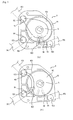
- FIG. 5 is a diagram illustrating an operation process of the passage switching device provided in the vacuum cleaner
- FIG. 6 includes a perspective view and an exploded perspective view illustrating a passage switching device according to another embodiment.
- FIG. 7 is a diagram illustrating an operation process of the passage switching device shown in FIG. 6 .
- a vacuum cleaner 100 shown in FIG. 1 may include a body (B) configured to generate a suction force by using a vacuum motor and a connection part (C) configured to transmit the suction force generated in the body (B) to a suction nozzle (N) to guide suction of dust and air.
- the suction nozzle (N) connected to an end of the connection part may suck dust and foreign matters scattered on a surface to vacuum-clean together with air.
- the connection part (C) may include an extendible pipe (C1) and a connection hose (C2). An end of the extendible pipe (C1) may be connected with the suction nozzle (N) and the other end may be connected with the connection hose (C2), to make the suction nozzle (N) in communication with the body (B).
- the extendible pipe (C1) may be able to be extended for user convenience.
- the suction nozzle (N) connected with the extendible pipe (C1) may be movable forward/rearward and rightward/leftward with respect to the surface to vacuum-clean during the cleaning. Because of that, the connection hose (C2) may be formed of a flexible member for the user to perform cleaning smoothly.
- the vacuum motor (11, see FIG. 2 ) may be provided in the body (B). When the vacuum motor 11 is driven, the suction force may be generated and the suction force of the vacuum motor may be transported to the suction nozzle (N) via the connection part (C).
- FIG. 2 illustrates an internal structure of the body composing the vacuum cleaner according to the embodiment.
- the body (B) may be provided a suction unit 1 configured to generate the suction force, a dust separation device 3 in communication with the suction unit 1 and a dust collection device 5 in communication with the dust separation device 3.
- the suction unit 1 may include a motor housing 13 and the vacuum motor 11 may be arranged in the motor housing.
- the motor housing 13 may be in communication with the dust separation device 3 via an inlet part 131 and a filter device 331, and air sucked by the vacuum motor may be exhausted outside the body (B) via an outlet part 133.
- the dust separation device 3 may be in communication with the vacuum motor 11, the connection part (C) and the dust collection device 5.
- the foreign matters scattered on the surface to vacuum-clean may be sucked into the dust separation device, in a status of being mixed with air, and the dust separation device 3 may separate dust from air by using a centrifugal force according to a dust separation function.
- the foreign matters such as dust may be moved to the dust collection device 5 and the air separated from the dust and foreign matters may be moved to the vacuum motor 11.
- the dust separation device 3 may include a suction pipe 31 connected with the connection hose (C1), an air outlet 33 configured to exhaust the air out of the mixture of the air and foreign matters sucked via the suction pipe 31, and a dust outlet 35 connected with the dust collection device 5 to move the foreign matters separated from the air to the dust collection device 5.
- the structure of the dust separation device 3 shown in FIG. 2 may be a dust separation structure using a cyclone theory. Any dust separation structures capable of separating foreign matters and air from mixture of air and foreign matters sucked outside the body may be applicable to the dust separation device 3.
- the dust collection device 5 may include a dust collection chamber 51 configured to store the foreign matters drawn from the dust separation device 3 and a dust inlet 53 configured to make the dust collection chamber 51 communicate with the dust outlet 35.
- a dust compression device 7 may be provided in the dust collection device 5 to reduce a volume of the collected foreign matters by compressing the dust collected in the dust collection chamber 51.
- the dust compression device 7 may be driven by a passage switching device 9 which will be described later.
- the dust compression device 7 may compress the foreign matters collected in the dust collection chamber 51 to an end of the dust collection chamber 51, in communication with the dust collection chamber 51 of the dust collection device 5.
- FIG. 3 illustrates the dust compression device 7 provided in a top end of the dust collection chamber 51.
- the dust compression device 7 may be demountable from the dust collection device 5 by a mounting/demounting device 71.
- a case 72 having an open bottom may be provided in a bottom of the mounting/demounting device 71.
- the case 72 may be cylindrical shape.
- a piston 73 may be provided in the case 72.
- the piston 73 may be expandable or contractible within the dust collection chamber 51 according to an air pressure provided from a guide pipe 931 which will be described later, or it may reciprocate within the dust collection chamber 51.
- a compression part passage connection part 711 connected with the guide pipe 931 may be provided in an upper end of the mounting/demounting device 71 and the compression part passage connection part 711 may be in communication with the piston 73, passing through the mounding/demounting device 71.
- the position of the compression part passage connection part 711 may be one of examples and the compression part passage connection part 711 may be located at any positions in the dust compression device 7 only if it enables the guide pipe 931 to be in communication with the piston 73 (see 711a).
- the piston 73 may have an expandable and contractible structure only if it is able to be extendible according to the air pressure provided from the guide pipe 931.
- the piston 73 may be bellows, telescopic cylinder and air bag structures.
- a press plate 75 may be provided in an end of the piston 73 to close the open bottom of the case 72 when the piston is contacted.
- the press plate 75 may have a predetermined appearance corresponding to a cross section of the dust collection device 51.
- FIG. 3 illustrates a disc-shaped press plate 75 provided in the cylindrical dust collection chamber 51.
- the passage switching device 9 may enable the dust compression device 7 to selectively communicate with either of a low pressure part having a lower pressure than a pressure inside the dust compression device 7 or with a high pressure part having a higher pressure than the pressure inside the dust compression device 7.
- the low pressure part may be any element of the vacuum cleaner only if they have a lower pressure than the pressure inside the dust compression device and the high pressure part may be any element only if they have a higher pressure than the pressure inside the dust compression device.
- the low pressure part may be configured to be the inlet part (131, see FIG. 2 ) of the vacuum motor (11, see FIG. 2 ) and the high pressure part may be an outer surface of the body or the outlet part (133, see FIG. 2 ) of the vacuum motor 11, for explanation convenience.
- the passage switching device 9 may be configured to enable the dust compression device 7 to communicate with an inlet part of the vacuum motor 11 or external air of the body (an outlet part of the vacuum motor 11) selectively.
- the piston 73 may be contracted.
- the piston 73 may be growing or expanded only to compress the foreign matters collected in the dust collection chamber.
- the passage switching device 9 may include a first connection port 93 connected with the compression part passage connection part 711 of the dust compression device 7 via the guide pipe 931, a low pressure part connection port 94 in communication with the inlet of the vacuum motor 11 and a high pressure part connection port 95 in communication with external air of the body (the outlet of the vacuum motor 11).
- the low pressure part connection port 94 may be connected with a low pressure part passage connection pipe 1311 provided in the inlet part 131 via a lower pressure part connection pipe 941 and the high pressure part connection port 95 may be connected with a high pressure part passage connection pipe 1331 provided in the outlet part 133 via a high pressure part connection pipe 951 (see FIG. 2 ).
- the inlet part 131 of the motor housing 13 and the outlet part 133 of the motor housing 13 the inlet part 131 has the lowest pressure. Meanwhile, among them, the outlet part 133 has the highest pressure.
- an internal space of the dust collection chamber 51 may have an intermediate value between the pressure of the inlet part 131 and the pressure of the outlet part 133.
- the passage switching device 9 communicates the piston 73 of the dust compression device 7 with the inlet part 131 (the low pressure part)
- the internal space of the dust collection chamber 51 may have a higher pressure than the pressure of the the inlet part 131 and the piston 73 may be contracted.
- the passage switching device 9 communicates the piston 73 of the dust compression device 7 with the outlet part 133
- the pressure possessed by the external air of the body (B) may be higher than the pressure possessed by the internal space of the dust compression device 7 and the piston 73 may compress the foreign matters collected in the dust collection chamber 51 (that is, the growing of the piston).
- the dust separation device 3 may be connected with the inlet part 131 of the vacuum motor 11 via the filter device 331 and with the dust inlet 53 of the dust collection chamber 51 via the dust outlet 35.
- the suction force of the vacuum motor 11 may be transmitted to the dust separation device 3 via the inlet part 131, the filter device 331 and the air outlet 33 in communication with the filter device 331.
- the suction force transmitted to the dust separation device 3 may be transmitted to the connection hose (C2), the extendible pipe (C1) and the suction nozzle (N) via the suction pipe 31. Because of that, the foreign matters scattered on the surface to vacuum-clean in a state of mixed with air may be drawn into the dust separation device 3 via the suction pipe 31.
- the air drawn via the suction pipe 31 may contain foreign matters and the air outlet 33 may exhaust only air to the motor housing 13 via the filter device 331 and the inlet part 131.
- the air drawn into the motor housing 13 may be exhausted outside the body (B) via the outlet part 133.
- the foreign matters separated from the air within the dust separation device 3 may be moved to the dust collection chamber 51 via the dust outlet 35 and the dust inlet 53.
- the foreign matters drawn into the dust collection chamber 51 may be compressed by the piston 73 of the dust compression device 7.
- the passage switching device 9 may communicate external air of the body (the high pressure part) with the piston 73.
- the press plate 75 may press the foreign matters collected in the dust collection chamber.
- the piston 73 may contracted to be located in the case 72.
- the vacuum cleaner according to the embodiment may have an effect of enabling compression storage of foreign matters within the dust collection chamber.
- FIG. 4 illustrates a passage switching device according to an embodiment provided in the vacuum cleaner
- FIG. 6 illustrates a passage switching device according to another embodiment. As follows, a detailed structure of the passage switching device provided in the vacuum cleaner will be described.
- the passage switching device 9 may include a housing 91 configured to define an exterior appearance thereof, a compression part connection port 93 provided in the housing 91 and in communication with the dust compression device 7, a low pressure part connection port 94 connected with the low pressure part, and a high pressure part connection port 95 connected with the high pressure part.
- the compression part connection port 93 may be connected with the compression part connection pipe 931 and the low pressure part connection port 94 may be connected with the low pressure part connection pipe 941.
- the high pressure part connection port 95 may be connected with the high pressure part connection pipe 951.
- a chamber 92 may be provided in the housing 91 to provide a proper space.
- the passage switching device 9 may include a compression part passage 921 configured to communicate the chamber 92 with the compression part connection port 93, a low pressure part passage 923 configured to communicate the chamber with the low pressure part connection port 94, and a high pressure part connection passage 925 configured to communicate the chamber 92 with the high pressure part connection port 95.
- a rotational member 96 coupled to a shaft (S) of a motor (M) provided outside the chamber may be further provided in the chamber 92 to open the low pressure part passage and the high pressure part passage selectively.
- a shaft passing hole (H) may be provided in a bottom surface of the chamber 92 to have the shaft of the motor (M) to pass there through.
- the rotational member 96 shown in FIG. 4(b) may be a rotational plate 961 coupled to the shaft (S) of the motor, with partitioning the internal space of the chamber into an upper space and a lower space.
- a hole-shaped passage opening part 963 passing through the rotational plate may be provided in the rotational plate 961 to communicate the upper and lower spaces of the chamber with each other.
- the compression part passage 921 may be located in the upper space of the chamber 92 and the low pressure part passage 923 and the high pressure part passage 925 may be located in the lower space of the chamber 92.
- a gap between the low pressure part passage 923 and the high pressure part passage 925 may be larger than the passage opening part 963. This is because either of the low pressure part and high pressure part passages 923 and 925 has to communicate with the compression part passage 921 selectively.
- a partitioning part 98 extended from the high pressure part passage 925 to contact with a lower surface of the rotational plate 961 may be further provided in the chamber 92.
- the partitioning part 98 may be a rib or wall that is arranged to cover the high pressure part passage 925 and the space in communication with the high pressure part passage 925.
- the partitioning part 98 may be employed to partition off the high pressure part passage 925 and the space in communication with the high pressure part passage 925 from the low pressure part passage 923 and the space in communication with the low pressure part passage 923.
- the partitioning part 98 may be in contact with the lower surface of the rotational plate 961. Because of that, it may be prevented that the air inside the high pressure part passage 925 and the space in communication with the high pressure part passage 925 is mixed with the air inside the low pressure part passage 923 and the space in communication with the low pressure part passage 923.
- An area of the space covered by the partitioning part 98 may be identical to an area of the passage opening part 963 or larger than an area of the passage opening part.
- FIG. 4(b) illustrates the partitioning part 98 formed in a shape corresponding to a shape of the passage opening part 963.
- the rotational plate 961 is rotated and the passage opening part 963 provided in the rotational plate 961 may open or close the space inside the partitioning part 98 connected with the high pressure part passage 925 based on a rotation angle of the rotational plate 961.
- the partitioning part 98 may contact with the lower surface of the rotational plate 961 and the high pressure part passage 925 may be closed.
- the low pressure part passage 923 may be in communication with the passage opening part 963 and the low pressure part passage 923 may be then in communication with the compression part passage 921.
- the low pressure part passage 923 may be closed by the rotational plate and the high pressure part passage 925 may be in communication with the compression part passage 921 provided in the upper space of the chamber.
- the low pressure part passage 923 may be in communication with the low pressure part passage connection pipe 1311 via the low pressure part connection port 94 and the lower pressure part connection pipe 941. Because of that, the compression part passage 921 provided in the upper space of the chamber 92 may be in communication with the vacuum motor 11 (i.e. the low pressure part thereof).
- the high pressure part passage 925 may be in communication with the high pressure part via the high pressure part connection port 95, the high pressure part connection pipe 951 and the high pressure part passage connection pipe (1331, see FIG. 2 ).
- the compression part passage 921 provided in the upper space of the chamber 92 may be in communication with the high pressure part.
- FIG. 4(b) only illustrates the partitioning part 98 extending from the high pressure part passage 925.
- the partitioning part 98 may be provided in only the low pressure part passage 923 or it may be provided in each of the high pressure part passage 925 and the low pressure part passage 923, only if the rotational plate is able to communicate the compression part passage 921 with the low pressure part passage 923 and the high pressure part passage 925, selectively.
- the communication time between the high pressure part passage 925 and the compression part passage 921 may be shorter than the communication time between the low pressure part passage 923 and the compression part passage 921. This may generate a following effect.
- the piston 73 When the piston 73 is in communication with the high pressure part passage 925 for a short time period, the piston 73 may be growing quickly.
- the press plate 75 connected with the piston 73 may compress the dust or foreign matters collected in the dust collection chamber, while applying a shock to the dust or foreign matters. Because of that, the foreign matters may be compressed more smoothly and efficiently.
- a first guide member 97 may be provided in the chamber 92 to guide the rotation of the rotational member 96, with supporting the rotational member 96.
- a cover 99 may be further provided on the rotational member 96 to cover the rotational member 96, with closing the chamber 92 airtight.
- the first guide member 97 may be a step projected from a proper area of an inner circumferential surface of chamber 92 toward a center of the chamber 92.
- a proper area of an outer circumferential surface of the rotational plate 961 may be supported by the first guide member 97.
- the cover 99 may be detachably provided on a top surface of the chamber 92 and it may close the chamber 92 and the rotational member 96 airtight.
- a second guide member 991 may be provided under the cover 99 to support the top surface of the rotational plate 961 and to guide the rotation of the rotational plate 961 with respect to the cover 99.
- the second guide member 991 may be employed to prevent the rotational plate 961 from being separated from the first guide member 97 during the driving of the motor (M).
- the second guide member 991 may be provided in contact with the top surface of the rotational plate 961. If it is concerned that the second guide member 991 interferes with the rotation of the rotational plate 961, the second guide member 991 may be spaced apart a proper distance from the top surface of the rotational plate 961.
- a passage communication recess 993 may be provided as shown in FIG. 4(b) such that the compression part passage 921 may not be closed by the second guide member 991.
- the second guide member 991 may be partially cut away to form the passage communication recess 993 and the passage communication recess 993 may be arranged at a proper position corresponding to the position of the compression part passage 921.
- the arrangement may enable the compression part passage 921 to communicate with the passage opening part 963.
- FIG. 5(a) illustrates that the passage switching device 9 communicates the dust compression device 7 with the high pressure part to enable the piston (73, see FIG. 3 ) to compress the foreign matters collected in the dust collection chamber 51.
- FIG. 5(b) illustrates that the passage switching device 9 communicates the dust compression device 7 with the low pressure part to contract the piston 73 that is grown to compress the foreign matters collected in the dust collection chamber 51.
- the control unit may rotate the shaft (S) of the motor (M) to enable the passage opening part 963 of the rotational plate 961 to open the space surrounded by the partitioning part 98.
- the low pressure part passage 923 in communication with the inner circumferential surface of the chamber 92 and the space in communication with the low pressure part passage 923 may be closed by the lower surface of the rotational plate 961 and the partitioning part 98. Because of that, the compression part passage 921 may be in communication with the high pressure part passage 925.
- the high pressure part passage 925 may be in communication with the outlet part 133 or the outside of the body (B) via the high pressure part connection port 95 and the high pressure part connection pipe 951.
- the compression part passage 921 may be in communication with the piston 73 of the dust compression device 7 via the compression part connection port 93 and the guide pipe 931.
- the pressure possessed by the internal space of the dust collection chamber 51 having the piston 73 provided therein may be lower than the pressure possessed by the atmosphere.
- the press plate 75 provided in the end of the piston 73 may move toward the foreign matters collected in the dust collection chamber 51 toward the end of the dust collection chamber 51. Because of that, the foreign matters collected in the dust collection chamber 51 may be compressed.
- control unit may control the motor (M) to rotate the passage opening part 963 toward the low pressure part passage 923 (see FIG. 5(b) )
- the high pressure part passage 925 may be closed by the lower surface of the rotational plate 961 and the compression part passage 921 may be then in communication with the low pressure part passage 923.
- the compression part passage 921 may be in communication with the piston 73 of the dust compression device 7 via the compression part connection port 93 and the guide pipe 931.
- the low pressure part passage 923 may be in communication with the low pressure part passage connection pipe 1311 connected with the inlet part 131 of the motor housing 13, via the low pressure part connection port 94 and the low pressure part connection pipe 941.
- the low pressure part passage connection pipe 1311 may be provided in the inlet part 131 of the motor housing 13 and the inlet part 131 may be the space where the air exhausted from the dust separation device 3 is sucked. Because of that, the pressure possessed by the inlet part 131 may be lower than the pressure possessed by the internal space of the dust collection chamber 51.
- the air inside the piston 73 that expanded the piston 73 may move to the vacuum motor 11 via the inlet part 131 and the piston 73 may perform contraction.
- FIG. 6 illustrates a passage switching device according to another embodiment that is provided in the vacuum cleaner described above. As follows, a structure possessed by a passage switching device 19 according to another embodiment will be described.
- the passage switching device 19 may include a housing 191 configured to define an exterior appearance thereof, a compression part connection port 193 provided in the housing 191, a low pressure part connection port 194 provided in the housing 191 and a high pressure part connection port 195 provided in the housing 191.
- the passage switching device 19 may include a chamber 192 configured to provide a proper space in the housing 191 as shown in FIG. 6(b) .
- the chamber 191 may be provided a compression part passage 1921 in communication with the compression part connection port 193, a low pressure part passage 1923 in communication with the low pressure part connection port 194 and a high pressure part passage 1925 in communication with the high pressure part connection port 195.
- the housing 191 may further include a cover 199 provided on an upper end of the chamber 192 to close an internal space of the chamber 92 airtight.
- the compression part passage 1921, the low pressure part passage 1923 and the high pressure part passage 1925, which are provided in an inner circumferential surface of the chamber 192, may be selectively opened and closed by a rotational member 196 rotatably provided in the chamber 192.
- the rotational member 196 may be coupled to a shaft (S) of a motor (M) provided outside the housing 191.
- a shaft passing hole (H) may be provided in a bottom surface of the chamber 192 to insertedly pass the shaft (S) of the motor (M) there through.
- the rotational member 196 may include a rotational plate 1961 coupled to the shaft of the motor, a flange 1962 provided along an outer circumferential surface of the rotational plate 1961 and a passage opening part 1963 provided in the flange 1962.
- the flange 1962 may be in contact with an inner circumferential surface of the chamber 192 provided in the housing 191. In case of a rotational plate provided in the cylindrical-shaped chamber 192 as shown in FIG. 6(b) , the flange 1962 may be vertically extended from an outer circumferential surface of the rotational plate 1961.
- the compression part passage 1921, the low pressure part passage 1923 and the high pressure part passage 1925 may have the same height with respect to the bottom surface of the chamber 192.
- the flange 1962 may be in contact with the inner circumferential surface of the chamber 192. Because of that, the passage opening part 1963 configured to open the low pressure part passage 1923 or the high pressure part passage 1925 selectively may be provided in the flange 1962.
- a passage communication recess 1964 may be provided in the flange 1962 to maintain an opening status of the compression part passage 1921.
- the passage communication recess 1964 may have various shapes only if it can maintain the open status of the compression part passage 1921 in the rotation of the rotational member 196.
- FIG. 6(b) illustrates the flange 1962 having an upper end partially stepped or bent to form a recess.
- a guide member 1965 may be further provided in the passage communication recess 1964.
- the guide member 1965 may guide a relative rotation of the rotational member 196 with respect to the cover 199.
- the guide member 1965 may be a projection extended from the passage communication recess 1964 toward the cover 199 and the guide member 1965 may be as high as the upper end of the flange 1962.
- the rotational member 196 may be supported by a lower surface of the cover 199 via the upper end of the flange 1962 and the upper end of the guide member 1965. Because of that, the rotational member 196 may be prevented from being separated even when it is rotated by the motor (M).
- FIG. 7(a) illustrates that the passage switching device 19 communicates the dust compression device 7 with the atmosphere to enable the piston (73, see FIG. 3 ) to compress foreign matters collected in the dust collection chamber 51.
- FIG. 7(b) illustrates that the passage switching device 19 communicates the dust compression device 7 with the vacuum motor 11 to contract the piston 73 having grown enough to compress the foreign matters collected in the dust collection chamber 51.
- the control unit may rotate the shaft (S) of the motor (M) and the passage opening part 1963 of the flange 1962 may open the high pressure part passage 1925.
- the low pressure part passage 1923 in communication with the inner circumferential surface of the chamber 192 may be closed by the flange 1962 and the compression part passage 1921 may be then in communication with the high pressure part passage 1925.
- the high pressure part passage 1925 may be in communication with the outlet part 133 via the high pressure part connection port 195 and the high pressure part connection pipe 1951.
- the compression part passage 1921 may be in communication with the piston 73 of the dust compression device 7 via the compression part connection port 193 and the guide pipe 1931.
- the pressure possessed by the dust collection chamber 51 having the piston 73 provided therein may be lower than the pressure possessed by the atmosphere. Because of that, when the compression part passage 1921 is in communication with the high pressure part passage 1925, the air inside the high pressure part may be supplied to the piston 73 and the piston 73 may be expanded or growing within the dust collection chamber 51.
- the press plate 75 provided in the end of the piston 73 may move the foreign matters collected in the dust collection chamber 51 toward a side of the dust collection chamber 51, only to compress the foreign matters collected in the dust collection chamber 51.
- the control unit (not shown) rotates the passage opening part 1963 toward the low pressure part passage 1923 by controlling the motor (M) (see FIG. 7(b) )
- the high pressure part passage 1925 may be closed by the flange 1962 and the compression part passage 1921 may be then in communication with the low pressure part passage 1923.
- the compression part passage 1921 may be in communication with the piston 73 of the dust compression device 7 via the compression part connection port 193 and the guide pipe 931.
- the low pressure part passage 1923 may be in communication with the low pressure part passage connection pipe 1311 connected with the inlet part 131, via the low pressure part connection port 194 and the low pressure part connection pipe 1941.
- the low pressure part connection pipe (1311, see FIG. 2 ) may be provided in the inlet part 131 and the inlet part 131 may be the space where the air separated from the dust in the dust separation device 3 is drawn.
- the pressure possessed by the low pressure part passage connection pipe 1311 may be lower than the pressure possessed by the dust collection chamber 51.
- the motor (M) may be controlled to enable the communication time between the high pressure part passage 1925 with the compression part passage 1921 to be shorter than the communication time between the low pressure part passage 1923 and the compression part passage 1921.
- the piston 73 may be growing or expanded quickly.
- the press plate 75 connected with the piston 73 may compress the foreign matters collected in the dust collection chamber 51, with applying a shock to the foreign matters and the foreign matters may be compressed more smoothly and more efficiently, compared with a case of growing the piston 73 slowly.
- control unit may control the rotation speed of the rotational plate for the open time of the high pressure part passage to be shorter than the open time of the low pressure part passage and the effect mentioned above may be realized.
- any reference in this specification to "one embodiment,” “an embodiment,” “example embodiment,” etc. means that a particular feature, structure, or characteristic described in connection with the embodiment is included in at least one embodiment of the invention.
- the appearances of such phrases in various places in the specification are not necessarily all referring to the same embodiment.
Landscapes
- Engineering & Computer Science (AREA)
- Mechanical Engineering (AREA)
- Filters For Electric Vacuum Cleaners (AREA)
Abstract
Description
- Embodiments may relate to a vacuum cleaner, more particularly, to a vacuum cleaner which is able to compress dusts sucked therein only to enhance user convenience.
- Generally, a vacuum cleaner is an electric appliance that filters dust, dirt and foreign matters together with air into a body provided therein, after sucking them by using a vacuum motor mounted in the body.
- Such a vacuum cleaner may be classified into a canister type having a suction nozzle in communication with the body via a connection pipe and an upright type having a suction nozzle integrally formed with the body as suction inlet.
- The canister type vacuum cleaner out of the two types may include a vacuum cleaner body having a vacuum motor configured to generate a suction force mounted therein, a suction nozzle configured to suck dust and foreign matters scattered on a surface to vacuum-clean by the suction force generated in the body, and a connection pipe configured to connect the body and the suction nozzle with each other.
- In other words, once an electric power is applied to the body, the vacuum motor may be driven and the suction force may be generated. The suction force enables the suction nozzle to suck therein the air containing dust and foreign matters scattered on the surface which will be cleaned.
- The air containing the dust and foreign matters may be drawn into the body via the connection pipe.
- The dust and foreign matters contained in the air sucked into the body may be separated within a dust separation device provided in the body by cyclone theory.
- After that, the separated dust and foreign matters may be collected in a dust collection device in communication with the dust separation device and the air having the dust and foreign matters separated there from may be exhausted outside the body.
- In the meanwhile, if the dust and foreign matters separated by the dust separation device are accumulating in the dust collection device, a user may detach the dust collection device from the body to throw away the dust and foreign matters.
- However, the accumulating dust and foreign matters might be scattered within the dust collection device because of a light weight and they might be scattered when the user throws them away after separating the dust collection device from the body.
- Accordingly, the embodiments may be directed to a vacuum cleaner. To solve the problems, an object of the embodiments may be to provide a vacuum cleaner which includes a dust compression device to compress foreign matters collected in a dust collection device provided therein.
- Another object of the embodiments may be to provide a vacuum cleaner which can compress the foreign matters collected in the dust collection device by using a difference between a pressure inside a vacuum motor and a pressure inside the dust compression device and a difference between a pressure of external air and a pressure inside the dust compression device.
- A further object of the embodiments may be to provide a vacuum cleaner which includes a passage switching device to make the inside of the dust compression device in communication with the vacuum motor or external air selectively.
- To achieve these objects and other advantages and in accordance with the purpose of the embodiments, as embodied and broadly described herein, a vacuum cleaner includes a body having a vacuum motor provided therein; a dust collection device provided in the body to collect dust; a dust compression device expandable or contractible selectively, to compress the dust collected in the dust collection device; a passage switching device configured to selectively communicate the dust compression device with a low pressure part having a lower pressure than a pressure of the dust collection device and a high pressure part having a higher pressure than a pressure of the dust collection device, wherein the passage switching device includes a chamber comprising a compression part passage in communication with the dust compression device; a low pressure part passage provided in the chamber, in communication with the low pressure part; a high pressure part passage provided in the chamber, in communication with the high pressure part; and a rotational member rotatably provided in the chamber, to communicate the compression part passage with either of the low pressure part passage and the high pressure part passage.
- According to the embodiment, there may be an effect of providing a vacuum cleaner including a dust compression device configured to compress foreign matters stored in a dust collection device.
- Furthermore, there may be another effect of providing a vacuum cleaner which can compress the foreign matters collected in the dust collection device by using a difference between a pressure inside a vacuum motor and a pressure inside the dust compression device and a difference between a pressure of external air and a pressure inside the dust compression device.
- A still further, there may be a further effect of providing a vacuum cleaner including a passage switching device to make the inside of the dust compression device in communication with a vacuum motor or external air selectively
- It is to be understood that both the foregoing general description and the following detailed description of the embodiments or arrangements are exemplary and explanatory and are intended to provide further explanation of the embodiments as claimed.
- Arrangements and embodiments may be described in detail with reference to the following drawings in which like reference numerals refer to like elements and wherein:
-
FIG. 1 is a perspective view illustrating a vacuum cleaner according to an embodiment; -
FIG. 2 is a diagram illustrating a body provided in the vacuum cleaner; -
FIG. 3 is a perspective view illustrating a connection status among a dust separation device, a dust compression device and a dust collection device that are provided in the vacuum cleaner; -
FIG. 4 includes a perspective view and an exploded perspective view illustrating a passage switching device provided in the vacuum cleaner; -
FIG. 5 is a diagram illustrating an operation process of the passage switching device provided in the vacuum cleaner; -
FIG. 6 includes a perspective view and an exploded perspective view illustrating a passage switching device according to another embodiment; and -
FIG. 7 is a diagram illustrating an operation process of the passage switching device shown inFIG. 6 . - As follows, exemplary embodiments will be described in detail in reference to the accompanying drawings.
- Reference may now be made in detail to specific embodiments, examples of which may be illustrated in the accompanying drawings. Wherever possible, same reference numbers may be used throughout the drawings to refer to the same or like parts.
- A
vacuum cleaner 100 shown inFIG. 1 may include a body (B) configured to generate a suction force by using a vacuum motor and a connection part (C) configured to transmit the suction force generated in the body (B) to a suction nozzle (N) to guide suction of dust and air. - In the meanwhile, the suction nozzle (N) connected to an end of the connection part may suck dust and foreign matters scattered on a surface to vacuum-clean together with air.
- The connection part (C) may include an extendible pipe (C1) and a connection hose (C2). An end of the extendible pipe (C1) may be connected with the suction nozzle (N) and the other end may be connected with the connection hose (C2), to make the suction nozzle (N) in communication with the body (B).
- In this body, the extendible pipe (C1) may be able to be extended for user convenience.
- In the meanwhile, the suction nozzle (N) connected with the extendible pipe (C1) may be movable forward/rearward and rightward/leftward with respect to the surface to vacuum-clean during the cleaning. Because of that, the connection hose (C2) may be formed of a flexible member for the user to perform cleaning smoothly.
- The vacuum motor (11, see
FIG. 2 ) may be provided in the body (B). When thevacuum motor 11 is driven, the suction force may be generated and the suction force of the vacuum motor may be transported to the suction nozzle (N) via the connection part (C). - As a result, dust and foreign matters existing on the surface to vacuum-clean may be sucked into the body (B) and the sucked foreign matters may be collected in a dust collection device provided in the body (B), which will be described in detail later.
-
FIG. 2 illustrates an internal structure of the body composing the vacuum cleaner according to the embodiment. In the body (B) may be provided asuction unit 1 configured to generate the suction force, adust separation device 3 in communication with thesuction unit 1 and adust collection device 5 in communication with thedust separation device 3. - The
suction unit 1 may include amotor housing 13 and thevacuum motor 11 may be arranged in the motor housing. - The
motor housing 13 may be in communication with thedust separation device 3 via aninlet part 131 and afilter device 331, and air sucked by the vacuum motor may be exhausted outside the body (B) via anoutlet part 133. - The
dust separation device 3 may be in communication with thevacuum motor 11, the connection part (C) and thedust collection device 5. The foreign matters scattered on the surface to vacuum-clean may be sucked into the dust separation device, in a status of being mixed with air, and thedust separation device 3 may separate dust from air by using a centrifugal force according to a dust separation function. - After that, the foreign matters such as dust may be moved to the
dust collection device 5 and the air separated from the dust and foreign matters may be moved to thevacuum motor 11. - The
dust separation device 3 may include asuction pipe 31 connected with the connection hose (C1), anair outlet 33 configured to exhaust the air out of the mixture of the air and foreign matters sucked via thesuction pipe 31, and adust outlet 35 connected with thedust collection device 5 to move the foreign matters separated from the air to thedust collection device 5. - The structure of the
dust separation device 3 shown inFIG. 2 may be a dust separation structure using a cyclone theory. Any dust separation structures capable of separating foreign matters and air from mixture of air and foreign matters sucked outside the body may be applicable to thedust separation device 3. - According to a structure of the dust collection device shown in
FIG. 3 , thedust collection device 5 may include adust collection chamber 51 configured to store the foreign matters drawn from thedust separation device 3 and adust inlet 53 configured to make thedust collection chamber 51 communicate with thedust outlet 35. - In the meanwhile, a
dust compression device 7 may be provided in thedust collection device 5 to reduce a volume of the collected foreign matters by compressing the dust collected in thedust collection chamber 51. - The
dust compression device 7 may be driven by apassage switching device 9 which will be described later. - As follows, the connection among the
dust separation device 3, thedust collection device 5, thedust compression device 7 and thepassage switching device 9 will be described. - The
dust compression device 7 may compress the foreign matters collected in thedust collection chamber 51 to an end of thedust collection chamber 51, in communication with thedust collection chamber 51 of thedust collection device 5. -
FIG. 3 illustrates thedust compression device 7 provided in a top end of thedust collection chamber 51. Thedust compression device 7 may be demountable from thedust collection device 5 by a mounting/demounting device 71. - A
case 72 having an open bottom may be provided in a bottom of the mounting/demounting device 71. Thecase 72 may be cylindrical shape. - A
piston 73 may be provided in thecase 72. Thepiston 73 may be expandable or contractible within thedust collection chamber 51 according to an air pressure provided from aguide pipe 931 which will be described later, or it may reciprocate within thedust collection chamber 51. - In the meanwhile, a compression part
passage connection part 711 connected with theguide pipe 931 may be provided in an upper end of the mounting/demounting device 71 and the compression partpassage connection part 711 may be in communication with thepiston 73, passing through the mounding/demounting device 71. - Here, the position of the compression part
passage connection part 711 may be one of examples and the compression partpassage connection part 711 may be located at any positions in thedust compression device 7 only if it enables theguide pipe 931 to be in communication with the piston 73 (see 711a). - The
piston 73 may have an expandable and contractible structure only if it is able to be extendible according to the air pressure provided from theguide pipe 931. Thepiston 73 may be bellows, telescopic cylinder and air bag structures. - A
press plate 75 may be provided in an end of thepiston 73 to close the open bottom of thecase 72 when the piston is contacted. - In this case, the
press plate 75 may have a predetermined appearance corresponding to a cross section of thedust collection device 51.FIG. 3 illustrates a disc-shapedpress plate 75 provided in the cylindricaldust collection chamber 51. - The
passage switching device 9 may enable thedust compression device 7 to selectively communicate with either of a low pressure part having a lower pressure than a pressure inside thedust compression device 7 or with a high pressure part having a higher pressure than the pressure inside thedust compression device 7. - The low pressure part may be any element of the vacuum cleaner only if they have a lower pressure than the pressure inside the dust compression device and the high pressure part may be any element only if they have a higher pressure than the pressure inside the dust compression device.
- As follows, the low pressure part may be configured to be the inlet part (131, see
FIG. 2 ) of the vacuum motor (11, seeFIG. 2 ) and the high pressure part may be an outer surface of the body or the outlet part (133, seeFIG. 2 ) of thevacuum motor 11, for explanation convenience. - The
passage switching device 9 may be configured to enable thedust compression device 7 to communicate with an inlet part of thevacuum motor 11 or external air of the body (an outlet part of the vacuum motor 11) selectively. When thedust compression device 7 is in communication with the inlet of thevacuum motor 11, thepiston 73 may be contracted. - However, when the
dust compression device 7 is in communication with the external air of the body (the outlet part of the vacuum motor 11), thepiston 73 may be growing or expanded only to compress the foreign matters collected in the dust collection chamber. - The
passage switching device 9 may include afirst connection port 93 connected with the compression partpassage connection part 711 of thedust compression device 7 via theguide pipe 931, a low pressurepart connection port 94 in communication with the inlet of thevacuum motor 11 and a high pressurepart connection port 95 in communication with external air of the body (the outlet of the vacuum motor 11). - The low pressure
part connection port 94 may be connected with a low pressure partpassage connection pipe 1311 provided in theinlet part 131 via a lower pressurepart connection pipe 941 and the high pressurepart connection port 95 may be connected with a high pressure partpassage connection pipe 1331 provided in theoutlet part 133 via a high pressure part connection pipe 951 (seeFIG. 2 ). - In the embodiment, among the
dust collection chamber 51, theinlet part 131 of themotor housing 13 and theoutlet part 133 of themotor housing 13, theinlet part 131 has the lowest pressure. Meanwhile, among them, theoutlet part 133 has the highest pressure. Here, an internal space of thedust collection chamber 51 may have an intermediate value between the pressure of theinlet part 131 and the pressure of theoutlet part 133. - As a result, when the
passage switching device 9 communicates thepiston 73 of thedust compression device 7 with the inlet part 131 (the low pressure part), the internal space of thedust collection chamber 51 may have a higher pressure than the pressure of the theinlet part 131 and thepiston 73 may be contracted. - However, when the
passage switching device 9 communicates thepiston 73 of thedust compression device 7 with theoutlet part 133, the pressure possessed by the external air of the body (B) may be higher than the pressure possessed by the internal space of thedust compression device 7 and thepiston 73 may compress the foreign matters collected in the dust collection chamber 51 (that is, the growing of the piston). - As follows, the process of collecting and compressing the foreign matters will be described in brief in reference to
FIGS. 2 and3 . - In reference to
FIG. 2 , thedust separation device 3 may be connected with theinlet part 131 of thevacuum motor 11 via thefilter device 331 and with thedust inlet 53 of thedust collection chamber 51 via thedust outlet 35. - As a result, when the
vacuum motor 11 is driven, the suction force of thevacuum motor 11 may be transmitted to thedust separation device 3 via theinlet part 131, thefilter device 331 and theair outlet 33 in communication with thefilter device 331. - The suction force transmitted to the
dust separation device 3 may be transmitted to the connection hose (C2), the extendible pipe (C1) and the suction nozzle (N) via thesuction pipe 31. Because of that, the foreign matters scattered on the surface to vacuum-clean in a state of mixed with air may be drawn into thedust separation device 3 via thesuction pipe 31. - The air drawn via the
suction pipe 31 may contain foreign matters and theair outlet 33 may exhaust only air to themotor housing 13 via thefilter device 331 and theinlet part 131. The air drawn into themotor housing 13 may be exhausted outside the body (B) via theoutlet part 133. - In the meanwhile, the foreign matters separated from the air within the
dust separation device 3 may be moved to thedust collection chamber 51 via thedust outlet 35 and thedust inlet 53. - In reference to
FIG. 3 , the foreign matters drawn into thedust collection chamber 51 may be compressed by thepiston 73 of thedust compression device 7. - In other words, the
passage switching device 9 may communicate external air of the body (the high pressure part) with thepiston 73. When the piston is growing after that, thepress plate 75 may press the foreign matters collected in the dust collection chamber. - However, when the
passage switching device 9 communicates thepiston 73 with the inlet part (the low pressure part) 131, thepiston 73 may contracted to be located in thecase 72. - As a result, the vacuum cleaner according to the embodiment may have an effect of enabling compression storage of foreign matters within the dust collection chamber.
-
FIG. 4 illustrates a passage switching device according to an embodiment provided in the vacuum cleaner andFIG. 6 illustrates a passage switching device according to another embodiment. As follows, a detailed structure of the passage switching device provided in the vacuum cleaner will be described. - First of all, a structure of a passage switching device disclosed in
FIG. 4 will be described. as shown inFIG. 4(a) , thepassage switching device 9 may include ahousing 91 configured to define an exterior appearance thereof, a compressionpart connection port 93 provided in thehousing 91 and in communication with thedust compression device 7, a low pressurepart connection port 94 connected with the low pressure part, and a high pressurepart connection port 95 connected with the high pressure part. - The compression
part connection port 93 may be connected with the compressionpart connection pipe 931 and the low pressurepart connection port 94 may be connected with the low pressurepart connection pipe 941. The high pressurepart connection port 95 may be connected with the high pressurepart connection pipe 951. - According to an internal structure of the
passage switching device 9 in reference toFIG. 4(b) , achamber 92 may be provided in thehousing 91 to provide a proper space. - Also, the
passage switching device 9 may include acompression part passage 921 configured to communicate thechamber 92 with the compressionpart connection port 93, a lowpressure part passage 923 configured to communicate the chamber with the low pressurepart connection port 94, and a high pressurepart connection passage 925 configured to communicate thechamber 92 with the high pressurepart connection port 95. - A
rotational member 96 coupled to a shaft (S) of a motor (M) provided outside the chamber may be further provided in thechamber 92 to open the low pressure part passage and the high pressure part passage selectively. - In this case, a shaft passing hole (H) may be provided in a bottom surface of the
chamber 92 to have the shaft of the motor (M) to pass there through. - The
rotational member 96 shown inFIG. 4(b) may be arotational plate 961 coupled to the shaft (S) of the motor, with partitioning the internal space of the chamber into an upper space and a lower space. - In this case, a hole-shaped
passage opening part 963 passing through the rotational plate may be provided in therotational plate 961 to communicate the upper and lower spaces of the chamber with each other. Thecompression part passage 921 may be located in the upper space of thechamber 92 and the lowpressure part passage 923 and the highpressure part passage 925 may be located in the lower space of thechamber 92. - A gap between the low
pressure part passage 923 and the highpressure part passage 925 may be larger than thepassage opening part 963. This is because either of the low pressure part and highpressure part passages compression part passage 921 selectively. - Here, a
partitioning part 98 extended from the highpressure part passage 925 to contact with a lower surface of therotational plate 961 may be further provided in thechamber 92. - The
partitioning part 98 may be a rib or wall that is arranged to cover the highpressure part passage 925 and the space in communication with the highpressure part passage 925. - The
partitioning part 98 may be employed to partition off the highpressure part passage 925 and the space in communication with the highpressure part passage 925 from the lowpressure part passage 923 and the space in communication with the lowpressure part passage 923. - The
partitioning part 98 may be in contact with the lower surface of therotational plate 961. Because of that, it may be prevented that the air inside the highpressure part passage 925 and the space in communication with the highpressure part passage 925 is mixed with the air inside the lowpressure part passage 923 and the space in communication with the lowpressure part passage 923. - An area of the space covered by the
partitioning part 98 may be identical to an area of thepassage opening part 963 or larger than an area of the passage opening part.FIG. 4(b) illustrates thepartitioning part 98 formed in a shape corresponding to a shape of thepassage opening part 963. - As a result, when the motor (M) is driven by a control unit (not shown), the
rotational plate 961 is rotated and thepassage opening part 963 provided in therotational plate 961 may open or close the space inside thepartitioning part 98 connected with the highpressure part passage 925 based on a rotation angle of therotational plate 961. - In other words, when the
passage opening part 963 of therotational plate 961 is located above the lowpressure part passage 923, thepartitioning part 98 may contact with the lower surface of therotational plate 961 and the highpressure part passage 925 may be closed. - In this case, the low
pressure part passage 923 may be in communication with thepassage opening part 963 and the lowpressure part passage 923 may be then in communication with thecompression part passage 921. - However, when the
passage opening part 963 of the rotational plate is located above the space surrounded by thepartitioning part 98, the lowpressure part passage 923 may be closed by the rotational plate and the highpressure part passage 925 may be in communication with thecompression part passage 921 provided in the upper space of the chamber. - When the space surrounded by the
partitioning part 98 is closed by therotational plate 961, the lowpressure part passage 923 may be in communication with the low pressure partpassage connection pipe 1311 via the low pressurepart connection port 94 and the lower pressurepart connection pipe 941. Because of that, thecompression part passage 921 provided in the upper space of thechamber 92 may be in communication with the vacuum motor 11 (i.e. the low pressure part thereof). - In the meanwhile, when the space surrounded by the
partitioning part 98 is opened by the rotational plate 961 (in other words, when thepassage opening part 963 is located above the partitioning part 98), the highpressure part passage 925 may be in communication with the high pressure part via the high pressurepart connection port 95, the high pressurepart connection pipe 951 and the high pressure part passage connection pipe (1331, seeFIG. 2 ). - As a result, the
compression part passage 921 provided in the upper space of thechamber 92 may be in communication with the high pressure part. -
FIG. 4(b) only illustrates thepartitioning part 98 extending from the highpressure part passage 925. Thepartitioning part 98 may be provided in only the lowpressure part passage 923 or it may be provided in each of the highpressure part passage 925 and the lowpressure part passage 923, only if the rotational plate is able to communicate thecompression part passage 921 with the lowpressure part passage 923 and the highpressure part passage 925, selectively. - Here, if the rotation speed of the
rotational plate 961 is uniform in case that thepartitioning part 98 is extended from the highpressure part passage 925, the communication time between the highpressure part passage 925 and thecompression part passage 921 may be shorter than the communication time between the lowpressure part passage 923 and thecompression part passage 921. This may generate a following effect. - When the
piston 73 is in communication with the highpressure part passage 925 for a short time period, thepiston 73 may be growing quickly. Here, thepress plate 75 connected with thepiston 73 may compress the dust or foreign matters collected in the dust collection chamber, while applying a shock to the dust or foreign matters. Because of that, the foreign matters may be compressed more smoothly and efficiently. - A
first guide member 97 may be provided in thechamber 92 to guide the rotation of therotational member 96, with supporting therotational member 96. Acover 99 may be further provided on therotational member 96 to cover therotational member 96, with closing thechamber 92 airtight. - The
first guide member 97 may be a step projected from a proper area of an inner circumferential surface ofchamber 92 toward a center of thechamber 92. - In this case, a proper area of an outer circumferential surface of the
rotational plate 961 may be supported by thefirst guide member 97. - The
cover 99 may be detachably provided on a top surface of thechamber 92 and it may close thechamber 92 and therotational member 96 airtight. - In the meanwhile, a
second guide member 991 may be provided under thecover 99 to support the top surface of therotational plate 961 and to guide the rotation of therotational plate 961 with respect to thecover 99. - The
second guide member 991 may be employed to prevent therotational plate 961 from being separated from thefirst guide member 97 during the driving of the motor (M). - As a result, the
second guide member 991 may be provided in contact with the top surface of therotational plate 961. If it is concerned that thesecond guide member 991 interferes with the rotation of therotational plate 961, thesecond guide member 991 may be spaced apart a proper distance from the top surface of therotational plate 961. - In the meanwhile, even if the
second guide member 991 is extended downwardly from thecover 99 to support the top surface of therotational plate 961, thecompression part passage 921 provided in thechamber 92 should not be closed by thesecond guide member 991. - In other words, if the
second guide member 991 is provided along a lower circumferential surface of the cover, apassage communication recess 993 may be provided as shown inFIG. 4(b) such that thecompression part passage 921 may not be closed by thesecond guide member 991. - The
second guide member 991 may be partially cut away to form thepassage communication recess 993 and thepassage communication recess 993 may be arranged at a proper position corresponding to the position of thecompression part passage 921. - The arrangement may enable the
compression part passage 921 to communicate with thepassage opening part 963. - As follows, an operation process of the
passage switching device 9 having the configuration described above will be described in reference toFIG. 5 . -
FIG. 5(a) illustrates that thepassage switching device 9 communicates thedust compression device 7 with the high pressure part to enable the piston (73, seeFIG. 3 ) to compress the foreign matters collected in thedust collection chamber 51. -
FIG. 5(b) illustrates that thepassage switching device 9 communicates thedust compression device 7 with the low pressure part to contract thepiston 73 that is grown to compress the foreign matters collected in thedust collection chamber 51. - First of all, it will be described the case of the
piston 73 compressing the foreign matters collected in thedust collection chamber 51. The control unit (not shown) may rotate the shaft (S) of the motor (M) to enable thepassage opening part 963 of therotational plate 961 to open the space surrounded by thepartitioning part 98. - In this case, the low
pressure part passage 923 in communication with the inner circumferential surface of thechamber 92 and the space in communication with the lowpressure part passage 923 may be closed by the lower surface of therotational plate 961 and thepartitioning part 98. Because of that, thecompression part passage 921 may be in communication with the highpressure part passage 925. - The high
pressure part passage 925 may be in communication with theoutlet part 133 or the outside of the body (B) via the high pressurepart connection port 95 and the high pressurepart connection pipe 951. Thecompression part passage 921 may be in communication with thepiston 73 of thedust compression device 7 via the compressionpart connection port 93 and theguide pipe 931. - In this case, the pressure possessed by the internal space of the
dust collection chamber 51 having thepiston 73 provided therein may be lower than the pressure possessed by the atmosphere. - As a result, when the
compression part passage 921 is in communication with the highpressure part passage 925, external air of the body (the atmosphere) or air of theoutlet part 133 may be supplied to thepiston 73 and thepiston 73 may be growing within thedust collection chamber 51. - When the
piston 73 is growing, thepress plate 75 provided in the end of thepiston 73 may move toward the foreign matters collected in thedust collection chamber 51 toward the end of thedust collection chamber 51. Because of that, the foreign matters collected in thedust collection chamber 51 may be compressed. - In the meanwhile, when the control unit (not shown) may control the motor (M) to rotate the
passage opening part 963 toward the low pressure part passage 923 (seeFIG. 5(b) ), the highpressure part passage 925 may be closed by the lower surface of therotational plate 961 and thecompression part passage 921 may be then in communication with the lowpressure part passage 923. - The
compression part passage 921 may be in communication with thepiston 73 of thedust compression device 7 via the compressionpart connection port 93 and theguide pipe 931. The lowpressure part passage 923 may be in communication with the low pressure partpassage connection pipe 1311 connected with theinlet part 131 of themotor housing 13, via the low pressurepart connection port 94 and the low pressurepart connection pipe 941. - The low pressure part
passage connection pipe 1311 may be provided in theinlet part 131 of themotor housing 13 and theinlet part 131 may be the space where the air exhausted from thedust separation device 3 is sucked. Because of that, the pressure possessed by theinlet part 131 may be lower than the pressure possessed by the internal space of thedust collection chamber 51. - As a result, the air inside the
piston 73 that expanded thepiston 73 may move to thevacuum motor 11 via theinlet part 131 and thepiston 73 may perform contraction. -
FIG. 6 illustrates a passage switching device according to another embodiment that is provided in the vacuum cleaner described above. As follows, a structure possessed by apassage switching device 19 according to another embodiment will be described. - The
passage switching device 19 according to this embodiment may include ahousing 191 configured to define an exterior appearance thereof, a compressionpart connection port 193 provided in thehousing 191, a low pressurepart connection port 194 provided in thehousing 191 and a high pressurepart connection port 195 provided in thehousing 191. - Here, the
passage switching device 19 may include achamber 192 configured to provide a proper space in thehousing 191 as shown inFIG. 6(b) . - The
chamber 191 may be provided acompression part passage 1921 in communication with the compressionpart connection port 193, a lowpressure part passage 1923 in communication with the low pressurepart connection port 194 and a highpressure part passage 1925 in communication with the high pressurepart connection port 195. - In this case, the
housing 191 may further include acover 199 provided on an upper end of thechamber 192 to close an internal space of thechamber 92 airtight. - The
compression part passage 1921, the lowpressure part passage 1923 and the highpressure part passage 1925, which are provided in an inner circumferential surface of thechamber 192, may be selectively opened and closed by arotational member 196 rotatably provided in thechamber 192. Therotational member 196 may be coupled to a shaft (S) of a motor (M) provided outside thehousing 191. - For that, a shaft passing hole (H) may be provided in a bottom surface of the
chamber 192 to insertedly pass the shaft (S) of the motor (M) there through. - The
rotational member 196 may include arotational plate 1961 coupled to the shaft of the motor, aflange 1962 provided along an outer circumferential surface of therotational plate 1961 and apassage opening part 1963 provided in theflange 1962. - The
flange 1962 may be in contact with an inner circumferential surface of thechamber 192 provided in thehousing 191. In case of a rotational plate provided in the cylindrical-shapedchamber 192 as shown inFIG. 6(b) , theflange 1962 may be vertically extended from an outer circumferential surface of therotational plate 1961. - In the
passage switching device 19 shown inFIG. 6 , thecompression part passage 1921, the lowpressure part passage 1923 and the highpressure part passage 1925 may have the same height with respect to the bottom surface of thechamber 192. - Also, the
flange 1962 may be in contact with the inner circumferential surface of thechamber 192. Because of that, thepassage opening part 1963 configured to open the lowpressure part passage 1923 or the highpressure part passage 1925 selectively may be provided in theflange 1962. - In the meanwhile, a
passage communication recess 1964 may be provided in theflange 1962 to maintain an opening status of thecompression part passage 1921. - The
passage communication recess 1964 may have various shapes only if it can maintain the open status of thecompression part passage 1921 in the rotation of therotational member 196.FIG. 6(b) illustrates theflange 1962 having an upper end partially stepped or bent to form a recess. - In this case, a
guide member 1965 may be further provided in thepassage communication recess 1964. Theguide member 1965 may guide a relative rotation of therotational member 196 with respect to thecover 199. - The
guide member 1965 may be a projection extended from thepassage communication recess 1964 toward thecover 199 and theguide member 1965 may be as high as the upper end of theflange 1962. - The
rotational member 196 may be supported by a lower surface of thecover 199 via the upper end of theflange 1962 and the upper end of theguide member 1965. Because of that, therotational member 196 may be prevented from being separated even when it is rotated by the motor (M). - As follows, an operation process of the passage switching device shown in
FIG. 6 will be described in reference toFIG. 7 . -
FIG. 7(a) illustrates that thepassage switching device 19 communicates thedust compression device 7 with the atmosphere to enable the piston (73, seeFIG. 3 ) to compress foreign matters collected in thedust collection chamber 51. -
FIG. 7(b) illustrates that thepassage switching device 19 communicates thedust compression device 7 with thevacuum motor 11 to contract thepiston 73 having grown enough to compress the foreign matters collected in thedust collection chamber 51. - First of all, the case of the
piston 73 compressing the foreign matters collected in thedust collection chamber 51 will be described. The control unit (not shown) may rotate the shaft (S) of the motor (M) and thepassage opening part 1963 of theflange 1962 may open the highpressure part passage 1925. - In this case, the low
pressure part passage 1923 in communication with the inner circumferential surface of thechamber 192 may be closed by theflange 1962 and thecompression part passage 1921 may be then in communication with the highpressure part passage 1925. - The high
pressure part passage 1925 may be in communication with theoutlet part 133 via the high pressurepart connection port 195 and the high pressure part connection pipe 1951. Thecompression part passage 1921 may be in communication with thepiston 73 of thedust compression device 7 via the compressionpart connection port 193 and the guide pipe 1931. - In the meanwhile, the pressure possessed by the
dust collection chamber 51 having thepiston 73 provided therein may be lower than the pressure possessed by the atmosphere. Because of that, when thecompression part passage 1921 is in communication with the highpressure part passage 1925, the air inside the high pressure part may be supplied to thepiston 73 and thepiston 73 may be expanded or growing within thedust collection chamber 51. - In this case, the
press plate 75 provided in the end of thepiston 73 may move the foreign matters collected in thedust collection chamber 51 toward a side of thedust collection chamber 51, only to compress the foreign matters collected in thedust collection chamber 51. - In the meanwhile, when the control unit (not shown) rotates the
passage opening part 1963 toward the lowpressure part passage 1923 by controlling the motor (M) (seeFIG. 7(b) ), the highpressure part passage 1925 may be closed by theflange 1962 and thecompression part passage 1921 may be then in communication with the lowpressure part passage 1923. - The
compression part passage 1921 may be in communication with thepiston 73 of thedust compression device 7 via the compressionpart connection port 193 and theguide pipe 931. The lowpressure part passage 1923 may be in communication with the low pressure partpassage connection pipe 1311 connected with theinlet part 131, via the low pressurepart connection port 194 and the low pressure part connection pipe 1941. - The low pressure part connection pipe (1311, see
FIG. 2 ) may be provided in theinlet part 131 and theinlet part 131 may be the space where the air separated from the dust in thedust separation device 3 is drawn. The pressure possessed by the low pressure partpassage connection pipe 1311 may be lower than the pressure possessed by thedust collection chamber 51. - As a result, when the
compression part passage 1921 is in communication with the lowpressure part passage 1923, the air supplied to thepiston 73 to grow thepiston 73 may move to thevacuum motor 11 via thesuction part 131. Because of that, thepiston 73 may be contracted. - In the mean while, the motor (M) may be controlled to enable the communication time between the high
pressure part passage 1925 with thecompression part passage 1921 to be shorter than the communication time between the lowpressure part passage 1923 and thecompression part passage 1921. - If the
piston 73 is in communication with the highpressure part passage 1925 in a short time period, thepiston 73 may be growing or expanded quickly. Here, thepress plate 75 connected with thepiston 73 may compress the foreign matters collected in thedust collection chamber 51, with applying a shock to the foreign matters and the foreign matters may be compressed more smoothly and more efficiently, compared with a case of growing thepiston 73 slowly. - Only if the
partitioning part 98 ofFig. 4 is provided in the highpressure part passage 1925 in case that therotational plate 1961 is rotated at a proper speed constantly by rotating the shaft of the motor at a proper speed constantly, the effect mentioned above may be realized. - However, if the rotation speed of the shaft of the motor is not maintained at a proper value, the control unit (not shown) may control the rotation speed of the rotational plate for the open time of the high pressure part passage to be shorter than the open time of the low pressure part passage and the effect mentioned above may be realized.
- Any reference in this specification to "one embodiment," "an embodiment," "example embodiment," etc., means that a particular feature, structure, or characteristic described in connection with the embodiment is included in at least one embodiment of the invention. The appearances of such phrases in various places in the specification are not necessarily all referring to the same embodiment. Further, when a particular feature, structure, or characteristic is described in connection with any embodiment, it is submitted that it is within the purview of one skilled in the art to affect such feature, structure, or characteristic in connection with other ones of the embodiments. Although embodiments have been described with reference to a number of illustrative embodiments thereof, it should be understood that numerous other modifications and embodiments can be devised by those skilled in the art that will fall within the spirit and scope of the principles of this disclosure. More particularly, various variations and modifications are possible in the component parts and/or arrangements of the subject combination arrangement within the scope of the disclosure, the drawings and the appended claims. In addition to variations and modifications in the component parts and/or arrangements, alternative uses will also be apparent to those skilled in the art.
Claims (15)
- A vacuum cleaner comprising:a body (B) having a vacuum motor (11) provided therein;a dust collection device (5) provided in the body (B) to collect dust;a dust compression device (7) expandable or contractible selectively, to compress the dust collected in the dust collection device (5);a passage switching device (9, 19) configured to selectively communicate the dust compression device (7) with a low pressure part having a lower pressure than a pressure of the dust collection device (5) and a high pressure part having a higher pressure than a pressure of the dust collection device (5),wherein the passage switching device (9, 19) comprises,a chamber (92, 192) comprising a compression part passage (921, 1921) in communication with the dust compression device (7);a low pressure part passage (923, 1923) provided in the chamber (92, 192), in communication with the low pressure part;a high pressure part passage (925, 1925) provided in the chamber (92, 192), in communication with the high pressure part; anda rotational member (96, 196) rotatably provided in the chamber (92, 192), to communicate the compression part passage (921, 1921) with either of the low pressure part passage (923, 1923) or the high pressure part passage (925, 1925).
- The vacuum cleaner of claim 1, further comprising:a passage opening part (963, 1963) provided in the rotational member (96, 196) to guide flow of air by opening the low pressure part passage (923, 1923) or the high pressure part passage (925, 1925) to communicate the low pressure part passage (923, 1923) or the high pressure part passage (925, 1925) with the compression part passage (921, 1921).
- The vacuum cleaner of claim 2, wherein the rotational member (96) is a circular rotational plate (961) to partition the chamber (92) into upper and lower spaces, and
the compression part passage (921) is provided in the upper space of the chamber (92) and the high pressure part passage (925) and the low pressure part passage (923) are provided in the lower space of the chamber (92). - The vacuum cleaner of claim 2, wherein an area of a space in the chamber (92, 192) in communication with the low pressure part passage (923, 1923) is larger than an area of a space in the chamber (92, 192) in communication with the high pressure part passage (925, 1925).
- The vacuum cleaner of claim 3, further comprising:a partitioning part (98) configured to surround the high pressure part passage (925) and a space in communication with the high pressure part passage (925) to partition them from the low pressure part passage (923) and a space in communication with the low pressure part passage (923),wherein the partitioning part (98) is in contact with the rotational plate (961), andan area of the space surrounded by the partitioning part (98) is identical to or larger than an area of the passage opening part (963).
- The vacuum cleaner of claim 2, further comprising:a first guide member (97) stepped in the chamber (92) to support a lower surface of the rotational plate (961) and to guide rotation of the rotational plate (961); anda cover (99),wherein the cover (99) comprises a second guide member (991) extended from the cover (99) downwardly to support a top surface of the rotational plate (961) and to guide rotation of the rotational plate (961).
- The vacuum cleaner of claim 2, further comprising:a cover (99, 199) detachably provided in an upper end of the chamber (92, 192) to cover the chamber (92, 192) and the rotational member (96, 196).
- The vacuum cleaner of claim 6, further comprising:a passage communication recess (993) provided in the cover (99) by cutting away the second guide member partially (991),wherein the passage communication recess (993) is arranged in a position, corresponding to the compression part passage (921), to communicate the passage opening part (963) with the compression part passage (921).
- The vacuum cleaner of claim 1, wherein the rotational member (196) comprises,
a circular-shaped rotational plate (1961);
a flange (1962) provided along an outer circumferential surface of the rotational plate (1961) to contact with an inner circumferential surface of the chamber (192), and
the passage opening part (1963) is provided in the flange (1962). - The vacuum cleaner of claim 9, further comprising:a passage communication recess (1964) provided in the flange (1962), which is separated from the passage opening part (1963), to communicate with the compression part passage (1921) constantly,wherein the passage communication recess (1964) is stepped from a predetermined area of the flange (1962).
- The vacuum cleaner of claim 10, further comprising:a cover (199) detachably provided in an upper end of the chamber (192) to cover the chamber (192) and the rotational member (196).
- The vacuum cleaner of claim 11, wherein the rotational member (196) further comprises,
a guide member (1965) provided in a side of the passage communication recess (1964), in contact with the cover (199), to guide rotation of the rotational member (196) with respect to the cover (199). - The vacuum cleaner of claim 1, wherein the low pressure part is an inlet (131) of the vacuum motor (11) or a space in communication with the inlet (131) of the vacuum motor (11),
wherein the high pressure part is an outlet (133) of the vacuum motor (11) or a space in communication with the outlet (133) of the vacuum motor (11), or the outside of the body (B). - The vacuum cleaner of claim 1, further comprising:a motor (M) provided outside the chamber (92, 192), which is connected with the rotational member (96, 196);a control unit configured to control a rotational direction and a rotational speed of a shaft (S) of the motor (M),wherein the control unit controls rotation of the rotational member (96, 196), for the communication time between the compression part passage (921, 1921) and the high pressure part passage (925, 1925) to be shorter than the communication time between the low pressure part passage (923, 1923) and the compression part passage (921, 1921).
- The vacuum cleaner of claim 1, wherein the dust compression device (7) is a piston (73) or a multi-way pipe having the size that is changeable based on change of the pressure possessed by air therein.
Applications Claiming Priority (1)
| Application Number | Priority Date | Filing Date | Title |
|---|---|---|---|
| KR1020100136277A KR101750310B1 (en) | 2010-12-28 | 2010-12-28 | Vacuum Cleaner |
Publications (3)
| Publication Number | Publication Date |
|---|---|
| EP2471428A2 true EP2471428A2 (en) | 2012-07-04 |
| EP2471428A3 EP2471428A3 (en) | 2013-10-30 |
| EP2471428B1 EP2471428B1 (en) | 2018-11-28 |
Family
ID=45444357
Family Applications (1)
| Application Number | Title | Priority Date | Filing Date |
|---|---|---|---|
| EP11010006.2A Not-in-force EP2471428B1 (en) | 2010-12-28 | 2011-12-20 | Vacuum cleaner with a dust compression device |
Country Status (3)
| Country | Link |
|---|---|
| US (1) | US8701244B2 (en) |
| EP (1) | EP2471428B1 (en) |
| KR (1) | KR101750310B1 (en) |
Families Citing this family (2)
| Publication number | Priority date | Publication date | Assignee | Title |
|---|---|---|---|---|
| CN107791128A (en) * | 2017-10-30 | 2018-03-13 | 重庆美艺轩木制品有限责任公司 | Timber sanding apparatus |
| DE102020102969A1 (en) | 2020-02-05 | 2021-08-05 | Vorwerk & Co. Interholding Gesellschaft mit beschränkter Haftung | vacuum cleaner |
Family Cites Families (12)
| Publication number | Priority date | Publication date | Assignee | Title |
|---|---|---|---|---|
| JPS5818091B2 (en) * | 1978-01-31 | 1983-04-11 | 東芝テック株式会社 | vacuum cleaner |
| NL220480A (en) * | 1978-10-19 | |||
| SE421171B (en) * | 1980-04-18 | 1981-12-07 | Electrolux Ab | DEVICE BY A LIFT CLEANER |
| JPS60185529A (en) | 1984-03-02 | 1985-09-21 | 松下電器産業株式会社 | vacuum cleaner |
| JP3004536B2 (en) | 1994-05-30 | 2000-01-31 | シャープ株式会社 | Electric vacuum cleaner |
| FR2823091B1 (en) | 2001-04-09 | 2003-06-13 | Seb Sa | DEVICE FOR COMPACTING WASTE IN A VACUUM |
| KR100595564B1 (en) * | 2004-07-16 | 2006-07-03 | 엘지전자 주식회사 | Vacuum cleaner |
| KR100869000B1 (en) * | 2004-12-14 | 2008-11-17 | 엘지전자 주식회사 | Dust compression method of vacuum cleaner and dust compression device of vacuum cleaner |
| KR100869003B1 (en) * | 2005-05-12 | 2008-11-17 | 엘지전자 주식회사 | Vacuum cleaner |
| US20080263815A1 (en) | 2007-04-30 | 2008-10-30 | Samsung Gwangju Electronics Co., Ltd. | Dust collecting apparatus for vacuum cleaner |
| US7611558B2 (en) | 2007-04-30 | 2009-11-03 | Samsung Gwangju Electronics Co., Ltd. | Dust compressing apparatus of vacuum cleaner |
| US8713752B2 (en) | 2009-03-13 | 2014-05-06 | Lg Electronics Inc. | Vacuum cleaner |
-
2010
- 2010-12-28 KR KR1020100136277A patent/KR101750310B1/en not_active Expired - Fee Related
-
2011
- 2011-11-22 US US13/301,985 patent/US8701244B2/en not_active Expired - Fee Related
- 2011-12-20 EP EP11010006.2A patent/EP2471428B1/en not_active Not-in-force
Non-Patent Citations (1)
| Title |
|---|
| None |
Also Published As
| Publication number | Publication date |
|---|---|
| US20120159737A1 (en) | 2012-06-28 |
| KR101750310B1 (en) | 2017-07-03 |
| US8701244B2 (en) | 2014-04-22 |
| EP2471428B1 (en) | 2018-11-28 |
| EP2471428A3 (en) | 2013-10-30 |
| KR20120074446A (en) | 2012-07-06 |
Similar Documents
| Publication | Publication Date | Title |
|---|---|---|
| KR101622726B1 (en) | Dust collector and vacuum cleaner having the same | |
| EP1674017B1 (en) | Dust collection unit and vacuum cleaner with the same | |
| US10849476B2 (en) | Vacuum cleaner | |
| EP1980327B1 (en) | Dust collector and vacuum cleaner | |
| EP1857032B1 (en) | Vacuum cleaner having primary and secondary cyclone units | |
| EP1929916B1 (en) | Vacuum cleaner | |
| US9668629B2 (en) | Vacuum cleaner | |
| KR20160138813A (en) | Dust collector for vacuum cleaner and vacuum cleaner having the same | |
| US8661611B2 (en) | Dust collector for a vacuum cleaner having a filtered dust removal function and vacuum cleaner | |
| EP2420173A1 (en) | Vacuum cleaner | |
| EP3809935B1 (en) | Cleaning appliance | |
| WO2015068817A1 (en) | Electric vacuum cleaner | |
| CN101073480B (en) | Vacuum cleaner | |
| CN1744843A (en) | Cyclone Separators for Vacuum Cleaners | |
| US8701244B2 (en) | Vacuum cleaner | |
| EP1676638A2 (en) | Apparatus for collecting dust and vacuum cleaner having the same | |
| JP2007268122A (en) | Electric vacuum cleaner | |
| CN103565362B (en) | Dust collect plant and possesses the electric dust collector of the dust collect plant | |
| US9186025B2 (en) | Upright type vacuum cleaner having dust compression device | |
| KR100842963B1 (en) | Vacuum cleaner | |
| EP3809934B1 (en) | Cleaning appliance | |
| JP6599596B2 (en) | Electric vacuum cleaner | |
| KR101750311B1 (en) | Vacuum Cleaner | |
| KR100854822B1 (en) | Vacuum cleaner | |
| JP2018140233A (en) | Vacuum cleaner |
Legal Events
| Date | Code | Title | Description |
|---|---|---|---|
| AK | Designated contracting states |
Kind code of ref document: A2 Designated state(s): AL AT BE BG CH CY CZ DE DK EE ES FI FR GB GR HR HU IE IS IT LI LT LU LV MC MK MT NL NO PL PT RO RS SE SI SK SM TR |
|
| AX | Request for extension of the european patent |
Extension state: BA ME |
|
| PUAI | Public reference made under article 153(3) epc to a published international application that has entered the european phase |
Free format text: ORIGINAL CODE: 0009012 |
|
| PUAL | Search report despatched |
Free format text: ORIGINAL CODE: 0009013 |
|
| AK | Designated contracting states |
Kind code of ref document: A3 Designated state(s): AL AT BE BG CH CY CZ DE DK EE ES FI FR GB GR HR HU IE IS IT LI LT LU LV MC MK MT NL NO PL PT RO RS SE SI SK SM TR |
|
| AX | Request for extension of the european patent |
Extension state: BA ME |
|
| RIC1 | Information provided on ipc code assigned before grant |
Ipc: A47L 9/10 20060101AFI20130926BHEP |
|
| 17P | Request for examination filed |
Effective date: 20140324 |
|
| RBV | Designated contracting states (corrected) |
Designated state(s): AL AT BE BG CH CY CZ DE DK EE ES FI FR GB GR HR HU IE IS IT LI LT LU LV MC MK MT NL NO PL PT RO RS SE SI SK SM TR |
|
| 17Q | First examination report despatched |
Effective date: 20160728 |
|
| GRAP | Despatch of communication of intention to grant a patent |
Free format text: ORIGINAL CODE: EPIDOSNIGR1 |
|
| INTG | Intention to grant announced |
Effective date: 20180618 |
|
| RAP1 | Party data changed (applicant data changed or rights of an application transferred) |
Owner name: LG ELECTRONICS INC. |
|
| GRAS | Grant fee paid |
Free format text: ORIGINAL CODE: EPIDOSNIGR3 |
|
| GRAA | (expected) grant |
Free format text: ORIGINAL CODE: 0009210 |
|
| AK | Designated contracting states |
Kind code of ref document: B1 Designated state(s): AL AT BE BG CH CY CZ DE DK EE ES FI FR GB GR HR HU IE IS IT LI LT LU LV MC MK MT NL NO PL PT RO RS SE SI SK SM TR |
|
| REG | Reference to a national code |
Ref country code: GB Ref legal event code: FG4D |
|
| REG | Reference to a national code |
Ref country code: CH Ref legal event code: EP |
|
| REG | Reference to a national code |
Ref country code: AT Ref legal event code: REF Ref document number: 1069249 Country of ref document: AT Kind code of ref document: T Effective date: 20181215 |
|
| REG | Reference to a national code |
Ref country code: DE Ref legal event code: R096 Ref document number: 602011054237 Country of ref document: DE |
|
| REG | Reference to a national code |
Ref country code: IE Ref legal event code: FG4D |
|
| REG | Reference to a national code |
Ref country code: NL Ref legal event code: MP Effective date: 20181128 |
|
| REG | Reference to a national code |
Ref country code: LT Ref legal event code: MG4D |
|
| REG | Reference to a national code |
Ref country code: AT Ref legal event code: MK05 Ref document number: 1069249 Country of ref document: AT Kind code of ref document: T Effective date: 20181128 |
|
| PG25 | Lapsed in a contracting state [announced via postgrant information from national office to epo] |
Ref country code: LV Free format text: LAPSE BECAUSE OF FAILURE TO SUBMIT A TRANSLATION OF THE DESCRIPTION OR TO PAY THE FEE WITHIN THE PRESCRIBED TIME-LIMIT Effective date: 20181128 Ref country code: FI Free format text: LAPSE BECAUSE OF FAILURE TO SUBMIT A TRANSLATION OF THE DESCRIPTION OR TO PAY THE FEE WITHIN THE PRESCRIBED TIME-LIMIT Effective date: 20181128 Ref country code: NO Free format text: LAPSE BECAUSE OF FAILURE TO SUBMIT A TRANSLATION OF THE DESCRIPTION OR TO PAY THE FEE WITHIN THE PRESCRIBED TIME-LIMIT Effective date: 20190228 Ref country code: LT Free format text: LAPSE BECAUSE OF FAILURE TO SUBMIT A TRANSLATION OF THE DESCRIPTION OR TO PAY THE FEE WITHIN THE PRESCRIBED TIME-LIMIT Effective date: 20181128 Ref country code: HR Free format text: LAPSE BECAUSE OF FAILURE TO SUBMIT A TRANSLATION OF THE DESCRIPTION OR TO PAY THE FEE WITHIN THE PRESCRIBED TIME-LIMIT Effective date: 20181128 Ref country code: BG Free format text: LAPSE BECAUSE OF FAILURE TO SUBMIT A TRANSLATION OF THE DESCRIPTION OR TO PAY THE FEE WITHIN THE PRESCRIBED TIME-LIMIT Effective date: 20190228 Ref country code: AT Free format text: LAPSE BECAUSE OF FAILURE TO SUBMIT A TRANSLATION OF THE DESCRIPTION OR TO PAY THE FEE WITHIN THE PRESCRIBED TIME-LIMIT Effective date: 20181128 Ref country code: ES Free format text: LAPSE BECAUSE OF FAILURE TO SUBMIT A TRANSLATION OF THE DESCRIPTION OR TO PAY THE FEE WITHIN THE PRESCRIBED TIME-LIMIT Effective date: 20181128 Ref country code: IS Free format text: LAPSE BECAUSE OF FAILURE TO SUBMIT A TRANSLATION OF THE DESCRIPTION OR TO PAY THE FEE WITHIN THE PRESCRIBED TIME-LIMIT Effective date: 20190328 |
|
| PG25 | Lapsed in a contracting state [announced via postgrant information from national office to epo] |
Ref country code: RS Free format text: LAPSE BECAUSE OF FAILURE TO SUBMIT A TRANSLATION OF THE DESCRIPTION OR TO PAY THE FEE WITHIN THE PRESCRIBED TIME-LIMIT Effective date: 20181128 Ref country code: PT Free format text: LAPSE BECAUSE OF FAILURE TO SUBMIT A TRANSLATION OF THE DESCRIPTION OR TO PAY THE FEE WITHIN THE PRESCRIBED TIME-LIMIT Effective date: 20190328 Ref country code: GR Free format text: LAPSE BECAUSE OF FAILURE TO SUBMIT A TRANSLATION OF THE DESCRIPTION OR TO PAY THE FEE WITHIN THE PRESCRIBED TIME-LIMIT Effective date: 20190301 Ref country code: AL Free format text: LAPSE BECAUSE OF FAILURE TO SUBMIT A TRANSLATION OF THE DESCRIPTION OR TO PAY THE FEE WITHIN THE PRESCRIBED TIME-LIMIT Effective date: 20181128 Ref country code: SE Free format text: LAPSE BECAUSE OF FAILURE TO SUBMIT A TRANSLATION OF THE DESCRIPTION OR TO PAY THE FEE WITHIN THE PRESCRIBED TIME-LIMIT Effective date: 20181128 |
|
| PG25 | Lapsed in a contracting state [announced via postgrant information from national office to epo] |
Ref country code: NL Free format text: LAPSE BECAUSE OF FAILURE TO SUBMIT A TRANSLATION OF THE DESCRIPTION OR TO PAY THE FEE WITHIN THE PRESCRIBED TIME-LIMIT Effective date: 20181128 |
|
| PG25 | Lapsed in a contracting state [announced via postgrant information from national office to epo] |
Ref country code: IT Free format text: LAPSE BECAUSE OF FAILURE TO SUBMIT A TRANSLATION OF THE DESCRIPTION OR TO PAY THE FEE WITHIN THE PRESCRIBED TIME-LIMIT Effective date: 20181128 Ref country code: CZ Free format text: LAPSE BECAUSE OF FAILURE TO SUBMIT A TRANSLATION OF THE DESCRIPTION OR TO PAY THE FEE WITHIN THE PRESCRIBED TIME-LIMIT Effective date: 20181128 Ref country code: PL Free format text: LAPSE BECAUSE OF FAILURE TO SUBMIT A TRANSLATION OF THE DESCRIPTION OR TO PAY THE FEE WITHIN THE PRESCRIBED TIME-LIMIT Effective date: 20181128 Ref country code: DK Free format text: LAPSE BECAUSE OF FAILURE TO SUBMIT A TRANSLATION OF THE DESCRIPTION OR TO PAY THE FEE WITHIN THE PRESCRIBED TIME-LIMIT Effective date: 20181128 |
|
| REG | Reference to a national code |
Ref country code: CH Ref legal event code: PL |
|
| REG | Reference to a national code |
Ref country code: DE Ref legal event code: R097 Ref document number: 602011054237 Country of ref document: DE |
|
| PG25 | Lapsed in a contracting state [announced via postgrant information from national office to epo] |
Ref country code: EE Free format text: LAPSE BECAUSE OF FAILURE TO SUBMIT A TRANSLATION OF THE DESCRIPTION OR TO PAY THE FEE WITHIN THE PRESCRIBED TIME-LIMIT Effective date: 20181128 Ref country code: SM Free format text: LAPSE BECAUSE OF FAILURE TO SUBMIT A TRANSLATION OF THE DESCRIPTION OR TO PAY THE FEE WITHIN THE PRESCRIBED TIME-LIMIT Effective date: 20181128 Ref country code: LU Free format text: LAPSE BECAUSE OF NON-PAYMENT OF DUE FEES Effective date: 20181220 Ref country code: SK Free format text: LAPSE BECAUSE OF FAILURE TO SUBMIT A TRANSLATION OF THE DESCRIPTION OR TO PAY THE FEE WITHIN THE PRESCRIBED TIME-LIMIT Effective date: 20181128 Ref country code: MC Free format text: LAPSE BECAUSE OF FAILURE TO SUBMIT A TRANSLATION OF THE DESCRIPTION OR TO PAY THE FEE WITHIN THE PRESCRIBED TIME-LIMIT Effective date: 20181128 Ref country code: RO Free format text: LAPSE BECAUSE OF FAILURE TO SUBMIT A TRANSLATION OF THE DESCRIPTION OR TO PAY THE FEE WITHIN THE PRESCRIBED TIME-LIMIT Effective date: 20181128 |
|
| REG | Reference to a national code |
Ref country code: IE Ref legal event code: MM4A |
|
| REG | Reference to a national code |
Ref country code: BE Ref legal event code: MM Effective date: 20181231 |
|
| PLBE | No opposition filed within time limit |
Free format text: ORIGINAL CODE: 0009261 |
|
| STAA | Information on the status of an ep patent application or granted ep patent |
Free format text: STATUS: NO OPPOSITION FILED WITHIN TIME LIMIT |
|
| PG25 | Lapsed in a contracting state [announced via postgrant information from national office to epo] |
Ref country code: FR Free format text: LAPSE BECAUSE OF NON-PAYMENT OF DUE FEES Effective date: 20190128 Ref country code: SI Free format text: LAPSE BECAUSE OF FAILURE TO SUBMIT A TRANSLATION OF THE DESCRIPTION OR TO PAY THE FEE WITHIN THE PRESCRIBED TIME-LIMIT Effective date: 20181128 Ref country code: IE Free format text: LAPSE BECAUSE OF NON-PAYMENT OF DUE FEES Effective date: 20181220 |
|
| 26N | No opposition filed |
Effective date: 20190829 |
|
| PG25 | Lapsed in a contracting state [announced via postgrant information from national office to epo] |
Ref country code: BE Free format text: LAPSE BECAUSE OF NON-PAYMENT OF DUE FEES Effective date: 20181231 |
|
| PG25 | Lapsed in a contracting state [announced via postgrant information from national office to epo] |
Ref country code: LI Free format text: LAPSE BECAUSE OF NON-PAYMENT OF DUE FEES Effective date: 20181231 Ref country code: CH Free format text: LAPSE BECAUSE OF NON-PAYMENT OF DUE FEES Effective date: 20181231 |
|
| PG25 | Lapsed in a contracting state [announced via postgrant information from national office to epo] |
Ref country code: MT Free format text: LAPSE BECAUSE OF NON-PAYMENT OF DUE FEES Effective date: 20181220 |
|
| PGFP | Annual fee paid to national office [announced via postgrant information from national office to epo] |
Ref country code: DE Payment date: 20191105 Year of fee payment: 9 |
|
| PG25 | Lapsed in a contracting state [announced via postgrant information from national office to epo] |
Ref country code: TR Free format text: LAPSE BECAUSE OF FAILURE TO SUBMIT A TRANSLATION OF THE DESCRIPTION OR TO PAY THE FEE WITHIN THE PRESCRIBED TIME-LIMIT Effective date: 20181128 |
|
| PGFP | Annual fee paid to national office [announced via postgrant information from national office to epo] |
Ref country code: GB Payment date: 20191106 Year of fee payment: 9 |
|
| PG25 | Lapsed in a contracting state [announced via postgrant information from national office to epo] |
Ref country code: MK Free format text: LAPSE BECAUSE OF NON-PAYMENT OF DUE FEES Effective date: 20181128 Ref country code: CY Free format text: LAPSE BECAUSE OF FAILURE TO SUBMIT A TRANSLATION OF THE DESCRIPTION OR TO PAY THE FEE WITHIN THE PRESCRIBED TIME-LIMIT Effective date: 20181128 Ref country code: HU Free format text: LAPSE BECAUSE OF FAILURE TO SUBMIT A TRANSLATION OF THE DESCRIPTION OR TO PAY THE FEE WITHIN THE PRESCRIBED TIME-LIMIT; INVALID AB INITIO Effective date: 20111220 |
|
| REG | Reference to a national code |
Ref country code: DE Ref legal event code: R119 Ref document number: 602011054237 Country of ref document: DE |
|
| GBPC | Gb: european patent ceased through non-payment of renewal fee |
Effective date: 20201220 |
|
| PG25 | Lapsed in a contracting state [announced via postgrant information from national office to epo] |
Ref country code: GB Free format text: LAPSE BECAUSE OF NON-PAYMENT OF DUE FEES Effective date: 20201220 Ref country code: DE Free format text: LAPSE BECAUSE OF NON-PAYMENT OF DUE FEES Effective date: 20210701 |