EP2470811B1 - Engine braking primary clutch for cvt systems - Google Patents
Engine braking primary clutch for cvt systems Download PDFInfo
- Publication number
- EP2470811B1 EP2470811B1 EP10823820.5A EP10823820A EP2470811B1 EP 2470811 B1 EP2470811 B1 EP 2470811B1 EP 10823820 A EP10823820 A EP 10823820A EP 2470811 B1 EP2470811 B1 EP 2470811B1
- Authority
- EP
- European Patent Office
- Prior art keywords
- sheave portion
- coupler
- ramp
- owc
- sheave
- Prior art date
- Legal status (The legal status is an assumption and is not a legal conclusion. Google has not performed a legal analysis and makes no representation as to the accuracy of the status listed.)
- Not-in-force
Links
Images







Classifications
-
- F—MECHANICAL ENGINEERING; LIGHTING; HEATING; WEAPONS; BLASTING
- F16—ENGINEERING ELEMENTS AND UNITS; GENERAL MEASURES FOR PRODUCING AND MAINTAINING EFFECTIVE FUNCTIONING OF MACHINES OR INSTALLATIONS; THERMAL INSULATION IN GENERAL
- F16H—GEARING
- F16H55/00—Elements with teeth or friction surfaces for conveying motion; Worms, pulleys or sheaves for gearing mechanisms
- F16H55/32—Friction members
- F16H55/52—Pulleys or friction discs of adjustable construction
- F16H55/56—Pulleys or friction discs of adjustable construction of which the bearing parts are relatively axially adjustable
-
- F—MECHANICAL ENGINEERING; LIGHTING; HEATING; WEAPONS; BLASTING
- F16—ENGINEERING ELEMENTS AND UNITS; GENERAL MEASURES FOR PRODUCING AND MAINTAINING EFFECTIVE FUNCTIONING OF MACHINES OR INSTALLATIONS; THERMAL INSULATION IN GENERAL
- F16H—GEARING
- F16H63/00—Control outputs from the control unit to change-speed- or reversing-gearings for conveying rotary motion or to other devices than the final output mechanism
- F16H63/02—Final output mechanisms therefor; Actuating means for the final output mechanisms
- F16H63/04—Final output mechanisms therefor; Actuating means for the final output mechanisms a single final output mechanism being moved by a single final actuating mechanism
- F16H63/06—Final output mechanisms therefor; Actuating means for the final output mechanisms a single final output mechanism being moved by a single final actuating mechanism the final output mechanism having an indefinite number of positions
- F16H63/067—Final output mechanisms therefor; Actuating means for the final output mechanisms a single final output mechanism being moved by a single final actuating mechanism the final output mechanism having an indefinite number of positions mechanical actuating means
-
- F—MECHANICAL ENGINEERING; LIGHTING; HEATING; WEAPONS; BLASTING
- F16—ENGINEERING ELEMENTS AND UNITS; GENERAL MEASURES FOR PRODUCING AND MAINTAINING EFFECTIVE FUNCTIONING OF MACHINES OR INSTALLATIONS; THERMAL INSULATION IN GENERAL
- F16H—GEARING
- F16H9/00—Gearings for conveying rotary motion with variable gear ratio, or for reversing rotary motion, by endless flexible members
- F16H9/02—Gearings for conveying rotary motion with variable gear ratio, or for reversing rotary motion, by endless flexible members without members having orbital motion
- F16H9/04—Gearings for conveying rotary motion with variable gear ratio, or for reversing rotary motion, by endless flexible members without members having orbital motion using belts, V-belts, or ropes
- F16H9/12—Gearings for conveying rotary motion with variable gear ratio, or for reversing rotary motion, by endless flexible members without members having orbital motion using belts, V-belts, or ropes engaging a pulley built-up out of relatively axially-adjustable parts in which the belt engages the opposite flanges of the pulley directly without interposed belt-supporting members
- F16H9/16—Gearings for conveying rotary motion with variable gear ratio, or for reversing rotary motion, by endless flexible members without members having orbital motion using belts, V-belts, or ropes engaging a pulley built-up out of relatively axially-adjustable parts in which the belt engages the opposite flanges of the pulley directly without interposed belt-supporting members using two pulleys, both built-up out of adjustable conical parts
- F16H9/18—Gearings for conveying rotary motion with variable gear ratio, or for reversing rotary motion, by endless flexible members without members having orbital motion using belts, V-belts, or ropes engaging a pulley built-up out of relatively axially-adjustable parts in which the belt engages the opposite flanges of the pulley directly without interposed belt-supporting members using two pulleys, both built-up out of adjustable conical parts only one flange of each pulley being adjustable
-
- F—MECHANICAL ENGINEERING; LIGHTING; HEATING; WEAPONS; BLASTING
- F16—ENGINEERING ELEMENTS AND UNITS; GENERAL MEASURES FOR PRODUCING AND MAINTAINING EFFECTIVE FUNCTIONING OF MACHINES OR INSTALLATIONS; THERMAL INSULATION IN GENERAL
- F16H—GEARING
- F16H59/00—Control inputs to control units of change-speed- or reversing-gearings for conveying rotary motion
- F16H59/14—Inputs being a function of torque or torque demand
- F16H59/18—Inputs being a function of torque or torque demand dependent on the position of the accelerator pedal
- F16H2059/186—Coasting
-
- F—MECHANICAL ENGINEERING; LIGHTING; HEATING; WEAPONS; BLASTING
- F16—ENGINEERING ELEMENTS AND UNITS; GENERAL MEASURES FOR PRODUCING AND MAINTAINING EFFECTIVE FUNCTIONING OF MACHINES OR INSTALLATIONS; THERMAL INSULATION IN GENERAL
- F16H—GEARING
- F16H55/00—Elements with teeth or friction surfaces for conveying motion; Worms, pulleys or sheaves for gearing mechanisms
- F16H55/32—Friction members
- F16H55/52—Pulleys or friction discs of adjustable construction
- F16H55/56—Pulleys or friction discs of adjustable construction of which the bearing parts are relatively axially adjustable
- F16H55/563—Pulleys or friction discs of adjustable construction of which the bearing parts are relatively axially adjustable actuated by centrifugal masses
-
- F—MECHANICAL ENGINEERING; LIGHTING; HEATING; WEAPONS; BLASTING
- F16—ENGINEERING ELEMENTS AND UNITS; GENERAL MEASURES FOR PRODUCING AND MAINTAINING EFFECTIVE FUNCTIONING OF MACHINES OR INSTALLATIONS; THERMAL INSULATION IN GENERAL
- F16H—GEARING
- F16H61/00—Control functions within control units of change-speed- or reversing-gearings for conveying rotary motion ; Control of exclusively fluid gearing, friction gearing, gearings with endless flexible members or other particular types of gearing
- F16H61/21—Providing engine brake control
-
- F—MECHANICAL ENGINEERING; LIGHTING; HEATING; WEAPONS; BLASTING
- F16—ENGINEERING ELEMENTS AND UNITS; GENERAL MEASURES FOR PRODUCING AND MAINTAINING EFFECTIVE FUNCTIONING OF MACHINES OR INSTALLATIONS; THERMAL INSULATION IN GENERAL
- F16H—GEARING
- F16H61/00—Control functions within control units of change-speed- or reversing-gearings for conveying rotary motion ; Control of exclusively fluid gearing, friction gearing, gearings with endless flexible members or other particular types of gearing
- F16H61/66—Control functions within control units of change-speed- or reversing-gearings for conveying rotary motion ; Control of exclusively fluid gearing, friction gearing, gearings with endless flexible members or other particular types of gearing specially adapted for continuously variable gearings
- F16H61/662—Control functions within control units of change-speed- or reversing-gearings for conveying rotary motion ; Control of exclusively fluid gearing, friction gearing, gearings with endless flexible members or other particular types of gearing specially adapted for continuously variable gearings with endless flexible members
- F16H61/66272—Control functions within control units of change-speed- or reversing-gearings for conveying rotary motion ; Control of exclusively fluid gearing, friction gearing, gearings with endless flexible members or other particular types of gearing specially adapted for continuously variable gearings with endless flexible members characterised by means for controlling the torque transmitting capability of the gearing
Definitions
- Continuously variable transmission (CVT) systems are used in vehicles to change transmission ratios between an engine output and a drive train of the vehicle.
- a primary clutch is coupled to receive a rotational output from an engine and a secondary clutch is coupled to provide a rotational output to the drive train.
- the primary clutch is coupled to provide rotation to the secondary clutch with an endless loop drive belt.
- typically the primary clutch is comprised of first and second conical-faced sheave portions that are configured in a way to move the second conical-faced sheave portion axially in relation to the first conical-faced sheave portion along an axis of rotation.
- the distance between the sheaves of the primary clutch determines the positioning of the drive belt in relation to the rotational axis and hence the transmission ratio.
- the closer the first and second sheave portions are positioned together the farther the drive belt is pinched on the conical-faces away from the rotational axis of the primary clutch.
- the farther the first and second sheave portions are positioned away from each other the closer the drive belt is the rotational axis of the primary clutch.
- the first and second sheaves of the primary clutch are axially positioned at a select distance from each other so at least one of the conical faced sheave portions does not engage a side of the drive belt. In this situation, the limited friction between the drive belt and the primary clutch allows the belt to slip so no rotational force is applied to the secondary sheave and hence no power is provided to the drive train by the engine.
- Engine braking is a term used to describe when the engine of a vehicle is used to provide at least some of the braking for the vehicle.
- An example situation where engine braking is beneficial occurs when a vehicle is going down a steep incline and the operator cuts back on the throttle. In this situation the engine's rotational output will be slower than the rotation of the drive train.
- the slow rotation of the engine is used to slow down the rotation of the drive train.
- the drive belt on a typical CVT system is designed to slip on the primary clutch during idle speeds of the motor, the engine effectively is disconnected from the drive train. This disconnection between the engine and the drive train prevents a typical CVT system from implementing engine braking. In this situation, other traditional braking means must be employed which may or may not be effective in a given situation.
- US-A-2002/0033295 discloses an all-terrain vehicle having a frame with front, rear, right, and left sides.
- the all-terrain vehicle includes an engine with at least one cylinder having an axis that defines an engine centreline.
- the all-terrain vehicle also includes an output shaft defining an output shaft centreline.
- a continuously variable transmission (“CVT”) operatively connects the engine to the output shaft and defines a CVT centreline.
- CVT continuously variable transmission
- a mechanism to permit free wheel operation is included.
- the CVT incorporates a slide sleeve on the drive pulley.
- the slide sleeve cooperates with one or more spring loaded pins to affect its operation.
- the slide sleeve has two modes of operation. The first is the non-engaged mode where the slide sleeve permits the inner and outer halves of the drive gear to rotate without imparting any torque to the belt.
- the second operational mode permits the CVT to act as a RTT to impart torque from the wheels of the all-terrain vehicle to the engine.
- the present invention provides a primary clutch assembly comprising: a first sheave portion having a first conical-faced surface, the first conical-faced surface configured to engage a first side face of a drive belt, the first sheave portion further having a post centrally extending from the first conical-faced surface; a cylindrical sleeve coupler rotationally mounted on a portion of the post proximate the first conical-faced surface, the sleeve coupler having an engaging surface configured to engage an inner face of the drive belt; a second sheave portion having a central passage rotationally mounted on the sleeve coupler, the second sheave portion having a second conical-faced surface positioned to face the first conical-faced surface of the first sheave portion, the second conical-faced surface configured to engage a second side face of the drive belt; and an engine braking assembly operatively coupled to the second sheave portion and the sleeve coupler to axially move the second sheave portion toward the
- Embodiments of the present invention provide an effective engine braking mechanism that engages three surfaces of a drive belt during situations where a secondary clutch has a faster rotational speed than a primary clutch.
- an engine braking assembly moves a second sheave portion towards a first sheave portion of a primary clutch to engage the drive belt as described above in response to a sleeve coupler of the engine braking assembly (which is driven by the drive belt) attempting to overrun, in a rotational direction, a post of the first sheave portion that is driven by a rotational output of an engine operatively coupled to the primary clutch.
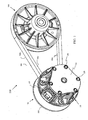
- the CVT system 100 includes a primary clutch 102 and a secondary clutch 104.
- the primary clutch 102 is coupled to receive a rotational output from an engine (not shown).
- the secondary clutch provides a rotational output to a drive train (not shown).
- An endless looped drive belt 106 rotationally couples the primary clutch 102 and the secondary clutch 104.
- the primary clutch 102 includes a first sheave portion 108 and a second sheave portion 110.
- the second sheave portion 110 is axially movable in relation to the first sheave portion 108.
- a sheave moving assembly 112 of the primary clutch 102 is designed to selectively move the second sheave portion 110 in relation to the first sheave portion 108.
- a cover 114 and fasteners 158 that attach the cover 114 to the second sheave portion 110.
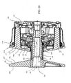
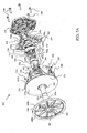
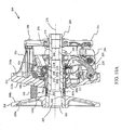
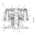
- Figures 2A and 2B illustrate a primary clutch 102 of one embodiment.
- Figure 2A illustrates an unassembled side perspective view of the primary clutch 102
- Figure 2B illustrates an assembled cross-sectional side view of the primary clutch 102.
- the primary clutch 102 includes the first sheave portion 108 and the second sheave portion 110.
- the first sheave portion 108 includes a first side 108a and second side 108b.
- the first side 108a of the first sheave portion 108 includes a central opening 122.
- the second side 108b of the first sheave portion 108 includes a first conical-faced surface 107 designed to engage a first side face 106b of a drive belt 106.
- the first sheave portion 108 further includes a post 120 that centrally extends from the first conical-faced surface 107.
- the post 120 includes a bore 121 centered about a rotational axis 170 of the primary clutch 102 as illustrated in Figure 2B .
- the bore 121 is further aligned with the central opening 122.
- Bore 121 is designed to receive a rotational output from an engine (not shown).
- bore 121 is designed to engage a crankshaft (not shown) of an engine that is passed through the central opening 122.
- other mechanisms provide the rotational output of the engine to the primary clutch 102.
- the first sheave portion 108 and the post 120 rotate in response to the rotational output of the engine.
- a bearing 136 is received around a portion of the post 120.
- bearing 136 is a cylindrical bearing.
- other types of bearings are used including, but not limited to, roller element bearings, plain bearings and the like.
- a cylindrical sleeve coupler 138 is further received around bearing 136 so that bearing 136 is positioned between the sleeve coupler 138 and a surface 120a of the post 120.
- the sleeve coupler 138 in this embodiment has an engaging surface 138c designed to engage an inner face 106a of a drive belt 106.
- the sleeve coupler 138 further includes a first end 138a and a second end 138b.
- the first end 138a is positioned proximate the first conical faced surface 107 of the first sheave portion 108.
- the second end 138b of the sleeve coupler 138 includes a plurality of sleeve coupler dogs 139.
- the second sheave portion 110 of the primary clutch 102 includes a first side 110a and a second side 110b.
- the first side 110a of the second sheave portion 110 includes a second conical-faced surface 111.
- the second conical-faced surface 111 is designed to engage a second side face 106c of a drive belt 106.
- the second sheave portion 110 further includes a central sheave passage 124.
- the central sheave passage 124 is received around the sleeve coupler 138 such that the first conical-faced surface 107 of the first sheave portion 108 faces the second conical-faced surface 111 of the second sheave portion 110.
- a bushing 128 is positioned between a portion of a surface that defines opening 124 of the second sheave portion 110 and the sleeve coupler 138.
- bushing 128 is any type of plain bearing.
- the second sheave portion 110 further has a plurality of arm extending portions 126 (bosses) that extend out generally perpendicular proximate an outer perimeter 115 of the second side 1 10b of the second sheave portion.
- the primary clutch 102 further includes a ramp coupler 140.
- the ramp coupler 140 has a first side 140a and a second side 140b and a central ramp coupler passage 141.
- the central ramp coupler passage 141 is received around a portion of the post 120 of the first sheave portion 108.
- the first side 140a of the ramp coupler has a plurality of ramp coupler dogs 143 configured to mate with the sleeve coupler dogs 139 of the sleeve coupler 138 to provide a rotational coupling between the ramp coupler 140 and the sleeve coupler 138.
- the second end 140b of the ramp coupler 140 includes at least one coupler ramp 145.
- the primary clutch 102 further includes a one way clutch 150 (OWC) that has a central roller clutch passage 151.
- the central roller clutch passage 151 is received around a portion of the post 120 of the first sheave portion 108.
- the OWC 150 includes a first side 150a, a second side 150b and outer perimeter 150c.
- the OWC 150 further includes at least one clutch ramp 155 that extends radially out from a surface that defines the outer perimeter 150c.
- the at least one clutch ramp 155 extends axially.
- the OWC includes at least one follower and at least one clutch ramp 155.
- the at least one clutch ramp 155 is positioned to selectively engage the at least one coupler ramp 145 of the ramp coupler 140. Movement of the at least one clutch ramp 155 of the OWC 150 in relation to the at least one coupler ramp 145 of the ramp coupler 140 provides engine braking functions as further discussed in detail below.
- Cover 114 includes a central cover opening 115.
- the central cover opening 115 receives an end of the post 120 of the first sheave portion 108.
- the cover 114 has a plurality of apertures that align with threaded bores (not shown) in the arm extending portions 126 (bosses) of the second sheave portion 110.
- Fasteners 158 such as bolts, are passed through the plurality of the apertures in the cover 114 and are threadably engaged with the threaded bores in the arm extending portions 126 of the second sheave portion 110.
- the primary clutch 102 also includes a spider 154.
- the spider 154 includes a first side 154a, a second side 154b and a central spider passage 153.
- the central spider passage 153 is received around and coupled to a portion of the post 120 of the first sheave portion 108.
- the spider 154 is solidly coupled about connection 160 as illustrated in Figure 2B .
- the connection 160 is mated threads. This connection 160 keeps the spider 154 static in relation to the post 120 thereby preventing the spider 154 from moving axially along the axis of rotation 170.
- the spider 154 is positioned between the cover 114 and the second sheave portion 110 as illustrated.
- the spider 154 further includes radially extending arms 165. Each radially extending arm 165 holds an engaging pin/roller subassembly 157.
- a washer 152 is positioned between the second side 150b of the OWC 150 and surface 154c of the first side 154a of the spider 154.
- a biasing member 156 is positioned between the second side 154b of the spider 154 and the cover 114.
- the biasing member 156 which in this embodiment is a spring, provides a biasing force separating the spider from the cover 114.
- the biasing force of the biasing member 156 forces the second sheave portion 110 away from the first sheave portion 108 and towards the spider 154.
- a plurality of flyweight members 130 are rotationally coupled the second side 110b of the second sheave portion 110.
- each flyweight 130 has a flyweight passage 131 that is rotationally mounted on a pivot rod 132.
- Each pivot rod 132 is coupled to the second sheave portion 110 via connector 134.
- the plurality of the flyweights 130 are designed to pivot on the pivot rod 132 such that an engaging surface 130a of the flyweights 130 moves towards the first side 154a of the spider 154 in response to select angular rotational speeds of the second sheave portion 110.
- a centrifugal force created by the rotation of the second sheave portion 110 causes the flyweights 130 to pivot about pivot rods 132 causing the engaging surfaces 130a of the flyweights 130 to push on the engaging pin/roller subassemblies 157 of spider 154.
- This push force counters the biasing force created by biasing member 156 thereby moving the second sheave portion 110 closer to the first sheave portion 108 and away from the spider 154.
- embodiments of the present invention implement engine braking.
- the second sheave portion 110 is not rotating fast enough for the push force of the flyweights 130 to counter the biasing force of the biasing member 156.
- the ramp coupler 140 and the OWC 150 work together to counter the biasing force of biasing member 156.
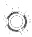
- one of the devices used in embodiments of the engine braking mechanism is the OWC 150.
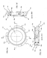
- An illustration of an embodiment of an OWC 150 is provided in Figures 3A through 3D .
- Figure 3A illustrates a top view of OWC 150.
- the OWC 150 has a body that is generally ring shaped having an outer perimeter 150c and a central passage 151.
- the central clutch passage 151 is received around surface portion 120a of post 120 of the first sheave portion 108.
- This embodiment of the OWC 150 includes a plurality of clutch ramps designated as 155a, 155b and 155c (moving members).
- Ramps 155a, 155b and 155c in this embodiment generally extend radially outward from a surface that defines the outer perimeter 150c of the OWC 150.
- the ramps extend forward axially.
- the direction of the clutch ramps 155a, 155b and 155c is not limited to extending radially.
- the ramp coupler 140 has three coupler ramps 145 to respectively engage the three clutch ramps 155a, 155b and 155c.
- the OWC 150 includes pin roller 182a that is positioned between a first plain bearing 180a and a second plain bearing 180b.
- the plain bearings 180a and 180b are pressed into their respective positions. In other embodiments, other types of bearings are used.
- a cover 181 is positioned on the first side 150a of the OWC 150 to keep dust out of the OWC 150.
- a set screw opening 184a provides access to a set screw 186a.
- Set screw opening 184c and set screw 186c is further illustrated in the side view of the OWC 150 of Figure 3D.
- Figure 3D further illustrates the shape of ramps 155a and 155b in this embodiment.
- the clutch ramps 155a, 155b and 155c include a flat section 155e.
- the clutch flat section 155e engages a corresponding flat section on a corresponding coupler ramp 145 of a ramp coupler 140 in an overrunning mode described further below.
- FIG. 3E A cross-sectional view along section line CC of Figure 3D is illustrated in Figure 3E.
- Figure 3E further illustrates set screws 186a, 186b and 186c.
- each set screw 186a, 186b and 186c has an associated opening 184a, 184b and 184c that allow access to the respective set screws 186a, 186b and 186c that are threadably engaged with internal threads of respective biasing member passages 185a, 185b and 185c.
- the set screw passages 185a, 185b and 185c extend from the outer perimeter 150c of the OWC 150 to the associated internal cavities 190a, 190b and 190c.
- the set screws 186a, 186b and 186c are each respectively engaged with pin roller biasing members 188a, 188b and 188c.
- the biasing members 188a, 188b and 188c are received in respective plungers 189a, 189b and 189c.
- the plungers 189a, 189b and 189c contact respective pin rollers 182a, 182b and 182c that are in respective cavities 190a, 190b and 190c.
- the biasing members can be made from any type of material that provides a biasing force such as, but not limited to, compression springs, wire form springs, rubber elements, and the like.
- the shape of the respective cavities 190a, 190b and 190c and contact of the respective plungers 189a, 189b and 189c on the respective pin rollers 182a, 182b and 182c only allow the OWC 150 to rotate in one direction in relation to post 120 of the first sheave portion 108.
- a biasing force from the biasing members 188a, 188b and 188c force the associated pin rollers 182a, 182b and 182c along associated ramped surfaces 197a, 197b and 197c in the respective cavities 190a, 190b and 190c such that a portion of the pin rollers 182a, 182b and 182c engage a shaft, such as post 120, received in passage 151 of the OWC 150 to prevent the OWC 150 from rotating in respect to the post 120 in a first direction.
- the pin rollers 182a, 182b and 182c are received within the respective cavity 190a, 190b and 190c to allow the OWC 150 to rotate in relation to the post 120 in a second direction.
- Adjustment of force on the pin rollers 182a, 182b and 182c is accomplished by adjusting the respective set screws 186a, 186b and 186c in this embodiment.
- the pin rollers 182a, 182b and 182c are set to lock the OWC 150 to rotate with the post 120 of the first sheave portion 108 in a first direction and allow the OWC 150 to move independent (overrunning mode) of the rotation of the post 120 in the other direction as described above.
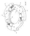
- a further illustration of the OWC is provided in the cross-sectional side perspective view of Figure 3F .
- pin rollers are set at the manufacture and set screws are not used. An example of a pre-set embodiment is illustrated in Figure 9B below.
- OWC 150 is one example of an OWC that can be used. Any type of OWC or roller OWC known in the art that allows relative rotation in a first direction and disallows relative rotation in a second direction can be used.
- Figures 4A through 6B Further illustrations describing the operation of the primary clutch 102 are provided in Figures 4A through 6B .
- Figure 4A and 4B illustrate cross-sectional views of the primary clutch 102 and drive belt 106.
- Figure 4B is a close up view of relevant portions of the primary clutch 102 and drive belt 106.
- Figures 4A and 4B illustrate the primary clutch 102 during an idle operation mode. During idle situations, only the inner face 106a of the drive belt engages the engaging surface 138c of the sleeve coupler 138.
- the second conical-faced surface 111 of the second sheave portion 110 is spaced a distance away from the first conical-faced surface 107 of the first sheave portion 108 so there is a gap 151 between a second side face 106c of the drive belt 106 and the second conical-faced surface 111 of the second sheave portion 110.
- a gap may also be (or may be in place of gap 151) between the first side face 106b of the drive belt 106 and the first conical-faced surface 107 (not shown).
- the gap 151 between the first conical-faced surface 107 of the first sheave portion 108 and the second conical-face surface 111 of the second sheave portion 110 is maintained by biasing member 156 during the idle operational mode.
- the at least one ramp 145 extending from the second side 140b of the ramp coupler 140 and the at least one ramp (generally designated as 155) on the OWC 150 are not engaged to ramp up the ramp coupler 140 from the OWC 150 since the OWC 150 is overrunning about surface portion 120a of the post 120.
- flats 145e on the at least one ramp 145 of the ramp coupler are coupling flats 155e on the at least one ramp 155 of the OWC during idle mode operation.
- the engaging surface 130a of the flyweight 130 is in a neutral position that is away from the first side 154a of the spider 154.
- FIG. 5A and 5B Cross-sectional views of the primary clutch 102 in an activation operational mode are illustrated in Figures 5A and 5B.
- Figure 5B is a close up view of relevant portions of primary clutch 102.
- the flyweights 130 are pivoted towards the first surface 154a of the spider 154 due to the centrifugal forces caused by the rotation of the primary clutch 102.
- a push force is generated by the engaging surface 130a of the flyweights 130 on the engaging pin/roller subassemblies 157 of the spider 154.
- This push force counters the biasing force of the biasing member 156 on the spider 154 thereby moving the second sheave portion 110 closer to the first sheave portion 108 of the primary clutch 102.
- the faster the rotation of the primary clutch 102 the stronger the centrifugal force (and hence the push force) and the closer the second sheave portion 110 is moved towards the first sheave portion 108.
- Figures 5A and 5B illustrate, as the second sheave portion 110 moves towards the first sheave portion 108 the first conical-faced surface 107 of the first sheave portion 108 and the second conical-faced surface 111 of the second sheave portion 110 engage respective side faces 106b and 106c of the drive belt.
- the primary clutch 102 is designed to only allow the second sheave portion 110 to move a select distance towards the first sheave portion 108 so the drive belt 106 remains contained between the first and second conical-faced surfaces 107 and 111.
- the friction between the engaged side faces 106b and 106c of the drive belt 106 with the respective conical-faced surfaces 107 and 111 cause the drive belt 106 to move with the rotation of the primary clutch 102.
- the drive belt 106 in turn provides rotation to the secondary clutch 104 to power the drive train in the non-engine braking operational mode.
- Figures 6A and 6B illustrate a cross-sectional side view of the primary clutch 102 in an engine braking operational mode.
- Figure 6B is a close up view of relevant portions of the primary clutch 102.
- EBS engine braking system
- the primary clutch 102 will not be rotationally connected to the secondary clutch 104 that is coupled to a drive train of the vehicle.
- An example situation where this can occur is when the operator of the vehicle lets off on the gas while the vehicle is traveling down a steep incline.
- the drive belt in this situation, will be essentially disconnected (in an idle configuration as discussed above) from the primary drive because slip will occur when the conical faced surfaces 107 and 111 no longer engage the sides 106b and 106c of the belt 106 and the inner surface 106a of the belt 106 moves away from the post 120 to allow free rotational movement of the post 120 and engine during idle.
- the vehicle in a typical CVT system without EBS, the vehicle must rely on other braking means during this situation. Other braking means, however, may not be adequate in all situations.
- the flyweights 130 are not subject to significant centrifugal forces that cause the engaging surface 130a of the flyweight 130 to pivot towards the first side 154a of the spider 154. This is because the rotation speed of the primary clutch 102 is relatively low (and hence so is the rotational output of the engine as the result of letting up on the throttle) in an engine braking situation. Therefore, the flyweights 130 cannot be used to force the second sheave portion 110 towards the first sheave portion 108 in this situation. In the engine braking situation, the secondary clutch 104 is pushing the belt 106 to a maximum radius on the secondary clutch 104 and thus to a minimum radius on the primary clutch 102.
- the drive belt 106 that is rotationally coupled to the secondary clutch 104 will move the sleeve coupler 138 (which the inner face 106a of the belt drive is engaged with) faster than the post 120 of the first sheave portion 108. Therefore, the sleeve coupler 138 will rotate in relation to the post 120 of the first sheave portion 108 to try and overrun the post 120.
- the ramp coupler 140 Since, the sleeve coupler dogs 139 are engaged with the ramp coupler dogs 143 of the ramp coupler 140, the ramp coupler 140 also rotates in relation to post 120. This rotation of the ramp coupler 140 causes the at least one coupler ramp 145 to slideably engage the at least one ramp 155 of the OWC 150.
- the OWC 150 is designed to remain synchronous with the belt and the ramp coupler while allowing the post to rotate (engine idling) but lock up with the post 120 in the other direction of rotation while engine braking where the at least one coupler ramp 145 of the ramp coupler 140 will rotate in relation to the at least one clutch ramp 155 of the OWC 150.
- the rotation of the at least one ramp 145 in relation to the at least one ramp 155 causes second side 140b of the ramp coupler 140 to axially move away from the first side 150a of the OWC 150 to form a gap 195. Since the second side 150b of the OWC 150 is positioned against the thrust washer 152 and the thrust washer 152 abuts surface 154c of the non-axially moving spider 154, the ramp coupler 140 is forced to move axially towards the second sheave portion 110.
- the first side 140a of the ramp coupler 140 pushes on bushing 128 (which is a flanged plain bearing in this embodiment) countering the biasing force of the biasing member 156 to move the second sheave portion 110 towards the first sheave portion 108 a select distance.
- Free play in the rotational coupling between the sleeve coupler dogs 139 of the sleeve coupler 138 and the ramp coupler dogs 143 of the ramp coupler 140 allows movement of the ramp coupler 140 axially towards the second sheave portion 110.
- the movement of the second sheave portion 110 towards the first sheave portion 108 causes the drive belt 106 to be frictionally engaged on three sides.
- the inner face 106a of the drive belt 106 is engaged with the engaging surface 138c of the sleeve coupler 138
- the first side face 106b of the drive belt 106 is engaged with the first conical-faced surface 107 of the first sheave portion 108
- the second side face 106c of the drive belt 106 is engaged with the second conical-faced surface 111 of the second sheave portion 110.
- This action reconnects the engine to the drive train via the drive belt 106 and the primary and secondary clutches 102 and 104 to allow for engine braking.
- the engagement of each of the three of the drive belt face surfaces 106a, 106b and 106c are needed to create enough friction to overcome the rotation forces provided by the drive train in applications were the vehicle is relatively heavy.
- This rotation causes the second side 140b the ramp coupler 140 to be positioned once again proximate the first side 150a to the OWC 150 where the flat 145e of the at least one coupler ramp 145 of the ramp coupler 140 couples the flat 155e of the at least one ramp 155 of the OWC 150 thereby removing the force on the second sheave portion 110 by the ramp coupler 140.
- the biasing force provided by biasing member 156 further provides the biasing force to push the second side 140b the ramp coupler 140 to be against the first side 150a of the OWC 150 when returning to the idle operational mode.
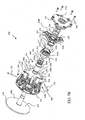
- FIG. 7A illustrates a first unassembled front-side perspective view of the primary clutch 200
- Figure 7B illustrates a second unassembled rear-side view of the primary clutch 200
- the primary clutch 200 includes a first sheave portion 208 and a second sheave portion 210.
- the first sheave portion 208 includes a first side 208a and second side 208b.
- the first side 208a of the first sheave portion 208 includes a central opening 222.
- the second side 208b of the first sheave portion 208 includes a first conical-faced surface 207 designed to engage a first side face 106b of a drive belt 106.
- the first sheave portion 208 further includes a post 220 that centrally extends from the first conical-faced surface 207.
- the post 220 includes a bore 221 centered about a rotational axis 270 of the primary clutch 200 as illustrated at least in Figure 10A .
- the bore 221 is further aligned with the central opening 222.
- Bore 221 is designed to receive a rotational output from an engine (not shown).
- bore 221 is designed to engage a crankshaft (not shown) of an engine that is passed through the central opening 222.
- other mechanisms provide the rotational output of the engine to the primary clutch 200.
- the first sheave portion 208 and the post 220 rotate in response to the rotational output of the engine.
- the second sheave portion 210 of the primary clutch 200 includes a first side 210a and a second side 210b as illustrated in Figures 7A and 7B .
- the first side 210a of the second sheave portion 210 includes a second conical-faced surface 211.
- the second conical-faced surface 211 is designed to engage a second side face 106c of a drive belt 106.
- the second sheave portion 210 further includes a central sheave passage 224.
- a sleeve coupler 306 is received around a first portion 220a of the post 220 of the first sheave portion 208.
- the sleeve coupler 306 includes a first internal set of needle bearings 307a and a second set of needle bearings 307b that engage a surface of the first portion 220a of the post 220.
- An illustration of the sleeve coupler 306 received on the first portion 220a of the post 220 is illustrated in Figures 10A through 10C .
- Sleeve coupler 306 included a flange 306b that protrudes from an outer surface 306a of the sleeve coupler 306.
- a first thrust washer 302 and a first seal 304 are position between an end of the sleeve coupler 306 and the second side 208b of the first sheave 208 as illustrated in Figure 10A through 10C .
- a bushing 311 in the central opening 224 of the second sheave portion 210 contacts a portion of the outer surface 306a of the sleeve coupler 306. Moreover, an edge of the bushing 311 abuts one side of the flange 306b of the sleeve coupler 306.
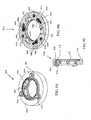
- the second sheave portion 210 further has a plurality of arm extending portions 226 (bosses) that extend out generally perpendicular proximate an outer perimeter 217 of the second side 210b of the second sheave portion 210. This is illustrated in the rear perspective view of the second sheave portion 210 of Figure 8 . Further illustrated in Figure 8 , is a braking ramp rim 500 that extends around an opening to the central passage 224 of the second sheave portion 210. The braking ramp rim 500 has a height from the second side 210b of the second sheave portion 210 that varies. In particular, in this embodiment, the braking ramp rim 500 varies from three low height positions 500b to three high height positions 500a.
- the different between a low height position 500b and a high height position 500a is in a range of .020 of an inch to .500 of an inch.
- the difference can be more or less depending on the application (i.e. the size of the vehicle, the brake torque needed, etc).
- Torque buttons 412a, 412b and 412c (moving members) in a one way clutch 314 described below engage the braking ramp rim 500 to selectively move the second sheave portion 210 towards the first sheave portion 208 during an engaging braking situation in this embodiment as described below.
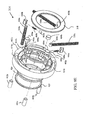
- the OWC 314 includes a housing 402 with a first side 402a, a second side 402b and a central passage 402c. Similar to the embodiment described above, the housing 402 includes internal cavities 408a, 408b and 408c as illustrated in Figure 9B . Pin rollers 404a, 404b and 404c are received in the respective internal cavities 408a, 408b and 408c. Pin roller biasing members 406a, 406b and 406c are also received in the internal cavities 408a, 408b and 408c.
- the biasing members 406a, 406b and 406c exert a biasing force on the respective pin rollers 404a, 404b and 404c towards one end of the respective cavities 408a, 408b and 408c.
- Each of the cavities 408a, 408b and 408c has an opening into the central passage 402c of the housing 402.
- the central passage 402c is received around the outer surface 306a of the sleeve coupler 306 as illustrated in Figures 10A through 10C .
- the shape of the internal cavities 408a, 408b and 408c and the biasing members 406a, 406b and 406c allow the OWC 314 to rotate independent of the rotation of the sleeve coupler 306 in one direction and lockup the OWC 314 with the sleeve coupler 306 in the other direction (i.e. where the respective pin rollers 404a, 404b and 404c engage the outer surface 306a of the sleeve coupler 306).
- each pin roller biasing member 406a, 406b and 406c includes a spring block retainer 440a, 440b and 440c and a plunger 442a, 442b, 442c as seen in Figures 9D and 9E .
- the spring block retainers 440a, 440b and 440c are designed to receive a first end of respective biasing members 406a, 406b and 406c (which are springs in this embodiment).
- the plungers 442a, 442b and 442c are designed to receive a second end of the respective biasing members 406a, 406b and 406c.
- the spring block retainers 440a, 440b and 440c help retain the first end of the biasing members 406a, 406b and 406c within the respective cavities 408a, 408b and 408c.
- the plungers 442a, 442b and 442c on the second end of the biasing members 406a, 406b and 406c engage the respective pin rollers 404a, 404b and 404c.
- the first side 402a of the housing 402 of the OWC 314 in this embodiment includes bores 411a, 411b and 411c.
- the bores 411a, 411b and 411c are illustrated in Figures 9B and 9D .
- Torque buttons 412a, 412b and 412c are received in the respective bores 411a, 411b and 411 c.
- the torque buttons 412a, 412b and 412c each have an end that extends out beyond the first side 402a of the housing 402 of the OWC 314 as illustrated in Figure 9C .
- the end of the torque buttons 412a, 412b and 412c are aligned with the braking ramp rim 500 of the second sheave portion 210.
- torque buttons 412a, 412b and 412c are positioned proximate the low height positions 500b of the braking ramp rim 500.
- the rotation of the OWC 314 and the sleeve coupler 306 causes the torque buttons 412a, 412b and 412c to rotate from the low height positions 500b towards the high height positions 500a along the ramp profile of the braking ramp rim 500. This action forces the second sheave 210 toward the first sheave 208 in an engine braking situation as further discussed below.
- a seal 422 and a bearing 424 are positioned proximate the first side 402a and central passage 402c of the housing 402 of the OWC 314.
- the torque buttons 412a, 412b and 412c are coupled to the OWC 314 and the braking ramp rim 500 is on the second sheave portion 210, an opposite arrangement could be used having the same desired effect.
- any engine braking assembly that effectively moves the second sheave portion 210 towards the first sheave portion 208 as the result of the sleeve coupler 306 attempting to overrun the post 220 is contemplated.
- the OWC 314 is described as roller pin OWC, any type of OWC can be used such as, but not limited to, roller clutches, sprag clutches, etc.
- the second side 402b of the housing 402 of the OWC 314 includes three slots 414a, 414b and 414c.
- Three return biasing members 320a, 320b, 320c are received in the respective three slots 414a, 414b and 414c as illustrated in Figure 9F .
- One end of each return biasing members 320a, 320b, 320c is coupled to a respective biasing pin connector 430a, 430b and 430c.
- Spider pins 254a and 254b (and a third pin not shown in Figure 7A ) on spider 254 passing though apertures 317 in thrust washer 316 (shown in Figure 7A ) are designed to be received in respective connectors 430a, 430b and 430c of the return biasing members 320a, 320b and 320c.
- This arrangement of the return biasing members 320a, 320b, and 320c allows the OWC 134 to return to a non-torque position (i.e. the torque buttons being position proximate the low height position 500b of the braking ramp rim 500) after an engine braking situation has passed.
- bearing 426 positioned proximate the second side 402b of the housing 402 of the OWC 314 and seal 318 that is positioned about the second side 402b of the housing 402 of the OWC.
- the primary clutch 200 includes a cover 214 with a central opening 214a.
- the central cover opening 214a receives an end of the post 220 of the first sheave portion 208.
- the cover 214 has a plurality of apertures that align with threaded bores (not shown) in the arm extending portions 226 (bosses) of the second sheave portion 110.
- Fasteners 258, such as bolts, are passed through the plurality of the apertures in the cover 214 and are threadably engaged with the threaded bores in the arm extending portions 226 of the second sheave portion 210.
- the primary clutch 200 also includes the spider 254.
- the spider 254 includes a first side 254a, a second side 254b and a central spider passage 254c.
- the central spider passage 254c is received around and coupled to a portion of the post 220 of the first sheave portion 208.
- the spider 254 is solidly coupled about connection 260 as illustrated in Figure 10A .
- the connection 260 is mated threads. This connection 260 keeps the spider 254 static in relation to the post 220 thereby preventing the spider 254 from moving axially along the axis of rotation 270.
- the spider 254 is positioned between the cover 214 and the second sheave portion 210 as illustrated.
- the spider 254 further includes radially extending arms 265.
- Each radially extending arm 265 holds an engaging pin/roller subassembly 257.
- a washer 318 is positioned between an end of the sleeve coupler 306 and the first side 254a of the spider 254.
- a biasing member 256 is positioned between the second side 254b of the spider 254 and the cover 214.
- the biasing member 256 which in this embodiment is a spring, provides a biasing force separating the spider 254 from the cover 214.
- the biasing force of the biasing member 256 forces the second sheave portion 210 away from the first sheave portion 208 and towards the spider 254.
- a plurality of flyweight members 230 are rotationally coupled the second side 210b of the second sheave portion 210.
- each flywheel 230 has a flyweight passage 231 that is rotationally mounted on a pivot rod 232.
- Each pivot rod 232 is coupled to the second sheave portion 210 via connector 234.
- the plurality of the flyweights 230 are designed to pivot on the pivot rod 232 such that an engaging surface 230a of the flyweights 230 moves towards the first side 254a of the spider 254 in response to select angular rotational speeds of the second sheave portion 210.
- a centrifugal force created by the rotation of the second sheave portion 210 causes the flyweights 230 to pivot about pivot rods 232 causing the engaging surfaces 230a of the flyweights 230 to push on the engaging pin/roller subassemblies 257 of spider 254.
- This push force counters the biasing force created by biasing member 256 thereby moving the second sheave portion 210 closer to the first sheave portion 208 and away from the spider 254.
- FIG. 10A a cross-sectional view of the primary clutch 200 in an activation operational mode is illustrated.
- the flyweights 230 are pivoted towards the first surface 254a of the spider 254 due to the centrifugal forces caused by the rotation of the primary clutch 200.
- a push force is generated by the engaging surface 230a of the flyweights 230 on the engaging pin/roller subassemblies 257 of the spider 254.
- This push force counters the biasing force of the biasing member 256 on the spider 254 thereby moving the second sheave portion 210 closer to the first sheave portion 208 of the primary clutch 202.
- the first conical-faced surface 207 of the first sheave portion 208 and the second conical-faced surface 211 of the second sheave portion 210 engage respective side faces 106b and 106c of the drive belt 106.
- the drive belt 106 is forced farther away from the rotational axis 270.
- the primary clutch 200 is designed to only allow the second sheave portion 210 to move a select distance towards the first sheave portion 208 so the drive belt 106 remains contained between the first and second conical-faced surfaces 207 and 211.
- the primary clutch 200 is illustrated during an idle operation mode.
- the second conical-faced surface 211 of the second sheave portion 210 is spaced a distance away from the first conical-faced surface 207 of the first sheave portion 208 so there is a gap 501 between a second side face 106c of the drive belt 106 and the second conical-faced surface 211 of the second sheave portion 210.
- a gap may also be (or may be in place of gap 501) between the first side face 106b of the drive belt 106 and the first conical-faced surface 207 (not shown).
- the gap 501 between the first conical-faced surface 207 of the first sheave portion 208 and the second conical-face surface 211 of the second sheave portion 210 is maintained by biasing member 256 during the idle operational mode.
- friction between the inner face 106a of the drive belt 106 and the outer surface 306a of the sleeve coupler 306 prevents sleeve coupler 306 from turning while post 220 rotates with the rest of the primary clutch 200 that is engaged to receive the rotational output of the engine.
- the engine in the idle operational mode, the engine is disconnected from the drive train because the drive belt 106 is coupled only to the sleeve coupler 306 and the OWC 314 (which is overrunning) provides no moving force to the secondary clutch 104.
- the torque buttons 412a, 412b and 412c of the OWC 314 are in a non-torque position (i.e. the torque buttons being position proximate the low height position 500b of the braking ramp rim 500 of the second sheave portion 210.
- Figure 10C illustrates the primary clutch 200 in the engine braking operational mode.
- the flyweights 230 are not subject to significant centrifugal forces that cause the engaging surface 230a of the flyweight 230 to pivot towards the first side 254a of the spider 254. This is because the rotation speed of the primary clutch 200 is relatively low (and hence so is the rotational output of the engine as the result of letting up on the throttle) in an engine braking situation. Therefore, the flyweights 230 cannot be used to force the second sheave portion 210 towards the first sheave portion 208 in this situation.
- the secondary clutch 104 is pushing the belt 106 to a maximum radius on the secondary clutch 104 and thus to a minimum radius on the primary clutch 200.
- the drive belt 106 that is rotationally coupled to the secondary clutch 104 will move the sleeve coupler 306 (which the inner face 106a of the belt drive is engaged with) faster than the post 220 of the first sheave portion 208. Therefore, the sleeve coupler 306 will rotate in relation to the post 220 of the first sheave portion 208 to try an overrun the post 220.
- the OWC 314 is designed to rotate independently of the sleeve coupler 306 while the sleeve coupler rotates in one direction in relation to the OWC 314 (engine idling) but lock up with the sleeve coupler 306 when the sleeve coupler 306 rotates in the other direction of rotation in relation to the OWC (engine braking).
- the rotation of the OWC 314 and the sleeve coupler 306 causes the torque buttons 412a, 412b and 412c to rotate to engage the ramp rim 500 moving towards the high height positions 500a from the low positions 500b.
- This action forces the second sheave 210 toward the first sheave 208 thereby countering the bias force supplied by bias member 256.
- This action reconnects the engine to the drive train via the drive belt 106 and the first and second clutches 200 and 104 to allow for engine braking.
- the engagement of each of the three of the drive belt face surfaces 106a, 106b and 106c are needed to create enough friction to overcome the rotation forces provided by the drive train in applications were the vehicle is relatively heavy.
- the engagement of the drive belt 106 as described above in the engine braking operation mode will continue as long as the secondary clutch 104 is providing a force on the drive belt 106 as the result of the drive train trying to move the second clutch 104 faster than the first clutch 200 (primary clutch).
- rotation of the post 220 of the first sheave portion 208 of the first clutch 200 will be faster than the rotation of the secondary clutch 104.
- the return biasing members 320a, 320b, and 320c allows the OWC 314 to return to a non-torque position (i.e. the torque buttons being position proximate the low height position 500b of the braking ramp rim 500) after an engine braking situation has passed.
- Embodiments of the CTV 100 system can be used with any type of vehicle including, but not limited to, all-terrain vehicles (ATVs), utility vehicles, golf carts, cars, trucks, boats etc.
- the drive belt 106 used with the CVT system may be made from any type of material that provides adequate rotational communication between the primary sheave 102, 200 and the secondary sheave 104 for a given application.
- Examples of drive belt materials include, but are not limited to, rubber, polyurethane, urethane, neoprene, fiber reinforced materials as well as drive belts made from metals.
Landscapes
- Engineering & Computer Science (AREA)
- General Engineering & Computer Science (AREA)
- Mechanical Engineering (AREA)
- Transmissions By Endless Flexible Members (AREA)
- Pulleys (AREA)
- Transmission Devices (AREA)
Description
- Continuously variable transmission (CVT) systems are used in vehicles to change transmission ratios between an engine output and a drive train of the vehicle. In a typical CVT system, a primary clutch is coupled to receive a rotational output from an engine and a secondary clutch is coupled to provide a rotational output to the drive train. The primary clutch is coupled to provide rotation to the secondary clutch with an endless loop drive belt. In changing transmission ratios, typically the primary clutch is comprised of first and second conical-faced sheave portions that are configured in a way to move the second conical-faced sheave portion axially in relation to the first conical-faced sheave portion along an axis of rotation. In this system the distance between the sheaves of the primary clutch determines the positioning of the drive belt in relation to the rotational axis and hence the transmission ratio. In particular, the closer the first and second sheave portions are positioned together, the farther the drive belt is pinched on the conical-faces away from the rotational axis of the primary clutch. Likewise, the farther the first and second sheave portions are positioned away from each other, the closer the drive belt is the rotational axis of the primary clutch. When the engine is at idle speeds, the first and second sheaves of the primary clutch are axially positioned at a select distance from each other so at least one of the conical faced sheave portions does not engage a side of the drive belt. In this situation, the limited friction between the drive belt and the primary clutch allows the belt to slip so no rotational force is applied to the secondary sheave and hence no power is provided to the drive train by the engine.
- Typically CVT systems as described above do not allow for engine braking. Engine braking is a term used to describe when the engine of a vehicle is used to provide at least some of the braking for the vehicle. An example situation where engine braking is beneficial occurs when a vehicle is going down a steep incline and the operator cuts back on the throttle. In this situation the engine's rotational output will be slower than the rotation of the drive train. In an engine braking scheme, the slow rotation of the engine is used to slow down the rotation of the drive train. However, since the drive belt on a typical CVT system is designed to slip on the primary clutch during idle speeds of the motor, the engine effectively is disconnected from the drive train. This disconnection between the engine and the drive train prevents a typical CVT system from implementing engine braking. In this situation, other traditional braking means must be employed which may or may not be effective in a given situation.
- For the reasons stated above and for other reasons stated below which will become apparent to those skilled in the art upon reading and understanding the present specification, there is a need in the art for an efficient and effective engine braking mechanism in a CVT system.
-
US-A-2002/0033295 discloses an all-terrain vehicle having a frame with front, rear, right, and left sides. The all-terrain vehicle includes an engine with at least one cylinder having an axis that defines an engine centreline. The all-terrain vehicle also includes an output shaft defining an output shaft centreline. A continuously variable transmission ("CVT") operatively connects the engine to the output shaft and defines a CVT centreline. To provide the ability to brake the all-terrain vehicle when the engine is operating, and to provide a reverse torque transmission ("RTT"), a mechanism to permit free wheel operation is included. In particular, the CVT incorporates a slide sleeve on the drive pulley. The slide sleeve cooperates with one or more spring loaded pins to affect its operation. The slide sleeve has two modes of operation. The first is the non-engaged mode where the slide sleeve permits the inner and outer halves of the drive gear to rotate without imparting any torque to the belt. The second operational mode permits the CVT to act as a RTT to impart torque from the wheels of the all-terrain vehicle to the engine. - The above-mentioned problems of current systems are addressed by embodiments of the present invention and will be understood by reading and studying the following specification. The following summary is made by way of example and not by way of limitation. It is merely provided to aid the reader in understanding some of the aspects of the invention.
- The present invention provides a primary clutch assembly comprising: a first sheave portion having a first conical-faced surface, the first conical-faced surface configured to engage a first side face of a drive belt, the first sheave portion further having a post centrally extending from the first conical-faced surface; a cylindrical sleeve coupler rotationally mounted on a portion of the post proximate the first conical-faced surface, the sleeve coupler having an engaging surface configured to engage an inner face of the drive belt; a second sheave portion having a central passage rotationally mounted on the sleeve coupler, the second sheave portion having a second conical-faced surface positioned to face the first conical-faced surface of the first sheave portion, the second conical-faced surface configured to engage a second side face of the drive belt; and an engine braking assembly operatively coupled to the second sheave portion and the sleeve coupler to axially move the second sheave portion toward the first sheave portion to engage the first conical-faced surface of the first sheave portion with the first side face of the drive belt and the second conical-faced surface of the second sheave portion with the second side face of the drive belt when the sleeve coupler attempts to overrun the post of the first sheave portion in a rotational direction provided by a rotational output of an engine operatively coupled to the primary clutch.
- The present invention can be more easily understood and further advantages and uses thereof more readily apparent, when considered in view of the detailed description and the following figures in which:
-
Figure 1 is a side perspective view of a CVT system of one embodiment of the present invention; -
Figure 2A is an unassembled side perspective view of a primary clutch of one embodiment of the present invention; -
Figure 2B is an assembled cross-sectional side view of the primary clutch ofFigure 2A ; -
Figure 3A is a top view of one way clutch (OWC) of one embodiment of the present invention; -
Figure 3B is a cross-sectional view along section line AA of the OWC ofFigure 3A ; -
Figure 3C is a cross-sectional view along section line BB of the OWC ofFigure 3A ; -
Figure 3D is a side-view of the OWC ofFigure 3A ; -
Figure 3E is a cross-sectional view of the OWC along section line CC ofFigure 3D ; -
Figure 3F is a cross-sectional side perspective view of the OWC ofFigure 3A ; -
Figure 4A is a side cross-sectional view of a primary clutch with a drive belt in an idle position of one embodiment of the present invention; -
Figure 4B is a close up side cross-sectional view of a portion of the primary clutch ofFigure 4A ; -
Figure 5A is a side cross-sectional view of a primary clutch with a drive belt in an activated position of one embodiment of the present invention; -
Figure 5B is a close up side cross-sectional view of a portion of the primary clutch ofFigure 5A ; -
Figure 6A is a side cross-sectional view of a primary clutch with a drive belt in an engine braking position of one embodiment of the present invention; -
Figure 6B is a close up side cross-sectional view of a portion of the primary clutch ofFigure 6A ; -
Figure 7A is an unassembled front-side perspective view of another embodiment of a primary clutch of the present invention; -
Figure 7B is an unassembled rear-side perspective view of the primary clutch ofFigure 7A ; -
Figure 8 is a rear perspective view of a second sheave portion of one embodiment of the present invention; -
Figure 9A is a top perspective view of a OWC of another embodiment of the present invention; -
Figure 9B is a cross-sectional top view of the OWC ofFigure 9A ; -
Figure 9C is a cross-sectional side view of the OWC ofFigure 9A ; -
Figure 9D is an unassembled front-side view of the OWC ofFigure 9A ; -
Figure 9E is an unassembled back-side view of the OWC ofFigure 9A ; -
Figure 9F is a rear view of the OWC ofFigure 9A ; -
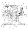
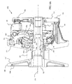
Figure 10A is an assembled cross-sectional side view of the primary clutch ofFigure 7A in an activated position; -
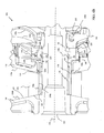
Figure 10B is an assembled cross-sectional side view of the primary clutch ofFigure 7A in an idle position; and -
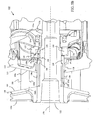
Figure 10C is an assembled cross-sectional side view of the primary clutch ofFigure 7A in an engine braking position. - In accordance with common practice, the various described features are not drawn to scale but are drawn to emphasize specific features relevant to the present invention. Reference characters denote like elements throughout Figures and text.
- In the following detailed description, reference is made to the accompanying drawings, which form a part hereof, and in which are shown by way of illustration specific embodiments in which the inventions may be practiced. These embodiments are described in sufficient detail to enable those skilled in the art to practice the invention, and it is to be understood that other embodiments may be utilized and that changes may be made without departing from the spirit and scope of the present invention. The following detailed description is, therefore, not to be taken in a limiting sense, and the scope of the present invention is defined only by the claims and equivalents thereof.
- Embodiments of the present invention provide an effective engine braking mechanism that engages three surfaces of a drive belt during situations where a secondary clutch has a faster rotational speed than a primary clutch. In embodiments, an engine braking assembly moves a second sheave portion towards a first sheave portion of a primary clutch to engage the drive belt as described above in response to a sleeve coupler of the engine braking assembly (which is driven by the drive belt) attempting to overrun, in a rotational direction, a post of the first sheave portion that is driven by a rotational output of an engine operatively coupled to the primary clutch.
- Referring to
Figure 1 , a side perspective view of aCVT system 100 of an embodiment is illustrated. As illustrated, theCVT system 100 includes aprimary clutch 102 and asecondary clutch 104. Theprimary clutch 102 is coupled to receive a rotational output from an engine (not shown). The secondary clutch provides a rotational output to a drive train (not shown). An endless loopeddrive belt 106 rotationally couples theprimary clutch 102 and thesecondary clutch 104. Theprimary clutch 102 includes afirst sheave portion 108 and asecond sheave portion 110. In this embodiment, thesecond sheave portion 110 is axially movable in relation to thefirst sheave portion 108. In particular, a sheave moving assembly 112 of theprimary clutch 102 is designed to selectively move thesecond sheave portion 110 in relation to thefirst sheave portion 108. Further illustrated inFigure 1 , is acover 114 andfasteners 158 that attach thecover 114 to thesecond sheave portion 110. -
Figures 2A and2B illustrate aprimary clutch 102 of one embodiment. In particular,Figure 2A illustrates an unassembled side perspective view of theprimary clutch 102 andFigure 2B illustrates an assembled cross-sectional side view of theprimary clutch 102. AsFigures 2A and2B illustrate, theprimary clutch 102 includes thefirst sheave portion 108 and thesecond sheave portion 110. Thefirst sheave portion 108 includes afirst side 108a andsecond side 108b. Thefirst side 108a of thefirst sheave portion 108 includes acentral opening 122. Thesecond side 108b of thefirst sheave portion 108 includes a first conical-facedsurface 107 designed to engage afirst side face 106b of adrive belt 106. Thefirst sheave portion 108 further includes apost 120 that centrally extends from the first conical-facedsurface 107. Thepost 120 includes abore 121 centered about arotational axis 170 of theprimary clutch 102 as illustrated inFigure 2B . Thebore 121 is further aligned with thecentral opening 122.Bore 121 is designed to receive a rotational output from an engine (not shown). For example, in one embodiment bore 121 is designed to engage a crankshaft (not shown) of an engine that is passed through thecentral opening 122. In other embodiments, other mechanisms provide the rotational output of the engine to theprimary clutch 102. Thefirst sheave portion 108 and thepost 120 rotate in response to the rotational output of the engine. - A
bearing 136 is received around a portion of thepost 120. In one embodiment, bearing 136 is a cylindrical bearing. In other embodiments other types of bearings are used including, but not limited to, roller element bearings, plain bearings and the like. Acylindrical sleeve coupler 138 is further received around bearing 136 so that bearing 136 is positioned between thesleeve coupler 138 and asurface 120a of thepost 120. Thesleeve coupler 138 in this embodiment has anengaging surface 138c designed to engage aninner face 106a of adrive belt 106. Thesleeve coupler 138 further includes afirst end 138a and asecond end 138b. Thefirst end 138a is positioned proximate the first conicalfaced surface 107 of thefirst sheave portion 108. Thesecond end 138b of thesleeve coupler 138 includes a plurality of sleeve coupler dogs 139. - The
second sheave portion 110 of theprimary clutch 102 includes afirst side 110a and asecond side 110b. Thefirst side 110a of thesecond sheave portion 110 includes a second conical-facedsurface 111. The second conical-facedsurface 111 is designed to engage asecond side face 106c of adrive belt 106. Thesecond sheave portion 110 further includes acentral sheave passage 124. Thecentral sheave passage 124 is received around thesleeve coupler 138 such that the first conical-facedsurface 107 of thefirst sheave portion 108 faces the second conical-facedsurface 111 of thesecond sheave portion 110. Abushing 128 is positioned between a portion of a surface that defines opening 124 of thesecond sheave portion 110 and thesleeve coupler 138. In one embodiment,bushing 128 is any type of plain bearing. Thesecond sheave portion 110 further has a plurality of arm extending portions 126 (bosses) that extend out generally perpendicular proximate anouter perimeter 115 of thesecond side 1 10b of the second sheave portion. - The
primary clutch 102 further includes aramp coupler 140. Theramp coupler 140 has afirst side 140a and asecond side 140b and a centralramp coupler passage 141. The centralramp coupler passage 141 is received around a portion of thepost 120 of thefirst sheave portion 108. Thefirst side 140a of the ramp coupler has a plurality oframp coupler dogs 143 configured to mate with thesleeve coupler dogs 139 of thesleeve coupler 138 to provide a rotational coupling between theramp coupler 140 and thesleeve coupler 138. Thesecond end 140b of theramp coupler 140 includes at least onecoupler ramp 145. Theprimary clutch 102 further includes a one way clutch 150 (OWC) that has a central rollerclutch passage 151. The central rollerclutch passage 151 is received around a portion of thepost 120 of thefirst sheave portion 108. TheOWC 150 includes afirst side 150a, asecond side 150b andouter perimeter 150c. TheOWC 150 further includes at least oneclutch ramp 155 that extends radially out from a surface that defines theouter perimeter 150c. In another embodiment (not shown), the at least oneclutch ramp 155 extends axially. In still another embodiment (not shown) the OWC includes at least one follower and at least oneclutch ramp 155. The at least oneclutch ramp 155 is positioned to selectively engage the at least onecoupler ramp 145 of theramp coupler 140. Movement of the at least oneclutch ramp 155 of theOWC 150 in relation to the at least onecoupler ramp 145 of theramp coupler 140 provides engine braking functions as further discussed in detail below. -
Cover 114, as briefly discussed above, includes acentral cover opening 115. Thecentral cover opening 115 receives an end of thepost 120 of thefirst sheave portion 108. Thecover 114 has a plurality of apertures that align with threaded bores (not shown) in the arm extending portions 126 (bosses) of thesecond sheave portion 110.Fasteners 158, such as bolts, are passed through the plurality of the apertures in thecover 114 and are threadably engaged with the threaded bores in thearm extending portions 126 of thesecond sheave portion 110. Theprimary clutch 102 also includes aspider 154. Thespider 154 includes afirst side 154a, asecond side 154b and a central spider passage 153. The central spider passage 153 is received around and coupled to a portion of thepost 120 of thefirst sheave portion 108. In particular, thespider 154 is solidly coupled aboutconnection 160 as illustrated inFigure 2B . In one embodiment, theconnection 160 is mated threads. Thisconnection 160 keeps thespider 154 static in relation to thepost 120 thereby preventing thespider 154 from moving axially along the axis ofrotation 170. Thespider 154 is positioned between thecover 114 and thesecond sheave portion 110 as illustrated. Thespider 154 further includes radially extendingarms 165. Each radially extendingarm 165 holds an engaging pin/roller subassembly 157. Awasher 152 is positioned between thesecond side 150b of theOWC 150 andsurface 154c of thefirst side 154a of thespider 154. A biasingmember 156 is positioned between thesecond side 154b of thespider 154 and thecover 114. The biasingmember 156, which in this embodiment is a spring, provides a biasing force separating the spider from thecover 114. Moreover, since thesecond sheave portion 110 is coupled to thecover 114 viafasteners 158, the biasing force of the biasingmember 156 forces thesecond sheave portion 110 away from thefirst sheave portion 108 and towards thespider 154. - A plurality of
flyweight members 130 are rotationally coupled thesecond side 110b of thesecond sheave portion 110. In particular, in this embodiment eachflyweight 130 has aflyweight passage 131 that is rotationally mounted on apivot rod 132. Eachpivot rod 132 is coupled to thesecond sheave portion 110 viaconnector 134. The plurality of theflyweights 130 are designed to pivot on thepivot rod 132 such that anengaging surface 130a of theflyweights 130 moves towards thefirst side 154a of thespider 154 in response to select angular rotational speeds of thesecond sheave portion 110. In particular, a centrifugal force created by the rotation of thesecond sheave portion 110 causes theflyweights 130 to pivot aboutpivot rods 132 causing the engagingsurfaces 130a of theflyweights 130 to push on the engaging pin/roller subassemblies 157 ofspider 154. The faster the rotation of thesecond sheave portion 110, the more push force theflyweights 130 exert on thespider 154. This push force counters the biasing force created by biasingmember 156 thereby moving thesecond sheave portion 110 closer to thefirst sheave portion 108 and away from thespider 154. During acceleration of the rotation of theCVT 100, the movement ofsecond sheave portion 110 toward thefirst sheave portion 108 causes thedrive belt 106 to move farther away from therotation axis 170 of theprimary clutch 102 thereby changing into higher gearing of theCVT 100. During de-acceleration of the rotation of the CVT 100 (where the biasing force becomes greater than the push force), the movement ofsecond sheave portion 110 away from thefirst sheave portion 108 causes thedrive belt 106 to move closer to therotation axis 170 of theprimary clutch 102 thereby changing into lower gearing of theCVT 100. This is further discussed below in regards toFigures 5A and5B . Although, a sheave moving member based on the rotational speed of the sheave implementing flyweights is described above, other types of the sheave moving members know in the art are contemplated and the present invention is not limited to flyweight systems. - As discussed above, embodiments of the present invention implement engine braking. In an engine braking situation, the
second sheave portion 110 is not rotating fast enough for the push force of theflyweights 130 to counter the biasing force of the biasingmember 156. In embodiments however, during an engine braking situation, as theinner surface 106a of drive belt contacts theengaging surface 138c of thesleeve coupler 138, theramp coupler 140 and theOWC 150 work together to counter the biasing force of biasingmember 156. This causes thesecond sheave portion 110 to move towards thefirst sheave portion 108 so that the first conical-facedsurface 107 of thefirst sheave portion 108 engages thefirst side face 106b of thedrive belt 106 and the second conical-facedsurface 111 of thesecond sheave portion 110 engages thesecond side face 106c of thedrive belt 106. The friction created between thedrive belt 106 and the first and second conical-facedsurfaces surface 138c of thesleeve coupler 138 allow the engine to help slow down the vehicle. Further description of the engine braking mechanism is described below in regards toFigures 6A and6B . - As further discussed above, one of the devices used in embodiments of the engine braking mechanism is the
OWC 150. An illustration of an embodiment of anOWC 150 is provided inFigures 3A through 3D . In particular,Figure 3A illustrates a top view ofOWC 150. As illustrated, theOWC 150 has a body that is generally ring shaped having anouter perimeter 150c and acentral passage 151. As discussed above, the centralclutch passage 151 is received aroundsurface portion 120a ofpost 120 of thefirst sheave portion 108. This embodiment of theOWC 150 includes a plurality of clutch ramps designated as 155a, 155b and 155c (moving members).Ramps outer perimeter 150c of theOWC 150. In another embodiment (not shown) the ramps extend forward axially. Hence, the direction of theclutch ramps ramp coupler 140, theramp coupler 140 has threecoupler ramps 145 to respectively engage the threeclutch ramps Figures 3B and 3C , theOWC 150 includespin roller 182a that is positioned between a first plain bearing 180a and a second plain bearing 180b. Theplain bearings cover 181 is positioned on thefirst side 150a of theOWC 150 to keep dust out of theOWC 150. Aset screw opening 184a provides access to aset screw 186a. Setscrew opening 184c and setscrew 186c is further illustrated in the side view of theOWC 150 ofFigure 3D. Figure 3D further illustrates the shape oframps clutch ramps flat section 155e. The clutchflat section 155e engages a corresponding flat section on acorresponding coupler ramp 145 of aramp coupler 140 in an overrunning mode described further below. - A cross-sectional view along section line CC of
Figure 3D is illustrated inFigure 3E. Figure 3E further illustrates setscrews set screw opening respective set screws member passages set screw passages outer perimeter 150c of theOWC 150 to the associatedinternal cavities set screws roller biasing members members respective plungers plungers respective pin rollers respective cavities - The shape of the
respective cavities respective plungers respective pin rollers OWC 150 to rotate in one direction in relation to post 120 of thefirst sheave portion 108. In particular, a biasing force from the biasingmembers pin rollers surfaces respective cavities pin rollers post 120, received inpassage 151 of theOWC 150 to prevent theOWC 150 from rotating in respect to thepost 120 in a first direction. However, thepin rollers respective cavity OWC 150 to rotate in relation to thepost 120 in a second direction. - Adjustment of force on the
pin rollers respective set screws pin rollers OWC 150 to rotate with thepost 120 of thefirst sheave portion 108 in a first direction and allow theOWC 150 to move independent (overrunning mode) of the rotation of thepost 120 in the other direction as described above. A further illustration of the OWC is provided in the cross-sectional side perspective view ofFigure 3F . In another embodiment, pin rollers are set at the manufacture and set screws are not used. An example of a pre-set embodiment is illustrated inFigure 9B below.OWC 150 is one example of an OWC that can be used. Any type of OWC or roller OWC known in the art that allows relative rotation in a first direction and disallows relative rotation in a second direction can be used. - Further illustrations describing the operation of the
primary clutch 102 are provided inFigures 4A through 6B .Figure 4A and4B illustrate cross-sectional views of theprimary clutch 102 anddrive belt 106.Figure 4B is a close up view of relevant portions of theprimary clutch 102 anddrive belt 106. In particular,Figures 4A and4B illustrate theprimary clutch 102 during an idle operation mode. During idle situations, only theinner face 106a of the drive belt engages theengaging surface 138c of thesleeve coupler 138. The second conical-facedsurface 111 of thesecond sheave portion 110 is spaced a distance away from the first conical-facedsurface 107 of thefirst sheave portion 108 so there is agap 151 between asecond side face 106c of thedrive belt 106 and the second conical-facedsurface 111 of thesecond sheave portion 110. A gap may also be (or may be in place of gap 151) between thefirst side face 106b of thedrive belt 106 and the first conical-faced surface 107 (not shown). Thegap 151 between the first conical-facedsurface 107 of thefirst sheave portion 108 and the second conical-face surface 111 of thesecond sheave portion 110 is maintained by biasingmember 156 during the idle operational mode. During an idle operation mode, friction between theinner face 106a of thedrive belt 106 and theengaging surface 138c of thesleeve coupler 138 preventssleeve coupler 138 and bearing 136 from turning whilepost 120 rotates with the rest of theprimary clutch 102 that is engaged to receive the rotational output of the engine. Hence, in the idle operational mode, the engine is disconnected from the drive train because the drive belt is coupled only to thesleeve coupler 138, theramp coupler 140 and theOWC 150 which is overrunning and therefore provides no moving force to thesecondary clutch 104. Further in the idle operation mode, thesecond side 140b of theramp coupler 140 abuts thefirst side 150a of theOWC 150. This is illustrated inFigure 4B . Hence, in the idle operation mode, the at least oneramp 145 extending from thesecond side 140b of theramp coupler 140 and the at least one ramp (generally designated as 155) on theOWC 150 are not engaged to ramp up theramp coupler 140 from theOWC 150 since theOWC 150 is overrunning aboutsurface portion 120a of thepost 120. Further,flats 145e on the at least oneramp 145 of the ramp coupler are couplingflats 155e on the at least oneramp 155 of the OWC during idle mode operation. Also in idle mode operation, the engagingsurface 130a of theflyweight 130 is in a neutral position that is away from thefirst side 154a of thespider 154. - Cross-sectional views of the
primary clutch 102 in an activation operational mode are illustrated inFigures 5A and5B. Figure 5B is a close up view of relevant portions ofprimary clutch 102. AsFigures 5A and5B illustrate, during activation operational mode, theflyweights 130 are pivoted towards thefirst surface 154a of thespider 154 due to the centrifugal forces caused by the rotation of theprimary clutch 102. As a result of the pivoting of the flyweights, a push force is generated by the engagingsurface 130a of theflyweights 130 on the engaging pin/roller subassemblies 157 of thespider 154. This push force counters the biasing force of the biasingmember 156 on thespider 154 thereby moving thesecond sheave portion 110 closer to thefirst sheave portion 108 of theprimary clutch 102. The faster the rotation of theprimary clutch 102, the stronger the centrifugal force (and hence the push force) and the closer thesecond sheave portion 110 is moved towards thefirst sheave portion 108. AsFigures 5A and5B illustrate, as thesecond sheave portion 110 moves towards thefirst sheave portion 108 the first conical-facedsurface 107 of thefirst sheave portion 108 and the second conical-facedsurface 111 of thesecond sheave portion 110 engage respective side faces 106b and 106c of the drive belt. As thesecond sheave portion 110 moves closer yet to the first sheave portion 108 (indicated byarrow 190 inFigure 5A ), thedrive belt 106 is forced farther away from the rotational axis 170 (as indicated byarrow 192 ofFigure 5A ). Theprimary clutch 102 is designed to only allow thesecond sheave portion 110 to move a select distance towards thefirst sheave portion 108 so thedrive belt 106 remains contained between the first and second conical-facedsurfaces - When the rotational speed of the primary clutch slows, the centrifugal force on the
flyweights 130 is reduced and the biasing force causes thesecond sheave portion 110 to move away from the first sheave portion 108 (as indicated byarrow 191 ofFigure 5A ). As a result thedrive belt 106 moves closer towards the rotational axis 170 (as indicated byarrow 193 ofFigure 5A ). The continuously changing distance between thedrive belt 106 and therotational axis 170 provides continuously changing transmission ratios. In addition to changing the transmission ratios with the spacing of the first and second conical-facedsurfaces drive belt 106 with the respective conical-facedsurfaces drive belt 106 to move with the rotation of theprimary clutch 102. Thedrive belt 106 in turn provides rotation to thesecondary clutch 104 to power the drive train in the non-engine braking operational mode. -
Figures 6A and6B illustrate a cross-sectional side view of theprimary clutch 102 in an engine braking operational mode.Figure 6B is a close up view of relevant portions of theprimary clutch 102. In an engine braking situation without an engine braking system (EBS), theprimary clutch 102 will not be rotationally connected to thesecondary clutch 104 that is coupled to a drive train of the vehicle. An example situation where this can occur is when the operator of the vehicle lets off on the gas while the vehicle is traveling down a steep incline. In a typical CVT system the drive belt, in this situation, will be essentially disconnected (in an idle configuration as discussed above) from the primary drive because slip will occur when the conical facedsurfaces sides belt 106 and theinner surface 106a of thebelt 106 moves away from thepost 120 to allow free rotational movement of thepost 120 and engine during idle. Hence, in a typical CVT system without EBS, the vehicle must rely on other braking means during this situation. Other braking means, however, may not be adequate in all situations. - As
Figures 6A and6B illustrate, in the engine braking operational mode, theflyweights 130 are not subject to significant centrifugal forces that cause theengaging surface 130a of theflyweight 130 to pivot towards thefirst side 154a of thespider 154. This is because the rotation speed of theprimary clutch 102 is relatively low (and hence so is the rotational output of the engine as the result of letting up on the throttle) in an engine braking situation. Therefore, theflyweights 130 cannot be used to force thesecond sheave portion 110 towards thefirst sheave portion 108 in this situation. In the engine braking situation, thesecondary clutch 104 is pushing thebelt 106 to a maximum radius on thesecondary clutch 104 and thus to a minimum radius on theprimary clutch 102. Hence, thedrive belt 106 that is rotationally coupled to thesecondary clutch 104 will move the sleeve coupler 138 (which theinner face 106a of the belt drive is engaged with) faster than thepost 120 of thefirst sheave portion 108. Therefore, thesleeve coupler 138 will rotate in relation to thepost 120 of thefirst sheave portion 108 to try and overrun thepost 120. - Since, the
sleeve coupler dogs 139 are engaged with theramp coupler dogs 143 of theramp coupler 140, theramp coupler 140 also rotates in relation to post 120. This rotation of theramp coupler 140 causes the at least onecoupler ramp 145 to slideably engage the at least oneramp 155 of theOWC 150. TheOWC 150 is designed to remain synchronous with the belt and the ramp coupler while allowing the post to rotate (engine idling) but lock up with thepost 120 in the other direction of rotation while engine braking where the at least onecoupler ramp 145 of theramp coupler 140 will rotate in relation to the at least oneclutch ramp 155 of theOWC 150. The rotation of the at least oneramp 145 in relation to the at least oneramp 155 causessecond side 140b of theramp coupler 140 to axially move away from thefirst side 150a of theOWC 150 to form agap 195. Since thesecond side 150b of theOWC 150 is positioned against thethrust washer 152 and thethrust washer 152 abutssurface 154c of the non-axially movingspider 154, theramp coupler 140 is forced to move axially towards thesecond sheave portion 110. In particular, thefirst side 140a of theramp coupler 140 pushes on bushing 128 (which is a flanged plain bearing in this embodiment) countering the biasing force of the biasingmember 156 to move thesecond sheave portion 110 towards thefirst sheave portion 108 a select distance. Free play in the rotational coupling between thesleeve coupler dogs 139 of thesleeve coupler 138 and theramp coupler dogs 143 of theramp coupler 140 allows movement of theramp coupler 140 axially towards thesecond sheave portion 110. The movement of thesecond sheave portion 110 towards thefirst sheave portion 108 causes thedrive belt 106 to be frictionally engaged on three sides. That is, theinner face 106a of thedrive belt 106 is engaged with theengaging surface 138c of thesleeve coupler 138, thefirst side face 106b of thedrive belt 106 is engaged with the first conical-facedsurface 107 of thefirst sheave portion 108 and thesecond side face 106c of thedrive belt 106 is engaged with the second conical-facedsurface 111 of thesecond sheave portion 110. This action reconnects the engine to the drive train via thedrive belt 106 and the primary andsecondary clutches belt face surfaces - The engagement of the
drive belt 106 as described above in the engine braking operation mode will continue as long as thesecondary clutch 104 is providing a force on thedrive belt 106 as the result of the drive train trying to move thesecondary clutch 104 faster than theprimary clutch 102. When the force provided by thesecondary clutch 104 subsides, rotation of thepost 120 of thefirst sheave portion 108 of theprimary clutch 102 will be faster than the rotation of thesecondary clutch 104. Hence, rotation of thesleeve coupler 138 and theramp coupler 140 will be slower than the rotation of theOWC 150. As a result, the at least onecoupler ramp 145 of theramp coupler 140 will rotate in relation to the at least oneramp 155 of theOWC 150 in the opposite direction as described above. This rotation causes thesecond side 140b theramp coupler 140 to be positioned once again proximate thefirst side 150a to theOWC 150 where the flat 145e of the at least onecoupler ramp 145 of theramp coupler 140 couples the flat 155e of the at least oneramp 155 of theOWC 150 thereby removing the force on thesecond sheave portion 110 by theramp coupler 140. Moreover, the biasing force provided by biasingmember 156 further provides the biasing force to push thesecond side 140b theramp coupler 140 to be against thefirst side 150a of theOWC 150 when returning to the idle operational mode. - Another embodiment of a
primary clutch 200 is illustrated inFigures 7A and7B . In particular,Figure 7A illustrates a first unassembled front-side perspective view of theprimary clutch 200 andFigure 7B illustrates a second unassembled rear-side view of theprimary clutch 200. AsFigures 7A and7B illustrate, theprimary clutch 200 includes afirst sheave portion 208 and asecond sheave portion 210. Thefirst sheave portion 208 includes afirst side 208a andsecond side 208b. Thefirst side 208a of thefirst sheave portion 208 includes acentral opening 222. Thesecond side 208b of thefirst sheave portion 208 includes a first conical-facedsurface 207 designed to engage afirst side face 106b of adrive belt 106. Thefirst sheave portion 208 further includes apost 220 that centrally extends from the first conical-facedsurface 207. Thepost 220 includes abore 221 centered about arotational axis 270 of theprimary clutch 200 as illustrated at least inFigure 10A . Thebore 221 is further aligned with thecentral opening 222.Bore 221 is designed to receive a rotational output from an engine (not shown). For example, in one embodiment, bore 221 is designed to engage a crankshaft (not shown) of an engine that is passed through thecentral opening 222. In other embodiments, other mechanisms provide the rotational output of the engine to theprimary clutch 200. Thefirst sheave portion 208 and thepost 220 rotate in response to the rotational output of the engine. - The
second sheave portion 210 of theprimary clutch 200 includes afirst side 210a and asecond side 210b as illustrated inFigures 7A and7B . Thefirst side 210a of thesecond sheave portion 210 includes a second conical-facedsurface 211. The second conical-facedsurface 211 is designed to engage asecond side face 106c of adrive belt 106. Thesecond sheave portion 210 further includes acentral sheave passage 224. Asleeve coupler 306 is received around afirst portion 220a of thepost 220 of thefirst sheave portion 208. In this embodiment, thesleeve coupler 306 includes a first internal set ofneedle bearings 307a and a second set ofneedle bearings 307b that engage a surface of thefirst portion 220a of thepost 220. An illustration of thesleeve coupler 306 received on thefirst portion 220a of thepost 220 is illustrated inFigures 10A through 10C .Sleeve coupler 306 included aflange 306b that protrudes from anouter surface 306a of thesleeve coupler 306. Afirst thrust washer 302 and afirst seal 304 are position between an end of thesleeve coupler 306 and thesecond side 208b of thefirst sheave 208 as illustrated inFigure 10A through 10C . As further illustrated inFigures 10A through 10C , abushing 311 in thecentral opening 224 of thesecond sheave portion 210 contacts a portion of theouter surface 306a of thesleeve coupler 306. Moreover, an edge of thebushing 311 abuts one side of theflange 306b of thesleeve coupler 306. - The
second sheave portion 210 further has a plurality of arm extending portions 226 (bosses) that extend out generally perpendicular proximate anouter perimeter 217 of thesecond side 210b of thesecond sheave portion 210. This is illustrated in the rear perspective view of thesecond sheave portion 210 ofFigure 8 . Further illustrated inFigure 8 , is abraking ramp rim 500 that extends around an opening to thecentral passage 224 of thesecond sheave portion 210. Thebraking ramp rim 500 has a height from thesecond side 210b of thesecond sheave portion 210 that varies. In particular, in this embodiment, thebraking ramp rim 500 varies from three low height positions 500b to threehigh height positions 500a. In one embodiment, the different between alow height position 500b and ahigh height position 500a is in a range of .020 of an inch to .500 of an inch. However, the difference can be more or less depending on the application (i.e. the size of the vehicle, the brake torque needed, etc).Torque buttons braking ramp rim 500 to selectively move thesecond sheave portion 210 towards thefirst sheave portion 208 during an engaging braking situation in this embodiment as described below. - An example embodiment of a one way clutch (OWC) 314 is illustrated in
Figures 9A through 9F . TheOWC 314 includes ahousing 402 with afirst side 402a, asecond side 402b and acentral passage 402c. Similar to the embodiment described above, thehousing 402 includesinternal cavities Figure 9B .Pin rollers internal cavities roller biasing members internal cavities members respective pin rollers respective cavities central passage 402c of thehousing 402. Thecentral passage 402c is received around theouter surface 306a of thesleeve coupler 306 as illustrated inFigures 10A through 10C . The shape of theinternal cavities members OWC 314 to rotate independent of the rotation of thesleeve coupler 306 in one direction and lockup theOWC 314 with thesleeve coupler 306 in the other direction (i.e. where therespective pin rollers outer surface 306a of the sleeve coupler 306). - Referring back to
Figure 9B , the cross section view illustratesadditional cavities 410 formed in thehousing 402 of theOWC 314 in this embodiment. Theadditional cavities 410 are used to change the direction of theOWC 314. Hence, if aOWC 314 is needed that locks in an opposite direction, thepin rollers roller biasing members respective cavities 410. In one embodiment, each pinroller biasing member spring block retainer plunger Figures 9D and9E . Thespring block retainers respective biasing members plungers respective biasing members spring block retainers members respective cavities plungers members respective pin rollers - The
first side 402a of thehousing 402 of theOWC 314 in this embodiment includesbores bores Figures 9B and9D .Torque buttons respective bores torque buttons first side 402a of thehousing 402 of theOWC 314 as illustrated inFigure 9C . The end of thetorque buttons braking ramp rim 500 of thesecond sheave portion 210. When theOWC 314 is rotating independent of thesleeve coupler 306,torque buttons braking ramp rim 500. When theOWC 314 locks onto thesleeve coupler 306, the rotation of theOWC 314 and thesleeve coupler 306, causes thetorque buttons high height positions 500a along the ramp profile of thebraking ramp rim 500. This action forces thesecond sheave 210 toward thefirst sheave 208 in an engine braking situation as further discussed below. Referring toFigure 9D , aseal 422 and abearing 424 are positioned proximate thefirst side 402a andcentral passage 402c of thehousing 402 of theOWC 314. Although in this embodiment thetorque buttons OWC 314 and thebraking ramp rim 500 is on thesecond sheave portion 210, an opposite arrangement could be used having the same desired effect. Moreover, any engine braking assembly that effectively moves thesecond sheave portion 210 towards thefirst sheave portion 208 as the result of thesleeve coupler 306 attempting to overrun thepost 220 is contemplated. Further, although theOWC 314 is described as roller pin OWC, any type of OWC can be used such as, but not limited to, roller clutches, sprag clutches, etc. - The
second side 402b of thehousing 402 of theOWC 314 includes threeslots return biasing members slots Figure 9F . One end of eachreturn biasing members biasing pin connector Figure 7A ) onspider 254 passing thoughapertures 317 in thrust washer 316 (shown inFigure 7A ) are designed to be received inrespective connectors return biasing members return biasing members OWC 134 to return to a non-torque position (i.e. the torque buttons being position proximate thelow height position 500b of the braking ramp rim 500) after an engine braking situation has passed. Further illustrated inFigure 10A is bearing 426 positioned proximate thesecond side 402b of thehousing 402 of theOWC 314 and seal 318 that is positioned about thesecond side 402b of thehousing 402 of the OWC. - Referring back to
Figures, 7A and7B , theprimary clutch 200 includes acover 214 with acentral opening 214a. Thecentral cover opening 214a receives an end of thepost 220 of thefirst sheave portion 208. Thecover 214 has a plurality of apertures that align with threaded bores (not shown) in the arm extending portions 226 (bosses) of thesecond sheave portion 110.Fasteners 258, such as bolts, are passed through the plurality of the apertures in thecover 214 and are threadably engaged with the threaded bores in thearm extending portions 226 of thesecond sheave portion 210. Theprimary clutch 200 also includes thespider 254. Thespider 254 includes afirst side 254a, asecond side 254b and acentral spider passage 254c. Thecentral spider passage 254c is received around and coupled to a portion of thepost 220 of thefirst sheave portion 208. In particular, thespider 254 is solidly coupled aboutconnection 260 as illustrated inFigure 10A . In one embodiment, theconnection 260 is mated threads. Thisconnection 260 keeps thespider 254 static in relation to thepost 220 thereby preventing thespider 254 from moving axially along the axis ofrotation 270. Thespider 254 is positioned between thecover 214 and thesecond sheave portion 210 as illustrated. Thespider 254 further includes radially extendingarms 265. Each radially extendingarm 265 holds an engaging pin/roller subassembly 257. Awasher 318 is positioned between an end of thesleeve coupler 306 and thefirst side 254a of thespider 254. A biasingmember 256 is positioned between thesecond side 254b of thespider 254 and thecover 214. The biasingmember 256, which in this embodiment is a spring, provides a biasing force separating thespider 254 from thecover 214. Moreover, since thesecond sheave portion 210 is coupled to thecover 214 viafasteners 258, the biasing force of the biasingmember 256 forces thesecond sheave portion 210 away from thefirst sheave portion 208 and towards thespider 254. - A plurality of
flyweight members 230 are rotationally coupled thesecond side 210b of thesecond sheave portion 210. In particular, in this embodiment eachflywheel 230 has aflyweight passage 231 that is rotationally mounted on apivot rod 232. Eachpivot rod 232 is coupled to thesecond sheave portion 210 viaconnector 234. The plurality of theflyweights 230 are designed to pivot on thepivot rod 232 such that anengaging surface 230a of theflyweights 230 moves towards thefirst side 254a of thespider 254 in response to select angular rotational speeds of thesecond sheave portion 210. In particular, a centrifugal force created by the rotation of thesecond sheave portion 210 causes theflyweights 230 to pivot aboutpivot rods 232 causing the engagingsurfaces 230a of theflyweights 230 to push on the engaging pin/roller subassemblies 257 ofspider 254. The faster the rotation of thesecond sheave portion 210, the more push force theflyweights 230 exert on thespider 254. This push force counters the biasing force created by biasingmember 256 thereby moving thesecond sheave portion 210 closer to thefirst sheave portion 208 and away from thespider 254. During acceleration of the rotation of theCVT 100, the movement ofsecond sheave portion 210 toward thefirst sheave portion 208 causes thedrive belt 106 to move farther away from therotation axis 270 of theprimary clutch 200 thereby changing into higher gearing of theCVT 100. During de-acceleration of the rotation of the CVT 100 (where the biasing force becomes greater than the push force), the movement ofsecond sheave portion 210 away from thefirst sheave portion 208 causes thedrive belt 106 to move closer to therotation axis 270 of theprimary clutch 200 thereby changing into lower gearing of theCVT 100. This is further discussed below. Although, a sheave moving member based on the rotational speed of the sheave implementing flyweights is described above, other types of the sheave moving members know in the art are contemplated and the present invention is not limited to flyweight systems. - Referring to
Figure 10A a cross-sectional view of theprimary clutch 200 in an activation operational mode is illustrated. AsFigure 10 illustrates, during an activation operational mode, theflyweights 230 are pivoted towards thefirst surface 254a of thespider 254 due to the centrifugal forces caused by the rotation of theprimary clutch 200. As a result of the pivoting of the flyweights, a push force is generated by the engagingsurface 230a of theflyweights 230 on the engaging pin/roller subassemblies 257 of thespider 254. This push force counters the biasing force of the biasingmember 256 on thespider 254 thereby moving thesecond sheave portion 210 closer to thefirst sheave portion 208 of the primary clutch 202. The faster the rotation of theprimary clutch 200, the stronger the centrifugal force (and hence the push force) and the closer thesecond sheave portion 210 is moved towards thefirst sheave portion 208. As thesecond sheave portion 210 moves towards thefirst sheave portion 208 the first conical-facedsurface 207 of thefirst sheave portion 208 and the second conical-facedsurface 211 of thesecond sheave portion 210 engage respective side faces 106b and 106c of thedrive belt 106. As thesecond sheave portion 210 moves closer to thefirst sheave portion 208, thedrive belt 106 is forced farther away from therotational axis 270. As with the embodiment discussed above, theprimary clutch 200 is designed to only allow thesecond sheave portion 210 to move a select distance towards thefirst sheave portion 208 so thedrive belt 106 remains contained between the first and second conical-facedsurfaces - In
Figure 10B , theprimary clutch 200 is illustrated during an idle operation mode. During idle situations, only theinner face 106a of the drive belt engages thesurface 306a of thesleeve coupler 306. The second conical-facedsurface 211 of thesecond sheave portion 210 is spaced a distance away from the first conical-facedsurface 207 of thefirst sheave portion 208 so there is agap 501 between asecond side face 106c of thedrive belt 106 and the second conical-facedsurface 211 of thesecond sheave portion 210. A gap may also be (or may be in place of gap 501) between thefirst side face 106b of thedrive belt 106 and the first conical-faced surface 207 (not shown). Thegap 501 between the first conical-facedsurface 207 of thefirst sheave portion 208 and the second conical-face surface 211 of thesecond sheave portion 210 is maintained by biasingmember 256 during the idle operational mode. During an idle operation mode, friction between theinner face 106a of thedrive belt 106 and theouter surface 306a of thesleeve coupler 306 preventssleeve coupler 306 from turning whilepost 220 rotates with the rest of theprimary clutch 200 that is engaged to receive the rotational output of the engine. Hence, in the idle operational mode, the engine is disconnected from the drive train because thedrive belt 106 is coupled only to thesleeve coupler 306 and the OWC 314 (which is overrunning) provides no moving force to thesecondary clutch 104. Further in the idle operation mode, thetorque buttons OWC 314 are in a non-torque position (i.e. the torque buttons being position proximate thelow height position 500b of thebraking ramp rim 500 of thesecond sheave portion 210. -
Figure 10C illustrates theprimary clutch 200 in the engine braking operational mode. In the engine braking operational mode theflyweights 230 are not subject to significant centrifugal forces that cause theengaging surface 230a of theflyweight 230 to pivot towards thefirst side 254a of thespider 254. This is because the rotation speed of theprimary clutch 200 is relatively low (and hence so is the rotational output of the engine as the result of letting up on the throttle) in an engine braking situation. Therefore, theflyweights 230 cannot be used to force thesecond sheave portion 210 towards thefirst sheave portion 208 in this situation. In the engine braking situation, thesecondary clutch 104 is pushing thebelt 106 to a maximum radius on thesecondary clutch 104 and thus to a minimum radius on theprimary clutch 200. Hence, thedrive belt 106 that is rotationally coupled to thesecondary clutch 104 will move the sleeve coupler 306 (which theinner face 106a of the belt drive is engaged with) faster than thepost 220 of thefirst sheave portion 208. Therefore, thesleeve coupler 306 will rotate in relation to thepost 220 of thefirst sheave portion 208 to try an overrun thepost 220. - As stated above, the
OWC 314 is designed to rotate independently of thesleeve coupler 306 while the sleeve coupler rotates in one direction in relation to the OWC 314 (engine idling) but lock up with thesleeve coupler 306 when thesleeve coupler 306 rotates in the other direction of rotation in relation to the OWC (engine braking). When theOWC 314 locks up on thesleeve coupler 306, the rotation of theOWC 314 and thesleeve coupler 306, causes thetorque buttons ramp rim 500 moving towards thehigh height positions 500a from thelow positions 500b. This action forces thesecond sheave 210 toward thefirst sheave 208 thereby countering the bias force supplied bybias member 256. This action reconnects the engine to the drive train via thedrive belt 106 and the first andsecond clutches belt face surfaces - The engagement of the
drive belt 106 as described above in the engine braking operation mode will continue as long as thesecondary clutch 104 is providing a force on thedrive belt 106 as the result of the drive train trying to move thesecond clutch 104 faster than the first clutch 200 (primary clutch). When the force provided by thesecondary clutch 104 subsides, rotation of thepost 220 of thefirst sheave portion 208 of thefirst clutch 200 will be faster than the rotation of thesecondary clutch 104. Thereturn biasing members OWC 314 to return to a non-torque position (i.e. the torque buttons being position proximate thelow height position 500b of the braking ramp rim 500) after an engine braking situation has passed. - Embodiments of the
CTV 100 system can be used with any type of vehicle including, but not limited to, all-terrain vehicles (ATVs), utility vehicles, golf carts, cars, trucks, boats etc. Moreover, thedrive belt 106 used with the CVT system may be made from any type of material that provides adequate rotational communication between theprimary sheave secondary sheave 104 for a given application. Examples of drive belt materials include, but are not limited to, rubber, polyurethane, urethane, neoprene, fiber reinforced materials as well as drive belts made from metals. - Although specific embodiments have been illustrated and described herein, it will be appreciated by those of ordinary skill in the art that any arrangement, which is calculated to achieve the same purpose, may be substituted for the specific embodiment shown. This application is intended to cover any adaptations or variations of the present invention. Therefore, it is manifestly intended that this invention be limited only by the claims.
Claims (17)
- A primary clutch assembly comprising:a first sheave portion (108, 208) having a first conical-faced surface (107, 207), the first conical-faced surface (107, 207) configured to engage a first side face (106b) of a drive belt (106), the first sheave portion (108, 208) further having a post (120, 220) centrally extending from the first conical-faced surface (107, 207);a cylindrical sleeve coupler (138, 306) rotationally mounted on a portion of the post (120, 220) proximate the first conical-faced surface (107, 207), the sleeve coupler (138, 306) having an engaging surface configured to engage an inner face (106a) of the drive belt (106);a second sheave portion (110, 210) having a central passage (124) rotationally mounted on the sleeve coupler (138, 306), the second sheave portion (110, 210) having a second conical-faced surface (111, 211) positioned to face the first conical-faced surface (107, 207) of the first sheave portion (108, 208), the second conical-faced surface (111, 211) configured to engage a second side face (1 06c) of the drive belt (106); andan engine braking assembly operatively coupled to the second sheave portion (110, 210) and the sleeve coupler (138, 306) to axially move the second sheave portion (110, 210) toward the first sheave portion (108, 208) to engage the first conical-faced surface (107, 207) of the first sheave portion (108, 208) with the first side face (106b) of the drive belt (106) and the second conical-faced surface (111, 211) of the second sheave portion (110, 210) with the second side face (106c) of the drive belt (106) when the sleeve coupler (138, 306) attempts to overrun the post (120, 220) of the first sheave portion (108, 208) in a rotational direction provided by a rotational output of an engine operatively coupled to the primary clutch (102, 200).
- The primary clutch assembly of claim 1, wherein the engine braking assembly further comprises:a ramp coupler (140) having a first end (140a) and a second end (140b), the ramp coupler (140) rotationally mounted on the post (120, 220) of the first sheave portion (108, 208), the first end (140a) of the ramp coupler (140) rotationally coupled to the sleeve coupler (138, 306), the second end (140b) of the ramp coupler (140) having at least one coupler ramp (145);a one way clutch (OWC) (150, 314) rotationally mounted on the post (120, 220) of the first sheave portion (108, 208), the OWC (150, 314) having at least one clutch ramp (155) positioned to engage the at least one coupler ramp (145) of the ramp coupler (140), wherein rotational movement of the ramp coupler (140) in relation to the post (120, 220) rotates the at least one coupler ramp (145) of the ramp coupler (140) in relation to the at least one clutch ramp (155) of the OWC (150, 314) thereby axially moving the second sheave portion (110, 210) in relation to the first sheave portion (108, 208).
- The primary clutch assembly of claim 2, wherein the at least one clutch ramp (155) extends radially from a surface defining an outer perimeter (150c) of the OWC (150, 314).
- The primary clutch assembly of claim 2, further comprising:the first end of the ramp coupler (140) having a plurality of ramp coupler dogs (143); andthe sleeve coupler (138, 306) having a plurality of sleeve coupler dogs (139) configured to be mated with the ramp coupler dogs (143) of the ramp coupler (140) to provide the rotational coupling between the ramp coupler (140) and the sleeve coupler (138, 306).
- The primary clutch assembly of claim 2, wherein the OWC (150, 314) is further generally ring shaped having first side (150a), a second side (150b), a central passage (151) and a plurality of cavities (190a 190b 190c), each cavity having a pin roller opening to the central passage (151), a biasing member passage (185a 185b 185c) and a ramped surface (197a 197b 197c), the OWC (150, 314) further comprising:a pin roller (182a 182b 182c) received in each cavity; anda biasing member (156, 188a, 188b, 188c, 406a, 406b, 406c) received in each biasing member passage (185a 185b 185c), each biasing member (156, 188a, 188b, 188c, 406a, 406b, 406c) applying a biasing force on an associated pin roller (182a 182b 182c), wherein the biasing force on an associated pin roller (182a 182b 182c), forces the associated pin roller (182a 182b 182c), on the ramped surface (197a 197b 197c) of the cavity (190a 190b 190c) so that a portion of the pin roller (182a 182b 182c) extends out of an associated pin roller opening thereby engaging the post (120, 220) to prevent rotation of the OWC (150, 314) in relation to the post (120, 220) in a first direction and further wherein the associated pin roller (182a 182b 182c) is retained within the cavity (190a 190b 190c) to allow rotation of the OWC (150, 314) in relation to the post (120, 220) in a second direction.
- The primary clutch assembly of claim 5, wherein the OWC (150, 314) further comprises:a first plain bearing (180a) defining a first opening of the central passage (151) proximate the first side (150a) of the OWC (150, 314);a second plain bearing (180b) defining a second opening of the central passage (151) proximate the second side of the OWC (150b), the pin roller openings in the passage being positioned between the first plain bearing (180a) and the second plain bearing (180b).
- The primary clutch assembly of claim 1, further comprising:a first bearing positioned between the post (120, 220) and the sleeve coupler (138, 306) to allow rotation between the post (120, 220) and the sleeve coupler (138, 306).
- The primary clutch assembly of claim 7, further comprising:a second bearing positioned between the sleeve coupler (138, 306) and the second sheave portion (110, 210).
- The primary clutch assembly of claim 1, further comprising:the second sheave portion (110, 210) having a first side (110a) and a second side (110b), the first side (110a) including the second conical-faced surface (111, 211);a cover (114, 214) coupled to the second side (110b) of the second sheave portion (110);a spider (154, 254) having a first side (154a, 254a), a second side (154b, 254b) and a central spider passage (153, 254c) mounted to the post (120, 220), the spider positioned between the second sheave portion (110, 210) and the cover (114, 214);a biasing member (156, 188a, 188b, 188c, 406a, 406b, 406c) positioned between the cover (114, 214) and the spider (154, 254) to assert a biasing force; anda sheave moving member configured to counter the biasing force of the biasing member (156, 406a, 406b, 406c) based on a rotation of the primary clutch (102, 200) beyond a select rotational speed to move the second sheave portion (110, 210) axially in relation to the first sheave portion (108, 208).
- The primary clutch assembly of claim 9, wherein the sheave moving member further comprises:a plurality of flyweights (130, 230) rotationally coupled the second side (110b) of the second sheave portion (110, 210), the plurality of flyweights (130, 230) configured to exert a push force on the spider (154, 254) to counter the biasing force in response to a rotational speed of the primary clutch (102, 200) beyond the select rotational speed.
- The primary clutch assembly of claim 1, wherein the engine braking assembly further comprises:the second sheave portion (110, 210) having a first side (110a) and a second side (110b), the second conical-faced surface (111, 211) position on the first side (110a) of the second sheave portion (110);a braking ramp rim (500) extending around an opening to the central passage (151) on the second side of the second sheave portion (110b), the braking ramp rim varying in height from the second side (110b) of the second sheave portion (110);a OWC (150, 314) rotationally mounted on the sleeve coupler (138, 306), the OWC (150, 314) configured to rotate independent of the rotation of the sleeve coupler (138, 306) in one direction and lock on to the rotation of the sleeve coupler (138, 306) in another direction, the OWC (150, 314) having a plurality of bores (121, 411a, 411b, 411c); anda plurality of torque buttons (412a 412b 412c), a portion of each torque button (412a 412b 412c) received in a respective bore (121, 411a 411b 411c) of the OWC (150, 314), each torque button (412a 412b 412c) having an end configured to engage at least a portion of the braking ramp to selectively move the second sheave portion (110, 210) towards the first sheave portion (108, 208) when the OWC (150, 314) locks on the sleeve coupler (138, 306).
- The primary clutch assembly of claim 11, further comprising:at least one return biasing member (320a 320b 320c) configured to return the OWC (150, 314) to a non-engine braking position when the OWC (150, 314) is no longer locked on the sleeve coupler (138, 306).
- The primary clutch assembly of claim 11, wherein the sleeve coupler (138, 306) further includes at least one bearing (136) positioned to engage the post (120, 220).
- A continuously variable transmission (CVT) (100) comprising:a primary clutch assembly according to claim 1, the sleeve coupler (138, 306) further having a portion positioned between the post (120, 220) and the second sheave portion (110, 210), and the engine braking assembly further comprising:a one way clutch (OWC) (150, 314) in rotational communication with the post (120, 220) of the first sheave portion (108, 208) and the sleeve coupler (138, 306), the OWC (150, 314) configured to cause the second sheave portion (110, 210) to move towards the first sheave portion (108, 208) when the sleeve coupler (138, 306) attempts to overrun the rotation of the post (120, 220) of the first sheave portion (108, 208); anda second clutch (104), the secondary clutch (104) including a secondary sheave system configured to engage the drive belt (106), the secondary sheave assembly configured to provide a rotational output to a drive train.
- The CVT (100) of claim 14, further comprising:a cylindrical ramp coupler (140) having a first end (140a) and a second end (140b), the ramp coupler (140) rotationally mounted on the post (120, 220) of the first sheave portion (108, 208), the first end (140a) of the ramp coupler (140) rotationally coupled to the sleeve coupler (138, 306), the second end of the ramp coupler (140) having at least one coupler ramp (145); andthe OWC (150, 314) rotationally mounted on the post (120, 220) of the first sheave portion (108, 208), the OWC (150, 314) having at least one clutch ramp (155), the at least one clutch ramp (155) positioned to engage the at least one coupler ramp (145) of the ramp coupler (140), wherein rotational movement of the sleeve coupler (138, 306) in relation to the post (120, 220) rotates the at least one coupler ramp (145) of the ramp coupler (140) in relation to the at least one clutch ramp (155) of the OWC (150, 314) causing the second sheave portion (110, 210) to move axially in relation to the first sheave portion (108, 208).
- The CVT (100) of claim 14 further comprising:the second sheave portion (110, 210) having a first side (110a) and a second side (110b), the second conical- faced surface (111, 211) position on the first side (110a) of the second sheave portion (110, 210);a braking ramp rim (500) extending around an opening to the central passage (151) on the second side (110b) of the second sheave portion (110, 210), the braking ramp rim varying in height from the second side (110b) of the second sheave portion (110, 210);the OWC (150, 314) rotationally mounted on the sleeve coupler (138, 306), the OWC (150, 314) configured to rotate independent of the rotation of the sleeve coupler (138, 306) in one direction and lock on to the rotation of the sleeve coupler (138, 306) in another direction, the OWC (150, 314) having at least one bore (121, 411a, 411b, 411c); andat least one torque button (412a 412b 412c), a portion of the at least one torque button (412a 412b 412c) received in the at least one bore (121, 411a, 411b, 411c) of the OWC, the at least one torque button (412a 412b 412c) having an end configured to engage at least a portion of the braking ramp to selectively move the second sheave portion (110, 210) towards the first sheave portion (108, 208) when the OWC (150, 314) locks on the sleeve coupler (138, 306).
- The CVT (100) of claim 14, wherein the primary clutch further comprises:the second sheave portion (110, 210) having a first side (110a, 210a) and a second side (110b, 210b), the first side (110a, 210a) including the second conical-faced surface (111, 211);a cover (114, 214) coupled to the second side (110b, 210b) of the second sheave portion (110, 210);a spider (154, 254) having a first side (154a, 254a), a second side (154b, 254b) and a central spider passage (153, 254c) mounted to the post (120, 220), the spider (154, 254) positioned between the second sheave portion (110, 210) and the cover (114, 214);a biasing member (156, 188a, 188b, 188c, 406a, 406b, 406c) positioned between the cover (114, 214) and the spider (154, 254) to assert a biasing force; and a sheave moving member configured to counter the biasing force of the biasing member pivot based on a rotation of the primary clutch (102, 200) beyond a select rotational speed to move the second sheave portion (110, 210) axially in relation to the first sheave portion (108, 208).
Applications Claiming Priority (3)
| Application Number | Priority Date | Filing Date | Title |
|---|---|---|---|
| US25201009P | 2009-10-15 | 2009-10-15 | |
| US12/794,734 US8668623B2 (en) | 2009-10-15 | 2010-06-05 | Engine braking primary clutch for CVT systems |
| PCT/US2010/050503 WO2011046740A1 (en) | 2009-10-15 | 2010-09-28 | Engine braking primary clutch for cvt systems |
Publications (3)
| Publication Number | Publication Date |
|---|---|
| EP2470811A1 EP2470811A1 (en) | 2012-07-04 |
| EP2470811A4 EP2470811A4 (en) | 2013-04-24 |
| EP2470811B1 true EP2470811B1 (en) | 2014-04-30 |
Family
ID=43876436
Family Applications (1)
| Application Number | Title | Priority Date | Filing Date |
|---|---|---|---|
| EP10823820.5A Not-in-force EP2470811B1 (en) | 2009-10-15 | 2010-09-28 | Engine braking primary clutch for cvt systems |
Country Status (6)
| Country | Link |
|---|---|
| US (1) | US8668623B2 (en) |
| EP (1) | EP2470811B1 (en) |
| CN (1) | CN102575757B (en) |
| CA (1) | CA2771974C (en) |
| IN (1) | IN2012DN02311A (en) |
| WO (1) | WO2011046740A1 (en) |
Families Citing this family (34)
| Publication number | Priority date | Publication date | Assignee | Title |
|---|---|---|---|---|
| US20120214626A1 (en) * | 2011-02-22 | 2012-08-23 | Cook Travis A | Adjustable flyweight for CVT clutch |
| WO2013032463A2 (en) * | 2011-08-31 | 2013-03-07 | Bombardier Recreational Products Inc. | Continuously variable transmission drive pulley |
| ITMI20112250A1 (en) * | 2011-12-13 | 2013-06-14 | Piaggio & C Spa | TRANSMISSION SYSTEM WITH DEVICE FOR ADJUSTING THE CHANGE CURVE |
| US20130157794A1 (en) * | 2011-12-19 | 2013-06-20 | The Gates Corporation | Cvt spider lock |
| JP2014156881A (en) * | 2013-02-15 | 2014-08-28 | Kanzaki Kokyukoki Mfg Co Ltd | Driving-side pulley |
| US9133918B2 (en) | 2013-03-14 | 2015-09-15 | Team Industries, Inc. | Continuously variable transmission with differential controlling assemblies |
| US8814739B1 (en) | 2013-03-14 | 2014-08-26 | Team Industries, Inc. | Continuously variable transmission with an axial sun-idler controller |
| US9322461B2 (en) | 2013-03-14 | 2016-04-26 | Team Industries, Inc. | Continuously variable transmission with input/output planetary ratio assembly |
| US8827856B1 (en) | 2013-03-14 | 2014-09-09 | Team Industries, Inc. | Infinitely variable transmission with an IVT stator controlling assembly |
| US9057439B2 (en) | 2013-03-14 | 2015-06-16 | Team Industries, Inc. | Infinitely variable transmission with IVT traction ring controlling assemblies |
| CN103343786A (en) * | 2013-07-24 | 2013-10-09 | 浙江春风动力股份有限公司 | Engine brake system and continuously variable transmission |
| TWM472870U (en) * | 2013-09-13 | 2014-02-21 | Hon Hai Prec Ind Co Ltd | Fixing device |
| CN106461036B (en) * | 2014-03-31 | 2019-05-28 | 庞巴迪动力产品公司 | Continuously variable transmission drive pulley |
| CN106461035B (en) * | 2014-03-31 | 2019-05-28 | 庞巴迪动力产品公司 | Active pulley of continuously variable transmission |
| US10300786B2 (en) * | 2014-12-19 | 2019-05-28 | Polaris Industries Inc. | Utility vehicle |
| DE102015014029A1 (en) * | 2015-10-31 | 2017-05-04 | Borgwarner Inc. | Freewheel and freewheel arrangement with such a freewheel |
| CN107588119B (en) * | 2016-07-08 | 2020-11-24 | 索恩格汽车德国有限责任公司 | One-way clutch |
| US10641366B2 (en) * | 2016-12-22 | 2020-05-05 | Polaris Industries Inc. | Engine braking system for continuously variable transmission |
| CN106931053A (en) * | 2017-04-18 | 2017-07-07 | 郭克亚 | A kind of wedge block type clutch |
| CN109099122A (en) * | 2017-06-20 | 2018-12-28 | 上海汽车集团股份有限公司 | Belt wheel mechanism, stepless transmission and automobile |
| JP6621495B2 (en) * | 2018-04-03 | 2019-12-18 | 本田技研工業株式会社 | Metal element for continuously variable transmission and method for manufacturing metal element for continuously variable transmission |
| WO2019209739A1 (en) * | 2018-04-23 | 2019-10-31 | Team Industries, Inc. | Continuously variable transmission engine braking system |
| CA3033684C (en) * | 2018-11-28 | 2026-03-31 | Bombardier Recreational Products Inc. | Drive pulley for a continuously variable transmission |
| US11624427B2 (en) * | 2019-12-23 | 2023-04-11 | Kawasaki Motors, Ltd. | Continuously variable transmission |
| US11680635B2 (en) * | 2020-02-25 | 2023-06-20 | Arctic Cat Inc. | Continuously variable transmission for recreational vehicles and related components |
| US12187127B2 (en) | 2020-05-15 | 2025-01-07 | Polaris Industries Inc. | Off-road vehicle |
| US11906029B2 (en) | 2021-01-04 | 2024-02-20 | Team Industries, Inc. | Continuously variable transmission engine braking system |
| US12104695B2 (en) * | 2021-03-08 | 2024-10-01 | Tapp Mfg, Inc. | CVT primary clutch for off-road vehicles |
| CA3156559A1 (en) | 2021-05-05 | 2022-11-05 | Polaris Industries Inc. | Exhaust assembly for a utility vehicle |
| CN113187860B (en) * | 2021-05-18 | 2022-06-07 | 璞灵(上海)汽车技术有限公司 | Automatic section changing system and method for stepless speed change section of alternating power flow |
| CA3184371A1 (en) * | 2021-12-17 | 2023-06-17 | Team Industries, Inc. | Continuously variable transmission engine braking system |
| JP7323731B1 (en) | 2022-05-16 | 2023-08-08 | 三ツ星ベルト株式会社 | Raw-edge cogged V-belt, method of use thereof, and belt transmission mechanism |
| MX2023006716A (en) | 2022-06-13 | 2023-12-14 | Polaris Inc | POWER TRAIN FOR UTILITY VEHICLE. |
| US12305754B2 (en) * | 2023-06-06 | 2025-05-20 | David Randolph Forsyth | CVT spider clutch with roller system |
Family Cites Families (52)
| Publication number | Priority date | Publication date | Assignee | Title |
|---|---|---|---|---|
| US2521457A (en) | 1944-06-05 | 1950-09-05 | Internat Powermatic Corp | Automatic variable ratio transmission |
| US3195364A (en) | 1963-02-13 | 1965-07-20 | Ernest H Pauli | Variable speed pulley |
| US3698828A (en) * | 1969-12-27 | 1972-10-17 | Schenck Gmbh Carl | Apparatus for controlling a balancing machine |
| US3757593A (en) | 1971-06-07 | 1973-09-11 | Instrument Systems Corp | Variable-ratio belt-type transmission for engine-driven cycle, incorporating pedal-operated engine starting means |
| US3996811A (en) | 1974-01-07 | 1976-12-14 | Scorpion, Inc. | Speed and torque sensitive clutch assembly |
| US3939720A (en) | 1974-07-26 | 1976-02-24 | Outboard Marine Corporation | Variable transmission drive pulley assembly with selective drive |
| US3916707A (en) | 1974-09-26 | 1975-11-04 | David L Wells | Centrifugal pulley with movable flange supported by rollers on a square shaft |
| US4027544A (en) | 1975-06-19 | 1977-06-07 | Yamaha Hatsudoki Kabushiki Kaisha | V-belt variable-speed drive |
| DE2734630C2 (en) | 1977-08-01 | 1981-02-05 | Hilmar 8033 Krailling Vogel | Two-strand, continuously adjustable conical pulley belt drive with even load distribution |
| US4380444A (en) | 1981-04-27 | 1983-04-19 | John Dolza | Variable ratio belt drive |
| JPS6035947U (en) * | 1983-08-19 | 1985-03-12 | アイシン精機株式会社 | Clutch cover with a protrusion for balance correction |
| US4523917A (en) | 1983-12-27 | 1985-06-18 | Dana Corporation | Variable pitch diameter torque sensing pulley assembly |
| US4585429A (en) | 1984-09-19 | 1986-04-29 | Yamaha Hatsudoki Kabushiki Kaisha | V-belt type continuously variable transmission |
| JPH01279154A (en) | 1988-05-06 | 1989-11-09 | Yamaha Motor Co Ltd | Drive pulley for v-belt type continuously variable transmission |
| EP0383282B1 (en) | 1989-02-16 | 1994-04-20 | Bando Chemical Industries, Limited | Pulley type speed-shifting device |
| US5209703A (en) | 1990-06-29 | 1993-05-11 | Bombardier Inc. | Drive pulley |
| AT399209B (en) | 1992-05-12 | 1995-04-25 | Bombardier Rotax Gmbh | CONTINUOUSLY ADJUSTABLE CONE DISC BELT GEARBOX |
| US5254041A (en) | 1992-10-26 | 1993-10-19 | Duclo Marley J | V-drive clutch assembly |
| US5341698A (en) | 1992-12-04 | 1994-08-30 | Tseng Sheng Tsai | Full meshing gear type variable speed transmission for electric cars |
| US5421784A (en) | 1993-06-28 | 1995-06-06 | Powerbloc Ibc Canada Inc. | Driven pulley with flyweights effective at low speeds |
| US5460575A (en) | 1994-08-24 | 1995-10-24 | Berto; Joseph J. | Drive clutch with variable rate biasing means and a method for controlling a drive clutch |
| US5720681A (en) | 1996-03-18 | 1998-02-24 | Benson; Steven R. | Torque responsive actuation device |
| US5516333A (en) | 1994-10-17 | 1996-05-14 | Benson; Steven R. | Torque responsive actuation device for a belt drive system |
| US5562555A (en) | 1995-05-26 | 1996-10-08 | Peterson; Lonn M. | Adjustable flyweights for variable speed belt drive |
| US5580324A (en) | 1995-06-05 | 1996-12-03 | Powerbloc Ibc Canada Inc. | Driven pulley with a clutch |
| US5647810A (en) | 1995-09-08 | 1997-07-15 | Hoffco, Inc. | Drive arm-engaging roller for centrifugal clutch |
| JP3518946B2 (en) * | 1996-05-14 | 2004-04-12 | 株式会社エクセディ | Pressure plate imbalance correction method and pressure plate |
| JPH10227318A (en) * | 1996-12-12 | 1998-08-25 | Mitsuba Corp | One-way clutch |
| US5967286A (en) | 1997-07-31 | 1999-10-19 | Starting Line Products, Inc. | Adjustable driven clutch |
| US6149540A (en) | 1997-09-17 | 2000-11-21 | Polaris Industries Inc. | Continuously variable transmission system with engine braking |
| FR2775039B1 (en) * | 1998-02-13 | 2000-07-21 | Valeo | CLUTCH MECHANISM WITH WEAR RETREADING DEVICE COMPRISING BALANCING MEANS |
| US6120399A (en) | 1998-06-11 | 2000-09-19 | Product Research And Development, Inc. | Continuously variable transmission driven element |
| US6146295A (en) | 1998-06-25 | 2000-11-14 | Mor; John Matthew | Encapsulated roller for helical bearing surfaces |
| US6039163A (en) * | 1999-02-11 | 2000-03-21 | Eaton Corporation | Clutch friction disc balancing method |
| US6379274B1 (en) * | 1999-11-29 | 2002-04-30 | Cvtech R & D Inc. | Driven pulley |
| CA2346318A1 (en) * | 1999-11-29 | 2002-11-04 | Team Industries, Inc. | Primary clutch |
| US6743129B1 (en) | 1999-11-29 | 2004-06-01 | Team Industries, Inc. | Clutch with no relative rotation |
| US6569043B2 (en) | 1999-11-29 | 2003-05-27 | Team Industries, Inc. | Clutch with a one-way torque carrying bearing |
| US6896087B2 (en) * | 2000-09-01 | 2005-05-24 | Brp-Rotax Gmbh & Co. Kg | Component arrangement for an all terrain vehicle |
| JP4235446B2 (en) * | 2000-10-13 | 2009-03-11 | サンスター技研株式会社 | One-way clutch and torque detector using the same |
| DE10058475A1 (en) * | 2000-11-24 | 2002-07-11 | Piv Antrieb Reimers Kg Werner | Cone gear |
| JP4674979B2 (en) * | 2001-02-23 | 2011-04-20 | 川崎重工業株式会社 | V belt type continuously variable transmission for rough terrain vehicle |
| US6837353B2 (en) * | 2002-12-17 | 2005-01-04 | Duane O. Watt | Parallel shift clutch |
| US7278939B2 (en) * | 2003-02-14 | 2007-10-09 | Honda Motor Co., Ltd. | Power transmission |
| US6949039B2 (en) * | 2003-03-17 | 2005-09-27 | Cvtech R&D Inc. | Driven pulley for a continuously variable transmission |
| US7081057B2 (en) * | 2003-06-25 | 2006-07-25 | Gmac Commercial Finance Llc | Driven pulley system with removable cam |
| JP4369428B2 (en) * | 2004-03-18 | 2009-11-18 | ヤマハ発動機株式会社 | Belt type continuously variable transmission, power unit having belt type continuously variable transmission, vehicle equipped with belt type continuously variable transmission, and sheave for continuous variable transmission |
| US7614970B2 (en) * | 2005-07-29 | 2009-11-10 | Deere & Company | Torque sensing assembly having dual stage spring compression for an agricultural machine |
| US20080102997A1 (en) * | 2006-10-27 | 2008-05-01 | Kwang Yang Motor Co., Ltd. | Vehicle transmission |
| WO2008148208A1 (en) | 2007-06-08 | 2008-12-11 | Cvtech R & D Inc. | Driven pulley for a continuously variable transmission |
| JP4670904B2 (en) * | 2008-05-30 | 2011-04-13 | トヨタ自動車株式会社 | Continuously variable transmission |
| JP5398317B2 (en) * | 2009-03-18 | 2014-01-29 | 株式会社エフ・シー・シー | Power transmission device |
-
2010
- 2010-06-05 US US12/794,734 patent/US8668623B2/en not_active Expired - Fee Related
- 2010-09-28 EP EP10823820.5A patent/EP2470811B1/en not_active Not-in-force
- 2010-09-28 WO PCT/US2010/050503 patent/WO2011046740A1/en not_active Ceased
- 2010-09-28 CN CN201080045869.8A patent/CN102575757B/en not_active Expired - Fee Related
- 2010-09-28 IN IN2311DEN2012 patent/IN2012DN02311A/en unknown
- 2010-09-28 CA CA2771974A patent/CA2771974C/en not_active Expired - Fee Related
Also Published As
| Publication number | Publication date |
|---|---|
| EP2470811A1 (en) | 2012-07-04 |
| EP2470811A4 (en) | 2013-04-24 |
| CA2771974A1 (en) | 2011-04-21 |
| WO2011046740A1 (en) | 2011-04-21 |
| CA2771974C (en) | 2015-01-27 |
| US20110092325A1 (en) | 2011-04-21 |
| CN102575757B (en) | 2014-12-17 |
| IN2012DN02311A (en) | 2015-08-21 |
| US8668623B2 (en) | 2014-03-11 |
| CN102575757A (en) | 2012-07-11 |
Similar Documents
| Publication | Publication Date | Title |
|---|---|---|
| CA2771974C (en) | Engine braking primary clutch for cvt systems | |
| US6569043B2 (en) | Clutch with a one-way torque carrying bearing | |
| US20150024882A1 (en) | Driven Clutch with Engine Braking for a Continuously Variable Transmission | |
| US6149540A (en) | Continuously variable transmission system with engine braking | |
| EP2438329B1 (en) | Drive clutch for a continuously variable transmission with engine braking and built in belt protection | |
| EP0767317B1 (en) | CVT hydraulic start clutch | |
| US11339866B2 (en) | Continuously variable transmission engine braking system | |
| CA2650275A1 (en) | Reversible driven pulley for a continuously variable transmission | |
| US20130157794A1 (en) | Cvt spider lock | |
| US12146568B1 (en) | Driven clutch with dual helix assembly for continuously variable transmission | |
| US5173084A (en) | Self-clamping assist for "V" belt continuously variable transmissions | |
| JPS6314227B2 (en) | ||
| US11906029B2 (en) | Continuously variable transmission engine braking system | |
| KR100306188B1 (en) | Continuously variable transmission | |
| EP1612457B1 (en) | Variable speed transmission and method of use | |
| US4427402A (en) | Infinitely variable cone disk-wrapping vee belt drive for driving a motorcycle | |
| US20230250866A1 (en) | Drive clutch for a continuously variable transmission | |
| JP3003223B2 (en) | V-belt type continuously variable transmission | |
| JPH0531018B2 (en) | ||
| CA3188625A1 (en) | Drive clutch for a continuously variable transmission | |
| JPH06280952A (en) | V-belt type automatic transmission | |
| JPH0478852B2 (en) |
Legal Events
| Date | Code | Title | Description |
|---|---|---|---|
| PUAI | Public reference made under article 153(3) epc to a published international application that has entered the european phase |
Free format text: ORIGINAL CODE: 0009012 |
|
| 17P | Request for examination filed |
Effective date: 20120328 |
|
| AK | Designated contracting states |
Kind code of ref document: A1 Designated state(s): AL AT BE BG CH CY CZ DE DK EE ES FI FR GB GR HR HU IE IS IT LI LT LU LV MC MK MT NL NO PL PT RO SE SI SK SM TR |
|
| DAX | Request for extension of the european patent (deleted) | ||
| A4 | Supplementary search report drawn up and despatched |
Effective date: 20130322 |
|
| RIC1 | Information provided on ipc code assigned before grant |
Ipc: F16H 9/18 20060101ALI20130318BHEP Ipc: F16H 55/56 20060101AFI20130318BHEP Ipc: F16H 63/06 20060101ALI20130318BHEP |
|
| GRAP | Despatch of communication of intention to grant a patent |
Free format text: ORIGINAL CODE: EPIDOSNIGR1 |
|
| RIC1 | Information provided on ipc code assigned before grant |
Ipc: F16H 9/18 20060101ALI20131023BHEP Ipc: F16H 55/56 20060101AFI20131023BHEP Ipc: F16H 63/06 20060101ALI20131023BHEP |
|
| INTG | Intention to grant announced |
Effective date: 20131111 |
|
| GRAS | Grant fee paid |
Free format text: ORIGINAL CODE: EPIDOSNIGR3 |
|
| GRAA | (expected) grant |
Free format text: ORIGINAL CODE: 0009210 |
|
| AK | Designated contracting states |
Kind code of ref document: B1 Designated state(s): AL AT BE BG CH CY CZ DE DK EE ES FI FR GB GR HR HU IE IS IT LI LT LU LV MC MK MT NL NO PL PT RO SE SI SK SM TR |
|
| REG | Reference to a national code |
Ref country code: GB Ref legal event code: FG4D Ref country code: CH Ref legal event code: EP |
|
| REG | Reference to a national code |
Ref country code: AT Ref legal event code: REF Ref document number: 665362 Country of ref document: AT Kind code of ref document: T Effective date: 20140515 |
|
| REG | Reference to a national code |
Ref country code: IE Ref legal event code: FG4D |
|
| REG | Reference to a national code |
Ref country code: DE Ref legal event code: R096 Ref document number: 602010015721 Country of ref document: DE Effective date: 20140612 |
|
| REG | Reference to a national code |
Ref country code: AT Ref legal event code: MK05 Ref document number: 665362 Country of ref document: AT Kind code of ref document: T Effective date: 20140430 |
|
| REG | Reference to a national code |
Ref country code: LT Ref legal event code: MG4D |
|
| REG | Reference to a national code |
Ref country code: NL Ref legal event code: VDEP Effective date: 20140430 |
|
| PG25 | Lapsed in a contracting state [announced via postgrant information from national office to epo] |
Ref country code: NO Free format text: LAPSE BECAUSE OF FAILURE TO SUBMIT A TRANSLATION OF THE DESCRIPTION OR TO PAY THE FEE WITHIN THE PRESCRIBED TIME-LIMIT Effective date: 20140730 Ref country code: IS Free format text: LAPSE BECAUSE OF FAILURE TO SUBMIT A TRANSLATION OF THE DESCRIPTION OR TO PAY THE FEE WITHIN THE PRESCRIBED TIME-LIMIT Effective date: 20140830 Ref country code: GR Free format text: LAPSE BECAUSE OF FAILURE TO SUBMIT A TRANSLATION OF THE DESCRIPTION OR TO PAY THE FEE WITHIN THE PRESCRIBED TIME-LIMIT Effective date: 20140731 Ref country code: LT Free format text: LAPSE BECAUSE OF FAILURE TO SUBMIT A TRANSLATION OF THE DESCRIPTION OR TO PAY THE FEE WITHIN THE PRESCRIBED TIME-LIMIT Effective date: 20140430 Ref country code: NL Free format text: LAPSE BECAUSE OF FAILURE TO SUBMIT A TRANSLATION OF THE DESCRIPTION OR TO PAY THE FEE WITHIN THE PRESCRIBED TIME-LIMIT Effective date: 20140430 Ref country code: BG Free format text: LAPSE BECAUSE OF FAILURE TO SUBMIT A TRANSLATION OF THE DESCRIPTION OR TO PAY THE FEE WITHIN THE PRESCRIBED TIME-LIMIT Effective date: 20140730 Ref country code: FI Free format text: LAPSE BECAUSE OF FAILURE TO SUBMIT A TRANSLATION OF THE DESCRIPTION OR TO PAY THE FEE WITHIN THE PRESCRIBED TIME-LIMIT Effective date: 20140430 Ref country code: CY Free format text: LAPSE BECAUSE OF FAILURE TO SUBMIT A TRANSLATION OF THE DESCRIPTION OR TO PAY THE FEE WITHIN THE PRESCRIBED TIME-LIMIT Effective date: 20140430 |
|
| PG25 | Lapsed in a contracting state [announced via postgrant information from national office to epo] |
Ref country code: HR Free format text: LAPSE BECAUSE OF FAILURE TO SUBMIT A TRANSLATION OF THE DESCRIPTION OR TO PAY THE FEE WITHIN THE PRESCRIBED TIME-LIMIT Effective date: 20140430 Ref country code: ES Free format text: LAPSE BECAUSE OF FAILURE TO SUBMIT A TRANSLATION OF THE DESCRIPTION OR TO PAY THE FEE WITHIN THE PRESCRIBED TIME-LIMIT Effective date: 20140430 Ref country code: AT Free format text: LAPSE BECAUSE OF FAILURE TO SUBMIT A TRANSLATION OF THE DESCRIPTION OR TO PAY THE FEE WITHIN THE PRESCRIBED TIME-LIMIT Effective date: 20140430 Ref country code: PL Free format text: LAPSE BECAUSE OF FAILURE TO SUBMIT A TRANSLATION OF THE DESCRIPTION OR TO PAY THE FEE WITHIN THE PRESCRIBED TIME-LIMIT Effective date: 20140430 Ref country code: SE Free format text: LAPSE BECAUSE OF FAILURE TO SUBMIT A TRANSLATION OF THE DESCRIPTION OR TO PAY THE FEE WITHIN THE PRESCRIBED TIME-LIMIT Effective date: 20140430 Ref country code: LV Free format text: LAPSE BECAUSE OF FAILURE TO SUBMIT A TRANSLATION OF THE DESCRIPTION OR TO PAY THE FEE WITHIN THE PRESCRIBED TIME-LIMIT Effective date: 20140430 |
|
| PG25 | Lapsed in a contracting state [announced via postgrant information from national office to epo] |
Ref country code: PT Free format text: LAPSE BECAUSE OF FAILURE TO SUBMIT A TRANSLATION OF THE DESCRIPTION OR TO PAY THE FEE WITHIN THE PRESCRIBED TIME-LIMIT Effective date: 20140901 |
|
| PG25 | Lapsed in a contracting state [announced via postgrant information from national office to epo] |
Ref country code: CZ Free format text: LAPSE BECAUSE OF FAILURE TO SUBMIT A TRANSLATION OF THE DESCRIPTION OR TO PAY THE FEE WITHIN THE PRESCRIBED TIME-LIMIT Effective date: 20140430 Ref country code: RO Free format text: LAPSE BECAUSE OF FAILURE TO SUBMIT A TRANSLATION OF THE DESCRIPTION OR TO PAY THE FEE WITHIN THE PRESCRIBED TIME-LIMIT Effective date: 20140430 Ref country code: BE Free format text: LAPSE BECAUSE OF FAILURE TO SUBMIT A TRANSLATION OF THE DESCRIPTION OR TO PAY THE FEE WITHIN THE PRESCRIBED TIME-LIMIT Effective date: 20140430 Ref country code: EE Free format text: LAPSE BECAUSE OF FAILURE TO SUBMIT A TRANSLATION OF THE DESCRIPTION OR TO PAY THE FEE WITHIN THE PRESCRIBED TIME-LIMIT Effective date: 20140430 Ref country code: SK Free format text: LAPSE BECAUSE OF FAILURE TO SUBMIT A TRANSLATION OF THE DESCRIPTION OR TO PAY THE FEE WITHIN THE PRESCRIBED TIME-LIMIT Effective date: 20140430 Ref country code: DK Free format text: LAPSE BECAUSE OF FAILURE TO SUBMIT A TRANSLATION OF THE DESCRIPTION OR TO PAY THE FEE WITHIN THE PRESCRIBED TIME-LIMIT Effective date: 20140430 |
|
| REG | Reference to a national code |
Ref country code: DE Ref legal event code: R097 Ref document number: 602010015721 Country of ref document: DE |
|
| PLBE | No opposition filed within time limit |
Free format text: ORIGINAL CODE: 0009261 |
|
| STAA | Information on the status of an ep patent application or granted ep patent |
Free format text: STATUS: NO OPPOSITION FILED WITHIN TIME LIMIT |
|
| 26N | No opposition filed |
Effective date: 20150202 |
|
| PG25 | Lapsed in a contracting state [announced via postgrant information from national office to epo] |
Ref country code: LU Free format text: LAPSE BECAUSE OF FAILURE TO SUBMIT A TRANSLATION OF THE DESCRIPTION OR TO PAY THE FEE WITHIN THE PRESCRIBED TIME-LIMIT Effective date: 20140928 Ref country code: MC Free format text: LAPSE BECAUSE OF FAILURE TO SUBMIT A TRANSLATION OF THE DESCRIPTION OR TO PAY THE FEE WITHIN THE PRESCRIBED TIME-LIMIT Effective date: 20140430 |
|
| REG | Reference to a national code |
Ref country code: CH Ref legal event code: PL |
|
| REG | Reference to a national code |
Ref country code: DE Ref legal event code: R097 Ref document number: 602010015721 Country of ref document: DE Effective date: 20150202 |
|
| REG | Reference to a national code |
Ref country code: FR Ref legal event code: ST Effective date: 20150529 |
|
| REG | Reference to a national code |
Ref country code: IE Ref legal event code: MM4A |
|
| PG25 | Lapsed in a contracting state [announced via postgrant information from national office to epo] |
Ref country code: SI Free format text: LAPSE BECAUSE OF FAILURE TO SUBMIT A TRANSLATION OF THE DESCRIPTION OR TO PAY THE FEE WITHIN THE PRESCRIBED TIME-LIMIT Effective date: 20140430 Ref country code: CH Free format text: LAPSE BECAUSE OF NON-PAYMENT OF DUE FEES Effective date: 20140930 Ref country code: LI Free format text: LAPSE BECAUSE OF NON-PAYMENT OF DUE FEES Effective date: 20140930 |
|
| PG25 | Lapsed in a contracting state [announced via postgrant information from national office to epo] |
Ref country code: FR Free format text: LAPSE BECAUSE OF NON-PAYMENT OF DUE FEES Effective date: 20140930 Ref country code: IE Free format text: LAPSE BECAUSE OF NON-PAYMENT OF DUE FEES Effective date: 20140928 |
|
| PG25 | Lapsed in a contracting state [announced via postgrant information from national office to epo] |
Ref country code: SM Free format text: LAPSE BECAUSE OF FAILURE TO SUBMIT A TRANSLATION OF THE DESCRIPTION OR TO PAY THE FEE WITHIN THE PRESCRIBED TIME-LIMIT Effective date: 20140430 |
|
| PG25 | Lapsed in a contracting state [announced via postgrant information from national office to epo] |
Ref country code: MT Free format text: LAPSE BECAUSE OF FAILURE TO SUBMIT A TRANSLATION OF THE DESCRIPTION OR TO PAY THE FEE WITHIN THE PRESCRIBED TIME-LIMIT Effective date: 20140430 |
|
| PG25 | Lapsed in a contracting state [announced via postgrant information from national office to epo] |
Ref country code: TR Free format text: LAPSE BECAUSE OF FAILURE TO SUBMIT A TRANSLATION OF THE DESCRIPTION OR TO PAY THE FEE WITHIN THE PRESCRIBED TIME-LIMIT Effective date: 20140430 Ref country code: HU Free format text: LAPSE BECAUSE OF FAILURE TO SUBMIT A TRANSLATION OF THE DESCRIPTION OR TO PAY THE FEE WITHIN THE PRESCRIBED TIME-LIMIT; INVALID AB INITIO Effective date: 20100928 |
|
| PG25 | Lapsed in a contracting state [announced via postgrant information from national office to epo] |
Ref country code: MK Free format text: LAPSE BECAUSE OF FAILURE TO SUBMIT A TRANSLATION OF THE DESCRIPTION OR TO PAY THE FEE WITHIN THE PRESCRIBED TIME-LIMIT Effective date: 20140430 |
|
| PG25 | Lapsed in a contracting state [announced via postgrant information from national office to epo] |
Ref country code: AL Free format text: LAPSE BECAUSE OF FAILURE TO SUBMIT A TRANSLATION OF THE DESCRIPTION OR TO PAY THE FEE WITHIN THE PRESCRIBED TIME-LIMIT Effective date: 20140430 |
|
| PGFP | Annual fee paid to national office [announced via postgrant information from national office to epo] |
Ref country code: IT Payment date: 20180919 Year of fee payment: 9 Ref country code: DE Payment date: 20180918 Year of fee payment: 9 |
|
| PGFP | Annual fee paid to national office [announced via postgrant information from national office to epo] |
Ref country code: GB Payment date: 20180926 Year of fee payment: 9 |
|
| REG | Reference to a national code |
Ref country code: DE Ref legal event code: R119 Ref document number: 602010015721 Country of ref document: DE |
|
| PG25 | Lapsed in a contracting state [announced via postgrant information from national office to epo] |
Ref country code: DE Free format text: LAPSE BECAUSE OF NON-PAYMENT OF DUE FEES Effective date: 20200401 |
|
| PG25 | Lapsed in a contracting state [announced via postgrant information from national office to epo] |
Ref country code: IT Free format text: LAPSE BECAUSE OF NON-PAYMENT OF DUE FEES Effective date: 20190928 |
|
| GBPC | Gb: european patent ceased through non-payment of renewal fee |
Effective date: 20190928 |
|
| PG25 | Lapsed in a contracting state [announced via postgrant information from national office to epo] |
Ref country code: GB Free format text: LAPSE BECAUSE OF NON-PAYMENT OF DUE FEES Effective date: 20190928 |
|
| P01 | Opt-out of the competence of the unified patent court (upc) registered |
Effective date: 20230520 |