EP2469836A1 - Color chart - Google Patents
Color chart Download PDFInfo
- Publication number
- EP2469836A1 EP2469836A1 EP11195399A EP11195399A EP2469836A1 EP 2469836 A1 EP2469836 A1 EP 2469836A1 EP 11195399 A EP11195399 A EP 11195399A EP 11195399 A EP11195399 A EP 11195399A EP 2469836 A1 EP2469836 A1 EP 2469836A1
- Authority
- EP
- European Patent Office
- Prior art keywords
- color
- concentration
- patches
- block
- chart
- Prior art date
- Legal status (The legal status is an assumption and is not a legal conclusion. Google has not performed a legal analysis and makes no representation as to the accuracy of the status listed.)
- Granted
Links
Images




Classifications
-
- H—ELECTRICITY
- H04—ELECTRIC COMMUNICATION TECHNIQUE
- H04N—PICTORIAL COMMUNICATION, e.g. TELEVISION
- H04N1/00—Scanning, transmission or reproduction of documents or the like, e.g. facsimile transmission; Details thereof
- H04N1/46—Colour picture communication systems
- H04N1/56—Processing of colour picture signals
- H04N1/60—Colour correction or control
- H04N1/603—Colour correction or control controlled by characteristics of the picture signal generator or the picture reproducer
- H04N1/6033—Colour correction or control controlled by characteristics of the picture signal generator or the picture reproducer using test pattern analysis
-
- G—PHYSICS
- G01—MEASURING; TESTING
- G01J—MEASUREMENT OF INTENSITY, VELOCITY, SPECTRAL CONTENT, POLARISATION, PHASE OR PULSE CHARACTERISTICS OF INFRARED, VISIBLE OR ULTRAVIOLET LIGHT; COLORIMETRY; RADIATION PYROMETRY
- G01J3/00—Spectrometry; Spectrophotometry; Monochromators; Measuring colours
- G01J3/46—Measurement of colour; Colour measuring devices, e.g. colorimeters
- G01J3/52—Measurement of colour; Colour measuring devices, e.g. colorimeters using colour charts
Definitions
- the present invention relates to a color chart.
- image quality is also affected by the course of time, environmental changes, changes in characteristics of developing agents, etc., due to usage conditions thereof, and usage of paper having different characteristics. Consequently, users also must adjust color reproduction concentration to maintain the quality of images for such changes over time, environmental changes, and characteristic changes.
- Image forming apparatuses employing electrophotography convert image data formed of the colors red (R), green (G), and blue (B) image data or cyan (C), magenta (M), yellow (Y), and black (K) into reproducible colors according to color reproduction models in the apparatuses. Images are formed on recording media using image forming materials such as toner and ink constituted of, for example, the colors yellow, magenta, cyan, and black.
- image forming materials such as toner and ink constituted of, for example, the colors yellow, magenta, cyan, and black.
- the color conversion described above is conducted by using color conversion profiles stored in the image forming apparatuses. The color conversion profiles are made based on a color reproduction model at the stages of designing, manufacturing, and shipment.
- That color reproduction model indicates the range of colors reproducible by an image forming apparatus and is expressed as a characteristic diagram of three axes of X, Y, and Z, mapping intensity, saturation, and color phase, respectively.
- a simpler color reproduction model can be provided in which colors are expressed using saturation for the X axis and intensity for the Y axis.
- a color chart is another color reproduction model in which color patches representing colors reproducible by an image forming apparatus are arranged.
- the color chart is output by an image forming apparatus and measured by a colorimeter to make the color conversion profile described above.
- the reproduction colors of the color patches forming the color chart are expressed as predetermined pile heights.
- the pile height is the total of the physical amount of an image forming material formed of, for example, yellow, cyan, magenta, and black in proportion to the color reproduction concentration of the four colors.
- the reproducible colors of the color patch are expressed as the total of the physical amount in proportion to the color reproduction concentration of the four colors.
- Fig. 5 is a diagram illustrating one of multiple color blocks forming a typically used color chart.
- a color block 10 illustrated in Fig. 5(a) includes color patches 11 arranged in a matrix (of 12 x 12 patches in this example) which have different color reproduction concentrations formed by increasing the color reproduction concentrations of cyan (C) and magenta (M) (from among cyan (C), magenta (M), yellow (Y), and black (K)) at a fixed rate.
- C cyan
- M magenta
- the ratio of the color reproduction concentration of each of yellow (Y) and black (K) is 0 %.
- color patches are formed by increasing the color reproduction concentration of the other color of the selected two at a fixed rate and arranged vertically or the row direction.
- the color block 10 illustrated in Fig. 5A is constituted according to the following layout procedure of multiple color patches 11.
- a color patch column group 12 is formed by sequentially laying out multiple color patches 11 formed by increasing the color reproduction concentration of magenta (M) vertically at a fixed rate while the color reproduction concentration of cyan (C) is kept unchanged at a predetermined ratio.
- the color patch column group 12 is copied horizontally while increasing the color reproduction concentration of cyan (C) at a predetermined fixed rate. This is repeated while increasing the level of the predetermined fixed rate one by one until the thus-formed multiple copied color patch column groups with different levels of color reproduction concentration are laid out horizontally (from left to right in Fig. 5(a) ) according to the color reproduction concentration to obtain the color block 10.
- a color patch row group 13 is formed by sequentially laying out multiple color patches 11 formed by increasing the color reproduction concentration of cyan (C) level by level at a fixed rate while the color reproduction concentration of cyan (M) is kept at a predetermined color reproduction concentration unchanged.
- the color patch row group 13 is copied vertically while increasing the color reproduction concentration of cyan (M) one level of a predetermined fixed rate. This is repeated while increasing the level of the predetermined fixed rate one by one until the thus-formed multiple copied color patch row groups with different levels of the fixed rate of color reproduction concentration are laid out vertically (from top to bottom in Fig. 5(a) ) according to the color reproduction concentration to obtain the color block 10.
- the ratio of the color reproduction concentration of yellow (Y) and black (K) to the total of the color reproduction concentration of the four colors is zero
- the ratio of the color reproduction concentration of yellow (Y) is raised one level of a predetermined fixed rate for all the color patches 11 in the color block 10 to obtain a color block 20 illustrated in Fig. 5(b) .
- the ratio of color reproduction concentration of black (K) to the color reproduction concentration of the colors is still kept at 0 %.
- other color blocks having different color reproduction concentrations of yellow (Y) are repeatedly formed as described above until all the color blocks laid out as in Fig. 6 (four color blocks 10, 20, 30, and 40 in Fig. 6 ).
- the color blocks 10, 20, 30, and 40 illustrated in Fig. 6 are output on the surface of recording paper serving as an output medium to form a color chart 50.
- the color block 20 is laid out adjacent to the color block 10 horizontally.
- the color block 30 is laid out not adjacent to the color block 20 horizontally but to the color block 10 vertically if it cannot be output on the surface of the recording paper because of the size of the surface as illustrated in Fig. 6 . Furthermore, the color block 40 is laid out adjacent to the color block 30 horizontally.
- the concentration difference between a color patch 51-1 and a color patch 51-2 laid out adjacent to the color patch 51-1 horizontally is extremely large, as illustrated in Fig. 6 . The implications of this large difference are explained below.
- a color patch for example, the color patch 51-1 in the reading spot indicated by broken lines in Fig. 6
- a colorimeter which is a device that irradiates a reading target with light and receives only reflected light therefrom to output image data.
- a higher-level device temporarily stores the read image data and compares them with reference data of the color patch present corresponding to the arrangement in the color chart preliminarily stored in a memory table.
- the color reproduction concentration in the target image forming apparatus is adjusted based on this comparison result.
- RGB color space when image data expressed as RGB color space is color-converted into and expressed as YMCK on the output side, the combination of RGB is 256 x 256 x 256, which is about 16,700,000 if one color has 256 gradations.
- a large combination of colors requires a number of sheets to obtain a printed color chart shown in Fig. 6 .
- JP-2001-088357-A describes a method of reading multiple color patches of a color chart in a two-dimensional range.
- the image data of the color patch serving as the measuring target are affected by adjacent color patches.
- the area of the same color significantly increases by laying out color patches having the same color around the target color patch, which in turn greatly decreases the number of target color patches in the color chart output on paper.
- the present invention provides an improved color chart having a plurality of mirror-image color blocks arranged in a matrix, with each color block a mirror image of an adjacent color block, each color block having rows and columns of color patches, wherein the concentration of a first color of the multiple colors changes unidirectionally across color patches in any given row of each color block, the concentration of a second color of the multiple colors changes unidirectionally across color patches in any given column of a color block, and the concentration of a third color of the multiple colors remains unchanged across all the plurality of mirror-image color patches within a color block and differs only between color blocks.
- the concentration of the first color of the rows of color patches changes in discrete levels at a fixed rate.
- the concentration of the second color of the columns of color patches changes in discrete levels at a fixed rate.
- the concentration of the third color of differs between adjacent color blocks in discrete levels at a fixed rate
- a group of color charts which includes a plurality of the color charts mentioned above, wherein the concentration of a fourth color of the multiple colors differs between color charts.
- the concentration of the fourth color among the plurality of the color charts changes in discrete levels at a fixed rate.
- an image forming apparatus that generates the color chart mentioned above for use in color reproduction concentration adjustment which includes a memory unit that saves image data of a first color block and a processor that reverses the first color block to form a second mirror image of the first color block to form the color chart.
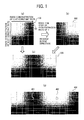
- Fig. 1(a), 1(b), 1(c), and 1(d) are diagrams illustrating a sequence of laying out color patches and color blocks in a color chart of an embodiment of the present disclosure
- Fig. 2(a), 2(b), and 2(c) are diagrams illustrating another sequence of laying out color patches and color blocks in a color chart of an embodiment of the present disclosure
- Fig. 3(a), 3(b), and 3(c) are diagrams illustrating color blocks in which a copy of a color patch row group or a color patch column group at the outermost peripheral is added to the outermost peripheral;
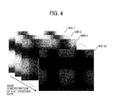
- Fig. 4 is a diagram illustrating a group of color charts with different color reproduction concentration ratio of black (K);
- Fig. 5(a) and 5(b) are diagrams illustrating color blocks in background art
- Fig. 6 is a diagram illustrating a color chart containing multiple color blocks in background art ;
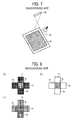
- Fig. 7 is a schematic perspective view illustrating how to read color patches on a color chart by an image pickup device for reading a wide area
- Fig. 8(a), 8(b), and 8(c) are diagrams illustrating an impact of color patches arranged around a target color patch on measuring results.
- Fig. 1 is a diagram illustrating the sequence of laying out color patches in a color chart of an embodiment of the present disclosure. The laying-out sequence of the color patches is described with reference to Fig. 1 .
- Y yellow
- M magenta
- C cyan
- K black
- color patches 101 each of which has a different combination of cyan (C) and magenta (M) made by preferably changing the level (12 levels in this case) at a fixed rate for each two colors (first color and second color) are laid out two-dimensionally (i.e., matrix) to form a color block 100.
- a color block chart 200 illustrated in Fig. 1B is made by copying the color block 100 illustrated in Fig. 1(a) and raising the ratio of the color reproduction concentration of yellow (Y) preferably one level of the fixed rate followed by reversing related to a direction, for example, the row direction or the column direction. In this embodiment, the direction is the row direction.
- a color chart 400 illustrated in Fig. 1(d) is made by copying the color chart 300 of Fig. 1(c) and the color block 100 of Fig. 1(a) , raising the ratio of the color reproduction concentration of yellow (Y) of the color block 100 two levels of the fixed rate, and synthesizing the color chart 300 with the resultant color block.
- color patches of respective color reproduction concentrations are separately made and laid out to form the color chart 300 illustrated in Fig. 1(b) and the color chart 400 of Fig. 1(d) .
- target color patches 401 and 402 illustrated in Fig. 1 (d) are taken as examples for description.
- color patches 401 and 402 are arranged color patches having slightly different color reproduction concentrations from those of the color patches 401 and 402. Therefore, when the color chart 400 is read by an image pickup device such as a scanner that can read in the two-dimensional range, the measuring results of the target color patches 401 and the 402 have just small errors.
- Fig. 2 is a diagram illustrating another sequence of forming a color chart of the embodiment.
- a desired color chart is formed by reversing and copying a single color chart.
- the sequence of forming a color chart illustrated in Fig. 2 is to conduct the following to a group of color blocks arranged vertically and the row direction in which multiple color patches are laid out in matrix to obtain a desired color chart.
- a color block 501 (enclosed by dotted lines in Fig.
- the color block group 500 illustrated in Fig. 2(a) are formed by laying out 12 color blocks by 3 rows times 4 columns.
- target color patches 701 and 702 illustrated in Fig. 2(c) are taken as examples for description.
- color patches 701 and 702 are arranged color patches having slightly different color reproduction concentrations from those of the color patches 701 and 702. Therefore, when the color chart 700 is read by an image pickup device such as a scanner that can read in the two-dimensional range, the measuring results of the target color patches 701 and the 702 have only small errors.
- the thus-obtained image data are affected by the basic color (typically white) of paper on which the color chart is output.
- the basic color typically white
- Fig. 3 at least one copy of the color patch is laid out on the outside of the color patch situated at the outermost periphery.
- two or more copied color patches can be laid out to the outside.
- a color patch column group 801 and a color patch row group 802 which are part of the outermost periphery of a color chart 800 are copied.
- the copied color patch column group 803 is laid out such that t the copied color patch column group 803 is tangent to the color patch column group 801.
- the copied color patch row group 804 is laid out such that t the copied color patch row group 804 is tangent to the color patch row group 802. Outermost processing is conducted on the memory as described above. As illustrated in Fig.
- the basic color of the paper does not affect color measuring.
- the error of the measuring value is small when the color patches having such an arrangement at the outermost peripheral in the color chart are read by an image pickup device able to read in the two dimensional range such as a scanner.
- a color chart group having multiple color charts which is formed by changing the ratio of the color reproduction concentration of an arbitrarily selected color (fourth color) from the multiple reproduction colors and further changing the ratio of the color reproduction concentration of the arbitrarily selected color from the multiple reproduction colors for each sheet.
- the reproduction colors in which the ratio of the color reproduction concentration are changed within each color chart i.e., first, second, and third colors
- the colors of the color reproduction concentration which are changed within the color chart are yellow(Y), magenta (M), and cyan (C) among YMCK and the color of the color reproduction concentration which is changed among the group of color charts is black (K).
- the color chart formed by changing the ratio of the color reproduction concentration for each color of YMC preferably with one degree of a predetermined value is shown in Fig. 2 .
- the color chart is formed as described above.
- color blocks are formed first in which the color patches are arranged in matrix according to the ratios of the color reproduction concentration of cyan (C) and magenta (M) changed by preferably level by level of a predetermined fixed rate. Then, based on the thus-formed color block, multiple color blocks are formed by changing the color reproduction concentration of the ratio of yellow (Y) level by level of a predetermined fixed rate. In this case, 12 color blocks are made.
- the color block group in which 12 color blocks are arranged is set in a single sheet to form a color chart. In the color chart, each color patch is laid out as described above such that the distribution of the color reproduction concentration for the entire layout is gentle.
- the black (K) component since the key color (fourth color) of black (K) affects all the measured RGB components, the black (K) component must be the same in the color chart. That is, the ratio of the color reproduction concentration of black (K) is changed preferably with level by level at a fixed rate among the color charts.
- the RGB components measured by the combination of the two colors change while keeping the remaining color the same to have the same influence.
- a color block is formed by changing cyan (C) and magenta (M) one degree by one degree of the 12 degrees and yellow (Y) of the color block is changing one degree by one degree of 12 degrees to obtain a color block group having 12 color blocks.
- the ratio of the black (K) is raised one degree by one degree of 12 degrees. That is, as illustrated in Fig. 4 , the ratio of the color reproduction concentration of black (K) for the color block group in each color chart is changed one degree by one degree of the predetermined value to the 12th degree to obtain a color chart group having 12 color charts of 900-1 to 900-12.
- the concentration of the corresponding ink is printed by changing color charts as in the black plate.
- color patches having different color reproduction concentration are formed by changing the color reproduction concentration of selected colors, for example, cyan (C) and magenta (M) among the four colors one degree by one degree of a predetermined ratio to, for example, 12th degree and each color patch is laid out in matrix to form the color block 100. Then, the color block 100 is copied and the ratio of the color reproduction concentration of yellow (Y) of the copied color block is changed one degree of the predetermined value. Furthermore, the color block is reversed horizontally to form the color block 200.
- selected colors for example, cyan (C) and magenta (M) among the four colors one degree by one degree of a predetermined ratio to, for example, 12th degree
- M magenta
- the color block 200 is connected to the color block 100 horizontally to synthesize the color chart 300.
- color patches having a color reproduction concentration of cyan (C) and magenta (M) close to each other are laid out in the vicinity.
- the color reproduction concentrations of all of the color patches forming such a color chart are different from each other, thereby not reducing the number of the target color patches that can be output on paper.
- multiple color patches having a different color reproduction concentration of the first and the second colors from each other are formed and laid out in matrix to obtain a color block.
- Such color blocks having different color reproduction with regard to the third color are arranged to form the color chart 500 temporarily.
- the even columns of the color block are reversed relative to the row direction and the even rows of the color block row groups 502 are reversed relative to the column direction to form the color chart 700.
- color charts 700 color patches having a color reproduction concentration close to each other with regard to the two colors among the four colors are laid out.
- the color reproduction concentrations of all the color patches forming the color chart are different from each other. Therefore, the color patches output on paper are subjected to measuring and do not include the one laid out only to reduce an error as in typical techniques. Therefore, the number of the target color patches that can be output on paper does not decrease.
- the color patches at the outermost peripheral of the color block 800 is affected by the reflected light from the basic color of the paper.
- at least one color patch at the outermost peripheral is copied and the copy of the color patch is laid out to the outside of the color patch. Therefore, when the color patch at the outermost peripheral is subjected to measuring by an image pickup device such as a scanner able to read a two dimensional range, the error of the measuring result of the color concentration is small because the copy of the color patch having the same concentration as the color patch is laid out in the vicinity thereof,
Landscapes
- Physics & Mathematics (AREA)
- Spectroscopy & Molecular Physics (AREA)
- Engineering & Computer Science (AREA)
- Multimedia (AREA)
- Signal Processing (AREA)
- General Physics & Mathematics (AREA)
- Facsimile Image Signal Circuits (AREA)
- Color Image Communication Systems (AREA)
Abstract
Description
- The present invention relates to a color chart.
- In recent years, image forming apparatuses employing electrophotography and an ink jet recording system have come to be used in the field of on-demand printing. Yet even users in the field of the quick printing (on-demand printing) demand high quality production from such image forming apparatuses. To meet that demand, manufacturers adjust product quality, in particular color reproduction concentration, at shipment.
- In addition, image quality is also affected by the course of time, environmental changes, changes in characteristics of developing agents, etc., due to usage conditions thereof, and usage of paper having different characteristics. Consequently, users also must adjust color reproduction concentration to maintain the quality of images for such changes over time, environmental changes, and characteristic changes.
- Image forming apparatuses employing electrophotography convert image data formed of the colors red (R), green (G), and blue (B) image data or cyan (C), magenta (M), yellow (Y), and black (K) into reproducible colors according to color reproduction models in the apparatuses. Images are formed on recording media using image forming materials such as toner and ink constituted of, for example, the colors yellow, magenta, cyan, and black. The color conversion described above is conducted by using color conversion profiles stored in the image forming apparatuses. The color conversion profiles are made based on a color reproduction model at the stages of designing, manufacturing, and shipment. That color reproduction model indicates the range of colors reproducible by an image forming apparatus and is expressed as a characteristic diagram of three axes of X, Y, and Z, mapping intensity, saturation, and color phase, respectively. A simpler color reproduction model can be provided in which colors are expressed using saturation for the X axis and intensity for the Y axis.
- A color chart is another color reproduction model in which color patches representing colors reproducible by an image forming apparatus are arranged. The color chart is output by an image forming apparatus and measured by a colorimeter to make the color conversion profile described above.
- Naturally, the range of reproducible colors of an image forming apparatus subjected to color reproduction concentration adjustment depends on the color chart serving as the color reproduction model.
- The reproduction colors of the color patches forming the color chart are expressed as predetermined pile heights. The pile height is the total of the physical amount of an image forming material formed of, for example, yellow, cyan, magenta, and black in proportion to the color reproduction concentration of the four colors.
- Therefore, the reproducible colors of the color patch are expressed as the total of the physical amount in proportion to the color reproduction concentration of the four colors.
-
Fig. 5 is a diagram illustrating one of multiple color blocks forming a typically used color chart. Acolor block 10 illustrated inFig. 5(a) includes color patches 11 arranged in a matrix (of 12 x 12 patches in this example) which have different color reproduction concentrations formed by increasing the color reproduction concentrations of cyan (C) and magenta (M) (from among cyan (C), magenta (M), yellow (Y), and black (K)) at a fixed rate. - In
Fig. 5(a) , the ratio of the color reproduction concentration of each of yellow (Y) and black (K) is 0 %. - While the color reproduction concentration of one of the two colors selected from the four colors is kept constant, color patches are formed by increasing the color reproduction concentration of the other color of the selected two at a fixed rate and arranged vertically or the row direction.
- For example, the
color block 10 illustrated inFig. 5A is constituted according to the following layout procedure of multiple color patches 11. A colorpatch column group 12 is formed by sequentially laying out multiple color patches 11 formed by increasing the color reproduction concentration of magenta (M) vertically at a fixed rate while the color reproduction concentration of cyan (C) is kept unchanged at a predetermined ratio. - The color
patch column group 12 is copied horizontally while increasing the color reproduction concentration of cyan (C) at a predetermined fixed rate. This is repeated while increasing the level of the predetermined fixed rate one by one until the thus-formed multiple copied color patch column groups with different levels of color reproduction concentration are laid out horizontally (from left to right inFig. 5(a) ) according to the color reproduction concentration to obtain thecolor block 10. - A color
patch row group 13 is formed by sequentially laying out multiple color patches 11 formed by increasing the color reproduction concentration of cyan (C) level by level at a fixed rate while the color reproduction concentration of cyan (M) is kept at a predetermined color reproduction concentration unchanged. The colorpatch row group 13 is copied vertically while increasing the color reproduction concentration of cyan (M) one level of a predetermined fixed rate. This is repeated while increasing the level of the predetermined fixed rate one by one until the thus-formed multiple copied color patch row groups with different levels of the fixed rate of color reproduction concentration are laid out vertically (from top to bottom inFig. 5(a) ) according to the color reproduction concentration to obtain thecolor block 10. - To the
color block 10 ofFig. 5(a) , in which the ratio of the color reproduction concentration of yellow (Y) and black (K) to the total of the color reproduction concentration of the four colors is zero, the ratio of the color reproduction concentration of yellow (Y) is raised one level of a predetermined fixed rate for all the color patches 11 in thecolor block 10 to obtain acolor block 20 illustrated inFig. 5(b) . The ratio of color reproduction concentration of black (K) to the color reproduction concentration of the colors is still kept at 0 %. Then, other color blocks having different color reproduction concentrations of yellow (Y) are repeatedly formed as described above until all the color blocks laid out as inFig. 6 (fourcolor blocks Fig. 6 ). Thereafter, thecolor blocks Fig. 6 are output on the surface of recording paper serving as an output medium to form acolor chart 50. To be specific, thecolor block 20 is laid out adjacent to thecolor block 10 horizontally. - The
color block 30 is laid out not adjacent to thecolor block 20 horizontally but to thecolor block 10 vertically if it cannot be output on the surface of the recording paper because of the size of the surface as illustrated inFig. 6 . Furthermore, thecolor block 40 is laid out adjacent to thecolor block 30 horizontally. As a result, it can be seen that, in thecolor chart 50 having such an arrangement, for example, the concentration difference between a color patch 51-1 and a color patch 51-2 laid out adjacent to the color patch 51-1 horizontally is extremely large, as illustrated inFig. 6 . The implications of this large difference are explained below. - Next, the color reproduction concentration in the image forming apparatus using the
color chart 50 output must be adjusted. First, a color patch, for example, the color patch 51-1 in the reading spot indicated by broken lines inFig. 6 , is read by a colorimeter, which is a device that irradiates a reading target with light and receives only reflected light therefrom to output image data. Then, a higher-level device temporarily stores the read image data and compares them with reference data of the color patch present corresponding to the arrangement in the color chart preliminarily stored in a memory table. The color reproduction concentration in the target image forming apparatus is adjusted based on this comparison result. - However, as described above, when image data expressed as RGB color space is color-converted into and expressed as YMCK on the output side, the combination of RGB is 256 x 256 x 256, which is about 16,700,000 if one color has 256 gradations. Such a large combination of colors requires a number of sheets to obtain a printed color chart shown in
Fig. 6 . - In such a case, reading each of color patches by a colorimeter while focusing beams of light thereon takes an extremely long time to complete reading. To make the color reading time short, it is conceivable to reduce the number of the gradations and combinations. However, the color reproduction concentration distribution of each arranged color patch is rough, which results in a large adjustment error of the color reproduction concentration. Therefore, drastically reducing the number of gradations and combinations is not desirable.
- In an attempt to shorten the time taken for color measuring, Japanese patent application publication no.
2001-088357 JP-2001-088357-A JP-2001-088357-A Fig. 8(a) , among YMCK of atarget color patch 70 in part of the color chart, if the color reproduction concentration of, for example, cyan (C) of thetarget color patch 70 is much lower than those of thecolor patches 71 to 74 laid out adjacent to thetarget color patch 70, those color patches are read by a two-dimension scanning-type image pickup. In addition, as illustrated inFig. 8(b) , even when the color reproduction concentrations of cyan (C) of thecolor patches 71 to 74 are zero, those color patches are read by the two-dimension scanning-type image pickup. - These drawbacks stem from the scanning method of a scanner in which the reflected light of the color patches and paper around a target color patch is read as well as the reflected light from the target color patch irradiated with light in the two-dimensional range. Therefore, as illustrated in
Fig. 8(c) , by making the color reproduction concentration of, for example, cyan (C) among YMCK of thetarget color patch 70 same as those of thecolor patches 71 to 74 around thetarget color patch 70, the concentration components in the measuring data are the same or significantly close to each other if the reflected light from thecolor patches 71 to 74 in the two-dimensional range is taken in. Therefore, the image data of thetarget color patch 70 are much less affected. - However, the area of the same color significantly increases by laying out color patches having the same color around the target color patch, which in turn greatly decreases the number of target color patches in the color chart output on paper.
- In view of the foregoing, the present invention provides an improved color chart having a plurality of mirror-image color blocks arranged in a matrix, with each color block a mirror image of an adjacent color block, each color block having rows and columns of color patches, wherein the concentration of a first color of the multiple colors changes unidirectionally across color patches in any given row of each color block, the concentration of a second color of the multiple colors changes unidirectionally across color patches in any given column of a color block, and the concentration of a third color of the multiple colors remains unchanged across all the plurality of mirror-image color patches within a color block and differs only between color blocks.
- It is preferred that, in the color chart mentioned above, the concentration of the first color of the rows of color patches changes in discrete levels at a fixed rate.
- It is still further preferred that, in the color chart mentioned above, the concentration of the second color of the columns of color patches changes in discrete levels at a fixed rate.
- It is still further preferred that, in the color chart mentioned above, the concentration of the third color of differs between adjacent color blocks in discrete levels at a fixed rate
- As another aspect of the present invention, a group of color charts is provided which includes a plurality of the color charts mentioned above, wherein the concentration of a fourth color of the multiple colors differs between color charts.
- It is preferred that, in the group of color charts mentioned above, the concentration of the fourth color among the plurality of the color charts changes in discrete levels at a fixed rate.
- As another aspect of the present invention, an image forming apparatus that generates the color chart mentioned above for use in color reproduction concentration adjustment is provided which includes a memory unit that saves image data of a first color block and a processor that reverses the first color block to form a second mirror image of the first color block to form the color chart.
-
Fig. 1(a), 1(b), 1(c), and 1(d) are diagrams illustrating a sequence of laying out color patches and color blocks in a color chart of an embodiment of the present disclosure; -
Fig. 2(a), 2(b), and 2(c) are diagrams illustrating another sequence of laying out color patches and color blocks in a color chart of an embodiment of the present disclosure; -
Fig. 3(a), 3(b), and 3(c) are diagrams illustrating color blocks in which a copy of a color patch row group or a color patch column group at the outermost peripheral is added to the outermost peripheral; -
Fig. 4 is a diagram illustrating a group of color charts with different color reproduction concentration ratio of black (K); -
Fig. 5(a) and 5(b) are diagrams illustrating color blocks in background art; -
Fig. 6 is a diagram illustrating a color chart containing multiple color blocks in background art ; -
Fig. 7 is a schematic perspective view illustrating how to read color patches on a color chart by an image pickup device for reading a wide area; and -
Fig. 8(a), 8(b), and 8(c) are diagrams illustrating an impact of color patches arranged around a target color patch on measuring results. - When measuring a target color patch affected by color patches therearound, which includes the color patches having a color and brightness greatly different from those of the target color patch, the measuring values of the target color patch significantly vary. Therefore, if color patches having a color close to that of a target color patch are arranged therearound, the error of the measuring results can be reduced. The sequence of forming a color chart in which such color patches are laid out is described below.
-
Fig. 1 is a diagram illustrating the sequence of laying out color patches in a color chart of an embodiment of the present disclosure. The laying-out sequence of the color patches is described with reference toFig. 1 . First, select two changing colors (first color and second color) from the four colors of yellow (Y), magenta (M), cyan (C), and black (K). In this case, cyan (C) and magenta (M) are selected as the changing colors. As illustrated inFig. 1(a) ,color patches 101 each of which has a different combination of cyan (C) and magenta (M) made by preferably changing the level (12 levels in this case) at a fixed rate for each two colors (first color and second color) are laid out two-dimensionally (i.e., matrix) to form acolor block 100. Next, acolor block chart 200 illustrated inFig. 1B is made by copying thecolor block 100 illustrated inFig. 1(a) and raising the ratio of the color reproduction concentration of yellow (Y) preferably one level of the fixed rate followed by reversing related to a direction, for example, the row direction or the column direction. In this embodiment, the direction is the row direction. Acolor chart 300 ofFig. 1(c) is synthesized by connecting thecolor block 100 ofFig. 1(a) with thecolor block 200 ofFig. 1(b) along the row direction. To be specific, the image data of thecolor block 100 is saved in a memory and reversed by the mirror reversing processing on the memory to obtain the image data for thecolor block 200 followed by increasing the color reproduction concentration of yellow (Y) (third color). Thereafter, the image data of thecolor block 100 and the image data of thecolor block 200 are synthesized on the memory to obtain the image data of thecolor chart 300. Furthermore, acolor chart 400 illustrated inFig. 1(d) is made by copying thecolor chart 300 ofFig. 1(c) and thecolor block 100 ofFig. 1(a) , raising the ratio of the color reproduction concentration of yellow (Y) of thecolor block 100 two levels of the fixed rate, and synthesizing thecolor chart 300 with the resultant color block. - Alternatively, color patches of respective color reproduction concentrations are separately made and laid out to form the
color chart 300 illustrated inFig. 1(b) and thecolor chart 400 ofFig. 1(d) . - In the
color chart 400, for example,target color patches Fig. 1 (d) are taken as examples for description. Around thecolor patches color patches color chart 400 is read by an image pickup device such as a scanner that can read in the two-dimensional range, the measuring results of thetarget color patches 401 and the 402 have just small errors. - It is possible to conduct a reversing process according to the layout of target color patches and not necessary to conduct reversing all as illustrated in
Fig. 1 . -
Fig. 2 is a diagram illustrating another sequence of forming a color chart of the embodiment. InFig. 1 , a desired color chart is formed by reversing and copying a single color chart. The sequence of forming a color chart illustrated inFig. 2 is to conduct the following to a group of color blocks arranged vertically and the row direction in which multiple color patches are laid out in matrix to obtain a desired color chart. As illustrated inFig. 2(a) , to a color block 501 (enclosed by dotted lines inFig. 2(a) ) in which color patches of different combinations of cyan (c) and magenta (m) formed by changing the color reproduction concentrations of the two colors preferably level by level of respective fixed rates are laid out in matrix, The ratio of the color reproduction concentration of yellow (Y) is raised preferably in discreet levels at a fixed rate to form other color blocks and the resultant color blocks are laid out horizontally (a color block row group 502) and the column direction to form (color block column group 503). - That is, the
color block group 500 illustrated inFig. 2(a) are formed by laying out 12 color blocks by 3 rows times 4 columns. - Then, the even columns of the
color block group 500 relative to the vertical direction, the second and the fourth columns of thecolor block group 500 inFig. 2(a) are reversed to obtain acolor block group 600 as illustrated inFig. 2(b) . Furthermore, the even row of thecolor block 600, i.e., the second row of the color block row group, is reversed vertically, a desired chart of acolor chart 700 illustrated inFig. 2(c) is formed. The process of laying out each color patch to form a specific color chart is conducted on the memory as described above. - In the
color chart 700, for example,target color patches Fig. 2(c) are taken as examples for description. Around thecolor patches color patches color chart 700 is read by an image pickup device such as a scanner that can read in the two-dimensional range, the measuring results of thetarget color patches 701 and the 702 have only small errors. - It is possible to conduct a reversing process according to the layout of target color patches and not necessary to conduct reversing all as illustrated in
Fig. 2 . - When the color patches situated at the outermost periphery of the color charts formed by the sequence of laying out color patches described above are read by, for example, a two-dimensional scanner, the thus-obtained image data are affected by the basic color (typically white) of paper on which the color chart is output. As illustrated in
Fig. 3 , at least one copy of the color patch is laid out on the outside of the color patch situated at the outermost periphery. Depending on the reading performance of the scanner, for example, when a high-performance scanner is used and the measuring values of the color patch situated at the outermost periphery is affected by the basic color of paper, two or more copied color patches can be laid out to the outside. Therefore, all the color patches including the one situated at the outermost periphery are surrounded by color patches having the same color or close color. To be specific, as illustrated inFig. 3(b) , a colorpatch column group 801 and a colorpatch row group 802 which are part of the outermost periphery of acolor chart 800 are copied. Then, as illustrated inFig. 3B , the copied colorpatch column group 803 is laid out such that t the copied colorpatch column group 803 is tangent to the colorpatch column group 801. In addition, the copied colorpatch row group 804 is laid out such that t the copied colorpatch row group 804 is tangent to the colorpatch row group 802. Outermost processing is conducted on the memory as described above. As illustrated inFig. 3(c) , by copying the color patch column group and the color patch row group at the outermost peripheral, for example, in the case of thetarget color patch 805 in the color patch column group at the outermost peripheral and thetarget color patch 806 in the colorpatch row group 802 at the outermost peripheral, color patches having the same colors as thecolor patches - Therefore, the basic color of the paper does not affect color measuring. The error of the measuring value is small when the color patches having such an arrangement at the outermost peripheral in the color chart are read by an image pickup device able to read in the two dimensional range such as a scanner. Variation
- Next, as a variation of the embodiment described above, a color chart group having multiple color charts is described which is formed by changing the ratio of the color reproduction concentration of an arbitrarily selected color (fourth color) from the multiple reproduction colors and further changing the ratio of the color reproduction concentration of the arbitrarily selected color from the multiple reproduction colors for each sheet.
- First, the reproduction colors in which the ratio of the color reproduction concentration are changed within each color chart (i.e., first, second, and third colors) of the group of color charts and among the color charts (fourth color) are preliminarily determined. In this embodiment, the colors of the color reproduction concentration which are changed within the color chart are yellow(Y), magenta (M), and cyan (C) among YMCK and the color of the color reproduction concentration which is changed among the group of color charts is black (K). The color chart formed by changing the ratio of the color reproduction concentration for each color of YMC preferably with one degree of a predetermined value is shown in
Fig. 2 . The color chart is formed as described above. That is, color blocks are formed first in which the color patches are arranged in matrix according to the ratios of the color reproduction concentration of cyan (C) and magenta (M) changed by preferably level by level of a predetermined fixed rate. Then, based on the thus-formed color block, multiple color blocks are formed by changing the color reproduction concentration of the ratio of yellow (Y) level by level of a predetermined fixed rate. In this case, 12 color blocks are made. The color block group in which 12 color blocks are arranged is set in a single sheet to form a color chart. In the color chart, each color patch is laid out as described above such that the distribution of the color reproduction concentration for the entire layout is gentle. Next, since the key color (fourth color) of black (K) affects all the measured RGB components, the black (K) component must be the same in the color chart. That is, the ratio of the color reproduction concentration of black (K) is changed preferably with level by level at a fixed rate among the color charts. With regard to the combination of the three rest colors, the RGB components measured by the combination of the two colors change while keeping the remaining color the same to have the same influence. For example, a color block is formed by changing cyan (C) and magenta (M) one degree by one degree of the 12 degrees and yellow (Y) of the color block is changing one degree by one degree of 12 degrees to obtain a color block group having 12 color blocks. Then, the ratio of the black (K) is raised one degree by one degree of 12 degrees. That is, as illustrated inFig. 4 , the ratio of the color reproduction concentration of black (K) for the color block group in each color chart is changed one degree by one degree of the predetermined value to the 12th degree to obtain a color chart group having 12 color charts of 900-1 to 900-12. - Thereby, as in the case of the ink plate affected like the RGB component of a scanner such as reproduction color of transparent ink or gray ink, the concentration of the corresponding ink is printed by changing color charts as in the black plate.
- As described above, according to the embodiments, as illustrated in
Fig. 1 , color patches having different color reproduction concentration are formed by changing the color reproduction concentration of selected colors, for example, cyan (C) and magenta (M) among the four colors one degree by one degree of a predetermined ratio to, for example, 12th degree and each color patch is laid out in matrix to form thecolor block 100. Then, thecolor block 100 is copied and the ratio of the color reproduction concentration of yellow (Y) of the copied color block is changed one degree of the predetermined value. Furthermore, the color block is reversed horizontally to form thecolor block 200. - Thereafter, the
color block 200 is connected to thecolor block 100 horizontally to synthesize thecolor chart 300. In the thus-arrangedcolor chart 300, color patches having a color reproduction concentration of cyan (C) and magenta (M) close to each other are laid out in the vicinity. - When the thus-obtained color chart is read by an image pickup device able to read a two dimensional range such as a scanner, the error of the measuring result of the color concentration is small.
- In addition, the color reproduction concentrations of all of the color patches forming such a color chart are different from each other, thereby not reducing the number of the target color patches that can be output on paper.
- In addition, according to the embodiments, as illustrated in
Fig. 2 , multiple color patches having a different color reproduction concentration of the first and the second colors from each other are formed and laid out in matrix to obtain a color block. Such color blocks having different color reproduction with regard to the third color are arranged to form thecolor chart 500 temporarily. - The even columns of the color block are reversed relative to the row direction and the even rows of the color
block row groups 502 are reversed relative to the column direction to form thecolor chart 700. In the thus-arrangedcolor chart 700, color patches having a color reproduction concentration close to each other with regard to the two colors among the four colors are laid out. - When the thus-arranged color chart is read by an image pickup device able to read in the two dimensional range such as a scanner, the error of the measuring result of the color concentration is small.
- In addition, the color reproduction concentrations of all the color patches forming the color chart are different from each other. Therefore, the color patches output on paper are subjected to measuring and do not include the one laid out only to reduce an error as in typical techniques. Therefore, the number of the target color patches that can be output on paper does not decrease.
- Furthermore, according to the embodiments, the color patches at the outermost peripheral of the
color block 800 is affected by the reflected light from the basic color of the paper. To reduce this impact, at least one color patch at the outermost peripheral is copied and the copy of the color patch is laid out to the outside of the color patch. Therefore, when the color patch at the outermost peripheral is subjected to measuring by an image pickup device such as a scanner able to read a two dimensional range, the error of the measuring result of the color concentration is small because the copy of the color patch having the same concentration as the color patch is laid out in the vicinity thereof, - In addition, according to the embodiments, as illustrated in
Fig. 4 , the ratio of the color reproduction concentration of the remaining reproduction color in one color chart in which the ratio of the color reproduction concentration of the reproduction colors is changed one degree by one degree with a particular fixed value to, for example, the 12th degree. Those makes a group of color chart having 12 color charts of 900-1 to 900-12 having different color reproduction concentrations of color reproduction. - When the group of the 12 color charts is read by an image pickup device such as a scanner able to read a two dimensional range, the error of the measuring result of the color concentration is small.
Claims (7)
- A color chart comprising:a plurality of mirror-image color blocks arranged in a matrix, with each color block a mirror image of an adjacent color block,each color block comprising rows and columns of color patches, wherein:a concentration of a first color of the multiple colors changes unidirectionally across color patches in any given row of a color block;a concentration of a second color of the multiple colors changes unidirectionally across color patches in any given column of a color block; anda concentration of a third color of the multiple colors remains unchanged across all the plurality of color patches within a color block and differs only between color blocks.
- The color chart according to Claim 1, wherein the concentration of the first color of the rows of color patches changes in discrete levels at a fixed rate.
- The color chart according to Claim 1 or 2, wherein the concentration of the second color of the columns of color patches changes in discrete levels at a fixed rate.
- The color chart according to any one of Claims 1 to 3, wherein the concentration of the third color of differs between adjacent color blocks in discrete levels at a fixed rate.
- A group of color charts comprising:a plurality of the color charts of any one of Claims 1 to 4,wherein a concentration of a fourth color of the multiple colors differs between color charts.
- The group of color charts according to Claim 5, wherein the concentration of the fourth color among the plurality of the color charts changes in discrete levels at a fixed rate.
- An image forming apparatus comprising that generates the color chart of any one of Claims 1 to 6 for use in color reproduction concentration adjustment:a memory unit that saves image data of a first color block; anda processor that reverses the first color block to form a second mirror image of the first color block to form the color chart.
Applications Claiming Priority (2)
| Application Number | Priority Date | Filing Date | Title |
|---|---|---|---|
| JP2010287094 | 2010-12-24 | ||
| JP2011113569A JP5880997B2 (en) | 2010-12-24 | 2011-05-20 | Color chart and color chart creation method |
Publications (2)
| Publication Number | Publication Date |
|---|---|
| EP2469836A1 true EP2469836A1 (en) | 2012-06-27 |
| EP2469836B1 EP2469836B1 (en) | 2016-03-02 |
Family
ID=45524265
Family Applications (1)
| Application Number | Title | Priority Date | Filing Date |
|---|---|---|---|
| EP11195399.8A Active EP2469836B1 (en) | 2010-12-24 | 2011-12-22 | Color chart |
Country Status (3)
| Country | Link |
|---|---|
| US (1) | US8649020B2 (en) |
| EP (1) | EP2469836B1 (en) |
| JP (1) | JP5880997B2 (en) |
Families Citing this family (8)
| Publication number | Priority date | Publication date | Assignee | Title |
|---|---|---|---|---|
| JP6503747B2 (en) * | 2015-01-15 | 2019-04-24 | コニカミノルタ株式会社 | Color correction chart creation control program, image forming apparatus, and color correction chart creation method |
| JP6897361B2 (en) | 2017-06-22 | 2021-06-30 | セイコーエプソン株式会社 | Color chart for color selection, color chart generation method for color selection, color chart generation program for color selection, and color chart generation device for color selection |
| JP6947060B2 (en) | 2018-01-31 | 2021-10-13 | 株式会社リコー | Image processing equipment, image processing methods and programs |
| JP7487568B2 (en) | 2020-06-04 | 2024-05-21 | 株式会社リコー | Image inspection device, display method and program |
| JP2022014759A (en) | 2020-07-07 | 2022-01-20 | 株式会社リコー | Image processing equipment, image processing system, image processing method, and image processing program |
| JP7512723B2 (en) | 2020-07-08 | 2024-07-09 | 株式会社リコー | Image processing device, method, and system |
| JP7618994B2 (en) | 2020-10-06 | 2025-01-22 | 株式会社リコー | Image forming device |
| US11934713B2 (en) | 2022-05-02 | 2024-03-19 | Ricoh Company, Ltd. | Image forming system, inspection device, and inspection method |
Citations (2)
| Publication number | Priority date | Publication date | Assignee | Title |
|---|---|---|---|---|
| JP2001088357A (en) | 1999-09-22 | 2001-04-03 | Ricoh Co Ltd | Color image recording device |
| EP1187464A2 (en) * | 2000-09-12 | 2002-03-13 | Canon Kabushiki Kaisha | Image processing apparatus and its control method, and image processing method |
Family Cites Families (19)
| Publication number | Priority date | Publication date | Assignee | Title |
|---|---|---|---|---|
| US4719506A (en) * | 1983-09-30 | 1988-01-12 | Buren Keith E Van | Method for predictably determining halftone dot sizes when altering color in a color separation process prior to scanning |
| JPH10322555A (en) | 1997-05-20 | 1998-12-04 | Ricoh Co Ltd | Image forming device |
| JP2002027272A (en) * | 2000-07-11 | 2002-01-25 | Fuji Photo Film Co Ltd | Color chart and method for preparing color conversion definition |
| JP3779868B2 (en) * | 2000-09-13 | 2006-05-31 | サカタインクス株式会社 | Color chart creation method and color chart |
| JP3689325B2 (en) | 2000-10-31 | 2005-08-31 | 富士写真フイルム株式会社 | Color reproduction characteristics correction method |
| JP2003111108A (en) | 2001-09-27 | 2003-04-11 | Fuji Photo Film Co Ltd | Chart for evaluating imaging system and its forming method |
| JP2003289446A (en) | 2002-03-28 | 2003-10-10 | Fuji Photo Film Co Ltd | Method, apparatus and program for providing color reproduction characteristic |
| JP3768960B2 (en) * | 2003-01-14 | 2006-04-19 | 見本合成樹脂株式会社 | Coloring method and transaction document and color chart with color space using the same |
| US7233398B2 (en) * | 2003-05-29 | 2007-06-19 | Konica Minolta Medical & Graphic, Inc. | Colorimeter measured value control system and colorimeter measured value control method thereof, and a color control information providing system and a color control information providing method thereof |
| JP4406229B2 (en) * | 2003-07-28 | 2010-01-27 | Hoya株式会社 | Color chart for color adjustment of color printer and color monitor in endoscope |
| JP4231359B2 (en) * | 2003-07-28 | 2009-02-25 | Hoya株式会社 | Color chart for color adjustment of color printers and color monitors in endoscopes |
| JP4272972B2 (en) * | 2003-10-23 | 2009-06-03 | Hoya株式会社 | Color chart for color adjustment and gradation adjustment of color printers and color monitors in endoscopes |
| JP2005229371A (en) | 2004-02-13 | 2005-08-25 | Seiko Epson Corp | Printing profile setting device, printing profile setting system, printing profile setting method, and printing profile setting program |
| JP4337592B2 (en) | 2004-03-22 | 2009-09-30 | 富士ゼロックス株式会社 | Profile creation apparatus, profile creation method, recording medium, and program |
| JP4539458B2 (en) * | 2005-06-24 | 2010-09-08 | 富士ゼロックス株式会社 | Image forming apparatus |
| JP2007214625A (en) * | 2006-02-07 | 2007-08-23 | Fuji Xerox Co Ltd | Image processor |
| JP2009192463A (en) | 2008-02-18 | 2009-08-27 | Seiko Epson Corp | Test chart and color calibration method |
| JP4618457B2 (en) * | 2008-06-16 | 2011-01-26 | 富士ゼロックス株式会社 | Color signal processing device, color conversion device, color signal processing program, color conversion program |
| JP5186457B2 (en) * | 2009-09-14 | 2013-04-17 | 富士フイルム株式会社 | Colorimetric value calculation method, profile generation method, color conversion method, apparatus and program thereof |
-
2011
- 2011-05-20 JP JP2011113569A patent/JP5880997B2/en active Active
- 2011-12-21 US US13/332,811 patent/US8649020B2/en active Active
- 2011-12-22 EP EP11195399.8A patent/EP2469836B1/en active Active
Patent Citations (2)
| Publication number | Priority date | Publication date | Assignee | Title |
|---|---|---|---|---|
| JP2001088357A (en) | 1999-09-22 | 2001-04-03 | Ricoh Co Ltd | Color image recording device |
| EP1187464A2 (en) * | 2000-09-12 | 2002-03-13 | Canon Kabushiki Kaisha | Image processing apparatus and its control method, and image processing method |
Non-Patent Citations (2)
| Title |
|---|
| HUTCHCOLOR LLC: "HCT User Guide", November 2008 (2008-11-01), XP002672049, Retrieved from the Internet <URL:http://www.hutchcolor.com/PDF/User_Guide.pdf> [retrieved on 20120321] * |
| MARK H. MCCORMICK-GOODHART: "An Introduction to the I* Metric", 24 July 2007 (2007-07-24), XP002672048, Retrieved from the Internet <URL:http://www.aardenburg-imaging.com/cgi-bin/mrk/_4605ZGxkLzBeMTAwMDAwMDAwMTIzNDU2Nzg5LyoxMQ==> [retrieved on 20120321] * |
Also Published As
| Publication number | Publication date |
|---|---|
| US20120162649A1 (en) | 2012-06-28 |
| JP2012147411A (en) | 2012-08-02 |
| US8649020B2 (en) | 2014-02-11 |
| JP5880997B2 (en) | 2016-03-09 |
| EP2469836B1 (en) | 2016-03-02 |
Similar Documents
| Publication | Publication Date | Title |
|---|---|---|
| EP2469836B1 (en) | Color chart | |
| US5537516A (en) | Method for calibrating a color printer using a scanner for color measurements | |
| US7706604B2 (en) | Production of color conversion profile for printing | |
| EP2629978B1 (en) | Image processing apparatus and image processing method | |
| US8339674B2 (en) | Halftone independent correction of spatial non-uniformities | |
| CN102729611B (en) | Method for the grey balance correction of typography | |
| US11758074B2 (en) | Color uniformity compensation mechanism | |
| US9204015B2 (en) | Image processing apparatus and image processing method | |
| JP2004181965A (en) | Whole range mapping of color using cost function | |
| JP2002094828A (en) | Edge enhancement of gray level image | |
| US8947738B2 (en) | Image processing apparatus and method for reducing coloring between color ink and clear ink on a pixel region | |
| US5130820A (en) | Image processing device | |
| EP2899964A2 (en) | Method for generating lookup table and color conversion device | |
| US11734536B2 (en) | Color uniformity compensation mechanism | |
| US7864364B2 (en) | Color correction of images | |
| US7748810B2 (en) | Image processing device, calibration table generator, image processing method, program product, and test pattern | |
| US7719716B2 (en) | Scanner characterization for printer calibration | |
| US8610977B2 (en) | Color target authenticated using grayscale information | |
| US11310393B2 (en) | Clustering colors for halftoning | |
| JP2022050987A (en) | Image processing equipment, image processing methods and programs | |
| TWI419546B (en) | Multi-function peripheral and method of generating printing data |
Legal Events
| Date | Code | Title | Description |
|---|---|---|---|
| 17P | Request for examination filed |
Effective date: 20111222 |
|
| AK | Designated contracting states |
Kind code of ref document: A1 Designated state(s): AL AT BE BG CH CY CZ DE DK EE ES FI FR GB GR HR HU IE IS IT LI LT LU LV MC MK MT NL NO PL PT RO RS SE SI SK SM TR |
|
| AX | Request for extension of the european patent |
Extension state: BA ME |
|
| PUAI | Public reference made under article 153(3) epc to a published international application that has entered the european phase |
Free format text: ORIGINAL CODE: 0009012 |
|
| 17Q | First examination report despatched |
Effective date: 20140616 |
|
| GRAP | Despatch of communication of intention to grant a patent |
Free format text: ORIGINAL CODE: EPIDOSNIGR1 |
|
| INTG | Intention to grant announced |
Effective date: 20150813 |
|
| GRAS | Grant fee paid |
Free format text: ORIGINAL CODE: EPIDOSNIGR3 |
|
| GRAA | (expected) grant |
Free format text: ORIGINAL CODE: 0009210 |
|
| AK | Designated contracting states |
Kind code of ref document: B1 Designated state(s): AL AT BE BG CH CY CZ DE DK EE ES FI FR GB GR HR HU IE IS IT LI LT LU LV MC MK MT NL NO PL PT RO RS SE SI SK SM TR |
|
| REG | Reference to a national code |
Ref country code: GB Ref legal event code: FG4D |
|
| REG | Reference to a national code |
Ref country code: AT Ref legal event code: REF Ref document number: 778687 Country of ref document: AT Kind code of ref document: T Effective date: 20160315 Ref country code: CH Ref legal event code: EP |
|
| REG | Reference to a national code |
Ref country code: IE Ref legal event code: FG4D |
|
| REG | Reference to a national code |
Ref country code: DE Ref legal event code: R096 Ref document number: 602011023595 Country of ref document: DE |
|
| REG | Reference to a national code |
Ref country code: NL Ref legal event code: MP Effective date: 20160302 |
|
| REG | Reference to a national code |
Ref country code: LT Ref legal event code: MG4D |
|
| REG | Reference to a national code |
Ref country code: AT Ref legal event code: MK05 Ref document number: 778687 Country of ref document: AT Kind code of ref document: T Effective date: 20160302 |
|
| PG25 | Lapsed in a contracting state [announced via postgrant information from national office to epo] |
Ref country code: NO Free format text: LAPSE BECAUSE OF FAILURE TO SUBMIT A TRANSLATION OF THE DESCRIPTION OR TO PAY THE FEE WITHIN THE PRESCRIBED TIME-LIMIT Effective date: 20160602 Ref country code: HR Free format text: LAPSE BECAUSE OF FAILURE TO SUBMIT A TRANSLATION OF THE DESCRIPTION OR TO PAY THE FEE WITHIN THE PRESCRIBED TIME-LIMIT Effective date: 20160302 Ref country code: ES Free format text: LAPSE BECAUSE OF FAILURE TO SUBMIT A TRANSLATION OF THE DESCRIPTION OR TO PAY THE FEE WITHIN THE PRESCRIBED TIME-LIMIT Effective date: 20160302 Ref country code: GR Free format text: LAPSE BECAUSE OF FAILURE TO SUBMIT A TRANSLATION OF THE DESCRIPTION OR TO PAY THE FEE WITHIN THE PRESCRIBED TIME-LIMIT Effective date: 20160603 Ref country code: FI Free format text: LAPSE BECAUSE OF FAILURE TO SUBMIT A TRANSLATION OF THE DESCRIPTION OR TO PAY THE FEE WITHIN THE PRESCRIBED TIME-LIMIT Effective date: 20160302 |
|
| PG25 | Lapsed in a contracting state [announced via postgrant information from national office to epo] |
Ref country code: LT Free format text: LAPSE BECAUSE OF FAILURE TO SUBMIT A TRANSLATION OF THE DESCRIPTION OR TO PAY THE FEE WITHIN THE PRESCRIBED TIME-LIMIT Effective date: 20160302 Ref country code: PL Free format text: LAPSE BECAUSE OF FAILURE TO SUBMIT A TRANSLATION OF THE DESCRIPTION OR TO PAY THE FEE WITHIN THE PRESCRIBED TIME-LIMIT Effective date: 20160302 Ref country code: AT Free format text: LAPSE BECAUSE OF FAILURE TO SUBMIT A TRANSLATION OF THE DESCRIPTION OR TO PAY THE FEE WITHIN THE PRESCRIBED TIME-LIMIT Effective date: 20160302 Ref country code: SE Free format text: LAPSE BECAUSE OF FAILURE TO SUBMIT A TRANSLATION OF THE DESCRIPTION OR TO PAY THE FEE WITHIN THE PRESCRIBED TIME-LIMIT Effective date: 20160302 Ref country code: RS Free format text: LAPSE BECAUSE OF FAILURE TO SUBMIT A TRANSLATION OF THE DESCRIPTION OR TO PAY THE FEE WITHIN THE PRESCRIBED TIME-LIMIT Effective date: 20160302 Ref country code: LV Free format text: LAPSE BECAUSE OF FAILURE TO SUBMIT A TRANSLATION OF THE DESCRIPTION OR TO PAY THE FEE WITHIN THE PRESCRIBED TIME-LIMIT Effective date: 20160302 Ref country code: NL Free format text: LAPSE BECAUSE OF FAILURE TO SUBMIT A TRANSLATION OF THE DESCRIPTION OR TO PAY THE FEE WITHIN THE PRESCRIBED TIME-LIMIT Effective date: 20160302 |
|
| PG25 | Lapsed in a contracting state [announced via postgrant information from national office to epo] |
Ref country code: EE Free format text: LAPSE BECAUSE OF FAILURE TO SUBMIT A TRANSLATION OF THE DESCRIPTION OR TO PAY THE FEE WITHIN THE PRESCRIBED TIME-LIMIT Effective date: 20160302 Ref country code: IS Free format text: LAPSE BECAUSE OF FAILURE TO SUBMIT A TRANSLATION OF THE DESCRIPTION OR TO PAY THE FEE WITHIN THE PRESCRIBED TIME-LIMIT Effective date: 20160702 |
|
| PG25 | Lapsed in a contracting state [announced via postgrant information from national office to epo] |
Ref country code: PT Free format text: LAPSE BECAUSE OF FAILURE TO SUBMIT A TRANSLATION OF THE DESCRIPTION OR TO PAY THE FEE WITHIN THE PRESCRIBED TIME-LIMIT Effective date: 20160704 Ref country code: SK Free format text: LAPSE BECAUSE OF FAILURE TO SUBMIT A TRANSLATION OF THE DESCRIPTION OR TO PAY THE FEE WITHIN THE PRESCRIBED TIME-LIMIT Effective date: 20160302 Ref country code: RO Free format text: LAPSE BECAUSE OF FAILURE TO SUBMIT A TRANSLATION OF THE DESCRIPTION OR TO PAY THE FEE WITHIN THE PRESCRIBED TIME-LIMIT Effective date: 20160302 Ref country code: CZ Free format text: LAPSE BECAUSE OF FAILURE TO SUBMIT A TRANSLATION OF THE DESCRIPTION OR TO PAY THE FEE WITHIN THE PRESCRIBED TIME-LIMIT Effective date: 20160302 Ref country code: SM Free format text: LAPSE BECAUSE OF FAILURE TO SUBMIT A TRANSLATION OF THE DESCRIPTION OR TO PAY THE FEE WITHIN THE PRESCRIBED TIME-LIMIT Effective date: 20160302 |
|
| REG | Reference to a national code |
Ref country code: DE Ref legal event code: R097 Ref document number: 602011023595 Country of ref document: DE |
|
| REG | Reference to a national code |
Ref country code: FR Ref legal event code: PLFP Year of fee payment: 6 |
|
| PG25 | Lapsed in a contracting state [announced via postgrant information from national office to epo] |
Ref country code: IT Free format text: LAPSE BECAUSE OF FAILURE TO SUBMIT A TRANSLATION OF THE DESCRIPTION OR TO PAY THE FEE WITHIN THE PRESCRIBED TIME-LIMIT Effective date: 20160302 Ref country code: BE Free format text: LAPSE BECAUSE OF FAILURE TO SUBMIT A TRANSLATION OF THE DESCRIPTION OR TO PAY THE FEE WITHIN THE PRESCRIBED TIME-LIMIT Effective date: 20160302 |
|
| PLBE | No opposition filed within time limit |
Free format text: ORIGINAL CODE: 0009261 |
|
| STAA | Information on the status of an ep patent application or granted ep patent |
Free format text: STATUS: NO OPPOSITION FILED WITHIN TIME LIMIT |
|
| PG25 | Lapsed in a contracting state [announced via postgrant information from national office to epo] |
Ref country code: DK Free format text: LAPSE BECAUSE OF FAILURE TO SUBMIT A TRANSLATION OF THE DESCRIPTION OR TO PAY THE FEE WITHIN THE PRESCRIBED TIME-LIMIT Effective date: 20160302 |
|
| 26N | No opposition filed |
Effective date: 20161205 |
|
| PG25 | Lapsed in a contracting state [announced via postgrant information from national office to epo] |
Ref country code: BG Free format text: LAPSE BECAUSE OF FAILURE TO SUBMIT A TRANSLATION OF THE DESCRIPTION OR TO PAY THE FEE WITHIN THE PRESCRIBED TIME-LIMIT Effective date: 20160602 Ref country code: SI Free format text: LAPSE BECAUSE OF FAILURE TO SUBMIT A TRANSLATION OF THE DESCRIPTION OR TO PAY THE FEE WITHIN THE PRESCRIBED TIME-LIMIT Effective date: 20160302 |
|
| REG | Reference to a national code |
Ref country code: CH Ref legal event code: PL |
|
| PG25 | Lapsed in a contracting state [announced via postgrant information from national office to epo] |
Ref country code: MC Free format text: LAPSE BECAUSE OF FAILURE TO SUBMIT A TRANSLATION OF THE DESCRIPTION OR TO PAY THE FEE WITHIN THE PRESCRIBED TIME-LIMIT Effective date: 20160302 |
|
| REG | Reference to a national code |
Ref country code: IE Ref legal event code: MM4A |
|
| PG25 | Lapsed in a contracting state [announced via postgrant information from national office to epo] |
Ref country code: LI Free format text: LAPSE BECAUSE OF NON-PAYMENT OF DUE FEES Effective date: 20161231 Ref country code: LU Free format text: LAPSE BECAUSE OF NON-PAYMENT OF DUE FEES Effective date: 20161222 Ref country code: CH Free format text: LAPSE BECAUSE OF NON-PAYMENT OF DUE FEES Effective date: 20161231 |
|
| PG25 | Lapsed in a contracting state [announced via postgrant information from national office to epo] |
Ref country code: IE Free format text: LAPSE BECAUSE OF NON-PAYMENT OF DUE FEES Effective date: 20161222 |
|
| REG | Reference to a national code |
Ref country code: FR Ref legal event code: PLFP Year of fee payment: 7 |
|
| PG25 | Lapsed in a contracting state [announced via postgrant information from national office to epo] |
Ref country code: HU Free format text: LAPSE BECAUSE OF FAILURE TO SUBMIT A TRANSLATION OF THE DESCRIPTION OR TO PAY THE FEE WITHIN THE PRESCRIBED TIME-LIMIT; INVALID AB INITIO Effective date: 20111222 Ref country code: CY Free format text: LAPSE BECAUSE OF FAILURE TO SUBMIT A TRANSLATION OF THE DESCRIPTION OR TO PAY THE FEE WITHIN THE PRESCRIBED TIME-LIMIT Effective date: 20160302 |
|
| PG25 | Lapsed in a contracting state [announced via postgrant information from national office to epo] |
Ref country code: TR Free format text: LAPSE BECAUSE OF FAILURE TO SUBMIT A TRANSLATION OF THE DESCRIPTION OR TO PAY THE FEE WITHIN THE PRESCRIBED TIME-LIMIT Effective date: 20160302 Ref country code: MK Free format text: LAPSE BECAUSE OF FAILURE TO SUBMIT A TRANSLATION OF THE DESCRIPTION OR TO PAY THE FEE WITHIN THE PRESCRIBED TIME-LIMIT Effective date: 20160302 |
|
| PG25 | Lapsed in a contracting state [announced via postgrant information from national office to epo] |
Ref country code: MT Free format text: LAPSE BECAUSE OF NON-PAYMENT OF DUE FEES Effective date: 20161222 |
|
| PG25 | Lapsed in a contracting state [announced via postgrant information from national office to epo] |
Ref country code: AL Free format text: LAPSE BECAUSE OF FAILURE TO SUBMIT A TRANSLATION OF THE DESCRIPTION OR TO PAY THE FEE WITHIN THE PRESCRIBED TIME-LIMIT Effective date: 20160302 |
|
| P01 | Opt-out of the competence of the unified patent court (upc) registered |
Effective date: 20230522 |
|
| PGFP | Annual fee paid to national office [announced via postgrant information from national office to epo] |
Ref country code: DE Payment date: 20251211 Year of fee payment: 15 |
|
| PGFP | Annual fee paid to national office [announced via postgrant information from national office to epo] |
Ref country code: GB Payment date: 20251219 Year of fee payment: 15 |
|
| PGFP | Annual fee paid to national office [announced via postgrant information from national office to epo] |
Ref country code: FR Payment date: 20251222 Year of fee payment: 15 |