EP2469834A1 - Image processing method, image processing device, and program - Google Patents
Image processing method, image processing device, and program Download PDFInfo
- Publication number
- EP2469834A1 EP2469834A1 EP10809863A EP10809863A EP2469834A1 EP 2469834 A1 EP2469834 A1 EP 2469834A1 EP 10809863 A EP10809863 A EP 10809863A EP 10809863 A EP10809863 A EP 10809863A EP 2469834 A1 EP2469834 A1 EP 2469834A1
- Authority
- EP
- European Patent Office
- Prior art keywords
- image
- sharpening
- strength
- edge
- sharpening process
- Prior art date
- Legal status (The legal status is an assumption and is not a legal conclusion. Google has not performed a legal analysis and makes no representation as to the accuracy of the status listed.)
- Granted
Links
Images



Classifications
-
- H—ELECTRICITY
- H04—ELECTRIC COMMUNICATION TECHNIQUE
- H04N—PICTORIAL COMMUNICATION, e.g. TELEVISION
- H04N1/00—Scanning, transmission or reproduction of documents or the like, e.g. facsimile transmission; Details thereof
- H04N1/40—Picture signal circuits
- H04N1/409—Edge or detail enhancement; Noise or error suppression
- H04N1/4092—Edge or detail enhancement
-
- H—ELECTRICITY
- H04—ELECTRIC COMMUNICATION TECHNIQUE
- H04N—PICTORIAL COMMUNICATION, e.g. TELEVISION
- H04N1/00—Scanning, transmission or reproduction of documents or the like, e.g. facsimile transmission; Details thereof
- H04N1/40—Picture signal circuits
- H04N1/409—Edge or detail enhancement; Noise or error suppression
-
- G—PHYSICS
- G06—COMPUTING OR CALCULATING; COUNTING
- G06T—IMAGE DATA PROCESSING OR GENERATION, IN GENERAL
- G06T3/00—Geometric image transformations in the plane of the image
-
- G—PHYSICS
- G06—COMPUTING OR CALCULATING; COUNTING
- G06T—IMAGE DATA PROCESSING OR GENERATION, IN GENERAL
- G06T5/00—Image enhancement or restoration
- G06T5/20—Image enhancement or restoration using local operators
-
- G—PHYSICS
- G06—COMPUTING OR CALCULATING; COUNTING
- G06T—IMAGE DATA PROCESSING OR GENERATION, IN GENERAL
- G06T5/00—Image enhancement or restoration
- G06T5/73—Deblurring; Sharpening
- G06T5/75—Unsharp masking
-
- H—ELECTRICITY
- H04—ELECTRIC COMMUNICATION TECHNIQUE
- H04N—PICTORIAL COMMUNICATION, e.g. TELEVISION
- H04N1/00—Scanning, transmission or reproduction of documents or the like, e.g. facsimile transmission; Details thereof
- H04N1/46—Colour picture communication systems
-
- G—PHYSICS
- G06—COMPUTING OR CALCULATING; COUNTING
- G06T—IMAGE DATA PROCESSING OR GENERATION, IN GENERAL
- G06T2207/00—Indexing scheme for image analysis or image enhancement
- G06T2207/20—Special algorithmic details
- G06T2207/20172—Image enhancement details
- G06T2207/20192—Edge enhancement; Edge preservation
Definitions
- the present invention relates to an image processing method, an image processing device, and a program therefor.
- ⁇ is a coefficient that is used at the moment of adding the part in which a space frequency of the image is high into an original image, namely, a coefficient for adjusting a strength of the sharpening, and the optimum value is employed for it as a result of making an trial for many images.
- a value that allows the strong sharpening to be added is preferably set for the coefficient for adjusting a strength of the sharpening, and on the other hand, a value that allows the weak sharpening to be added is preferably applied with the case of targeting natural products.
- Patent literature 1 states that a thickness of an edge (an edge emphasizing scope) has to be adjusted responding to the features of the images when the sharpness is emphasized for the digital images by executing the edge emphasis. And, as its adjusting method, the method is described of, when the edge exists near an objective pixel, adjusting the edge emphasis by changing an emphasis radius and a weight matrix with respect to a positional relation between the thickness of the above edge and the objective pixel.
- the optimum value for the coefficient for adjusting a strength of the sharpening differs, depending upon the scene of the input signal, and it is described that for example, the strong sharpening is set when the artificial product is employed for the scene of the input signal, and the weak sharpening is set with the case of the natural product.
- the present invention has been accomplished in consideration of the above-mentioned problems, and an object thereof is to provide an image processing device, an image processing method, and an image processing program that improve the image quality of the image by optimizing the sharpness in the part of the image without relying upon attributes of subjects such as the natural product and the artificial product within the image.
- the present invention is an image processing method of detecting an edge from an image to which a sharpening process is to be applied, and based upon a length of said edge existing near a target pixel of the sharpening process, deciding a strength of the sharpening process in said target pixel.
- the present invention is an image processing device comprising: an image sharpening strength decision unit that detects an edge from an image to which a sharpening process is to be applied, and based upon a length of said edge existing near a target pixel of the sharpening process, decides a strength of the sharpening process in said target pixel; and a sharpening processing unit that performs sharpening of said image based upon said strength of the sharpening process.
- the present invention is a program for causing an information processing device to execute: an image sharpening strength decision process of detecting an edge from an image to which a sharpening process is to be applied, and based upon a length of said edge existing near a target pixel of the sharpening process, deciding a strength of the sharpening process in said target pixel; and a sharpening process of performing sharpening of said image based upon said strength decided by the image sharpening strength decision process.
- the present invention makes it possible to improve the image quality of the image by optimizing the sharpness in the part of the image without relying upon attributes of subjects such as the natural product and the artificial product within the image.
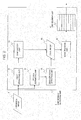
- Fig. 1 is a block diagram illustrating the first exemplary embodiment of the present invention
- Fig. 2 is a block diagram illustrating the line segment detection unit of the present invention.
- An original image 1 is normally configured of images of three components of R (red), G (green), and B (blue), and an image conversion unit 2 converts the original image I into an luminance image 3 and a color difference image 4.
- RGB that is obtained from the original image 1 is converted into three components of Y constituting the luminance image 3, C b and C r each constituting the color difference image 4.
- the luminance image 3 that is configured of a Y component is sharpened; however, a conversion from RGB to CIELAB color space is made, and a brightness image that is configured of its L* component may be regarded as the luminance image 3 and be sharpened: Further, with regard to the luminance component and the brightness component, not only the above-mentioned YC b C r and color space CIELA but also the color space such as YUV and HSV may be utilized. Further, with the case that the original image is a single-color image, only the luminance image is sharpened because no color difference component exists.
- a line segment detection unit 5 extracts the edges within the luminance image 3.
- a specific example of the line segment detection unit 5 will be explained by making a reference Fig. 2 .
- a first derivative unit 51 and a second derivative unit 52 act on the luminance image 3.
- a zero-crossing detection unit 53 is caused to act on an output of the second derivative unit 52.
- a binarization unit 54 is caused to act on an output of the first derivative unit 51.
- the output of the zero-crossing detection unit 53 is a one-pixel wide edge image; however much nose is simultaneously detected therefrom.
- the output of the binarization unit 54 is an edge region with a wide width. Combining these two makes it possible to obtain a one-pixel wide edge image 55 having less noise.
- " Computer Image Processing" written by Tamura Hideyuki, pp. 182-197, 2002, Ohmsha, Ltd . can be referenced.
- An edge tracking unit 56 tracks the edge detected in the edge image 55, and files the part to which a straight line can be applied as a line segment into a line segment list 57.
- An example, of the content of the line segment list 57 is shown in Fig. 3 .
- Fig. 3 shows an example of the line segment list 57 into which four line segments have been written.
- a third-place line segment is a five-pixel long line segment that is comprised of five pixels of (2, 4), (2, 5), (2, 6), (2, 7), and (2, 8).
- Fig. 4 is a view for showing these detected four line segments as a pixel unit. Additionally, herein, it is assumed that the left and top coordinate is (0, 0).
- a sharpening strength map creation unit 6 creates a sharpening strength map image 7. Firstly, the sharpening strength map creation unit 6 writes a sharpening strength ⁇ 0 that is applied to an entirety of the image into each pixel of the sharpening strength map image 7. Secondly, the sharpening strength map creation unit 6 investigates a length of each line segment created in the line segment list 57 of the line segment detection unit 5, and to begin with, with regard to the line segments of which a length l is equal to or more than a threshold 1 th , writes a sharpening strength ⁇ 1 for giving a strong sharpness into 1 n pixels existing near the above line segments of the sharpening strength map image 7.
- the sharpening strength map creation unit 6 forms the sharpening strength map image 7 such that the edges near the edge line segments of which the length 1 is equal to or more than the threshold 1 th are emphasized more strongly. And, finally, with regard to the line segments created in the line segment list 57 of the line segment detection unit 5 of which the length 1 is less than the threshold 1 th , the sharpening strength map creation unit 6 writes a weak sharpening strength ⁇ 2 into 1 n pixels near the above line segments of the sharpening strength map image 7 likewise. Herein, when ⁇ 1 has been already written into the pixel, the sharpening strength map creation unit 6 overwrites the weak sharpening strength ⁇ 2 into a position of the above pixel.
- the above-mentioned threshold 1 th and 1 n are constant, respectively, that with an depend upon the conditions under which the above images are observed, and are decided with an experiment. For example, with the case of printing the image at 12 pixels/mm, a value of 20 to 30 pixels is appropriate as the threshold 1 th , and at this moment, a good result is often obtained when 1 n is set to 10 pixels or so; however, this is not always true. That is, it is desirable to decide the optimum threshold by making the experiment because these thresholds are only yardsticks.
- the above-mentioned process aims for applying the sharpening to the linear edge part. That is, the similar process is desirably applied to not only the strictly straight line but also the curve having an arc.
- the line segments have been linked, the line segments are regarded as one line segment by employing the above linkability, or the threshold 1 th is decided in such a manner that the length of the above divided line segments satisfies the condition of the threshold 1 th .
- width 1 n of the adjacency in which the sharpening is performer, and the sharpening strength ⁇ 1 are given as constants, it is also possible to enhance these constants, for example, by adaptively changing them with a linear function or a non-linear function associated with the length of the related line segment.
- selecting parameters based upon the length of the shorter edge makes it possible to suppress deficiency such as the sharpness of the image being too high when a plurality of the edges exist adjacently.
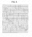
- the pixels forming the line segments are hatched and shown, ⁇ 2 is written into the pixels existing within the distance 1 n from the line segment with a line segment number 1, of which the length is less than 1 th , ⁇ 1 is written into the pixels that exist within the distance In from the line segments with a line segment number 2, a line segment number 3, and a line segment number 4 and yet do not exist within the distance 1 n from the line segment with a line segment number 1, and the strength of ⁇ 0 is written into the residual pixels.
- An image sharpening unit 8 performs the sharpening for each pixel of the luminance image 3 by making a reference to the sharpening strength map image 7, for example, in such a manner of Equation (4).
- Y ⁇ i j Y i j + ⁇ i j ⁇ Y i j - ⁇ k , l ⁇ Y ⁇ i - k , j - l ⁇ g k l
- Y (i,j) is a pixel value in a position (i, j) of the luminance image 3
- Y' (i, j) is a pixel value in a position (i, j) of a sharpened luminance image 9 that is obtained as a result of performing the sharpness process.
- g (k, 1) is a Kernel function of convolution for the luminance image Y, and a Gaussian function or the like is employed for it.
- the sharpened luminance image 9 to which the sharpening suitable for each part of the image has been applied is obtained.
- the sharpening by the unsharp masking of the Equation (1) is adopted in this example, the other sharpening such as a DOG (Difference of Gaussian) filter that is conventionally employed as an term within ⁇ ⁇ can be also utilized.
- DOG Difference of Gaussian
- An image conversion unit 10 creates sharpened images 11 expressed for each pixel with R, G, and B from the sharpened luminance image 9 subjected to the sharpness process and the color difference image 4 according to Equation (5).
- ⁇ R ⁇ Y ⁇ + 1.4020 ⁇ C r
- G ⁇ Y ⁇ - 0.3441 ⁇ C b - 0.7141 ⁇ C r
- B ⁇ Y ⁇ + 1.7720 ⁇ C b
- Fig. 6 is a view illustrating a configuration of the image processing device, being a second example of the present invention.
- a line segment detection unit 15 is configured to separately handle three components of R, G, and B of the original image 1, is configured to include the above-described line segment detection units 5 threefold, or is configured so that the line segment detection unit 5 sequentially handles three components.
- the sharpening strength map image 7 is obtained by the sharpening strength map creation unit 6 similarly to the first exemplary embodiment.
- An image sharpening unit 18 performs the sharpening for each of the three components of R, G, and B of the original image 1, whereby the Equation (5) behaves like Equation (6).
- ⁇ R ⁇ i j R i j + ⁇ i j ⁇ R i j - ⁇ k , l ⁇ R ⁇ i - k , j - l ⁇ g k l
- G ⁇ i j G i j + ⁇ i j ⁇ G i j - k , l ⁇ G ⁇ i - k , j - l ⁇ g k l
- B ⁇ i j B i j + ⁇ i j ⁇ B i j - ⁇ k , l ⁇ B ⁇ i - k , j - l ⁇ g k l
- Supplementary note 3 An image processing method according to Supplementary note 1 or Supplementary note 2, comprising:
- Supplementary note 4 An image processing method according to one of Supplementary note 1 to Supplementary note 3, comprising applying, when said image is an RGB image, said sharpening process for each image of respective components of said RGB.
- Supplementary note 5 An image processing method according to one of Supplementary note 1 to Supplementary note 4, comprising deciding the strength of the sharpening process based upon a length of the short edge when a plurality of the edges exist adjacently.
- Supplementary note 6 An image processing method according to one of Supplementary note 1 to Supplementary note 5, comprising deciding an application scope of the sharpening process based upon a length of the short edge when a plurality of the edges exist adjacently.
- An image processing device comprising:
- An image processing device comprising an image creation unit that creates a luminance image and a color difference image or a chromaticity image from the image; wherein said image sharpening strength decision unit decides the strength of the sharpening process based upon said luminance image; and wherein said sharpening processing unit comprises an image conversion unit that:
- Supplementary note 10 An image processing device according to one of Supplementary note 7 to Supplementary note 9, wherein when the image is an RGB image, the image sharpening strength decision unit and the sharpening processing unit are mounted for each image of respective components of said RGB.
- Supplementary note 15 A program according to Supplementary note 13 or Supplementary note 14, causing the information processing device to execute an image creation process of creating a luminance image and a color difference image or a chromaticity image from the image; wherein said image sharpening strength decision process decides the strength of the sharpening process based upon said luminance image; and wherein said sharpening process executes a process of:
- Supplementary note 16 A program according to one of Supplementary note 13 to Supplementary note 15, said program executing, when the image is an RGB image, the image sharpening strength decision process and the sharpening process for each image of respective components of said RGB.
- Supplementary note 18 A program according to one of Supplementary note 13 to Supplementary note 17, wherein said image sharpening strength decision process decides an application scope of the sharpening process based upon a length of the short edge when a plurality of the edges exist adjacently.
- the present invention may be applied to applications for improving the image quality of the image by automatically correcting each part in the image so that it has the optimum sharpness when utilizing the images inputted from digital cameras or scanners for printing/displaying/website.
Landscapes
- Engineering & Computer Science (AREA)
- Multimedia (AREA)
- Signal Processing (AREA)
- Physics & Mathematics (AREA)
- General Physics & Mathematics (AREA)
- Theoretical Computer Science (AREA)
- Image Processing (AREA)
- Facsimile Image Signal Circuits (AREA)
- Color Image Communication Systems (AREA)
Abstract
Description
- The present invention relates to an image processing method, an image processing device, and a program therefor.
- In recent years, prevalence of computers and digital cameras has enabled anybody to photograph/print pictures with ease. For this reason, it is not rare for an individual to handle a large volume of images. In such a circumstance, the sufficient quality is not always obtained for the photographed images, depending upon photographing conditions at that moment. Thus, the technology of automatically image-correcting a large volume of the images responding to respective contents and improving the image quality thereof is required.
- The process of sharpening the images is often performer as one of the technologies of improving the image quality when the images photographed with digital camera, scanners or the like are displayed or printed. The technology that is called unsharp masking is widely employed as the sharpening technology (Non-patent literature 1). Upon assuming an image and an image obtained by blurring it to be f and fs, respectively, an image g sharpened like Equation (1) is obtained.

Where λ is a coefficient that is used at the moment of adding the part in which a space frequency of the image is high into an original image, namely, a coefficient for adjusting a strength of the sharpening, and the optimum value is employed for it as a result of making an trial for many images. For example, with the case of targeting artificial products such as buildings as scenes of the input images, a value that allows the strong sharpening to be added is preferably set for the coefficient for adjusting a strength of the sharpening, and on the other hand, a value that allows the weak sharpening to be added is preferably applied with the case of targeting natural products. - The method of adjusting parameters in the sharpening process according to image features in the images is also known.
Patent literature 1 states that a thickness of an edge (an edge emphasizing scope) has to be adjusted responding to the features of the images when the sharpness is emphasized for the digital images by executing the edge emphasis. And, as its adjusting method, the method is described of, when the edge exists near an objective pixel, adjusting the edge emphasis by changing an emphasis radius and a weight matrix with respect to a positional relation between the thickness of the above edge and the objective pixel. -
- PTL 1:
JP-P2001-53974A -
- NPL 1: Color Reproduction Theory written by J.A.C. Yule, Print society Publication Department, 1971.
- In the background arts, it is specified that the optimum value for the coefficient for adjusting a strength of the sharpening differs, depending upon the scene of the input signal, and it is described that for example, the strong sharpening is set when the artificial product is employed for the scene of the input signal, and the weak sharpening is set with the case of the natural product.
- However, the above situation is not always true. For example, out of the natural products like planets, the natural product like the artificial product, which is configured of beautiful straight lines and curves, also exists. For such images of the scenes, a process similar to the process that is performed for the artificial products is preferably processed in many cases. For this, it should be thought that it is not that the optimum process exit for the natural product and the artificial product, respectively, but that information for performing the optimum process for each part of the image exists.
- Further, as a method of emphasizing the sharpness for the part of the image, the method of paying an attention to a positional relation between the thickness of the edge and the objective pixel, and adjusting the edge strength responding to these features is described in the
Patent literature 1. - However, only the thickness and the position of the edge cannot cope with the optimum edge emphasis for the arbitrary input images sufficiently. For example, applying the emphasizing technique of the sharpness in accordance with the
Patent literature 1 to the images including such a region in which the short edges mass causes the sharpness to become excessive, and incurs a decline in the image quality. - Thereupon, the present invention has been accomplished in consideration of the above-mentioned problems, and an object thereof is to provide an image processing device, an image processing method, and an image processing program that improve the image quality of the image by optimizing the sharpness in the part of the image without relying upon attributes of subjects such as the natural product and the artificial product within the image.
- The present invention is an image processing method of detecting an edge from an image to which a sharpening process is to be applied, and based upon a length of said edge existing near a target pixel of the sharpening process, deciding a strength of the sharpening process in said target pixel.
- The present invention is an image processing device comprising: an image sharpening strength decision unit that detects an edge from an image to which a sharpening process is to be applied, and based upon a length of said edge existing near a target pixel of the sharpening process, decides a strength of the sharpening process in said target pixel; and a sharpening processing unit that performs sharpening of said image based upon said strength of the sharpening process.
- The present invention is a program for causing an information processing device to execute: an image sharpening strength decision process of detecting an edge from an image to which a sharpening process is to be applied, and based upon a length of said edge existing near a target pixel of the sharpening process, deciding a strength of the sharpening process in said target pixel; and a sharpening process of performing sharpening of said image based upon said strength decided by the image sharpening strength decision process.
- The present invention makes it possible to improve the image quality of the image by optimizing the sharpness in the part of the image without relying upon attributes of subjects such as the natural product and the artificial product within the image.
-
- [
Fig. 1] Fig. 1 is a block diagram illustrating a first exemplary embodiment of the present invention. - [
Fig. 2] Fig. 2 is a block diagram illustrating a line segment detection unit of the first exemplary embodiment. - [
Fig. 3] Fig. 3 is a view illustrating an example of contents that are filed into a line segment list. - [
Fig. 4] Fig. 4 is a view for explaining the first exemplary embodiment. - [
Fig. 5] Fig. 5 is a view for explaining the first exemplary embodiment. - [
Fig. 6] Fig. 6 is a block diagram illustrating a first exemplary embodiment of the present invention. - The exemplary embodiments of the present invention will be explained.
- The first exemplary embodiment will be explained. The first exemplary embodiment of the present invention will be explained by making a reference to
Fig. 1 andFig. 2 .Fig. 1 is a block diagram illustrating the first exemplary embodiment of the present invention,Fig. 2 is a block diagram illustrating the line segment detection unit of the present invention. - An
original image 1 is normally configured of images of three components of R (red), G (green), and B (blue), and animage conversion unit 2 converts the original image I into anluminance image 3 and acolor difference image 4. The sharpening process after it is applied to theluminance image 3. For example, according to Equation (2), RGB that is obtained from theoriginal image 1 is converted into three components of Y constituting theluminance image 3, Cb and Cr each constituting thecolor difference image 4. In this case, theluminance image 3 that is configured of a Y component is sharpened; however, a conversion from RGB to CIELAB color space is made, and a brightness image that is configured of its L* component may be regarded as theluminance image 3 and be sharpened: Further, with regard to the luminance component and the brightness component, not only the above-mentioned YCbCr and color space CIELA but also the color space such as YUV and HSV may be utilized. Further, with the case that the original image is a single-color image, only the luminance image is sharpened because no color difference component exists.
A linesegment detection unit 5 extracts the edges within theluminance image 3. A specific example of the linesegment detection unit 5 will be explained by making a referenceFig. 2 . A firstderivative unit 51 and a secondderivative unit 52 act on theluminance image 3. A zero-crossing detection unit 53 is caused to act on an output of the secondderivative unit 52. Further, abinarization unit 54 is caused to act on an output of the firstderivative unit 51. The output of the zero-crossing detection unit 53 is a one-pixel wide edge image; however much nose is simultaneously detected therefrom. The output of thebinarization unit 54 is an edge region with a wide width. Combining these two makes it possible to obtain a one-pixelwide edge image 55 having less noise. For these details, for example, "Computer Image Processing" written by Tamura Hideyuki, pp. 182-197, 2002, Ohmsha, Ltd. can be referenced. - As a method of extracting the edge from the image, many methods such as a Canny edge detection algorithm ("Digital Image Processing", 2004, pp. 209-210, Computer Graphic Arts Society (CG-ARTS Society) are conventionally known, so these can be also applied.
- An
edge tracking unit 56 tracks the edge detected in theedge image 55, and files the part to which a straight line can be applied as a line segment into aline segment list 57. An example, of the content of theline segment list 57 is shown inFig. 3 . -
Fig. 3 shows an example of theline segment list 57 into which four line segments have been written. For example, it shows that a third-place line segment is a five-pixel long line segment that is comprised of five pixels of (2, 4), (2, 5), (2, 6), (2, 7), and (2, 8). -
Fig. 4 is a view for showing these detected four line segments as a pixel unit. Additionally, herein, it is assumed that the left and top coordinate is (0, 0). - Straight line fitting can be executed by, for example, obtaining a straight line that allows a square sum of distances to be minimized with respect to n tracked pixels (xi, yi) (i=1, 2, ···, n), and assuming that the line segment has been fitted when the maximum value of the distance from the above straight line to each pixel is smaller than a pre-decided threshold.
- A sharpening strength
map creation unit 6 creates a sharpeningstrength map image 7. Firstly, the sharpening strengthmap creation unit 6 writes a sharpening strength λ0 that is applied to an entirety of the image into each pixel of the sharpeningstrength map image 7. Secondly, the sharpening strengthmap creation unit 6 investigates a length of each line segment created in theline segment list 57 of the linesegment detection unit 5, and to begin with, with regard to the line segments of which a length l is equal to or more than athreshold 1th, writes a sharpening strength λ1 for giving a strong sharpness into 1n pixels existing near the above line segments of the sharpeningstrength map image 7. That is, the sharpening strengthmap creation unit 6 forms the sharpeningstrength map image 7 such that the edges near the edge line segments of which thelength 1 is equal to or more than thethreshold 1th are emphasized more strongly. And, finally, with regard to the line segments created in theline segment list 57 of the linesegment detection unit 5 of which thelength 1 is less than thethreshold 1th, the sharpening strengthmap creation unit 6 writes a weak sharpening strength λ2 into 1n pixels near the above line segments of the sharpeningstrength map image 7 likewise. Herein, when λ1 has been already written into the pixel, the sharpening strengthmap creation unit 6 overwrites the weak sharpening strength λ2 into a position of the above pixel. - Additionally, the above-mentioned
threshold 1th and In Additionally, the above-mentionedthreshold threshold 1th, and at this moment, a good result is often obtained when 1n is set to 10 pixels or so; however, this is not always true. That is, it is desirable to decide the optimum threshold by making the experiment because these thresholds are only yardsticks. - Herein, the above-mentioned process aims for applying the sharpening to the linear edge part. That is, the similar process is desirably applied to not only the strictly straight line but also the curve having an arc. When, even though the curve having not the strictly straight line but the arc is divided into a plurality of the line segments with the above-mentioned process, the line segments have been linked, the line segments are regarded as one line segment by employing the above linkability, or the
threshold 1th is decided in such a manner that the length of the above divided line segments satisfies the condition of thethreshold 1th. While thewidth 1n of the adjacency in which the sharpening is performer, and the sharpening strength λ1 are given as constants, it is also possible to enhance these constants, for example, by adaptively changing them with a linear function or a non-linear function associated with the length of the related line segment. - Further, the sharpening strengths λ0, λ1, and λ2 are constants that depend upon the technique of the sharpening. In many cases, it does not matter that the sharpening strengths λ2 to be applied to the image region having short edge line segments that is often observed in the natural product or the like is placed equally to the sharpening strength λ o that is applied to an entirety of the image. In that case, one example of a relation of λ0, λ1, and λ2 behaves like Equation (3).

Additionally, a magnitude relation of λ0 and λ2 is not limited to the Equation (3), and it is enough that they are smaller thank λ1. - With regard to decision of parameters of the sharpening strength in the target pixel within the image and the width In of the adjacency, selecting parameters based upon the length of the shorter edge makes it possible to suppress deficiency such as the sharpness of the image being too high when a plurality of the edges exist adjacently.
-
Fig. 5 shows the sharpening strengths written into the sharpeningstrength map image 7 as a result of executing the above process for the line segment images ofFig. 4 with 1th = 4 and In = 2 set as an example, respectively. In the same figure, the pixels forming the line segments are hatched and shown, λ2 is written into the pixels existing within thedistance 1n from the line segment with aline segment number 1, of which the length is less than 1th, λ1 is written into the pixels that exist within the distance In from the line segments with aline segment number 2, aline segment number 3, and aline segment number 4 and yet do not exist within thedistance 1n from the line segment with aline segment number 1, and the strength of λ0 is written into the residual pixels. - An
image sharpening unit 8 performs the sharpening for each pixel of theluminance image 3 by making a reference to the sharpeningstrength map image 7, for example, in such a manner of Equation (4).
Where Y (i,j) is a pixel value in a position (i, j) of theluminance image 3, λ2(i,j) is a pixel value (= sharpening strength) in a position (i, j) of the sharpeningstrength map image 7, and Y' (i, j) is a pixel value in a position (i, j) of a sharpenedluminance image 9 that is obtained as a result of performing the sharpness process. g (k, 1) is a Kernel function of convolution for the luminance image Y, and a Gaussian function or the like is employed for it. An term within { } of the Equation (4), which becomes a component having a high space frequency of theluminance image 3, is equivalent to (f-fs) of the Equation (1): Adding this to the original luminance image Y allows the sharpening of theluminance image 3 to be performed. λ (i, j) is a parameter for controlling an extent of its addition in a pixel unit, and the strong sharpening is performed in the pixel position of λ2 (i; j) = λ1 and the weak sharpening, is performed in the pixel position of λ (i, j) = λ0 or λ (i, j) = λ2. - As a result of computation of the Equation (4), the sharpened
luminance image 9 to which the sharpening suitable for each part of the image has been applied is obtained. Additionally, while the sharpening by the unsharp masking of the Equation (1) is adopted in this example, the other sharpening such as a DOG (Difference of Gaussian) filter that is conventionally employed as an term within { } can be also utilized. - An
image conversion unit 10 creates sharpenedimages 11 expressed for each pixel with R, G, and B from the sharpenedluminance image 9 subjected to the sharpness process and thecolor difference image 4 according to Equation (5).
The configuration mentioned above allows a result of having applied the sharpening having an appropriate strength to theoriginal image 1 responding to the content of the image to be obtained in the sharpenedimage 11. - The second exemplary embodiment of the present invention will be explained.
-
Fig. 6 is a view illustrating a configuration of the image processing device, being a second example of the present invention. - While the original image was converted into the luminance image and the color difference image, and the sharpening was performed only for the luminance image in the first exemplary embodiment of the present invention, the image processing device, being the second exemplary embodiment, applies the sharpening to the RGB image because the almost same effect is obtained even though the sharpening is applied for each of the R component, the G component and the B component: Herein, a line
segment detection unit 15 is configured to separately handle three components of R, G, and B of theoriginal image 1, is configured to include the above-described linesegment detection units 5 threefold, or is configured so that the linesegment detection unit 5 sequentially handles three components. - After the line segments have been obtained in the
line segment list 57, the sharpeningstrength map image 7 is obtained by the sharpening strengthmap creation unit 6 similarly to the first exemplary embodiment. - An
image sharpening unit 18 performs the sharpening for each of the three components of R, G, and B of theoriginal image 1, whereby the Equation (5) behaves like Equation (6).
With the above-mentioned process, a sharpenedimage 21 is obtained. - Additionally, while it is also possible that the exemplary embodiments of the present invention described above are configured of hardware as apparent from the explanation described above, they can be also realized with a computer program .
- Additionally, while one part or an entirety of the above-mentioned exemplary embodiments can be described like the following supplementary notes, they are not limited to the following.
- Further, the content of the above-mentioned exemplary embodiments can be expressed as follows.
- (Supplementary note 1) An image processing method of detecting an edge from an image to which a sharpening process is to be applied, and based upon a length of said edge existing near a target pixel of the sharpening process, deciding a strength of the sharpening process in said target pixel.
- (Supplementary note 2) An image processing method according to
Supplementary note 1, comprising: - detecting the edge from the image;
- extracting an edge line segment, being a straight line, from said edge; and
- deciding the strength of the sharpening process in said target pixel based upon a length of the edge line segment existing near the target pixel of the sharpening process.
- (Supplementary note 3) An image processing method according to
Supplementary note 1 orSupplementary note 2, comprising: - creating a luminance image and a color difference image or a chromaticity image from the image;
- creating a sharpened luminance image by applying the sharpening process for said luminance image; and
- outputting a sharpened color image from said sharpened luminance image and said color difference image or said chromaticity image.
- (Supplementary note 4) An image processing method according to one of
Supplementary note 1 toSupplementary note 3, comprising applying, when said image is an RGB image, said sharpening process for each image of respective components of said RGB. - (Supplementary note 5) An image processing method according to one of
Supplementary note 1 toSupplementary note 4, comprising deciding the strength of the sharpening process based upon a length of the short edge when a plurality of the edges exist adjacently. - (Supplementary note 6) An image processing method according to one of
Supplementary note 1 toSupplementary note 5, comprising deciding an application scope of the sharpening process based upon a length of the short edge when a plurality of the edges exist adjacently. - (Supplementary note 7) An image processing device comprising:
- an image sharpening strength decision unit that detects an edge from an image to which a sharpening process is to be applied, and based upon a length of said edge existing near a target pixel of the sharpening process, decides a strength of the sharpening process in said target pixel; and
- a sharpening processing unit that performs sharpening of said image based upon said strength of the sharpening process.
- (Supplementary note 8) An image processing device according to
Supplementary note 7, wherein said image sharpening strength decision unit comprises: - an edge detection unit that detects the edge from the image;
- an edge line segment extraction unit that extracts an edge line segment, being a straight line, from said edge; and
- an edge strength decision unit that decides said strength of the sharpening process in said target pixel within the image based upon a length of said edge line segment existing adjacently.
- (Supplementary note 9) An image processing device according to
Supplementary note 7 orSupplementary note 8, comprising an image creation unit that creates a luminance image and a color difference image or a chromaticity image from the image;
wherein said image sharpening strength decision unit decides the strength of the sharpening process based upon said luminance image; and
wherein said sharpening processing unit comprises an image conversion unit that: - performs the sharpening process for said luminance image based upon said strength of the sharpening process, and creates a sharpened luminance image; and
- outputs a sharpened color image from said sharpened luminance image and said color difference image or said chromaticity image.
- (Supplementary note 10) An image processing device according to one of
Supplementary note 7 toSupplementary note 9, wherein when the image is an RGB image, the image sharpening strength decision unit and the sharpening processing unit are mounted for each image of respective components of said RGB. - (Supplementary note 11) An image processing device according to one of
Supplementary note 7 toSupplementary note 10, wherein said image sharpening strength decision unit decides the strength of the sharpening process based upon a length of the short edge when a plurality of the edges exist adjacently. - (Supplementary note 12) An image processing device according to one of
Supplementary note 7 toSupplementary note 11, wherein said image sharpening strength decision unit decides an application scope of the sharpening process based upon a length of the short edge when a plurality of the edges exist adjacently. - (Supplementary note 13) A program for causing an information processing device to execute:
- an image sharpening strength decision process of detecting an edge from an image to which a sharpening process is to be applied, and based upon a length of said edge existing near a target pixel of the sharpening process, deciding a strength of the sharpening process in said target pixel; and
- a sharpening process of performing sharpening of said image based upon said strength decided by the image sharpening strength decision process.
- (Supplementary note 14) A program according to
Supplementary note 13, wherein said image sharpening strength decision process comprises: - an edge detection process of detecting the edge from the image;
- an edge line segment extraction process of extracting an edge line segment, being a straight line, from said edge; and
- an edge strength decision process of deciding said strength of the sharpening process in said target pixel within the image based upon a length of said edge line segment existing adjacently.
- (Supplementary note 15) A program according to
Supplementary note 13 orSupplementary note 14, causing the information processing device to execute an image creation process of creating a luminance image and a color difference image or a chromaticity image from the image;
wherein said image sharpening strength decision process decides the strength of the sharpening process based upon said luminance image; and
wherein said sharpening process executes a process of: - performing the sharpening process for said luminance image based upon said strength of the sharpening process, and creating a sharpened luminance image; and
- outputting a sharpened color image from said sharpened luminance image and said color difference image or said chromaticity image.
- (Supplementary note 16) A program according to one of
Supplementary note 13 toSupplementary note 15, said program executing, when the image is an RGB image, the image sharpening strength decision process and the sharpening process for each image of respective components of said RGB. - (Supplementary note 17) A program according to one of
Supplementary note 13 to Supplementary note 16, wherein said image sharpening strength decision process decides the strength of the sharpening process based upon a length of the short edge when a plurality of the edges exist adjacently. - (Supplementary note 18) A program according to one of
Supplementary note 13 to Supplementary note 17, wherein said image sharpening strength decision process decides an application scope of the sharpening process based upon a length of the short edge when a plurality of the edges exist adjacently. - Above, although the present invention has been particularly described with reference to the preferred embodiments, it should be readily apparent to those of ordinary skill in the art that the present invention is not always limited to the above-mentioned embodiment, and changes and modifications in the form and details may be made without departing from the spirit and scope of the invention.
- This application is based upon and claims the benefit of priority from Japanese patent application No.
2009-190248, filed on August 19, 2009 - The present invention may be applied to applications for improving the image quality of the image by automatically correcting each part in the image so that it has the optimum sharpness when utilizing the images inputted from digital cameras or scanners for printing/displaying/website.
-
- 1
- original image
- 2
- image conversion unit
- 3
- luminance image
- 4
- color difference image
- 5
- line segment detection unit
- 6
- sharpening strength map creation unit
- 7
- sharpening strength map image
- 8
- image sharpening unit
- 9
- sharpened luminance image
- 10
- image conversion unit
- 11
- sharpened image
- 15
- line segment detection unit
- 18
- image sharpening unit
- 21
- sharpened image
- 51
- first derivative unit
- 52
- second derivative unit
- 53
- zero-crossing detection unit
- 54
- binarization unit
- 55
- edge image
- 56
- edge tracking unit
- 57
- line segment list
Claims (18)
- An image processing method of detecting an edge from an image to which a sharpening process is to be applied, and based upon a length of said edge existing near a target pixel of the sharpening process, deciding a strength of the sharpening process in said target pixel.
- An image processing method according to claim 1, comprising:detecting the edge from the image;extracting an edge line segment, being a straight line, from said edge; anddeciding the strength of the sharpening process in said target pixel based upon a length of the edge line segment existing near the target pixel of the sharpening process.
- An image processing method according to claim 1 or claim 2, comprising:creating a luminance image and a color difference image or a chromaticity image from the image;creating a sharpened luminance image by applying the sharpening process for said luminance image; andoutputting a sharpened color image from said sharpened luminance image and said color difference image or said chromaticity image.
- An image processing method according to one of claim 1 to claim 3, comprising applying, when said image is an RGB image, said sharpening process for each image of respective components of said RGB.
- An image processing method according to one of claim 1 to claim 4, comprising deciding the strength of the sharpening process based upon a length of the short edge when a plurality of the edges exist adjacently.
- An image processing method according to one of claim 1 to claim 5, comprising deciding an application scope of the sharpening process based upon a length of the short edge when a plurality of the edges exist adjacently.
- An image processing device comprising:an image sharpening strength decision unit that detects an edge from an image to which a sharpening process is to be applied, and based upon a length of said edge existing near a target pixel of the sharpening process, decides a strength of the sharpening process in said target pixel; anda sharpening processing unit that performs sharpening of said image based upon said strength of the sharpening process.
- An image processing device according to claim 7, wherein said image sharpening strength decision unit comprises:an edge detection unit that detects the edge from the image;an edge line segment extraction unit that extracts an edge line segment, being a straight line, from said edge; andan edge strength decision unit that decides said strength of the sharpening process in said target pixel within the image based upon a length of said edge line segment existing adjacently.
- An image processing device according to claim 7 or claim 8, comprising an image creation unit that creates a luminance image and a color difference image or a chromaticity image from the image;
wherein said image sharpening strength decision unit decides the strength of the sharpening process based upon said luminance image; and
wherein said sharpening processing unit comprises an image conversion unit that:performs the sharpening process for said luminance image based upon said strength of the sharpening process, and creates a sharpened luminance image; andoutputs a sharpened color image from said sharpened luminance image and said color difference image or said chromaticity image. - An image processing device according to one of claim 7 to claim 9, wherein when the image is an RGB image, the image sharpening strength decision unit and the sharpening processing unit are mounted for each image of respective components of said RGB.
- An image processing device according to one of claim 7 to claim 10, wherein said image sharpening strength decision unit decides the strength of the sharpening process based upon a length of the short edge when a plurality of the edges exist adjacently.
- An image processing device according to one of claim 7 to claim 11, wherein said image sharpening strength decision unit decides an application scope of the sharpening process based upon a length of the short edge when a plurality of the edges exist adjacently.
- A program for causing an information processing device to execute:an image sharpening strength decision process of detecting an edge from an image to which a sharpening process is to be applied, and based upon a length of said edge existing near a target pixel of the sharpening process, deciding a strength of the sharpening process in said target pixel; anda sharpening process of performing sharpening of said image based upon said strength decided by the image sharpening strength decision process.
- A program according to claim 13, wherein said image sharpening strength decision process comprises:an edge detection process of detecting the edge from the image;an edge line segment extraction process of extracting an edge line segment, being a straight line, from said edge; andan edge strength decision process of deciding said strength of the sharpening process in said target pixel within the image based upon a length of said edge line segment existing adjacently.
- A program according to claim 13 or claim 14, causing the information processing device to execute an image creation process of creating a luminance image and a color difference image or a chromaticity image from the image;
wherein said image sharpening strength decision process decides the strength of the sharpening process based upon said luminance image; and
wherein said sharpening process executes a process of:performing the sharpening process for said luminance image based upon said strength of the sharpening process, and creating a sharpened luminance image; andoutputting a sharpened color image from said sharpened luminance image and said color difference image or said chromaticity image. - A program according to one of claim 13 to claim 15, said program executing, when the image is an RGB image, the image sharpening strength decision process and the sharpening process for each image of respective components of said RGB.
- A program according to one of claim 13 to claim 16, wherein said image sharpening strength decision process decides the strength of the sharpening process based upon a length of the short edge when a plurality of the edges exist adjacently.
- A program according to one of claim 13 to claim 17, wherein said image sharpening strength decision process decides an application scope of the sharpening process based upon a length of the short edge when a plurality of the edges exist adjacently.
Applications Claiming Priority (2)
| Application Number | Priority Date | Filing Date | Title |
|---|---|---|---|
| JP2009190248 | 2009-08-19 | ||
| PCT/JP2010/063391 WO2011021518A1 (en) | 2009-08-19 | 2010-08-06 | Image processing method, image processing device, and program |
Publications (3)
| Publication Number | Publication Date |
|---|---|
| EP2469834A1 true EP2469834A1 (en) | 2012-06-27 |
| EP2469834A4 EP2469834A4 (en) | 2014-01-22 |
| EP2469834B1 EP2469834B1 (en) | 2021-04-21 |
Family
ID=43606973
Family Applications (1)
| Application Number | Title | Priority Date | Filing Date |
|---|---|---|---|
| EP10809863.3A Active EP2469834B1 (en) | 2009-08-19 | 2010-08-06 | Image processing method, image processing device, and program |
Country Status (6)
| Country | Link |
|---|---|
| US (1) | US9083913B2 (en) |
| EP (1) | EP2469834B1 (en) |
| JP (1) | JP5614550B2 (en) |
| KR (1) | KR20120042988A (en) |
| CN (1) | CN102484673B (en) |
| WO (1) | WO2011021518A1 (en) |
Families Citing this family (5)
| Publication number | Priority date | Publication date | Assignee | Title |
|---|---|---|---|---|
| KR102056664B1 (en) * | 2012-10-04 | 2019-12-17 | 한국전자통신연구원 | Method for work using the sensor and system for performing thereof |
| US9264579B2 (en) * | 2014-03-26 | 2016-02-16 | Fuji Xerox Co., Ltd. | Correction control device, image reading apparatus, and correction control method |
| KR102087681B1 (en) | 2015-09-17 | 2020-03-11 | 삼성전자주식회사 | Image processing device, method for processing image and computer-readable recording medium |
| JP6763637B2 (en) * | 2016-08-19 | 2020-09-30 | 正浩 小林 | Image restoration method |
| CN111028182B (en) * | 2019-12-24 | 2024-04-26 | 北京金山云网络技术有限公司 | Image sharpening method, device, electronic device and computer-readable storage medium |
Family Cites Families (24)
| Publication number | Priority date | Publication date | Assignee | Title |
|---|---|---|---|---|
| BE558594A (en) * | 1953-09-03 | |||
| JPH09135331A (en) | 1995-11-10 | 1997-05-20 | Ricoh Co Ltd | Image processing device |
| US5901253A (en) * | 1996-04-04 | 1999-05-04 | Hewlett-Packard Company | Image processing system with image cropping and skew correction |
| JP3568732B2 (en) | 1997-04-18 | 2004-09-22 | シャープ株式会社 | Image processing device |
| JPH11284854A (en) | 1998-03-26 | 1999-10-15 | Ricoh Co Ltd | Image processing device |
| JP2000155841A (en) * | 1998-11-19 | 2000-06-06 | Nippon Telegr & Teleph Corp <Ntt> | Graphic recognition method, device therefor and recording medium recorded with graphic recognition program |
| JP3736219B2 (en) | 1999-08-13 | 2006-01-18 | コニカミノルタビジネステクノロジーズ株式会社 | Image processing apparatus and method |
| JP2001186353A (en) | 1999-12-27 | 2001-07-06 | Noritsu Koki Co Ltd | Image processing method and recording medium recording image processing program |
| AU1342502A (en) | 2000-09-20 | 2002-04-02 | Nik Multimedia Inc | Digital image sharpening system |
| JP4269521B2 (en) | 2001-01-24 | 2009-05-27 | コニカミノルタビジネステクノロジーズ株式会社 | Image processing apparatus and image forming apparatus |
| JP2003101774A (en) * | 2001-09-25 | 2003-04-04 | Ricoh Co Ltd | Image processing device |
| JP2004172704A (en) * | 2002-11-18 | 2004-06-17 | Kyocera Mita Corp | Image forming apparatus |
| US7269296B2 (en) | 2003-01-16 | 2007-09-11 | Samsung Electronics Co., Ltd. | Method and apparatus for shoot suppression in image detail enhancement |
| US7079687B2 (en) | 2003-03-06 | 2006-07-18 | Seiko Epson Corporation | Method and apparatus for segmentation of compound documents |
| JP2005141477A (en) | 2003-11-06 | 2005-06-02 | Noritsu Koki Co Ltd | Image sharpening processing method and image processing apparatus for implementing the method |
| JP4333544B2 (en) | 2004-02-13 | 2009-09-16 | セイコーエプソン株式会社 | Image processing method, image processing apparatus, semiconductor device, electronic device, image processing program, and computer-readable recording medium |
| KR100648308B1 (en) * | 2004-08-12 | 2006-11-23 | 삼성전자주식회사 | Resolution conversion method and device |
| KR100688757B1 (en) | 2005-01-07 | 2007-03-02 | 삼성전기주식회사 | Edge emphasis device and method of image data |
| JP4182990B2 (en) * | 2006-06-02 | 2008-11-19 | セイコーエプソン株式会社 | Printing device, method for determining whether image is blurred, and computer program |
| US8249357B2 (en) * | 2006-10-23 | 2012-08-21 | Ben Gurion University Of The Negev, Research And Development Authority | Blind restoration of images degraded by isotropic blur |
| CN100478993C (en) * | 2007-07-13 | 2009-04-15 | 天津大学 | Image reinforcement method for self-adaptive regulation according to edge and brightness |
| CN101345825B (en) * | 2008-01-24 | 2010-06-02 | 华硕电脑股份有限公司 | How to Adjust Blurred Images |
| US20090196524A1 (en) * | 2008-02-05 | 2009-08-06 | Dts Digital Images, Inc. | System and method for sharpening of digital images |
| JP4706723B2 (en) * | 2008-06-06 | 2011-06-22 | 朝日航洋株式会社 | Method and apparatus for reducing and compiling figures |
-
2010
- 2010-08-06 EP EP10809863.3A patent/EP2469834B1/en active Active
- 2010-08-06 US US13/391,170 patent/US9083913B2/en active Active
- 2010-08-06 JP JP2011527636A patent/JP5614550B2/en not_active Expired - Fee Related
- 2010-08-06 KR KR1020127003990A patent/KR20120042988A/en not_active Ceased
- 2010-08-06 CN CN201080036836.7A patent/CN102484673B/en not_active Expired - Fee Related
- 2010-08-06 WO PCT/JP2010/063391 patent/WO2011021518A1/en not_active Ceased
Also Published As
| Publication number | Publication date |
|---|---|
| EP2469834A4 (en) | 2014-01-22 |
| CN102484673B (en) | 2015-12-16 |
| WO2011021518A1 (en) | 2011-02-24 |
| JPWO2011021518A1 (en) | 2013-01-24 |
| US20120155762A1 (en) | 2012-06-21 |
| US9083913B2 (en) | 2015-07-14 |
| EP2469834B1 (en) | 2021-04-21 |
| JP5614550B2 (en) | 2014-10-29 |
| KR20120042988A (en) | 2012-05-03 |
| CN102484673A (en) | 2012-05-30 |
Similar Documents
| Publication | Publication Date | Title |
|---|---|---|
| US6904169B2 (en) | Method and system for improving color images | |
| US7529425B2 (en) | Denoising method, apparatus, and program | |
| US9569827B2 (en) | Image processing apparatus and method, and program | |
| EP3200147B1 (en) | Image magnification method, image magnification apparatus and display device | |
| US7809208B2 (en) | Image sharpening with halo suppression | |
| US20110285871A1 (en) | Image processing apparatus, image processing method, and computer-readable medium | |
| KR101812341B1 (en) | A method for edge enhancement of image | |
| CN109214996B (en) | Image processing method and device | |
| EP3407589B1 (en) | Image processing apparatus, image processing method, and storage medium | |
| EP2469834B1 (en) | Image processing method, image processing device, and program | |
| CN106485674A (en) | A kind of low light image Enhancement Method based on integration technology | |
| WO2011067755A1 (en) | Method and system for automatically recovering chromaticity and image variation of colour clipped image regions | |
| Hazlyna et al. | Comparison of acute leukemia Image segmentation using HSI and RGB color space | |
| WO2012153661A1 (en) | Image correction device, image correction display device, image correction method, program, and recording medium | |
| US9092862B2 (en) | Image processing apparatus, image adjusting apparatus, image processing method and computer readable medium | |
| JP5807555B2 (en) | Image processing program, apparatus and method | |
| JP7030425B2 (en) | Image processing device, image processing method, program | |
| US10979597B2 (en) | Image processing apparatus, image processing method, and program | |
| Tang et al. | Sky-preserved image dehazing and enhancement for outdoor scenes | |
| US8873862B2 (en) | Product image processor, product image processing method, information recording medium, and program | |
| Mittal et al. | An efficient video enhancement method using LA* B* analysis | |
| WO2014050689A1 (en) | Image processing device | |
| JP6928903B2 (en) | Image processing equipment, image processing methods, and programs | |
| US10475210B2 (en) | Image processing device, image processing method, and computer-readable recording medium | |
| JP2005039542A (en) | Image processor and method and program |
Legal Events
| Date | Code | Title | Description |
|---|---|---|---|
| PUAI | Public reference made under article 153(3) epc to a published international application that has entered the european phase |
Free format text: ORIGINAL CODE: 0009012 |
|
| 17P | Request for examination filed |
Effective date: 20120214 |
|
| AK | Designated contracting states |
Kind code of ref document: A1 Designated state(s): AL AT BE BG CH CY CZ DE DK EE ES FI FR GB GR HR HU IE IS IT LI LT LU LV MC MK MT NL NO PL PT RO SE SI SK SM TR |
|
| DAX | Request for extension of the european patent (deleted) | ||
| A4 | Supplementary search report drawn up and despatched |
Effective date: 20140103 |
|
| RIC1 | Information provided on ipc code assigned before grant |
Ipc: H04N 1/46 20060101ALI20131218BHEP Ipc: G06T 5/20 20060101ALI20131218BHEP Ipc: H04N 1/60 20060101ALI20131218BHEP Ipc: G06T 3/00 20060101ALI20131218BHEP Ipc: H04N 1/409 20060101AFI20131218BHEP |
|
| STAA | Information on the status of an ep patent application or granted ep patent |
Free format text: STATUS: EXAMINATION IS IN PROGRESS |
|
| 17Q | First examination report despatched |
Effective date: 20171222 |
|
| REG | Reference to a national code |
Ref country code: DE Ref legal event code: R079 Ref document number: 602010066846 Country of ref document: DE Free format text: PREVIOUS MAIN CLASS: H04N0001409000 Ipc: G06T0005000000 |
|
| GRAP | Despatch of communication of intention to grant a patent |
Free format text: ORIGINAL CODE: EPIDOSNIGR1 |
|
| STAA | Information on the status of an ep patent application or granted ep patent |
Free format text: STATUS: GRANT OF PATENT IS INTENDED |
|
| RIC1 | Information provided on ipc code assigned before grant |
Ipc: H04N 1/409 20060101ALI20201123BHEP Ipc: G06T 5/00 20060101AFI20201123BHEP |
|
| INTG | Intention to grant announced |
Effective date: 20201216 |
|
| RIN1 | Information on inventor provided before grant (corrected) |
Inventor name: TSUKADA, MASATO Inventor name: TAJIMA, JOHJI |
|
| GRAS | Grant fee paid |
Free format text: ORIGINAL CODE: EPIDOSNIGR3 |
|
| GRAA | (expected) grant |
Free format text: ORIGINAL CODE: 0009210 |
|
| STAA | Information on the status of an ep patent application or granted ep patent |
Free format text: STATUS: THE PATENT HAS BEEN GRANTED |
|
| AK | Designated contracting states |
Kind code of ref document: B1 Designated state(s): AL AT BE BG CH CY CZ DE DK EE ES FI FR GB GR HR HU IE IS IT LI LT LU LV MC MK MT NL NO PL PT RO SE SI SK SM TR |
|
| REG | Reference to a national code |
Ref country code: GB Ref legal event code: FG4D |
|
| REG | Reference to a national code |
Ref country code: CH Ref legal event code: EP |
|
| REG | Reference to a national code |
Ref country code: DE Ref legal event code: R096 Ref document number: 602010066846 Country of ref document: DE |
|
| REG | Reference to a national code |
Ref country code: IE Ref legal event code: FG4D |
|
| REG | Reference to a national code |
Ref country code: AT Ref legal event code: REF Ref document number: 1385433 Country of ref document: AT Kind code of ref document: T Effective date: 20210515 |
|
| REG | Reference to a national code |
Ref country code: LT Ref legal event code: MG9D |
|
| REG | Reference to a national code |
Ref country code: AT Ref legal event code: MK05 Ref document number: 1385433 Country of ref document: AT Kind code of ref document: T Effective date: 20210421 |
|
| REG | Reference to a national code |
Ref country code: NL Ref legal event code: MP Effective date: 20210421 |
|
| PG25 | Lapsed in a contracting state [announced via postgrant information from national office to epo] |
Ref country code: LT Free format text: LAPSE BECAUSE OF FAILURE TO SUBMIT A TRANSLATION OF THE DESCRIPTION OR TO PAY THE FEE WITHIN THE PRESCRIBED TIME-LIMIT Effective date: 20210421 Ref country code: NL Free format text: LAPSE BECAUSE OF FAILURE TO SUBMIT A TRANSLATION OF THE DESCRIPTION OR TO PAY THE FEE WITHIN THE PRESCRIBED TIME-LIMIT Effective date: 20210421 Ref country code: FI Free format text: LAPSE BECAUSE OF FAILURE TO SUBMIT A TRANSLATION OF THE DESCRIPTION OR TO PAY THE FEE WITHIN THE PRESCRIBED TIME-LIMIT Effective date: 20210421 Ref country code: AT Free format text: LAPSE BECAUSE OF FAILURE TO SUBMIT A TRANSLATION OF THE DESCRIPTION OR TO PAY THE FEE WITHIN THE PRESCRIBED TIME-LIMIT Effective date: 20210421 Ref country code: BG Free format text: LAPSE BECAUSE OF FAILURE TO SUBMIT A TRANSLATION OF THE DESCRIPTION OR TO PAY THE FEE WITHIN THE PRESCRIBED TIME-LIMIT Effective date: 20210721 Ref country code: HR Free format text: LAPSE BECAUSE OF FAILURE TO SUBMIT A TRANSLATION OF THE DESCRIPTION OR TO PAY THE FEE WITHIN THE PRESCRIBED TIME-LIMIT Effective date: 20210421 |
|
| PG25 | Lapsed in a contracting state [announced via postgrant information from national office to epo] |
Ref country code: LV Free format text: LAPSE BECAUSE OF FAILURE TO SUBMIT A TRANSLATION OF THE DESCRIPTION OR TO PAY THE FEE WITHIN THE PRESCRIBED TIME-LIMIT Effective date: 20210421 Ref country code: IS Free format text: LAPSE BECAUSE OF FAILURE TO SUBMIT A TRANSLATION OF THE DESCRIPTION OR TO PAY THE FEE WITHIN THE PRESCRIBED TIME-LIMIT Effective date: 20210821 Ref country code: GR Free format text: LAPSE BECAUSE OF FAILURE TO SUBMIT A TRANSLATION OF THE DESCRIPTION OR TO PAY THE FEE WITHIN THE PRESCRIBED TIME-LIMIT Effective date: 20210722 Ref country code: SE Free format text: LAPSE BECAUSE OF FAILURE TO SUBMIT A TRANSLATION OF THE DESCRIPTION OR TO PAY THE FEE WITHIN THE PRESCRIBED TIME-LIMIT Effective date: 20210421 Ref country code: PT Free format text: LAPSE BECAUSE OF FAILURE TO SUBMIT A TRANSLATION OF THE DESCRIPTION OR TO PAY THE FEE WITHIN THE PRESCRIBED TIME-LIMIT Effective date: 20210823 Ref country code: NO Free format text: LAPSE BECAUSE OF FAILURE TO SUBMIT A TRANSLATION OF THE DESCRIPTION OR TO PAY THE FEE WITHIN THE PRESCRIBED TIME-LIMIT Effective date: 20210721 Ref country code: PL Free format text: LAPSE BECAUSE OF FAILURE TO SUBMIT A TRANSLATION OF THE DESCRIPTION OR TO PAY THE FEE WITHIN THE PRESCRIBED TIME-LIMIT Effective date: 20210421 Ref country code: ES Free format text: LAPSE BECAUSE OF FAILURE TO SUBMIT A TRANSLATION OF THE DESCRIPTION OR TO PAY THE FEE WITHIN THE PRESCRIBED TIME-LIMIT Effective date: 20210421 |
|
| REG | Reference to a national code |
Ref country code: DE Ref legal event code: R097 Ref document number: 602010066846 Country of ref document: DE |
|
| PG25 | Lapsed in a contracting state [announced via postgrant information from national office to epo] |
Ref country code: RO Free format text: LAPSE BECAUSE OF FAILURE TO SUBMIT A TRANSLATION OF THE DESCRIPTION OR TO PAY THE FEE WITHIN THE PRESCRIBED TIME-LIMIT Effective date: 20210421 Ref country code: EE Free format text: LAPSE BECAUSE OF FAILURE TO SUBMIT A TRANSLATION OF THE DESCRIPTION OR TO PAY THE FEE WITHIN THE PRESCRIBED TIME-LIMIT Effective date: 20210421 Ref country code: CZ Free format text: LAPSE BECAUSE OF FAILURE TO SUBMIT A TRANSLATION OF THE DESCRIPTION OR TO PAY THE FEE WITHIN THE PRESCRIBED TIME-LIMIT Effective date: 20210421 Ref country code: DK Free format text: LAPSE BECAUSE OF FAILURE TO SUBMIT A TRANSLATION OF THE DESCRIPTION OR TO PAY THE FEE WITHIN THE PRESCRIBED TIME-LIMIT Effective date: 20210421 Ref country code: SM Free format text: LAPSE BECAUSE OF FAILURE TO SUBMIT A TRANSLATION OF THE DESCRIPTION OR TO PAY THE FEE WITHIN THE PRESCRIBED TIME-LIMIT Effective date: 20210421 Ref country code: SK Free format text: LAPSE BECAUSE OF FAILURE TO SUBMIT A TRANSLATION OF THE DESCRIPTION OR TO PAY THE FEE WITHIN THE PRESCRIBED TIME-LIMIT Effective date: 20210421 |
|
| PLBE | No opposition filed within time limit |
Free format text: ORIGINAL CODE: 0009261 |
|
| STAA | Information on the status of an ep patent application or granted ep patent |
Free format text: STATUS: NO OPPOSITION FILED WITHIN TIME LIMIT |
|
| 26N | No opposition filed |
Effective date: 20220124 |
|
| REG | Reference to a national code |
Ref country code: CH Ref legal event code: PL |
|
| PG25 | Lapsed in a contracting state [announced via postgrant information from national office to epo] |
Ref country code: MC Free format text: LAPSE BECAUSE OF FAILURE TO SUBMIT A TRANSLATION OF THE DESCRIPTION OR TO PAY THE FEE WITHIN THE PRESCRIBED TIME-LIMIT Effective date: 20210421 |
|
| REG | Reference to a national code |
Ref country code: BE Ref legal event code: MM Effective date: 20210831 |
|
| GBPC | Gb: european patent ceased through non-payment of renewal fee |
Effective date: 20210806 |
|
| PG25 | Lapsed in a contracting state [announced via postgrant information from national office to epo] |
Ref country code: LI Free format text: LAPSE BECAUSE OF NON-PAYMENT OF DUE FEES Effective date: 20210831 Ref country code: CH Free format text: LAPSE BECAUSE OF NON-PAYMENT OF DUE FEES Effective date: 20210831 |
|
| PG25 | Lapsed in a contracting state [announced via postgrant information from national office to epo] |
Ref country code: IS Free format text: LAPSE BECAUSE OF FAILURE TO SUBMIT A TRANSLATION OF THE DESCRIPTION OR TO PAY THE FEE WITHIN THE PRESCRIBED TIME-LIMIT Effective date: 20210821 Ref country code: LU Free format text: LAPSE BECAUSE OF NON-PAYMENT OF DUE FEES Effective date: 20210806 Ref country code: AL Free format text: LAPSE BECAUSE OF FAILURE TO SUBMIT A TRANSLATION OF THE DESCRIPTION OR TO PAY THE FEE WITHIN THE PRESCRIBED TIME-LIMIT Effective date: 20210421 |
|
| PG25 | Lapsed in a contracting state [announced via postgrant information from national office to epo] |
Ref country code: IT Free format text: LAPSE BECAUSE OF FAILURE TO SUBMIT A TRANSLATION OF THE DESCRIPTION OR TO PAY THE FEE WITHIN THE PRESCRIBED TIME-LIMIT Effective date: 20210421 Ref country code: IE Free format text: LAPSE BECAUSE OF NON-PAYMENT OF DUE FEES Effective date: 20210806 Ref country code: GB Free format text: LAPSE BECAUSE OF NON-PAYMENT OF DUE FEES Effective date: 20210806 Ref country code: FR Free format text: LAPSE BECAUSE OF NON-PAYMENT OF DUE FEES Effective date: 20210831 Ref country code: BE Free format text: LAPSE BECAUSE OF NON-PAYMENT OF DUE FEES Effective date: 20210831 |
|
| PGFP | Annual fee paid to national office [announced via postgrant information from national office to epo] |
Ref country code: DE Payment date: 20220819 Year of fee payment: 13 |
|
| PG25 | Lapsed in a contracting state [announced via postgrant information from national office to epo] |
Ref country code: HU Free format text: LAPSE BECAUSE OF FAILURE TO SUBMIT A TRANSLATION OF THE DESCRIPTION OR TO PAY THE FEE WITHIN THE PRESCRIBED TIME-LIMIT; INVALID AB INITIO Effective date: 20100806 Ref country code: CY Free format text: LAPSE BECAUSE OF FAILURE TO SUBMIT A TRANSLATION OF THE DESCRIPTION OR TO PAY THE FEE WITHIN THE PRESCRIBED TIME-LIMIT Effective date: 20210421 |
|
| REG | Reference to a national code |
Ref country code: DE Ref legal event code: R119 Ref document number: 602010066846 Country of ref document: DE |
|
| PG25 | Lapsed in a contracting state [announced via postgrant information from national office to epo] |
Ref country code: MK Free format text: LAPSE BECAUSE OF FAILURE TO SUBMIT A TRANSLATION OF THE DESCRIPTION OR TO PAY THE FEE WITHIN THE PRESCRIBED TIME-LIMIT Effective date: 20210421 |
|
| PG25 | Lapsed in a contracting state [announced via postgrant information from national office to epo] |
Ref country code: DE Free format text: LAPSE BECAUSE OF NON-PAYMENT OF DUE FEES Effective date: 20240301 |
|
| PG25 | Lapsed in a contracting state [announced via postgrant information from national office to epo] |
Ref country code: MT Free format text: LAPSE BECAUSE OF FAILURE TO SUBMIT A TRANSLATION OF THE DESCRIPTION OR TO PAY THE FEE WITHIN THE PRESCRIBED TIME-LIMIT Effective date: 20210421 |
|
| PG25 | Lapsed in a contracting state [announced via postgrant information from national office to epo] |
Ref country code: TR Free format text: LAPSE BECAUSE OF FAILURE TO SUBMIT A TRANSLATION OF THE DESCRIPTION OR TO PAY THE FEE WITHIN THE PRESCRIBED TIME-LIMIT Effective date: 20210421 |