EP2469658A2 - Connector - Google Patents
Connector Download PDFInfo
- Publication number
- EP2469658A2 EP2469658A2 EP11179187A EP11179187A EP2469658A2 EP 2469658 A2 EP2469658 A2 EP 2469658A2 EP 11179187 A EP11179187 A EP 11179187A EP 11179187 A EP11179187 A EP 11179187A EP 2469658 A2 EP2469658 A2 EP 2469658A2
- Authority
- EP
- European Patent Office
- Prior art keywords
- connecting terminals
- insulating members
- terminal housing
- insulating
- insulating member
- Prior art date
- Legal status (The legal status is an assumption and is not a legal conclusion. Google has not performed a legal analysis and makes no representation as to the accuracy of the status listed.)
- Granted
Links
Images


Classifications
-
- H—ELECTRICITY
- H01—ELECTRIC ELEMENTS
- H01R—ELECTRICALLY-CONDUCTIVE CONNECTIONS; STRUCTURAL ASSOCIATIONS OF A PLURALITY OF MUTUALLY-INSULATED ELECTRICAL CONNECTING ELEMENTS; COUPLING DEVICES; CURRENT COLLECTORS
- H01R13/00—Details of coupling devices of the kinds covered by groups H01R12/70 or H01R24/00 - H01R33/00
- H01R13/02—Contact members
- H01R13/26—Pin or blade contacts for sliding co-operation on one side only
-
- B—PERFORMING OPERATIONS; TRANSPORTING
- B60—VEHICLES IN GENERAL
- B60L—PROPULSION OF ELECTRICALLY-PROPELLED VEHICLES; SUPPLYING ELECTRIC POWER FOR AUXILIARY EQUIPMENT OF ELECTRICALLY-PROPELLED VEHICLES; ELECTRODYNAMIC BRAKE SYSTEMS FOR VEHICLES IN GENERAL; MAGNETIC SUSPENSION OR LEVITATION FOR VEHICLES; MONITORING OPERATING VARIABLES OF ELECTRICALLY-PROPELLED VEHICLES; ELECTRIC SAFETY DEVICES FOR ELECTRICALLY-PROPELLED VEHICLES
- B60L50/00—Electric propulsion with power supplied within the vehicle
- B60L50/50—Electric propulsion with power supplied within the vehicle using propulsion power supplied by batteries or fuel cells
- B60L50/51—Electric propulsion with power supplied within the vehicle using propulsion power supplied by batteries or fuel cells characterised by AC-motors
-
- H—ELECTRICITY
- H01—ELECTRIC ELEMENTS
- H01R—ELECTRICALLY-CONDUCTIVE CONNECTIONS; STRUCTURAL ASSOCIATIONS OF A PLURALITY OF MUTUALLY-INSULATED ELECTRICAL CONNECTING ELEMENTS; COUPLING DEVICES; CURRENT COLLECTORS
- H01R13/00—Details of coupling devices of the kinds covered by groups H01R12/70 or H01R24/00 - H01R33/00
- H01R13/02—Contact members
- H01R13/193—Means for increasing contact pressure at the end of engagement of coupling part, e.g. zero insertion force or no friction
-
- H—ELECTRICITY
- H01—ELECTRIC ELEMENTS
- H01R—ELECTRICALLY-CONDUCTIVE CONNECTIONS; STRUCTURAL ASSOCIATIONS OF A PLURALITY OF MUTUALLY-INSULATED ELECTRICAL CONNECTING ELEMENTS; COUPLING DEVICES; CURRENT COLLECTORS
- H01R13/00—Details of coupling devices of the kinds covered by groups H01R12/70 or H01R24/00 - H01R33/00
- H01R13/62—Means for facilitating engagement or disengagement of coupling parts or for holding them in engagement
- H01R13/639—Additional means for holding or locking coupling parts together, after engagement, e.g. separate keylock, retainer strap
-
- H—ELECTRICITY
- H01—ELECTRIC ELEMENTS
- H01R—ELECTRICALLY-CONDUCTIVE CONNECTIONS; STRUCTURAL ASSOCIATIONS OF A PLURALITY OF MUTUALLY-INSULATED ELECTRICAL CONNECTING ELEMENTS; COUPLING DEVICES; CURRENT COLLECTORS
- H01R24/00—Two-part coupling devices, or either of their cooperating parts, characterised by their overall structure
- H01R24/60—Contacts spaced along planar side wall transverse to longitudinal axis of engagement
- H01R24/62—Sliding engagements with one side only, e.g. modular jack coupling devices
-
- B—PERFORMING OPERATIONS; TRANSPORTING
- B60—VEHICLES IN GENERAL
- B60L—PROPULSION OF ELECTRICALLY-PROPELLED VEHICLES; SUPPLYING ELECTRIC POWER FOR AUXILIARY EQUIPMENT OF ELECTRICALLY-PROPELLED VEHICLES; ELECTRODYNAMIC BRAKE SYSTEMS FOR VEHICLES IN GENERAL; MAGNETIC SUSPENSION OR LEVITATION FOR VEHICLES; MONITORING OPERATING VARIABLES OF ELECTRICALLY-PROPELLED VEHICLES; ELECTRIC SAFETY DEVICES FOR ELECTRICALLY-PROPELLED VEHICLES
- B60L2240/00—Control parameters of input or output; Target parameters
- B60L2240/10—Vehicle control parameters
- B60L2240/36—Temperature of vehicle components or parts
-
- H—ELECTRICITY
- H01—ELECTRIC ELEMENTS
- H01R—ELECTRICALLY-CONDUCTIVE CONNECTIONS; STRUCTURAL ASSOCIATIONS OF A PLURALITY OF MUTUALLY-INSULATED ELECTRICAL CONNECTING ELEMENTS; COUPLING DEVICES; CURRENT COLLECTORS
- H01R2107/00—Four or more poles
-
- H—ELECTRICITY
- H01—ELECTRIC ELEMENTS
- H01R—ELECTRICALLY-CONDUCTIVE CONNECTIONS; STRUCTURAL ASSOCIATIONS OF A PLURALITY OF MUTUALLY-INSULATED ELECTRICAL CONNECTING ELEMENTS; COUPLING DEVICES; CURRENT COLLECTORS
- H01R2201/00—Connectors or connections adapted for particular applications
- H01R2201/26—Connectors or connections adapted for particular applications for vehicles
-
- Y—GENERAL TAGGING OF NEW TECHNOLOGICAL DEVELOPMENTS; GENERAL TAGGING OF CROSS-SECTIONAL TECHNOLOGIES SPANNING OVER SEVERAL SECTIONS OF THE IPC; TECHNICAL SUBJECTS COVERED BY FORMER USPC CROSS-REFERENCE ART COLLECTIONS [XRACs] AND DIGESTS
- Y02—TECHNOLOGIES OR APPLICATIONS FOR MITIGATION OR ADAPTATION AGAINST CLIMATE CHANGE
- Y02T—CLIMATE CHANGE MITIGATION TECHNOLOGIES RELATED TO TRANSPORTATION
- Y02T10/00—Road transport of goods or passengers
- Y02T10/60—Other road transportation technologies with climate change mitigation effect
- Y02T10/70—Energy storage systems for electromobility, e.g. batteries
Definitions
- the invention relates to a connector used for, e.g., an ceo-friendly car such as a hybrid car and an electric car and, in particular, to a connector that may be used for a power harness for transmitting a large amount of power.
- a power harness is used for connecting between devices such as between a motor and an inverter or between an inverter and a battery in, e.g., a hybrid car or an electric car, which has made significant progress in recent years, for transmitting a large amount of power, and a connector in a two-divided structure composed of, e.g., a male connector portion provided with a male terminal as well as a first terminal housing for housing the male terminal and a female connector portion provided with a female terminal connected to the male terminal as well as a second terminal housing for housing the female terminal is provided to one end of the power harness (see, e.g., JP-A-2009-070754 ).
- Japanese patent No. 4037199 discloses a downsizing technique.
- Japanese patent No. 4037199 discloses an electric connection structure for vehicle in which connecting terminals of plural phases of conductive member led out from a vehicle driving motor are connected to connecting terminals of plural phases of power line cable led out from an inverter for driving the motor, a connecting terminal of each phase of the conductive member overlaps a corresponding connecting terminal of each phase of the power line cable, an insulating member is arranged on a surface opposite to an overlapping surface of the connecting terminals, and the overlapped connecting terminals of each phase are tightened and fixed to the insulating members in an overlapping direction by a single bolt provided at a position to penetrate therethrough.
- Japanese patent No. 4037199 discloses the connection structure that the plural connecting terminals and the insulating members compose a laminated structure and the connecting terminals are fixed and electrically connected all together at contact points by tightening the single bolt in the overlapping direction (or the lamination direction) while the plural contact points between the connecting terminals as the overlapping surface thereof are sandwiched.
- the connection structure may be more effective than the technique of JP-A-2009-070754 in facilitating the downsizing.
- the inventors are convinced that the connector equipped with the laminated-type connection structure as in Japanese patent No. 4037199 needs further to be downsized.
- the insulating members are each fixed to one side of connecting terminals at the tip portion so as to omit the retaining jig.
- the measure also has the following problem.
- a connector is provided with an insulating member assembly assembled such that insulating members (which compose the insulating member assembly) are restricted from moving in a fitting direction and a width direction thereof (i.e., these directions being perpendicular to each other) by connecting the insulating members as engaged to each other, Accordingly, it is possible to prevent the position of the insulating members from being misaligned even when a force (e.g., a force to pull or push a cable connected with the connector) is applied to the cable. As a result, when two connector portions of the connector are fitted to each other, second connecting terminals (to be inserted between the insulating members) can be prevented from butting to the insulating members so as to smooth the lifting operation.
- the connector can be downsized since the embodiment of the invention can omit the retaining jig unlike the conventional connector by using the insulating member assembly thus assembled.
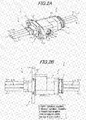
- FIGS.1A , 1B , 2A and 2B are diagrams illustrating a connector in an embodiment, wherein FlG.1A is a cross sectional view, FIG.1B is a side view showing first connecting terminals and an insulating member assembly, FIG.2A is a perspective view and FIG.2B is a plan view.
- a connector 1 of the present, embodiment is composed of a first connector portion 2 and a second connector portion 3 , and plural power lines are connected at a time by fitting the connector portions 2 and 3 together.
- the connector 1 is provided with the first connector potion 2 having a first terminal housing (i.e., male terminal housing) 5 housing plural (three) aligned first connecting terminals (i.e., male terminals) 4 a to 4 c, the second connector portion 3 having a second terminal housing (i.e., female terminal housing) 7 housing plural (three) aligned second connecting terminals (i.e., female terminals) 6 a to 6 c, and plural (four) insulating members 8 a to 8 d aligned and housed in the first terminal housing 5 for insulating the first connecting terminals 4 a to 4 c each other, and is configured that, in the first connector portion 2 and the second connector portion 3 which are fitted to each other, the first connecting terminals 4 a to 4 c, and the second connecting terminals 6 a to 6 c are alternately arranged to form laminated structure in which surface of the plural first connecting terminals 4 a to 4 c on one side face surfaces of the plural second connecting terminals 6 a to 6
- cables 60 a to 60 c are connected to the first connector portion 2 and cables 61 a to 61 c are connected to the second, connector portion 3 , and the cables 60 a to 60c are respectively electrically connected to the cables 61 a to 61 c by connecting the first connector portion 2 to the second connector portion 3 . That is, the connector 1 is used to connect cables.
- the connector 1 is used for connecting, e,g., a motor for driving a vehicle to an inverter for driving the motor.
- the cables 60 a to 60 c as cables extending from a motor and the cables 61 a to 61 c as cables extending from an inverter will be described as an example.
- the first connector portion 2 holds, inside thereof, three first connecting terminals 4 a to 4 c aligned at predetermined intervals, and is provided with the first terminal lousing 5 housing the three aligned first connecting terminals 4 a to 4 c, plural insulating members 8 a to 8 d in a substantially rectangular parallelepiped shape which are provided in the first terminal bousing 5 for insulating the first correcting terminals 4 a to 4 c from each other, and a connecting member 9 for collectively fixing and electrically connecting the plural first connecting terminals 4 a to 4 c to the plural second connecting terminals 6 a to 6 c at respective contact points by pressing the adjacent insulating member 8 a.
- the cables 60 a to 60 c extending from a motor are respectively connected to edges of the first connecting terminals 4 a to 4 c on one side.
- the cables 60 a to 60 c are each composed of a conductor 62 and an insulation layer 63 formed on the enter periphery thereof.
- the conductor 62 having a cross-sectional area of 20 mm 2 is used in the present embodiment.
- Electricity of different voltage and/or current is transmitted to each of the cables 60 a to 60 c,
- the present embodiment assumes the use of a three-phase AC power line between a motor and an inverter, and alternate current having a phase difference of 120 ° is transmitted to each of the cables 60 a to 60 c and the first connecting terminals 4 a to 4 c.
- Each of the first connecting terminals 4 a to 4 c should be formed of a highly conductive metal such as silver, copper or aluminum to reduce transmission loss, etc., in the connector 1 .
- each of the first connecting terminals 4 a to 4 c has little flexibility.
- the cables 60 a to 60 c are each aligned and held at predetermined intervals by a resin molded body (or inner housing) 10 which is in a multi-cylindrical shape (i.e., contiguous plural cylinders).
- the first connecting terminals 4 a to 4 c are fixed to the first terminal housing 5 via the cables 60 a to 60 c and the resin molded body 10 .
- the resin molded body 10 is formed of an insulating resin (e.g., PPS (polyphenylene sulfide) resin, PPA (polyphthalamide) resin, PA (polyamide) resin, PBT (polybutylene terephthalate) and epoxy-based resin), etc., to prevent short circuit by insulating the first connecting terminals 4 a to 4 c from each other.
- the resin molded body 10 allows the first connecting terminals 4 a to 4 c to be held at respective predetermined positions even when each of the cables 60 a to 60 c respectively connected to the first connecting terminals 4 a to 4 c is very flexible. In other words, since a cable excellent in flexibility can be used as the cables 60 a to 60 c in the present embodiment, it is possible to improve the wiring flexibility for laying the cables 60 a to 60 c.
- the resin molded body 10 holds the cables 60 a to 60 c to position the first connecting terminals 4 a to 4 c, in more detail, the resin molded body 10 holds the end portion of the cables 60 a to 60 c at a position close to the first connecting terminals 4 a to 4 c so that the first connecting terminals 4 a to 4 c are held at predetermined positions, however, the resin molded body 10 may directly hold and position the first connecting terminals 4 a to 4 c while holding the cables 60 a to 60 c. Alternatively, a connecting terminal holding member for directly holding the first connecting terminals 4 a to 4 c without holding the cables 60 a to 60 c may be used in place of the resin molded body 10 .
- the resin molded body 10 determines the positions of the first connecting terminals 4 a to 4 c by holding the cables 60 a to 60 c without directly holding the first connecting terminals 4 a to 4 c, i.e., in the case as is the present embodiment, use of flexible cables 60 a to 60 c allows the tips of the first connecting terminals 4 a to 4 c to flexibly move with respect to the first terminal housing 5 , and it is thereby possible to suppress deformation of the first connecting terminals 4 a to 4 c caused by pressure from the connecting member 9 .
- the first connector portion 2 is provided with a slip-off preventing mechanism 11 so that the cables 60 a to 60 c are not pulled out from the resin molded body 10 even when the cables 60 a to 60 c are pulled.
- the slip-off preventing mechanism 11 is composed of a protrusion 11 a each formed at the proximal ends of the first connecting terminals 4 a to 4 c (in the vicinity of the cables 60 a to 60 c) and a locking projection 11 b which is provided in each cylinder of the multi-cylindrical resin molded body 10 in a protruding manner to restrict backward movement (toward the left side in FIG.1A ) of the protrusion 11a by locking with the protrusion 11 a.
- each of the first connecting terminals 4 a to 4 c has a caulking portion 32 for caulking the conductor 62 which is exposed at end portions of the cables 60 a to 60 c and a plate-like contact point 33 integrally formed with the caulking portion 32 .
- the protrusions 11 a of the slip-off preventing mechanism 11 are formed to protrude upward (downward) from both widthwise end portions of the plate-like contact point 33 at the proximal end thereof.
- the present embodiment is configured such that the cables 60 a to 60 c are aligned and held with as little clearance as possible in order to downsize the connector 1. Therefore, a trunk portion 35 of the first connecting terminals 4 b connected to the cable 60 b which is arranged in the middle when aligned is bent so that the first connecting terminals 4 a to 4 c are arranged at equal intervals.
- the plural first insulating members 8 b to 8 d are aligned and housed in the first terminal housing 5 and are also provided integrally with the respective surfaces of the first connecting terminals 4 a to 4 c on another side (surfaces opposite to the surfaces connected to the second connecting terminals 6 a to 6 c), and a second insulating member 8 a is provided so as to face the surface of the outermost second connecting terminal 6a (the uppermost side in FIGS.1A and 1B ) on another side (a surface opposite to the surface connected to the first connecting terminal 4 a) when the plural first connecting terminals 4 a to 4 c and the plural second connecting terminals 6 a to 6c form a laminated state.
- the first insulating members 8 b to 8 d are provided on the first connecting terminals 4 a to 4 c at positions to protrude on the tip side.
- Each corner of the first insulating members 8 b to 8 d on a side to insert and extract the second connecting terminals 6 a to 6 c is chamfered.
- a corner of the second insulating member 8 a on a side to insert and extract the second connecting terminals 6 a to 6 c and also on the first insulating member 8 b side is also chamfered.
- a protruding portion (or a build-up surface) for filling level difference from the first connecting terminals 4 a to 4 c is each formed on the surfaces of the first insulating members 8 b to 8 d on which the first connecting terminals 4 a to 4 c are provided so that the upper surfaces (i.e., the upper side in the drawing) of the first insulating members 8 b to 8 d are respectively flush with the upper surfaces (i.e., the upper side in the drawing) of the first connecting terminals 4 a to 4 c.
- the tip portions of the first connecting terminals 4 a to 4 c do not contact with the tip portions of the second connecting terminals 6 a to 6 c to be inserted when the first connector portion 2 is fitted to the second connector portion 3 , hence, an effect of improving insertability of the second connecting terminals 6 a to 6 c.
- an insulating member assembly 100 is formed by connecting the insulating members 8 a to 8 d each other to restrict movement thereof in a fitting direction (i.e., a horizontal direction in FIGS.1A and 1B ) and movement of the laminated structure in a width direction (i.e., a depth direction or front-back direction in FIGS.1A and 1B ) which is perpendicular to a lamination direction (i.e., a vertical direction in FIGS.1A and 1B ) and to the fitting direction.
- a fitting direction i.e., a horizontal direction in FIGS.1A and 1B
- a width direction i.e., a depth direction or front-back direction in FIGS.1A and 1B
- lamination direction i.e., a vertical direction in FIGS.1A and 1B
- the connecting member 9 has a head portion 9 a in a substantially cylindrical shape, and the head portion 9 a is turned and moved toward the second insulating member 8 a by fitting a tool such as a wrench in an irregular shaped hole (i.e., a star-shaped hole in the embodiment) 9 b formed on the upper surface (i.e., a surface opposite to the second insulating member 8 a) of the head portion 9 a to press the second insulating member 8 a.
- a tool such as a wrench in an irregular shaped hole (i.e., a star-shaped hole in the embodiment) 9 b formed on the upper surface (i.e., a surface opposite to the second insulating member 8 a) of the head portion 9 a to press the second insulating member 8 a.
- a structure to turn and move the head portion 9 a toward the second insulating member 8a is not specifically limited here, and for example, it may be configured such that two protrusions are formed so as to protrude outward in a diameter direction from the opposite positions on the side surfaces of the head portion 9 a and are screwed together with a helical groove formed on the first terminal housing 5 .
- the connecting member 9 formed of e.g., a metal such as SUS, iron and a copper alloy should be used.
- the connecting member 9 formed of resin may be used, however, it is preferable to use the connecting member 9 formed of metal from the viewpoint of strength.
- a packing 14 for preventing water from entering into the first terminal housing 5 is provided on the outer periphery of the head portion 9 a.
- an elastic member 15 for imparting a predetermined pressing force to the second insulating member 8 a is provided between the lower surface of the head portion 9a of the connecting member 9 and the upper surface of the second insulating member 8 a immediately thereunder.
- a concave portion 9 c is formed on the lower surface of the head portion 9 a to house the upper portion of the elastic member 15 therein. This is an idea to reduce a distance between head portion 9 a and the second insulating member 8 a and to downsize the connector 1 even when the elastic member 15 is long to some extent.
- the elastic member 15 is composed of, e.g., a spring formed of metal (e.g., SUS, etc.).
- the elastic member 15 is regarded as a portion of the connecting member 9 in the present embodiment
- a concave portion 16 for covering (housing) a lower portion of the elastic member 15 is formed on the upper surface of the second insulating member 8a with which the lower portion of the elastic member 15 is in contact, and a receiving member 17 formed of metal (e.g., SUS, etc.) for preventing the second insulating member 8a formed of an insulating resin from being damaged by receiving the elastic member 15 is provided on a bottom of the concave portion 16 (i.e., a seat portion with which the lower portion of the elastic member 15 is in contact).
- metal e.g., SUS, etc.
- the receiving member 17 prevents damage of the second insulating member 8a by dispersing stress applied from the elastic member 15 to the upper surface of the second insulating member 8a . Therefore, a contact area between the receiving member 17 and the second insulating member 8a is preferably as large as possible.
- the receiving member 17 having a shape in contact throughout the entire bottom surface of the bottom of the concave portion 16 is provided in the present embodiment in order to increase the contact area between the receiving member 17 and the second insulating member 8a ,
- the first terminal housing 5 is formed of a hollow cylindrical body 20 having a substantially rectangular shaped horizontal cross-section.
- An outer peripheral portion of one side (on the right side in FIG.1A ) of the cylindrical body 20 which is fitted to the second terminal housing 7 is formed in a tapered shape in light of fitting properties to the second connector portion 3 .
- a terminal housing waterproof structure 21 for sealing between the first connector portion 2 and the second connector portion 3 is provided on the outer peripheral portion of the one side of the cylindrical body 20 .
- the terminal housing waterproof structure 21 is composed of a concave portion 22 formed on the outer peripheral portion of the one side of the cylindrical body 20 and a packing 23 such as an O-ring provided on the concave portion 22
- An assembly opening 20a which, opens on one side of the cylindrical shape is formed inside the cylindrical body 20 on another side (on the left side in FIG.1A ), i.e., opposite to the side to be fitted to the second terminal housing 7, and the insulating member assembly 100 and the resin molded body 10 arc inserted through the assembly opening 20a and then are fixed (details will be described later). At this time, only a portion of the resin molded body 10 on the tip side in an insertion direction is housed in the first terminal housing 5 and the remaining portion protrudes cut-ward from the first terminal housing 5 .
- a packing 10a for preventing water from entering into the first terminal housing 5 is provided on the outer periphery of the tip portion (a portion housed in the first terminal housing 5 ) of the resin molded body 10 .
- a non-illustrated non-packing airtight portion is formed on the resin molded body 10 on a cable insertion side to prevent water from trickling down through the cables 60a to 60c and entering into the first terminal housing 5 .
- a flange 24 for the first connector portion 2 to a vehicle body, etc.. is formed on the outer periphery of the other side of the cylindrical body 20 .
- the flange 24 has a mounting hole 24a through which a non-illustrated bolt is inserted for fixation to the vehicle body, etc.
- the flange 24 provided on the first connector portion 2 is described in the present embodiment, the flange 24 may be provided on the second connector portion 3 or on both the first connector portion 2 and the second connector portion 3 . Alternatively, the flange 24 may be omitted.
- the Sange 24 is effective to improve heat dissipation. That is, a surface area of the first terminal housing 5 can be increased by forming the flange 24, and it is thus possible to improve the heat dissipation when heat generated inside the first connector portion 2 (e.g., heat generated at each contact point) is released to the outside through the first terminal housing 5 .
- a connecting member insertion hole 26 for inserting the connecting member 9 therethrough is formed on the upper portion (on the upper side in FIG.1A ) of the cylindrical body 20 .
- a portion of the first terminal housing 5 as a periphery of the connecting member insertion hole 26 is formed in a cylindrical shape (a bellow cylindrical shape).
- the cylindrical body 20 is preferably formed of light metal having high electrical and thermal conductivity such as aluminum, but may be formed of resin, etc.
- the cylindrical body 20 is formed of aluminum.
- the second connector portion 3 will be described below.
- the second connector portion 3 has the second terminal housing 7 in which plural (three) aligned second connecting terminals (female terminals) 6a to 6c are housed,
- the cables 61a to 61c extending from the inverter side are respectively connected to edges of the second connecting terminals 6a to 6e on one side.
- the cables 61a to 61c are respectively electrically connected to the cables 60a to 60c via the first connecting terminals 4a to 4c and the second connecting terminals 6a to 6c , and electricity of different voltage and/or current corresponding to each of the cables 60a to 60c is transmitted.
- the cables 61a to 61c are the same cables as the cables 68a to 60c and are each composed of the conductor 62 and the insulation layer 63 formed on the outer periphery thereof, although the same cables as the cables 60a to 60c are used as the cables 61a to 61c , cables having different sizes may be used.
- the cables 61a to 61c are each aligned and held at predetermined intervals by a resin molded body (inner housing) 30 which is in a multi-cylindrical shape.
- the resin molded body 30 positions and holds the second connecting terminals 6a to 6c respectively on the first connecting terminals 4a to 4c (i.e., objects to be connected) which face the second connecting terminals 6a to 6c to be respectively paired therewith when the first connector portion 2 is fitted to the second connector portion 3 .
- the resin molded body 30 is formed of as insulating resin, etc., to prevent short circuit by insulating the second connecting terminals 6a to 6c from each other.
- the resin molded body 30 allows the second connecting terminals 6a to 6c to be held at respective predetermined positions even though each of the cables 61a to 61c respectively connected to the second connecting terminals 6a to 6c is very flexible.
- the resin molded body 30 positions the second connecting terminals 6a to 6c by holding the cables 61a to 61c , it is not limited thereto.
- the resin molded body 30 may directly hold and position the second connecting terminals 6a to 6c while holding the cables 61 a to 61 c.
- a connecting terminal holding member for directly holding the second connecting terminals 6 a to 6 c without holding the cables 61 a to 61 c may be used.
- the resin molded body 30 determines the positions of the second connecting terminals 6 a to 6 c by holding the cables 61 a to 61 c without directly holding the second connecting terminals 6 a to 6 c, i.e., is the case as is the present embodiment, use of flexible cables 61 a to 61 c allows the tips of the second connecting terminals 6 a to 6 c to flexibly move with respect to the second terminal housing 7 , and it is thereby possible to suppress deformation of the second connecting terminals 6 a to 6 c caused by pressure from the connecting member 9.
- a non-illustrated braided shield is wound around portions of the cables 61 a to 61 c which are pulled out from the second terminal housing 7 , in order to improve the shielding performance.
- the braided shield is in contact with a below-described cylindrical shield body 41 , and is electrically connected to the first terminal housing 5 via the cylindrical shield body 41 (the same potential (GND)).
- the second connector portion 3 is provided with a slip-off preventing mechanism 27 so that the cables 61 a to 61 c are not pulled out from the resin molded body 30 even when the cables 61 a to 61 c are pulled.
- the slip-off preventing mechanism 27 is composed of a protrusion 27 a each formed at the proximal ends of the second connecting terminals 6a to 6 c (in the vicinity of the cables 61 a to 61 c) and a locking projection 27 b which is provided in each cylinder of the multi-cylindrical resin molded body 30 in a protruding manner to restrict backward movement (toward the right side in FIG.1A ) of the protrusion 27 a by locking with the protrusion 27 a.
- each of the second connecting terminals 6 a to 6 c has a caulking portion 45 for caulking the conductor 62 which is exposed at a tip portion of the cables 61 a to 61 c and a plate-like contact point 46 integrally formed with the caulking portion 45 .
- a trunk portion 47 of the second connecting terminal 6 b connected to the cable 61 b which is arranged in the middle when aligned is bent so that the second connecting terminals 6 a to 6 c are arranged at equal intervals.
- the protrusion 27 a of the slip-off preventing mechanism 27 is formed to protrude upward (downward) from both widthwise end portions of the plate-like contact point 46 at the proximal end thereof.
- Each of the second connecting terminals 6 a to 6 c should be formed of a highly conductive metal such as silver, copper or aluminum to reduce transmission loss, etc., in the connector 1. In addition, each of the second connecting terminals 6 a to 6 c has little flexibility.
- the second terminal housing 7 is composed of a hollow cylindrical body 36 having a substantially rectangular horizontal cross section. Since the first terminal housing 5 is lifted in the second terminal housing 7 , an inner peripheral portion of the cylindrical body 36 on one side (on the left side in FIG.1A ) to be fitted to the first terminal housing 5 is formed in a tapered shape in light of fitting properties to the first, terminal housing 5 .
- the resin molded body 30 aligning and holding the cables 61 a to 61 c is housed in the cylindrical body 36 on the other end side (on the right side in FIG1A ).
- a non-packing airtight portion 43 is formed on the resin molded body 38 on a cable insertion side to prevent water from trickling down through the cables 61 a to 61 c and entering into the second terminal housing 7 .
- a packing 44 in contact with the resin molded body 30 is provided on the outer periphery of the non-packing airtight portion 43 .
- a packing 38 in contact with an inner peripheral surface of the first terminal housing 5 is provided on the outer peripheral portion of the resin molded body 30 . That is, the connector 1 has a double waterproof structure composed of the packing 23 of the terminal housing waterproof structure 21 and the packing 38 provided on the outer peripheral portion of the resin molded body 30 .
- the outer periphery of the cylindrical body 36 on the other end side from where the cables 61 a to 61 c are led out is covered by a rubber boot for preventing water from entering into the cylindrical body 36 , even though it is not illustrated.
- a connecting member manipulating hole 40 through which the connecting member 9 provided on the first connector portion 2 is manipulated when the second connector portion 3 is fitted to the first connector portion 2 , is formed on an upper portion of the cylindrical body 36 (on the upper side in FIG.1A ).
- the cylindrical body 36 is preferably formed of light metal having high electrical and thermal conductivity such as aluminum, but may be formed of resin, etc. Since the cylindrical body 36 is formed of an insulating resin in the present embodiment, the aluminum cylindrical shield body 41 is provided on an inner peripheral surface of the cylindrical body 36 on the other end side in order to improve the shielding performance and the heat dissipation.
- the cylindrical shield body 41 has a contact portion 42 which comes in contact with an outer periphery of the aluminum first terminal housing 5 when the first connector portion 2 is fitted to the second connector portion 3 , and the cylindrical shield body 41 and the first terminal housing 5 are thermally and electrically connected via the contact portion 42 .
- This improves the shielding performance and the heat dissipation.
- Significant improvement is expected particularly in the heat dissipation by actively releasing heat to the first terminal housing 5 which is excellent in heat dissipation.
- the second connecting terminals 6 a to 6 c are respectively inserted into gaps between the respective pairs of the first connecting terminals 4 a to 4 c and the insulating members 8 a to 8 d.
- the insertion provides a laminated structure in which the surfaces of the plural first connecting terminals 4 a to 4 c on one side face the surfaces of the plural second connecting terminals 6 a to 6 c on one side to form the respective pair, and the first connecting terminals 4 a to 4 c, the second connecting terminals 6 a to 6 c and the insulating members 8 a to 8 d are alternately arranged, i.e., the insulating members 8 a to 8 d are arranged so as to sandwich the pairs of the first connecting terminals 4 a to 4 c and the second connecting terminals 6 a to 6 c.
- each gap between the insulating members 8 b to 8 d can be kept without additionally providing a retaining jig for keeping gaps between the respective insulating members 8 b to 8 d (see Japanese patent No. 4037199 ).
- the insertion and extraction properties of the second connecting terminals 6 a to 6 c are not degraded.
- a contact point between the first connecting terminal 4 a and the second connecting terminal 6 a is sandwiched between the second insulating member 8 a and the first insulating member 8 b provided on the first connecting terminal 4 a constituting a contact point
- a contact point between the first connecting terminal 4 b (or 4 c) and the second connecting terminal 6 b (or 6 c) is sandwiched between the first insulating member 8 c (or 8 d) provided on the first connecting terminal 4 b (or 4 c) constituting a contact point and the first insulating member 8 b (or 8 c) provided on the first connecting terminal 4 a (or 4 b) constituting another contact point.
- the first connecting terminals 4 a to 4 c and the second connecting terminals 6 a to 6 c are bent in some degree due to pressure from the insulating members 8 a to 8 d and respectively make contact in a large area. This makes strong contact and fixation of each contact point even under the environment in which vibration occurs, such as in a vehicle.
- the insulating member assembly 100 as an essential portion of the invention will be described below.
- FIG.6 is a cross sectional view taken on line A-A in FIG.1B and FIG.7 is a cross sectional view taken on line B-B in FIG.3 , which is seen through a resin molded body.
- the insulating member assembly 100 is formed by sequentially connecting each of the insulating members 8 a to 8 d in the lamination direction. That is, the insulating member assembly 100 is formed by respectively connecting the second insulating member 8 a to the first insulating member 8 b , the first insulating member 8 b to the first insulating member 8 c , and the first insulating member 8 c to the first insulating member 8 d.
- the insulating member assembly 100 movement of the insulating members 8 a to 8 d in the fitting direction as well as in the width direction is restricted by connecting the insulating members 8 a to 8 d.
- the insulating members 8 a to 8 d are each connected to be relatively movable in the lamination direction in order to transmit a pressing force from the connecting member 9 to each contact point.
- a connecting part 81 extending from both widthwise end portions of the first insulating members 8 b to 8 d toward the opposite insulating members 8 a to 8 c (toward the second insulating member 8 a from the first insulating member 8 b, the first insulating member 8 b from the first insulating member 8 c and the first insulating member 8 c from the first insulating member 8 d) with the first connecting terminals 4 a to 4 c interposed therebetween on which the first insulating members 8b to 8d are provided is each integrally provided on the first insulating members 8 b to 8 d .
- a connecting groove 82 for receiving the connecting part 81 to be slidable in the lamination direction is each formed on the both side surfaces of the insulating members 8 a to 8 c opposite to the first insulating members 8 b to 8 d (facing with the first connecting terminals 4 a to 4 c interposed therebetween on which the first insulating members 8 b to 8 d are provided).
- the insulating members 8 a to 8 d are each connected to be relatively movable in the lamination direction by respectively receiving the connecting part 81 of the first insulating member 8 b in the connecting groove 82 of the second insulating member 8 a, the connecting part 81 of the first insulating member 8 c in the connecting groove 82 of the first insulating member 8 b and the connecting part 81 of the first insulating member 8 d in the connecting groove 82 of the first insulating member 8 c, and the insulating member assembly 100 is thereby formed.
- the connecting groove 82 is formed so that the width thereof in the fitting direction is substantially equal to that of the connecting part 81 to be received. This restricts the movement of the insulating members 8 a to 8 d in the fitting direction. Furthermore, the connecting parts 81 formed at the both widthwise end portions of the first insulating members 8 b to 8 d are received by the connecting grooves 82 formed on the both side surfaces of the opposite insulating members 8 a to 8 c, and thus, the opposite insulating members 8 a to 8 c are sandwiched by the connecting parts 81 in the width direction, which restricts the widthwise movement of the insulating members 8 a to 8 d.
- a tip (upper edge) of the connecting part 81 is restricted by a level difference 82 a as an end edge of the connecting groove 82 so that gaps between the insulating members 8 a to 8 d are not smaller than a predetermined gap (the minimum laminating gap).
- the minimum laminating gap is adjusted to be slightly smaller than each total thickness of the first connecting terminals 4 a to 4 c and the second connecting terminals 6 a to 6 c which compose contact points (contact point thickness). It is because, when the minimum laminating gap is larger than the contact point thickness, a pressing force from the connecting member 9 is not transmitted to the contact points, on the other hand, when the minimum laminating gap is too small, the insulating members 8 a to 8 d are largely misaligned in the lamination direction when the first connecting terminals 4 a to 4 c are deformed for some reasons and failure such as deterioration in fitting properties occurs.
- the minimum laminating gap can be adjusted by controlling a difference between a length of the connecting part 81 in the lamination direction and that of the connecting grove 82 (e.g., the minimum laminating gap is increased by making the connecting part 81 longer than the connecting groove 82 ).
- the insulating members 8a to 8d are formed so that the that the widths thereof are substantially equal to those of the first connecting terminals 4a to 4c .
- a widthwise gap of the connecting parts 81 formed at the both widthwise end portions of the first insulating members 8b to 8d (a gap between inner surfaces) is formed to be slightly smaller than the widths of the first connecting terminals 4a to 4c , and a squared U-shaped fitting groove 83 for fitting the widthwise end portions of the first connecting terminals 4a to 4c is formed at the proximal end of each connecting part 81 in order to provide the first insulating members 8b to 8d on the first connecting terminals 4a to 4c .
- the first insulating members 8b to 8d are provided on the first connecting terminals 4a to 4c by fitting the first connecting terminals 4a to 4c to the fitting grooves 83 .
- the first insulating members 8b to 8d are held by the first terminal housing 5 via the first connecting terminals 4a to 4c , the cables 60a to 60c and the resin molded body 10 , and the positions of the first insulating members 8b to 8d with respect to the first terminal housing 5 are thereby determined.
- a gap is formed between the tip of the connecting part 81 and the level difference 82a as an end edge of the connecting groove 82 in the state that the first insulating members 8b to 8d are positioned with respect to the first terminal housing 5 , and thus, the first insulating members 8b to 8d are respectively movable in the lamination direction.
- the width of the fitting groove 83 in the lamination direction (a width of a squared U-shaped opening) is formed to be slightly larger than the thickness of the first connecting terminals 4a to 4c .
- a gap (clearance) is formed between the fitting grooves 83 and the first connecting terminals 4a to 4c when the first connecting terminals 4a to 4c are fitted to the fitting grooves 83 and the first insulating members 8b to 8d are thus provided having looseness (or play) with respect to the first connecting terminals 4a to 4c .
- the first insulating members 8b to 8d are provided having looseness (or play) with respect to the first connecting terminals 4a to 4c , the first insulating members 8b to 8d are flexibly movable even when the positions thereof are slightly misaligned, and deterioration in fitting properties caused by the second connecting terminals 6a to 6c butting to the first insulating members 8b to 8d , etc., can be prevented, In addition, it is possible to easily fit the first connecting terminals 4a to 4c to the fitting grooves 83 by forming a gap (clearance) between the fitting grooves 83 and the first connecting terminals 4a to 4c .
- the connecting part 81 is formed to protrude outward in the width direction over the first insulating members 8b to 8d . This is to improve strength of the connecting part 81 by increasing the thickness thereof and to restrict widthwise movement of the insulating member assembly 100 by a contact of the outer surface of the connecting part 81 with the inner peripheral surface of the first terminal housing 5 (the cylindrical body 20 ). Therefore, a distance between the outer surfaces of the connecting part 81 formed at the both end portions of the first insulating members 8b to 8d is formed substantially equal to a gap between the inner peripheral surfaces of the first terminal housing 5 .
- engagement portions 84 and 85 for engaging the insulating member assembly 100 with the first terminal housing 5 are respectively formed at both end portions of the insulating member assembly 100 in the lamination direction, i.e., formed on the second insulating member 8a and the first insulating members 8d which are located outermost.
- the engagement portion 84 is formed to extend upward (opposite to the first insulating member 8b ) from the second insulating member 8a at a rear end portion in the fitting direction as well as at widthwise end portions, and to be bent at 90° above the second insulating member 8a so as to extend outward in the width direction.
- the engagement portion 84 is configured to be engaged with a partition wall 86 formed on the inner peripheral surface of the first terminal housing 5 and to determine the position of the insulating member assembly 100 in the fitting direction with respect to the first terminal housing 5 when the insulating member assembly 100 is inserted into the first terminal housing 5 (the cylindrical body 20 ) through the assembly opening 20a .
- the partition wall 86 is formed along the lamination direction on the inner peripheral surface of the first terminal housing 5 on both sides (right and left surfaces in FIG.7 ) at a position closer to the assembly opening 20a than to the connecting member insertion hole 26 .
- the engagement portion 84 moves along the partition wall 86 and the second insulating member 8a moves in the lamination direction.
- a level difference 86a is formed on the partition wall 86 so that the engagement portion 84 does not move beyond the level difference 86a (toward the first insulating member 8b side).
- the engagement portion 84 has a function of determining the position of the insulating member assembly 100 in the fitting direction, a function of guiding the movement of the second insulating member 8a in the lamination direction and a function of restricting the movement of the second insulating member 8a in the lamination direction to the lower limit (the position closest to the first insulating member 8b ).
- the engagement portion 85 is formed to extend downward (opposite to the first insulating member 8c ) from the first insulating member 8d at a rear end portion in the fitting direction as well as at widthwise end portions.
- the engagement portion 85 is configured to be engaged with a base 87 formed on the inner peripheral surface of the first terminal housing 5 and to determine, together with the engagement portion 84, the position of the insulating member assembly 100 in the fitting direction with respect to the first terminal housing 5 when the insulating member assembly 100 is inserted into the first terminal housing 5 (the cylindrical body 20) through the assembly opening 20a .
- the base 87 has both a function of engaging the engagement portion 85 and a function of restricting downward movement (opposite to the first insulating member 8c ) of the first insulating member 8d .
- the engagement portion 85 is formed to protrude outward in the width direction over the first insulating member 8d and a distance between the outer surfaces thereof in the width direction is the same as a distance between the outer surfaces of the connecting part 81 in the width direction (i.e., the same width as the connecting part 81 ). Furthermore, the engagement portion 85 is configured to extend upward along the rear end portion of the first insulating member 8d in the fitting direction so as to be connected to the lower portion of the connecting part 81 , and as a result, it is possible to increase an area in contact with the inner peripheral surface of the first terminal housing 5 (the cylindrical body 20 ) and to position the insulating member assembly 100 with respect to the first terminal housing 5 more stably.
- a surface of the upwardly extended portion of the engagement portion 85 on a front end side in the fitting direction is formed to be flush with an inner wall of the connecting groove 82 on a rear end side in the fitting direction, thereby serving to reinforce the connecting groove 82.
- the engagement portion 85 is formed not only on the first insulating member 8d but also on the first insulating members 8b and 8c .
- the engagement portion 85 is fundamentally unnecessary for the first insulating members 8 b and 8 c and can be omitted, forming the engagement portion 85 on the first insulating members 8 b and 8c allows the first insulating members 8 b to 8 d to have the same shape, thereby reducing the manufacturing cost.
- the first insulating member 8d has the connecting groove 82 which is fundamentally unnecessary for the same reason.
- the connecting part 81 is formed on the first insulating members 8 b to 8 d and the connecting groove 82 is formed on me opposite insulating members 8 a to 8 c, however, the relation between the connecting part 81 and the connecting groove 82 can be obviously reversed (the connecting part 81 is formed on the insulating members 8 a to 8 d and the connecting groove 82 is formed on the opposite insulating members 8 b to 8d in the insulating member assembly 100 ).
- the insulating member assembly 100 is inserted through the assembly opening 20a and is arranged in the first terminal housing 5 by respectively engaging the engagement portions 84 and 85 with the partition wall 86 and the base 87, and the resin molded body 10 is inserted through the assembly opening 20 a and is fixed to the first terminal housing 5.
- the engagement portions 84 and 85 are sandwiched between and held by the first terminal housing 5 (the partition wall 86 and the base 87 ) and the resin molded body 10, thereby fixing the insulating member assembly 100 to the first terminal housing 5.
- the insulating member assembly 100 is configured such that the movement of the insulating members 8 a to 8 d in the fitting direction as well as in the width direction is restricted by connecting the insulating members 8 a to 8 d.
- the connector 1 is small since a retaining jig is not used, unlike the conventional connector.
- the first insulating members 8 b to 8 d are provided having looseness with respect to the first connecting terminals 4 a to 4 c, the first insulating members 8 b to 8 d can he flexibly moved in accordance with the positions of the second connecting terminals 6 a to 6 c at the time of connecting the two connector portions 2 and 3 and it is thus possible to further improve the fitting properties.
- the connecting part 81 is formed to extend from the both widthwise end portions of the first insulating members 8 b to 8 d toward the opposite insulating members 8 a to 8 c with the first connecting terminals 4 a to 4 c interposed therebetween on which the first insulating members 8 b to 8 d are provided, and the connecting groove 82 receiving the connecting part 81 to be slidable in the lamination direction is formed on the both side surfaces of the opposite insulating members 8 a to 8c.
- each of the insulating members 8 a to 8 d relatively movable in the lamination direction, which allows the pressing force from the connecting member 9 to be transmitted to each contact point.
- the fitting groove 83 to which the widthwise end portions of the first connecting terminals 4 a to 4 c are fitted to provide the first insulating members 8 b to 8 d on the first connecting terminals 4 a to 4 c can be formed at the proximal end of the connecting part 81 , which allows the structure of the first insulating members 8 b to 8 d to be simplified.
- the connector 1 is configured such that the engagement portions 84 and 85 for engaging the insulating member assembly 100 with the first terminal housing 5 are formed at the both end portions of the insulating member assembly 100 in the lamination direction and the insulating member assembly 100 is fixed to the first terminal housing 5 by sandwiching and holding the engagement portions 84 and 85 between the first terminal housing 5 and the resin molded body 10.
- the present embodiment assumes the use of a three-phase AC power line, however, according to the technical idea of the invention, it may be, e.g., a connector for a vehicle which is configured to collectively connect lines used for different purposes such as a three-phase AC power line between a motor and an inverter and a two-phase DC power line for air conditioner Since the configuration described above allows one connector to collectively connect power lines used for different purposes, it is not necessary to prepare different connectors for each intended purpose and it is thus possible to contribute to space saving and cost reduction.
- terminal surfaces of the first connecting terminals 4 a to 4 c and the second connecting terminals 6 a to 6 c may be each roughened by a knurling process to increase frictional force so as to make the terminals difficult to move, thereby strengthening the fixation at each contact point.
- first connecting terminals 4 a to 4c provided at the end portions of the cables 60 a to 60 c have been described in the present embodiment, it is not limited thereto.
- the first connecting terminals 4 a to 4c may be a bus bar, etc., to which a cable is not connected.
- the first insulating members 8b to 8d may be fixed to the first connecting terminals 4 a to 4 c by insert molding or by press-fitting the first connecting terminals 4a to 4c into the first insulating members 8b to 3d.
- the first insulating members 8b to 8 d do not have looseness with respect to the first connecting terminals 4 a to 4c in the case of insert molding or press-fitting. Therefore, a structure in which the first connecting terminals 4 a to 4 c are fitted to the fitting groove 83 is desirable in light of improving the fitting properties,
- a rigid cable may be used.
- a direction of the connecting member 9 may be either substantially horizontal or substantially vertical when the connector is in use. In other words, a direction in a usage state is not a requirement in the use conditions of the connector of the present embodiment.
- the head portion 9 a of the connecting member 9 presses the second insulating member 8 a adjacent thereto via the elastic member 15 which is a portion of the connecting member 9 in the present embodiment
- the adjacent second insulating member 8 a may be pressed directly by the head portion 9 a, not via the elastic member 15 .
- the connecting member 9 may be provided on both sides of the first terminal housing 5 so that a pressing force is imparted to each contact point by the connecting members 9 provided on the both sides.
- connecting ember 9 is composed of only the head portion 9 a in the embodiment, a through type connecting member in which a shaft penetrating through each contact point is integrally formed with the head portion 9a may be used.
Landscapes
- Engineering & Computer Science (AREA)
- Life Sciences & Earth Sciences (AREA)
- Sustainable Development (AREA)
- Sustainable Energy (AREA)
- Power Engineering (AREA)
- Transportation (AREA)
- Mechanical Engineering (AREA)
- Connector Housings Or Holding Contact Members (AREA)
- Details Of Connecting Devices For Male And Female Coupling (AREA)
- Connections By Means Of Piercing Elements, Nuts, Or Screws (AREA)
- Coupling Device And Connection With Printed Circuit (AREA)
Abstract
Description
- The invention relates to a connector used for, e.g., an ceo-friendly car such as a hybrid car and an electric car and, in particular, to a connector that may be used for a power harness for transmitting a large amount of power.
- A power harness is used for connecting between devices such as between a motor and an inverter or between an inverter and a battery in, e.g., a hybrid car or an electric car, which has made significant progress in recent years, for transmitting a large amount of power, and a connector in a two-divided structure composed of, e.g., a male connector portion provided with a male terminal as well as a first terminal housing for housing the male terminal and a female connector portion provided with a female terminal connected to the male terminal as well as a second terminal housing for housing the female terminal is provided to one end of the power harness (see, e.g.,
JP-A-2009-070754 - In recent years, all components in such an eco-friendly car have been reduced in weight to improve the energy saving performance, and one effective measure for reducing the weight may be downsizing.
- For example, Japanese patent No.
4037199 - Japanese patent No.
4037199 - In other words, Japanese patent No.
4037199 JP-A-2009-070754 - However, the technique such as disclosed in Japanese patent No.
4037199 - (1) There is a problem that the number of parts increases since a retaining jig for holding one end of each insulating member is provided as a separate member.
- (2) Since the retaining jig for holding one end of each insulating member is a separate member, another problem arises that a connection portion between the retaining jig and the insulating member becomes large, so that the entire connection structure becomes large.
- Thus, the inventors are convinced that the connector equipped with the laminated-type connection structure as in Japanese patent No.
4037199 - However, the measure also has the following problem.
- (1) In case of the connecting terminal fixed to the cable, a problem arises that when an excessive force (e.g., a force to pull the cable or a force to push the cable into a connector) is applied to the cable, the connecting terminal may move and cause the misalignment of the insulating member. The similar problem occurs in a bus bar type connecting terminal (such as a male terminal 4 in
JP-A-2009-070754 - Accordingly, it is an object of the invention to provide a laminated structure type connector that can be downsized while preventing the misalignment of the insulating members.
- (1) According to one embodiment of the invention, a connector comprises:
- a first terminal housing for housing a plurality of first connecting terminals aligned;
- a second terminal housing for housing a plurality of second connecting terminals aligned;
- a plurality of insulating members that are aligned and housed in the first terminal housing;
- a laminated structure that the first connecting terminals and the second connecting terminals are alternately arranged so that one surface of the plurality of first connecting terminals faces one surface of the plurality of second connecting terminals to form pairs and to form a plurality of contact points sandwiched between the plurality of insulating members when the first terminal housing is fitted to the second terminal housing;
- a connecting member for collectively fixing and electrically connecting the plurality of first connecting terminals and the plurality of second connecting terminals at each contact point by pressing one of the plurality of insulating members adjacent to the connecting member; and
- an insulating member assembly comprising the plurality of insulating members assembled such that the plurality of insulating members are each restricted from moving in a fitting direction thereof, and moving in a width direction perpendicular to a lamination direction of the laminated structure and to the fitting direction.
- In the above embodiment (1) of the invention, the following modifications and changes can be made.
- (i) The plurality of insulating members comprise a plurality of first insulating members each provided on an other surface of the plurality of first connecting terminals, and a second, insulating member arranged to face an other surface of an outermost one of the plurality of second connecting terminals when the plurality of first connecting terminals and the plurality of second connecting terminals are laminated, and
the plurality of first insulating members are formed to have a looseness with the plurality of first connecting terminals. - (ii) One of the plurality of first insulating members comprises two connecting parts extending from both end portions thereof in a width direction thereof toward adjacent one of the plurality of first insulating members or the second insulating member to which the one of the plurality of first insulating members is opposite interposed by one of the plurality of first connecting terminals on which the one of the plurality of first insulating members is provided, and
the plurality of first insulating members or the second insulating member comprises connecting grooves for receiving the connecting parts to be slidable in the lamination direction on both opposite sides thereof. - (iii) The connecting parts comprise a fitting groove formed at a proximal end thereof for being fitted to an end portion of the plurality of first connecting terminals in a width direction thereof to provide the plurality of first insulating members on the plurality of first connecting terminals.
- (iv) The insulating member assembly comprises an engagement portion for being engaged with the first terminal housing at both ends thereof in the lamination direction.
- (v) The first terminal housing comprises an assembly opening on an opposite side to a side for being fitted to the second terminal housing, and
a resin molded body disposed such that after the insulating member assembly is inserted into and placed in the first terminal housing through the assembly opening, the resin molded body is inserted into and Sited to the first terminal housing through the assembly opening so as to sandwich the engagement portion between the first terminal housing and the resin molded body to fix the insulating member assembly to the first terminal housing. - (vi) The plurality of first connecting terminals comprise a terminal provided at an end portion of a cable,
the resin molded body is formed to hold the cable, and
the plurality of first connecting terminals are fixed to the first terminal housing via the cable and the resin molded body. - According to one embodiment of the invention, a connector is provided with an insulating member assembly assembled such that insulating members (which compose the insulating member assembly) are restricted from moving in a fitting direction and a width direction thereof (i.e., these directions being perpendicular to each other) by connecting the insulating members as engaged to each other, Accordingly, it is possible to prevent the position of the insulating members from being misaligned even when a force (e.g., a force to pull or push a cable connected with the connector) is applied to the cable. As a result, when two connector portions of the connector are fitted to each other, second connecting terminals (to be inserted between the insulating members) can be prevented from butting to the insulating members so as to smooth the lifting operation. Moreover, the connector can be downsized since the embodiment of the invention can omit the retaining jig unlike the conventional connector by using the insulating member assembly thus assembled.
- Next the present invention will be explained in more detail in conjunction with appended drawings, wherein:
-
FIGS.1A and 1B are diagrams illustrating a connector in an embodiment of the present invention, whereinFIG.1A is a cross sectional view andFIG.1B is a side view showing first connecting terminals and an insulating member assembly; -
FIG.2A is a perspective view showing the connector ofFIG.1 andFIG.2B is a plan view thereof; -
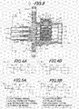
FIG.3 is a cross sectional view showing a first connector portion of the connector of FlG.1; - FlGS.4A and 4B are diagrams illustrating a second connecting terminal of the connector of
FIG.1 , wherein ofFIG.4A is a side view and ofFIG.4B is a top view; -
FIGS.5A and 5B are diagrams illustrating a second connecting terminal of the connector ofFIG.1 , wherein ofFIG.5A is a side view and ofFIG.5B is a top view; -
FIG.6 is a cross sectional view taken on line A-A inFIG.1B ; and -
FIG.7 is a cross sectional view taken on line B-B inFIG.3 , which is seen through a resin molded body. - A preferred embodiment of the invention will be described below in conjunction with the appended drawings.
-
FIGS.1A, 1B ,2A and 2B are diagrams illustrating a connector in an embodiment, wherein FlG.1A is a cross sectional view,FIG.1B is a side view showing first connecting terminals and an insulating member assembly,FIG.2A is a perspective view andFIG.2B is a plan view. - As shown in
FIGS.1A, 1B ,2A and 2B , aconnector 1 of the present, embodiment is composed of afirst connector portion 2 and asecond connector portion 3, and plural power lines are connected at a time by fitting theconnector portions - More specifically, the
connector 1 is provided with thefirst connector potion 2 having a first terminal housing (i.e., male terminal housing) 5 housing plural (three) aligned first connecting terminals (i.e., male terminals) 4a to 4c, thesecond connector portion 3 having a second terminal housing (i.e., female terminal housing) 7 housing plural (three) aligned second connecting terminals (i.e., female terminals) 6a to 6c, and plural (four) insulating members 8a to 8d aligned and housed in the first terminal housing 5 for insulating the first connectingterminals 4a to 4c each other, and is configured that, in thefirst connector portion 2 and thesecond connector portion 3 which are fitted to each other, the first connectingterminals 4a to 4c, and the second connectingterminals 6a to 6c are alternately arranged to form laminated structure in which surface of the plural first connectingterminals 4a to 4c on one side face surfaces of the pluralsecond connecting terminals 6a to 6c on one side to form respective pairs (a pair of the first connectingterminal 4a and the second connectingterminal 6a, that of the first connecting terminal 4b and the second connecting terminal 6b, and that the first connectingterminal 4c and the second connectingterminal 6c) and to form plural contact points, and each contact point is sandwiched by the insulating members 8a to 8d. - In the
connector 1, cables 60a to 60c are connected to thefirst connector portion 2 and cables 61a to 61c are connected to the second,connector portion 3, and the cables 60a to 60c are respectively electrically connected to the cables 61a to 61c by connecting thefirst connector portion 2 to thesecond connector portion 3. That is, theconnector 1 is used to connect cables. - The
connector 1 is used for connecting, e,g., a motor for driving a vehicle to an inverter for driving the motor. In the present embodiment, the cables 60a to 60c as cables extending from a motor and the cables 61a to 61c as cables extending from an inverter will be described as an example. - Each configuration of the
connector portions - Firstly, the
first connector portion 2 will be described below. - As shown in
FIGS.1A to 3 , thefirst connector portion 2 holds, inside thereof, three first connectingterminals 4a to 4c aligned at predetermined intervals, and is provided with the first terminal lousing 5 housing the three aligned first connectingterminals 4a to 4c, plural insulating members 8a to 8d in a substantially rectangular parallelepiped shape which are provided in the first terminal bousing 5 for insulating the first correctingterminals 4a to 4c from each other, and a connectingmember 9 for collectively fixing and electrically connecting the plural first connectingterminals 4a to 4c to the plural second connectingterminals 6a to 6c at respective contact points by pressing the adjacent insulating member 8a. - The cables 60a to 60c extending from a motor are respectively connected to edges of the first connecting
terminals 4a to 4c on one side. The cables 60a to 60c are each composed of aconductor 62 and aninsulation layer 63 formed on the enter periphery thereof. Theconductor 62 having a cross-sectional area of 20 mm2 is used in the present embodiment. - Electricity of different voltage and/or current is transmitted to each of the cables 60a to 60c, For example, the present embodiment assumes the use of a three-phase AC power line between a motor and an inverter, and alternate current having a phase difference of 120° is transmitted to each of the cables 60a to 60c and the first connecting
terminals 4a to 4c. Each of the first connectingterminals 4a to 4c should be formed of a highly conductive metal such as silver, copper or aluminum to reduce transmission loss, etc., in theconnector 1. In addition, each of the first connectingterminals 4a to 4c has little flexibility. - The cables 60a to 60c are each aligned and held at predetermined intervals by a resin molded body (or inner housing) 10 which is in a multi-cylindrical shape (i.e., contiguous plural cylinders). The first connecting
terminals 4a to 4c are fixed to the first terminal housing 5 via the cables 60a to 60c and the resin moldedbody 10. - The resin molded
body 10 is formed of an insulating resin (e.g., PPS (polyphenylene sulfide) resin, PPA (polyphthalamide) resin, PA (polyamide) resin, PBT (polybutylene terephthalate) and epoxy-based resin), etc., to prevent short circuit by insulating the first connectingterminals 4a to 4c from each other. The resin moldedbody 10 allows the first connectingterminals 4a to 4c to be held at respective predetermined positions even when each of the cables 60a to 60c respectively connected to the first connectingterminals 4a to 4c is very flexible. In other words, since a cable excellent in flexibility can be used as the cables 60a to 60c in the present embodiment, it is possible to improve the wiring flexibility for laying the cables 60a to 60c. - The resin molded
body 10 holds the cables 60a to 60c to position the first connectingterminals 4a to 4c, in more detail, the resin moldedbody 10 holds the end portion of the cables 60a to 60c at a position close to the first connectingterminals 4a to 4c so that the first connectingterminals 4a to 4c are held at predetermined positions, however, the resin moldedbody 10 may directly hold and position the first connectingterminals 4a to 4c while holding the cables 60a to 60c. Alternatively, a connecting terminal holding member for directly holding the first connectingterminals 4a to 4c without holding the cables 60a to 60c may be used in place of the resin moldedbody 10. - In a case that the resin molded
body 10 determines the positions of the first connectingterminals 4a to 4c by holding the cables 60a to 60c without directly holding the first connectingterminals 4a to 4c, i.e., in the case as is the present embodiment, use of flexible cables 60a to 60c allows the tips of the first connectingterminals 4a to 4c to flexibly move with respect to the first terminal housing 5, and it is thereby possible to suppress deformation of the first connectingterminals 4a to 4c caused by pressure from the connectingmember 9. - The
first connector portion 2 is provided with a slip-off preventing mechanism 11 so that the cables 60a to 60c are not pulled out from the resin moldedbody 10 even when the cables 60a to 60c are pulled. The slip-off preventing mechanism 11 is composed of a protrusion 11a each formed at the proximal ends of the first connectingterminals 4a to 4c (in the vicinity of the cables 60a to 60c) and a locking projection 11b which is provided in each cylinder of the multi-cylindrical resin moldedbody 10 in a protruding manner to restrict backward movement (toward the left side inFIG.1A ) of the protrusion 11a by locking with the protrusion 11a. - As shown in
FIG.1B , each of the first connectingterminals 4a to 4c has a caulking portion 32 for caulking theconductor 62 which is exposed at end portions of the cables 60a to 60c and a plate-like contact point 33 integrally formed with the caulking portion 32. The protrusions 11a of the slip-off preventing mechanism 11 are formed to protrude upward (downward) from both widthwise end portions of the plate-like contact point 33 at the proximal end thereof. - Meanwhile, the present embodiment is configured such that the cables 60a to 60c are aligned and held with as little clearance as possible in order to downsize the
connector 1. Therefore, atrunk portion 35 of the first connecting terminals 4b connected to thecable 60b which is arranged in the middle when aligned is bent so that the first connectingterminals 4a to 4c are arranged at equal intervals. - Among the plural insulating members 8a to 8d, the plural first insulating members 8b to 8d are aligned and housed in the first terminal housing 5 and are also provided integrally with the respective surfaces of the first connecting
terminals 4a to 4c on another side (surfaces opposite to the surfaces connected to the second connectingterminals 6a to 6c), and a second insulating member 8a is provided so as to face the surface of the outermost second connectingterminal 6a (the uppermost side inFIGS.1A and 1B ) on another side (a surface opposite to the surface connected to the first connecting terminal 4a) when the plural first connectingterminals 4a to 4c and the plural second connectingterminals 6a to 6c form a laminated state. - The first insulating members 8b to 8d are provided on the first connecting
terminals 4a to 4c at positions to protrude on the tip side. Each corner of the first insulating members 8b to 8d on a side to insert and extract the second connectingterminals 6a to 6c is chamfered. In addition, a corner of the second insulating member 8a on a side to insert and extract the second connectingterminals 6a to 6c and also on the first insulating member 8b side is also chamfered. Furthermore, a protruding portion (or a build-up surface) for filling level difference from the first connectingterminals 4a to 4c is each formed on the surfaces of the first insulating members 8b to 8d on which the first connectingterminals 4a to 4c are provided so that the upper surfaces (i.e., the upper side in the drawing) of the first insulating members 8b to 8d are respectively flush with the upper surfaces (i.e., the upper side in the drawing) of the first connectingterminals 4a to 4c. Due to this configuration, the tip portions of the first connectingterminals 4a to 4c do not contact with the tip portions of the second connectingterminals 6a to 6c to be inserted when thefirst connector portion 2 is fitted to thesecond connector portion 3, hence, an effect of improving insertability of the second connectingterminals 6a to 6c. - In the
connector 1 of the present embodiment, an insulatingmember assembly 100 is formed by connecting the insulating members 8a to 8d each other to restrict movement thereof in a fitting direction (i.e., a horizontal direction inFIGS.1A and 1B ) and movement of the laminated structure in a width direction (i.e., a depth direction or front-back direction inFIGS.1A and 1B ) which is perpendicular to a lamination direction (i.e., a vertical direction inFIGS.1A and 1B ) and to the fitting direction. The detail of the insulatingmember assembly 100 will be described later. - The connecting
member 9 has a head portion 9a in a substantially cylindrical shape, and the head portion 9a is turned and moved toward the second insulating member 8a by fitting a tool such as a wrench in an irregular shaped hole (i.e., a star-shaped hole in the embodiment) 9b formed on the upper surface (i.e., a surface opposite to the second insulating member 8a) of the head portion 9a to press the second insulating member 8a. A structure to turn and move the head portion 9a toward the second insulating member 8a is not specifically limited here, and for example, it may be configured such that two protrusions are formed so as to protrude outward in a diameter direction from the opposite positions on the side surfaces of the head portion 9a and are screwed together with a helical groove formed on the first terminal housing 5. - The connecting
member 9 formed of e.g., a metal such as SUS, iron and a copper alloy should be used. The connectingmember 9 formed of resin may be used, however, it is preferable to use the connectingmember 9 formed of metal from the viewpoint of strength. A packing 14 for preventing water from entering into the first terminal housing 5 is provided on the outer periphery of the head portion 9a. - In addition, an elastic member 15 for imparting a predetermined pressing force to the second insulating member 8a is provided between the lower surface of the head portion 9a of the connecting
member 9 and the upper surface of the second insulating member 8a immediately thereunder. In the present embodiment, a concave portion 9c is formed on the lower surface of the head portion 9a to house the upper portion of the elastic member 15 therein. This is an idea to reduce a distance between head portion 9a and the second insulating member 8a and to downsize theconnector 1 even when the elastic member 15 is long to some extent. The elastic member 15 is composed of, e.g., a spring formed of metal (e.g., SUS, etc.). The elastic member 15 is regarded as a portion of the connectingmember 9 in the present embodiment - A
concave portion 16 for covering (housing) a lower portion of the elastic member 15 is formed on the upper surface of the second insulating member 8a with which the lower portion of the elastic member 15 is in contact, and a receivingmember 17 formed of metal (e.g., SUS, etc.) for preventing the second insulating member 8a formed of an insulating resin from being damaged by receiving the elastic member 15 is provided on a bottom of the concave portion 16 (i.e., a seat portion with which the lower portion of the elastic member 15 is in contact). - The receiving
member 17 prevents damage of the second insulating member 8a by dispersing stress applied from the elastic member 15 to the upper surface of the second insulating member 8a. Therefore, a contact area between the receivingmember 17 and the second insulating member 8a is preferably as large as possible. The receivingmember 17 having a shape in contact throughout the entire bottom surface of the bottom of theconcave portion 16 is provided in the present embodiment in order to increase the contact area between the receivingmember 17 and the second insulating member 8a, - The first terminal housing 5 is formed of a hollow
cylindrical body 20 having a substantially rectangular shaped horizontal cross-section. An outer peripheral portion of one side (on the right side inFIG.1A ) of thecylindrical body 20 which is fitted to the second terminal housing 7 is formed in a tapered shape in light of fitting properties to thesecond connector portion 3. Meanwhile, a terminal housing waterproof structure 21 for sealing between thefirst connector portion 2 and thesecond connector portion 3 is provided on the outer peripheral portion of the one side of thecylindrical body 20. The terminal housing waterproof structure 21 is composed of a concave portion 22 formed on the outer peripheral portion of the one side of thecylindrical body 20 and a packing 23 such as an O-ring provided on the concave portion 22 - An assembly opening 20a which, opens on one side of the cylindrical shape is formed inside the
cylindrical body 20 on another side (on the left side inFIG.1A ), i.e., opposite to the side to be fitted to the second terminal housing 7, and the insulatingmember assembly 100 and the resin moldedbody 10 arc inserted through the assembly opening 20a and then are fixed (details will be described later). At this time, only a portion of the resin moldedbody 10 on the tip side in an insertion direction is housed in the first terminal housing 5 and the remaining portion protrudes cut-ward from the first terminal housing 5. A packing 10a for preventing water from entering into the first terminal housing 5 is provided on the outer periphery of the tip portion (a portion housed in the first terminal housing 5) of the resin moldedbody 10. In addition, a non-illustrated non-packing airtight portion is formed on the resin moldedbody 10 on a cable insertion side to prevent water from trickling down through the cables 60a to 60c and entering into the first terminal housing 5. - A
flange 24 for thefirst connector portion 2 to a vehicle body, etc.. is formed on the outer periphery of the other side of thecylindrical body 20. Theflange 24 has a mounting hole 24a through which a non-illustrated bolt is inserted for fixation to the vehicle body, etc. Although theflange 24 provided on thefirst connector portion 2 is described in the present embodiment, theflange 24 may be provided on thesecond connector portion 3 or on both thefirst connector portion 2 and thesecond connector portion 3. Alternatively, theflange 24 may be omitted. - Meanwhile, the
Sange 24 is effective to improve heat dissipation. That is, a surface area of the first terminal housing 5 can be increased by forming theflange 24, and it is thus possible to improve the heat dissipation when heat generated inside the first connector portion 2 (e.g., heat generated at each contact point) is released to the outside through the first terminal housing 5. - A connecting member insertion hole 26 for inserting the connecting
member 9 therethrough is formed on the upper portion (on the upper side inFIG.1A ) of thecylindrical body 20. A portion of the first terminal housing 5 as a periphery of the connecting member insertion hole 26 is formed in a cylindrical shape (a bellow cylindrical shape). - For shielding performance, heat dissipation and weight saving of the
connector 1, thecylindrical body 20 is preferably formed of light metal having high electrical and thermal conductivity such as aluminum, but may be formed of resin, etc. In the present embodiment, thecylindrical body 20 is formed of aluminum. - The
second connector portion 3 will be described below. - As shown in
FIGS.1A and2B , thesecond connector portion 3 has the second terminal housing 7 in which plural (three) aligned second connecting terminals (female terminals) 6a to 6c are housed, - The cables 61a to 61c extending from the inverter side are respectively connected to edges of the second connecting
terminals 6a to 6e on one side. The cables 61a to 61c are respectively electrically connected to the cables 60a to 60c via the first connectingterminals 4a to 4c and the second connectingterminals 6a to 6c, and electricity of different voltage and/or current corresponding to each of the cables 60a to 60c is transmitted. The cables 61a to 61c are the same cables as the cables 68a to 60c and are each composed of theconductor 62 and theinsulation layer 63 formed on the outer periphery thereof, Although the same cables as the cables 60a to 60c are used as the cables 61a to 61c, cables having different sizes may be used. - The cables 61a to 61c are each aligned and held at predetermined intervals by a resin molded body (inner housing) 30 which is in a multi-cylindrical shape. The resin molded
body 30 positions and holds the second connectingterminals 6a to 6c respectively on the first connectingterminals 4a to 4c (i.e., objects to be connected) which face the second connectingterminals 6a to 6c to be respectively paired therewith when thefirst connector portion 2 is fitted to thesecond connector portion 3. - The resin molded
body 30 is formed of as insulating resin, etc., to prevent short circuit by insulating the second connectingterminals 6a to 6c from each other. The resin moldedbody 30 allows the second connectingterminals 6a to 6c to be held at respective predetermined positions even though each of the cables 61a to 61c respectively connected to the second connectingterminals 6a to 6c is very flexible. - Although the resin molded
body 30 positions the second connectingterminals 6a to 6c by holding the cables 61a to 61c, it is not limited thereto. The resin moldedbody 30 may directly hold and position the second connectingterminals 6a to 6c while holding the cables 61a to 61c. Alternatively, a connecting terminal holding member for directly holding the second connectingterminals 6a to 6c without holding the cables 61a to 61c may be used. - In a case that the resin molded
body 30 determines the positions of the second connectingterminals 6a to 6c by holding the cables 61a to 61c without directly holding the second connectingterminals 6a to 6c, i.e., is the case as is the present embodiment, use of flexible cables 61a to 61c allows the tips of the second connectingterminals 6a to 6c to flexibly move with respect to the second terminal housing 7, and it is thereby possible to suppress deformation of the second connectingterminals 6a to 6c caused by pressure from the connectingmember 9. - A non-illustrated braided shield is wound around portions of the cables 61a to 61c which are pulled out from the second terminal housing 7, in order to improve the shielding performance. The braided shield is in contact with a below-described cylindrical shield body 41, and is electrically connected to the first terminal housing 5 via the cylindrical shield body 41 (the same potential (GND)).
- Similarly to the
first connector portion 2, thesecond connector portion 3 is provided with a slip-off preventingmechanism 27 so that the cables 61a to 61c are not pulled out from the resin moldedbody 30 even when the cables 61a to 61c are pulled. The slip-off preventingmechanism 27 is composed of a protrusion 27a each formed at the proximal ends of the second connectingterminals 6a to 6c (in the vicinity of the cables 61a to 61c) and a locking projection 27b which is provided in each cylinder of the multi-cylindrical resin moldedbody 30 in a protruding manner to restrict backward movement (toward the right side inFIG.1A ) of the protrusion 27a by locking with the protrusion 27a. - As shown in
FIGS.4 and 5 , each of the second connectingterminals 6a to 6c has acaulking portion 45 for caulking theconductor 62 which is exposed at a tip portion of the cables 61a to 61c and a plate-like contact point 46 integrally formed with thecaulking portion 45. In addition, atrunk portion 47 of the second connecting terminal 6b connected to the cable 61b which is arranged in the middle when aligned is bent so that the second connectingterminals 6a to 6c are arranged at equal intervals. The protrusion 27a of the slip-off preventingmechanism 27 is formed to protrude upward (downward) from both widthwise end portions of the plate-like contact point 46 at the proximal end thereof. - Each of the second connecting
terminals 6a to 6c should be formed of a highly conductive metal such as silver, copper or aluminum to reduce transmission loss, etc., in theconnector 1. In addition, each of the second connectingterminals 6a to 6c has little flexibility. - The second terminal housing 7 is composed of a hollow cylindrical body 36 having a substantially rectangular horizontal cross section. Since the first terminal housing 5 is lifted in the second terminal housing 7, an inner peripheral portion of the cylindrical body 36 on one side (on the left side in
FIG.1A ) to be fitted to the first terminal housing 5 is formed in a tapered shape in light of fitting properties to the first, terminal housing 5. - The resin molded
body 30 aligning and holding the cables 61a to 61c is housed in the cylindrical body 36 on the other end side (on the right side inFIG1A ). A non-packing airtight portion 43 is formed on the resin molded body 38 on a cable insertion side to prevent water from trickling down through the cables 61a to 61c and entering into the second terminal housing 7. A packing 44 in contact with the resin moldedbody 30 is provided on the outer periphery of the non-packing airtight portion 43. - A packing 38 in contact with an inner peripheral surface of the first terminal housing 5 is provided on the outer peripheral portion of the resin molded
body 30. That is, theconnector 1 has a double waterproof structure composed of the packing 23 of the terminal housing waterproof structure 21 and the packing 38 provided on the outer peripheral portion of the resin moldedbody 30. - Furthermore, the outer periphery of the cylindrical body 36 on the other end side from where the cables 61a to 61c are led out is covered by a rubber boot for preventing water from entering into the cylindrical body 36, even though it is not illustrated.
- Meanwhile, a connecting
member manipulating hole 40, through which the connectingmember 9 provided on thefirst connector portion 2 is manipulated when thesecond connector portion 3 is fitted to thefirst connector portion 2, is formed on an upper portion of the cylindrical body 36 (on the upper side inFIG.1A ). - For shielding performance, heat dissipation and weight saving of the
connector 1, the cylindrical body 36 is preferably formed of light metal having high electrical and thermal conductivity such as aluminum, but may be formed of resin, etc. Since the cylindrical body 36 is formed of an insulating resin in the present embodiment, the aluminum cylindrical shield body 41 is provided on an inner peripheral surface of the cylindrical body 36 on the other end side in order to improve the shielding performance and the heat dissipation. - The cylindrical shield body 41 has a contact portion 42 which comes in contact with an outer periphery of the aluminum first terminal housing 5 when the
first connector portion 2 is fitted to thesecond connector portion 3, and the cylindrical shield body 41 and the first terminal housing 5 are thermally and electrically connected via the contact portion 42. This improves the shielding performance and the heat dissipation. Significant improvement is expected particularly in the heat dissipation by actively releasing heat to the first terminal housing 5 which is excellent in heat dissipation. - When the two terminal housings 5 and 7 are fitted to each other, the second connecting
terminals 6a to 6c are respectively inserted into gaps between the respective pairs of the first connectingterminals 4a to 4c and the insulating members 8a to 8d. The insertion provides a laminated structure in which the surfaces of the plural first connectingterminals 4a to 4c on one side face the surfaces of the plural second connectingterminals 6a to 6c on one side to form the respective pair, and the first connectingterminals 4a to 4c, the second connectingterminals 6a to 6c and the insulating members 8a to 8d are alternately arranged, i.e., the insulating members 8a to 8d are arranged so as to sandwich the pairs of the first connectingterminals 4a to 4c and the second connectingterminals 6a to 6c. - At this time, in the
first connector portion 2, since the first insulating members 8b to 8d are respectively provided on the tip side of the first connectingterminals 4a to 4c aligned and held at predetermined intervals, each gap between the insulating members 8b to 8d can be kept without additionally providing a retaining jig for keeping gaps between the respective insulating members 8b to 8d (see Japanese patent No.4037199 terminals 6a to 6c into the gaps between the respective pairs of the first connectingterminals 4a to 4c and the insulating members 8a to 8d. In other words, the insertion and extraction properties of the second connectingterminals 6a to 6c are not degraded. In addition, it is very effective in that it is possible to realize further downsizing as compared to the conventional art since it is not necessary to provide a retaining jig for keeping the gaps between the insulating members 8b to 8d. - Meanwhile, a contact point between the first connecting
terminal 4a and the second connectingterminal 6a is sandwiched between the second insulating member 8a and the first insulating member 8b provided on the first connecting terminal 4a constituting a contact point Likewise, a contact point between the first connecting terminal 4b (or 4c) and the second connecting terminal 6b (or 6c) is sandwiched between the first insulating member 8c (or 8d) provided on the first connecting terminal 4b (or 4c) constituting a contact point and the first insulating member 8b (or 8c) provided on the first connectingterminal 4a (or 4b) constituting another contact point. - When the head portion 9a of the connecting
member 9 is turned by a tool such as wrench in this state and is pressed downward, the second insulating member 8a, the first insulating member 8b, the first insulating member 8c and the first insulating member 8d are pressed in this order by the elastic member 15, a pressing force is imparted to each contact point by any two of the insulating members 8a to 8d sandwiching and pressing each contact point, and each contact point comes in contact in a state of being insulated from each other. At this time, the first connectingterminals 4a to 4c and the second connectingterminals 6a to 6c are bent in some degree due to pressure from the insulating members 8a to 8d and respectively make contact in a large area. This makes strong contact and fixation of each contact point even under the environment in which vibration occurs, such as in a vehicle. - The insulating
member assembly 100 as an essential portion of the invention will be described below. -
FIG.6 is a cross sectional view taken on line A-A inFIG.1B andFIG.7 is a cross sectional view taken on line B-B inFIG.3 , which is seen through a resin molded body. - As shown in
FIGS.1B ,6 and 7 , the insulatingmember assembly 100 is formed by sequentially connecting each of the insulating members 8a to 8d in the lamination direction. That is, the insulatingmember assembly 100 is formed by respectively connecting the second insulating member 8a to the first insulating member 8b, the first insulating member 8b to the first insulating member 8c, and the first insulating member 8c to the first insulating member 8d. - In the insulating
member assembly 100, movement of the insulating members 8a to 8d in the fitting direction as well as in the width direction is restricted by connecting the insulating members 8a to 8d. In addition, in the insulatingmember assembly 100, the insulating members 8a to 8d are each connected to be relatively movable in the lamination direction in order to transmit a pressing force from the connectingmember 9 to each contact point. - In detail, a connecting
part 81 extending from both widthwise end portions of the first insulating members 8b to 8d toward the opposite insulating members 8a to 8c (toward the second insulating member 8a from the first insulating member 8b, the first insulating member 8b from the first insulating member 8c and the first insulating member 8c from the first insulating member 8d) with the first connectingterminals 4a to 4c interposed therebetween on which the first insulating members 8b to 8d are provided is each integrally provided on the first insulating members 8b to 8d. - In addition, a connecting
groove 82 for receiving the connectingpart 81 to be slidable in the lamination direction is each formed on the both side surfaces of the insulating members 8a to 8c opposite to the first insulating members 8b to 8d (facing with the first connectingterminals 4a to 4c interposed therebetween on which the first insulating members 8b to 8d are provided). - The insulating members 8a to 8d are each connected to be relatively movable in the lamination direction by respectively receiving the connecting
part 81 of the first insulating member 8b in the connectinggroove 82 of the second insulating member 8a, the connectingpart 81 of the first insulating member 8c in the connectinggroove 82 of the first insulating member 8b and the connectingpart 81 of the first insulating member 8d in the connectinggroove 82 of the first insulating member 8c, and the insulatingmember assembly 100 is thereby formed. - The connecting
groove 82 is formed so that the width thereof in the fitting direction is substantially equal to that of the connectingpart 81 to be received. This restricts the movement of the insulating members 8a to 8d in the fitting direction. Furthermore, the connectingparts 81 formed at the both widthwise end portions of the first insulating members 8b to 8d are received by the connectinggrooves 82 formed on the both side surfaces of the opposite insulating members 8a to 8c, and thus, the opposite insulating members 8a to 8c are sandwiched by the connectingparts 81 in the width direction, which restricts the widthwise movement of the insulating members 8a to 8d. - In addition, in the insulating
member assembly 100, when the insulating members 8a to 8d are connected (laminated), a tip (upper edge) of the connectingpart 81 is restricted by a level difference 82a as an end edge of the connectinggroove 82 so that gaps between the insulating members 8a to 8d are not smaller than a predetermined gap (the minimum laminating gap). - The minimum laminating gap is adjusted to be slightly smaller than each total thickness of the first connecting
terminals 4a to 4c and the second connectingterminals 6a to 6c which compose contact points (contact point thickness). It is because, when the minimum laminating gap is larger than the contact point thickness, a pressing force from the connectingmember 9 is not transmitted to the contact points, on the other hand, when the minimum laminating gap is too small, the insulating members 8a to 8d are largely misaligned in the lamination direction when the first connectingterminals 4a to 4c are deformed for some reasons and failure such as deterioration in fitting properties occurs. The minimum laminating gap can be adjusted by controlling a difference between a length of the connectingpart 81 in the lamination direction and that of the connecting grove 82 (e.g., the minimum laminating gap is increased by making the connectingpart 81 longer than the connecting groove 82). - The insulating members 8a to 8d are formed so that the that the widths thereof are substantially equal to those of the first connecting
terminals 4a to 4c. A widthwise gap of the connectingparts 81 formed at the both widthwise end portions of the first insulating members 8b to 8d (a gap between inner surfaces) is formed to be slightly smaller than the widths of the first connectingterminals 4a to 4c, and a squared U-shapedfitting groove 83 for fitting the widthwise end portions of the first connectingterminals 4a to 4c is formed at the proximal end of each connectingpart 81 in order to provide the first insulating members 8b to 8d on the first connectingterminals 4a to 4c. The first insulating members 8b to 8d are provided on the first connectingterminals 4a to 4c by fitting the first connectingterminals 4a to 4c to thefitting grooves 83. - By providing the first insulating members 8b to 8d on the first connecting
terminals 4a to 4c, the first insulating members 8b to 8d are held by the first terminal housing 5 via the first connectingterminals 4a to 4c, the cables 60a to 60c and the resin moldedbody 10, and the positions of the first insulating members 8b to 8d with respect to the first terminal housing 5 are thereby determined. A gap is formed between the tip of the connectingpart 81 and the level difference 82a as an end edge of the connectinggroove 82 in the state that the first insulating members 8b to 8d are positioned with respect to the first terminal housing 5, and thus, the first insulating members 8b to 8d are respectively movable in the lamination direction. - The width of the
fitting groove 83 in the lamination direction (a width of a squared U-shaped opening) is formed to be slightly larger than the thickness of the first connectingterminals 4a to 4c. As a result, a gap (clearance) is formed between thefitting grooves 83 and the first connectingterminals 4a to 4c when the first connectingterminals 4a to 4c are fitted to thefitting grooves 83 and the first insulating members 8b to 8d are thus provided having looseness (or play) with respect to the first connectingterminals 4a to 4c. Since the first insulating members 8b to 8d are provided having looseness (or play) with respect to the first connectingterminals 4a to 4c, the first insulating members 8b to 8d are flexibly movable even when the positions thereof are slightly misaligned, and deterioration in fitting properties caused by the second connectingterminals 6a to 6c butting to the first insulating members 8b to 8d, etc., can be prevented, In addition, it is possible to easily fit the first connectingterminals 4a to 4c to thefitting grooves 83 by forming a gap (clearance) between thefitting grooves 83 and the first connectingterminals 4a to 4c. - The connecting
part 81 is formed to protrude outward in the width direction over the first insulating members 8b to 8d. This is to improve strength of the connectingpart 81 by increasing the thickness thereof and to restrict widthwise movement of the insulatingmember assembly 100 by a contact of the outer surface of the connectingpart 81 with the inner peripheral surface of the first terminal housing 5 (the cylindrical body 20). Therefore, a distance between the outer surfaces of the connectingpart 81 formed at the both end portions of the first insulating members 8b to 8d is formed substantially equal to a gap between the inner peripheral surfaces of the first terminal housing 5. - In addition,
engagement portions 84 and 85 for engaging the insulatingmember assembly 100 with the first terminal housing 5 are respectively formed at both end portions of the insulatingmember assembly 100 in the lamination direction, i.e., formed on the second insulating member 8a and the first insulating members 8d which are located outermost. - The
engagement portion 84 is formed to extend upward (opposite to the first insulating member 8b) from the second insulating member 8a at a rear end portion in the fitting direction as well as at widthwise end portions, and to be bent at 90° above the second insulating member 8a so as to extend outward in the width direction. Theengagement portion 84 is configured to be engaged with a partition wall 86 formed on the inner peripheral surface of the first terminal housing 5 and to determine the position of the insulatingmember assembly 100 in the fitting direction with respect to the first terminal housing 5 when the insulatingmember assembly 100 is inserted into the first terminal housing 5 (the cylindrical body 20) through the assembly opening 20a. - The partition wall 86 is formed along the lamination direction on the inner peripheral surface of the first terminal housing 5 on both sides (right and left surfaces in
FIG.7 ) at a position closer to the assembly opening 20a than to the connecting member insertion hole 26. In applying a pressing force by the connectingmember 9, theengagement portion 84 moves along the partition wall 86 and the second insulating member 8a moves in the lamination direction. In addition, a level difference 86a is formed on the partition wall 86 so that theengagement portion 84 does not move beyond the level difference 86a (toward the first insulating member 8b side). That is, theengagement portion 84 has a function of determining the position of the insulatingmember assembly 100 in the fitting direction, a function of guiding the movement of the second insulating member 8a in the lamination direction and a function of restricting the movement of the second insulating member 8a in the lamination direction to the lower limit (the position closest to the first insulating member 8b). - On the other hand, the engagement portion 85 is formed to extend downward (opposite to the first insulating member 8c) from the first insulating member 8d at a rear end portion in the fitting direction as well as at widthwise end portions. The engagement portion 85 is configured to be engaged with a base 87 formed on the inner peripheral surface of the first terminal housing 5 and to determine, together with the
engagement portion 84, the position of the insulatingmember assembly 100 in the fitting direction with respect to the first terminal housing 5 when the insulatingmember assembly 100 is inserted into the first terminal housing 5 (the cylindrical body 20) through the assembly opening 20a. Here, the base 87 has both a function of engaging the engagement portion 85 and a function of restricting downward movement (opposite to the first insulating member 8c) of the first insulating member 8d. - In addition, the engagement portion 85 is formed to protrude outward in the width direction over the first insulating member 8d and a distance between the outer surfaces thereof in the width direction is the same as a distance between the outer surfaces of the connecting
part 81 in the width direction (i.e., the same width as the connecting part 81). Furthermore, the engagement portion 85 is configured to extend upward along the rear end portion of the first insulating member 8d in the fitting direction so as to be connected to the lower portion of the connectingpart 81, and as a result, it is possible to increase an area in contact with the inner peripheral surface of the first terminal housing 5 (the cylindrical body 20) and to position the insulatingmember assembly 100 with respect to the first terminal housing 5 more stably. In addition, a surface of the upwardly extended portion of the engagement portion 85 on a front end side in the fitting direction is formed to be flush with an inner wall of the connectinggroove 82 on a rear end side in the fitting direction, thereby serving to reinforce the connectinggroove 82. - In the present embodiment, the engagement portion 85 is formed not only on the first insulating member 8d but also on the first insulating members 8b and 8c. Although the engagement portion 85 is fundamentally unnecessary for the first insulating members 8b and 8c and can be omitted, forming the engagement portion 85 on the first insulating members 8b and 8c allows the first insulating members 8b to 8d to have the same shape, thereby reducing the manufacturing cost. In addition, the first insulating member 8d has the connecting
groove 82 which is fundamentally unnecessary for the same reason. - In the present embodiment, the connecting
part 81 is formed on the first insulating members 8b to 8d and the connectinggroove 82 is formed on me opposite insulating members 8a to 8c, however, the relation between the connectingpart 81 and the connectinggroove 82 can be obviously reversed (the connectingpart 81 is formed on the insulating members 8a to 8d and the connectinggroove 82 is formed on the opposite insulating members 8b to 8d in the insulating member assembly 100). In this case, however, since it is not possible to form thefitting groove 83 on the connectingpart 81, a mechanism for providing the first connectingterminals 4a to 4c needs to be separately provided on the first insulating members 8b to 8d, which makes the structure of the first insulating members 8b to 8d complicated. - For assembling the
first connector portion 2, the insulatingmember assembly 100 is inserted through the assembly opening 20a and is arranged in the first terminal housing 5 by respectively engaging theengagement portions 84 and 85 with the partition wall 86 and the base 87, and the resin moldedbody 10 is inserted through the assembly opening 20a and is fixed to the first terminal housing 5. Thus, theengagement portions 84 and 85 are sandwiched between and held by the first terminal housing 5 (the partition wall 86 and the base 87) and the resin moldedbody 10, thereby fixing the insulatingmember assembly 100 to the first terminal housing 5. - The effects of the embodiment will be described below.
- In the
connector 1 of the present embodiment, the insulatingmember assembly 100 is configured such that the movement of the insulating members 8a to 8d in the fitting direction as well as in the width direction is restricted by connecting the insulating members 8a to 8d. - Accordingly, it is possible to prevent the positions of the insulating members 8a to 8d from being misaligned even when a force (e.g., a force to pull the cables 60a to 60c or a force to push the cables 60a to 60c into the first connector portion 2) is applied to the cables 60a to 60c, and as a result, it is possible to prevent the second connecting
terminals 6a to 6c from butting to the insulating members 8a to 8d at the time of connecting the twoconnector portions connector 1 is small since a retaining jig is not used, unlike the conventional connector. - Furthermore, in the
connector 1, since the first insulating members 8b to 8d are provided having looseness with respect to the first connectingterminals 4a to 4c, the first insulating members 8b to 8d can he flexibly moved in accordance with the positions of the second connectingterminals 6a to 6c at the time of connecting the twoconnector portions - In addition, in the
connector 1, the connectingpart 81 is formed to extend from the both widthwise end portions of the first insulating members 8b to 8d toward the opposite insulating members 8a to 8c with the first connectingterminals 4a to 4c interposed therebetween on which the first insulating members 8b to 8d are provided, and the connectinggroove 82 receiving the connectingpart 81 to be slidable in the lamination direction is formed on the both side surfaces of the opposite insulating members 8a to 8c. - This makes each of the insulating members 8a to 8d relatively movable in the lamination direction, which allows the pressing force from the connecting
member 9 to be transmitted to each contact point. In addition, thefitting groove 83 to which the widthwise end portions of the first connectingterminals 4a to 4c are fitted to provide the first insulating members 8b to 8d on the first connectingterminals 4a to 4c can be formed at the proximal end of the connectingpart 81, which allows the structure of the first insulating members 8b to 8d to be simplified. - Furthermore, the
connector 1 is configured such that theengagement portions 84 and 85 for engaging the insulatingmember assembly 100 with the first terminal housing 5 are formed at the both end portions of the insulatingmember assembly 100 in the lamination direction and the insulatingmember assembly 100 is fixed to the first terminal housing 5 by sandwiching and holding theengagement portions 84 and 85 between the first terminal housing 5 and the resin moldedbody 10. - As a result, it is possible to easily position the insulating
member assembly 100 with respect to the first terminal housing 5 and the misalignment of the entire insulating member assembly 100 (misalignment in the fitting direction) can be suppressed by firmly fixing the insulatingmember assembly 100 to the first terminal housing 5. - It should be noted that the present invention is not intended to be limited to the embodiment, and the various changes can be made without departing from the gist of the present invention.
- For example, the present embodiment assumes the use of a three-phase AC power line, however, according to the technical idea of the invention, it may be, e.g., a connector for a vehicle which is configured to collectively connect lines used for different purposes such as a three-phase AC power line between a motor and an inverter and a two-phase DC power line for air conditioner Since the configuration described above allows one connector to collectively connect power lines used for different purposes, it is not necessary to prepare different connectors for each intended purpose and it is thus possible to contribute to space saving and cost reduction.
- Alternatively, terminal surfaces of the first connecting
terminals 4a to 4c and the second connectingterminals 6a to 6c may be each roughened by a knurling process to increase frictional force so as to make the terminals difficult to move, thereby strengthening the fixation at each contact point. - Although the first connecting
terminals 4a to 4c provided at the end portions of the cables 60a to 60c have been described in the present embodiment, it is not limited thereto. The first connectingterminals 4a to 4c may be a bus bar, etc., to which a cable is not connected. - In addition, although the case where the first insulating members 8b to 8d are provided on the first connecting
terminals 4a to 4c by fitting the first connectingterminals 4a to 4c to thefitting groove 83 has been described in the present embodiment, the first insulating members 8b to 8d may be fixed to the first connectingterminals 4a to 4c by insert molding or by press-fitting the first connectingterminals 4a to 4c into the first insulating members 8b to 3d. In this regard, however, the first insulating members 8b to 8d do not have looseness with respect to the first connectingterminals 4a to 4c in the case of insert molding or press-fitting. Therefore, a structure in which the first connectingterminals 4a to 4c are fitted to thefitting groove 83 is desirable in light of improving the fitting properties, - In addition, although a cable excellent in flexibility is used as the cables 60a to 60c and 61a to 61c in the present embodiment, a rigid cable may be used.
- In addition, in the present embodiment, a direction of the connecting
member 9 may be either substantially horizontal or substantially vertical when the connector is in use. In other words, a direction in a usage state is not a requirement in the use conditions of the connector of the present embodiment. - In addition, although the head portion 9a of the connecting
member 9 presses the second insulating member 8a adjacent thereto via the elastic member 15 which is a portion of the connectingmember 9 in the present embodiment, the adjacent second insulating member 8a may be pressed directly by the head portion 9a, not via the elastic member 15. - Although the case of providing the connecting
member 9 on only one side of the first terminal housing 5 has been described in the embodiment, the connectingmember 9 may be provided on both sides of the first terminal housing 5 so that a pressing force is imparted to each contact point by the connectingmembers 9 provided on the both sides. - In addition, although the connecting
ember 9 is composed of only the head portion 9a in the embodiment, a through type connecting member in which a shaft penetrating through each contact point is integrally formed with the head portion 9a may be used.
Claims (7)
- A connector, comprising:a first terminal housing for housing a plurality of first connecting terminals aligned;a second terminal housing for housing a plurality of second connecting terminals aligned;a plurality of insulating members that are aligned and housed in the first terminal housing;a laminated structure that the first connecting terminals and the second connecting terminals are alternately arranged so that one surface of the plurality of first connecting terminals faces one surface of the plurality of second connecting terminals to form pairs and to form a plurality of contact points sandwiched between the plurality of insulating members when the first terminal housing is fitted to the second terminal housing:a connecting member for collectively fixing and electrically connecting the plurality of first connecting terminals and the plurality of second connecting terminals at each contact point by pressing one of the plurality of insulating members adjacent to the connecting member; andan insulating member assembly comprising the plurality of insulating members assembled such that the plurality of insulating members are each restricted from moving in a fitting direction thereof, and moving in a width direction perpendicular to a lamination direction of the laminated structure and to the fitting direction.
- The connector according to claim 1, wherein the plurality of insulating members comprise a plurality of first insulating members each provided on an other surface of the plurality of first connecting terminals, and a second insulating member arranged to face an other surface of an outermost one of the plurality of second connecting terminals when the plurality of first connecting terminals and the plurality of second connecting terminals are laminated, and
the plurality of first insulating members are formed to have a looseness with the plurality of first connecting terminals. - The connector according to claim 2, wherein one of the plurality of first insulating members comprises two connecting parts extending from both end portions thereof in a width direction thereof toward adjacent one of the plurality of first insulating members or the second insulating member to which the one of the plurality of first insulating members is opposite interposed by one of the plurality, of first connecting terminals on which the one of the plurality of first insulating members is provided, and
the plurality of first insulating members or the second insulating member comprises connecting grooves for receiving the connecting parts to be slidable in the lamination direction on both opposite sides thereof. - The connector according to claim 3, wherein the connecting parts comprise a fitting groove formed at a proximal end thereof for being fitted to an end portion of the plurality of first connecting terminals in a width direction thereof to provide the plurality of first insulating members on the plurality of first connecting terminals.
- The connector according to any one of claims 1 to 4, wherein the insulating member assembly comprises an engagement portion for being engaged with the first terminal housing at both ends thereof in the lamination direction.
- The connector according to claim 5, wherein the first terminal housing comprises an assembly opening on an opposite side to a side for being fitted to the second terminal housing, and
a resin molded body disposed such that after the insulating member assembly is inserted into and placed in the first terminal housing through the assembly opening, the resin molded body is inserted into and fitted to the first terminal housing through the assembly opening so as to sandwich the engagement portion between the first terminal housing and the resin molded body to fix the insulating member assembly to the first terminal housing. - The connector according to claim 6, wherein the plurality of first connecting terminals comprise a terminal provided at an end portion of a cable,
the resin molded body is formed to hold the cable, and
the plurality of first connecting terminals are fixed to the first terminal housing via the cable and the resin molded body.
Applications Claiming Priority (1)
| Application Number | Priority Date | Filing Date | Title |
|---|---|---|---|
| JP2010284737A JP4905586B1 (en) | 2010-12-21 | 2010-12-21 | connector |
Publications (3)
| Publication Number | Publication Date |
|---|---|
| EP2469658A2 true EP2469658A2 (en) | 2012-06-27 |
| EP2469658A3 EP2469658A3 (en) | 2013-01-02 |
| EP2469658B1 EP2469658B1 (en) | 2016-06-29 |
Family
ID=44763853
Family Applications (1)
| Application Number | Title | Priority Date | Filing Date |
|---|---|---|---|
| EP11179187.7A Not-in-force EP2469658B1 (en) | 2010-12-21 | 2011-08-29 | Connector |
Country Status (4)
| Country | Link |
|---|---|
| US (1) | US8523587B2 (en) |
| EP (1) | EP2469658B1 (en) |
| JP (1) | JP4905586B1 (en) |
| CN (1) | CN102544865B (en) |
Families Citing this family (12)
| Publication number | Priority date | Publication date | Assignee | Title |
|---|---|---|---|---|
| DE102010001435B4 (en) * | 2010-02-01 | 2011-12-15 | Tyco Electronics Amp Gmbh | socket housing |
| JP5760882B2 (en) * | 2011-01-13 | 2015-08-12 | 日立金属株式会社 | connector |
| JP5609734B2 (en) * | 2011-03-24 | 2014-10-22 | 日立金属株式会社 | connector |
| CN103682716A (en) * | 2012-09-17 | 2014-03-26 | 凡甲电子(苏州)有限公司 | Cable connector |
| EP3054534B1 (en) * | 2013-10-02 | 2019-12-11 | Hitachi Automotive Systems, Ltd. | Electronic control device |
| JP6591146B2 (en) * | 2014-07-08 | 2019-10-16 | 日本航空電子工業株式会社 | Contact and connector including the same |
| KR102311636B1 (en) * | 2014-11-10 | 2021-10-12 | 현대모비스 주식회사 | Direct-connect connector and connecting structure thereof |
| JP6610952B2 (en) * | 2016-03-18 | 2019-11-27 | 住友電装株式会社 | Lever type connector |
| JP2019220311A (en) * | 2018-06-19 | 2019-12-26 | 矢崎総業株式会社 | Connector connection structure and device complex |
| CN109921217B (en) * | 2019-04-03 | 2024-07-09 | 中国铁道科学研究院集团有限公司 | Electric power connector |
| JP2020202036A (en) * | 2019-06-06 | 2020-12-17 | 株式会社オートネットワーク技術研究所 | Shield connector |
| JP7618947B2 (en) * | 2020-06-16 | 2025-01-22 | ヒロセ電機株式会社 | Connector assembly for preventing intrusion of liquid substances and electronic device using the connector assembly |
Citations (3)
| Publication number | Priority date | Publication date | Assignee | Title |
|---|---|---|---|---|
| JPH0437199B2 (en) | 1982-06-07 | 1992-06-18 | Mitsubishi Oil Co | |
| JP2009070754A (en) | 2007-09-18 | 2009-04-02 | Hitachi Cable Ltd | Lever type connector |
| JP2010284737A (en) | 2009-06-10 | 2010-12-24 | Jtekt Corp | Positioning device |
Family Cites Families (20)
| Publication number | Priority date | Publication date | Assignee | Title |
|---|---|---|---|---|
| US2945201A (en) * | 1954-02-20 | 1960-07-12 | Kabelschlepp Gmbh | Multi-polar terminal connection for electric conductors |
| US3504100A (en) * | 1967-08-19 | 1970-03-31 | Furukawa Electric Co Ltd | Pressure connections between overlapping bus bar ends |
| US3614297A (en) * | 1968-10-22 | 1971-10-19 | Broadhill Dev Corp | Electrical conduit system |
| US3941446A (en) * | 1974-08-21 | 1976-03-02 | Sperry Rand Corporation | Electrical connector |
| US4392705A (en) * | 1981-09-08 | 1983-07-12 | Amp Incorporated | Zero insertion force connector system |
| US4850889A (en) * | 1988-06-06 | 1989-07-25 | Lasota Laurence | Serial electrical connector |
| JPH0982387A (en) | 1995-09-14 | 1997-03-28 | Witco Of Jupiter Dentsu Kk | Connector for multiconductor cable |
| JP4037199B2 (en) * | 2002-07-19 | 2008-01-23 | 本田技研工業株式会社 | Electrical connection structure for vehicles |
| JP5315116B2 (en) * | 2009-04-08 | 2013-10-16 | 住電朝日精工株式会社 | Female connector for wire connection |
| JP5240176B2 (en) * | 2009-11-30 | 2013-07-17 | 日立電線株式会社 | Connection structure |
| JP4905542B2 (en) | 2009-11-30 | 2012-03-28 | 日立電線株式会社 | connector |
| JP5334817B2 (en) * | 2009-11-30 | 2013-11-06 | 日立電線株式会社 | Connection structure for vehicles |
| JP5334818B2 (en) * | 2009-11-30 | 2013-11-06 | 日立電線株式会社 | Connection structure |
| JP5318744B2 (en) * | 2009-12-18 | 2013-10-16 | 日立電線株式会社 | connector |
| JP5293627B2 (en) * | 2010-02-01 | 2013-09-18 | 日立電線株式会社 | connector |
| JP5024398B2 (en) * | 2010-02-03 | 2012-09-12 | 日立電線株式会社 | connector |
| JP5333328B2 (en) * | 2010-04-12 | 2013-11-06 | 日立電線株式会社 | connector |
| JP5598758B2 (en) * | 2010-08-26 | 2014-10-01 | 日立金属株式会社 | connector |
| JP5401671B2 (en) * | 2010-08-26 | 2014-01-29 | 日立金属株式会社 | connector |
| JP5609734B2 (en) * | 2011-03-24 | 2014-10-22 | 日立金属株式会社 | connector |
-
2010
- 2010-12-21 JP JP2010284737A patent/JP4905586B1/en not_active Expired - Fee Related
-
2011
- 2011-08-16 CN CN201110251909.0A patent/CN102544865B/en not_active Expired - Fee Related
- 2011-08-16 US US13/211,071 patent/US8523587B2/en not_active Expired - Fee Related
- 2011-08-29 EP EP11179187.7A patent/EP2469658B1/en not_active Not-in-force
Patent Citations (3)
| Publication number | Priority date | Publication date | Assignee | Title |
|---|---|---|---|---|
| JPH0437199B2 (en) | 1982-06-07 | 1992-06-18 | Mitsubishi Oil Co | |
| JP2009070754A (en) | 2007-09-18 | 2009-04-02 | Hitachi Cable Ltd | Lever type connector |
| JP2010284737A (en) | 2009-06-10 | 2010-12-24 | Jtekt Corp | Positioning device |
Also Published As
| Publication number | Publication date |
|---|---|
| JP2012133990A (en) | 2012-07-12 |
| EP2469658B1 (en) | 2016-06-29 |
| US20120156916A1 (en) | 2012-06-21 |
| JP4905586B1 (en) | 2012-03-28 |
| EP2469658A3 (en) | 2013-01-02 |
| CN102544865A (en) | 2012-07-04 |
| CN102544865B (en) | 2016-04-20 |
| US8523587B2 (en) | 2013-09-03 |
Similar Documents
| Publication | Publication Date | Title |
|---|---|---|
| US8523587B2 (en) | Connector | |
| US8734173B2 (en) | Connector | |
| US8608498B2 (en) | Connector | |
| US8506313B2 (en) | Connector | |
| US8272891B2 (en) | Connector | |
| US9312646B2 (en) | Connector and wire harness | |
| US8517753B2 (en) | Connector | |
| US9306332B2 (en) | Connector and wire harness | |
| CN102082347B (en) | Connection structure | |
| US8182278B2 (en) | Connector | |
| JP5024398B2 (en) | connector | |
| US7959470B1 (en) | Connector with a connecting memer with a screw portion penetrating the insulators and terminals of two mating terminal housings | |
| CN102142636A (en) | Connector | |
| JP2012074208A (en) | Connector | |
| US8272887B2 (en) | Connector | |
| JP4905608B1 (en) | connector | |
| US8308508B2 (en) | Connector | |
| JP5293628B2 (en) | connector | |
| JP5328941B2 (en) | connector | |
| JP2012209259A (en) | Connector | |
| JP5278297B2 (en) | Connection structure | |
| JP4905606B1 (en) | connector | |
| JP2012048948A (en) | Connector |
Legal Events
| Date | Code | Title | Description |
|---|---|---|---|
| AK | Designated contracting states |
Kind code of ref document: A2 Designated state(s): AL AT BE BG CH CY CZ DE DK EE ES FI FR GB GR HR HU IE IS IT LI LT LU LV MC MK MT NL NO PL PT RO RS SE SI SK SM TR |
|
| AX | Request for extension of the european patent |
Extension state: BA ME |
|
| PUAI | Public reference made under article 153(3) epc to a published international application that has entered the european phase |
Free format text: ORIGINAL CODE: 0009012 |
|
| PUAL | Search report despatched |
Free format text: ORIGINAL CODE: 0009013 |
|
| AK | Designated contracting states |
Kind code of ref document: A3 Designated state(s): AL AT BE BG CH CY CZ DE DK EE ES FI FR GB GR HR HU IE IS IT LI LT LU LV MC MK MT NL NO PL PT RO RS SE SI SK SM TR |
|
| AX | Request for extension of the european patent |
Extension state: BA ME |
|
| RIC1 | Information provided on ipc code assigned before grant |
Ipc: H01R 13/193 20060101AFI20121126BHEP Ipc: H01R 13/26 20060101ALI20121126BHEP Ipc: H01R 24/62 20110101ALI20121126BHEP Ipc: H01R 107/00 20060101ALI20121126BHEP Ipc: H01R 13/639 20060101ALI20121126BHEP |
|
| 17P | Request for examination filed |
Effective date: 20130702 |
|
| RBV | Designated contracting states (corrected) |
Designated state(s): AL AT BE BG CH CY CZ DE DK EE ES FI FR GB GR HR HU IE IS IT LI LT LU LV MC MK MT NL NO PL PT RO RS SE SI SK SM TR |
|
| RAP1 | Party data changed (applicant data changed or rights of an application transferred) |
Owner name: HITACHI METALS, LTD. |
|
| 17Q | First examination report despatched |
Effective date: 20141204 |
|
| REG | Reference to a national code |
Ref country code: DE Ref legal event code: R079 Ref document number: 602011027701 Country of ref document: DE Free format text: PREVIOUS MAIN CLASS: H01R0013193000 Ipc: B60L0011180000 |
|
| GRAP | Despatch of communication of intention to grant a patent |
Free format text: ORIGINAL CODE: EPIDOSNIGR1 |
|
| RIC1 | Information provided on ipc code assigned before grant |
Ipc: H01R 13/193 20060101ALI20160201BHEP Ipc: H01R 24/62 20110101ALI20160201BHEP Ipc: H01R 13/639 20060101ALI20160201BHEP Ipc: H01R 107/00 20060101ALI20160201BHEP Ipc: H01R 13/26 20060101ALI20160201BHEP Ipc: B60L 11/18 20060101AFI20160201BHEP |
|
| INTG | Intention to grant announced |
Effective date: 20160302 |
|
| GRAS | Grant fee paid |
Free format text: ORIGINAL CODE: EPIDOSNIGR3 |
|
| GRAA | (expected) grant |
Free format text: ORIGINAL CODE: 0009210 |
|
| AK | Designated contracting states |
Kind code of ref document: B1 Designated state(s): AL AT BE BG CH CY CZ DE DK EE ES FI FR GB GR HR HU IE IS IT LI LT LU LV MC MK MT NL NO PL PT RO RS SE SI SK SM TR |
|
| REG | Reference to a national code |
Ref country code: GB Ref legal event code: FG4D |
|
| REG | Reference to a national code |
Ref country code: CH Ref legal event code: EP |
|
| REG | Reference to a national code |
Ref country code: AT Ref legal event code: REF Ref document number: 808813 Country of ref document: AT Kind code of ref document: T Effective date: 20160715 |
|
| REG | Reference to a national code |
Ref country code: IE Ref legal event code: FG4D |
|
| REG | Reference to a national code |
Ref country code: DE Ref legal event code: R096 Ref document number: 602011027701 Country of ref document: DE |
|
| REG | Reference to a national code |
Ref country code: LT Ref legal event code: MG4D |
|
| PG25 | Lapsed in a contracting state [announced via postgrant information from national office to epo] |
Ref country code: NO Free format text: LAPSE BECAUSE OF FAILURE TO SUBMIT A TRANSLATION OF THE DESCRIPTION OR TO PAY THE FEE WITHIN THE PRESCRIBED TIME-LIMIT Effective date: 20160929 Ref country code: FI Free format text: LAPSE BECAUSE OF FAILURE TO SUBMIT A TRANSLATION OF THE DESCRIPTION OR TO PAY THE FEE WITHIN THE PRESCRIBED TIME-LIMIT Effective date: 20160629 Ref country code: LT Free format text: LAPSE BECAUSE OF FAILURE TO SUBMIT A TRANSLATION OF THE DESCRIPTION OR TO PAY THE FEE WITHIN THE PRESCRIBED TIME-LIMIT Effective date: 20160629 |
|
| REG | Reference to a national code |
Ref country code: NL Ref legal event code: MP Effective date: 20160629 |
|
| PG25 | Lapsed in a contracting state [announced via postgrant information from national office to epo] |
Ref country code: RS Free format text: LAPSE BECAUSE OF FAILURE TO SUBMIT A TRANSLATION OF THE DESCRIPTION OR TO PAY THE FEE WITHIN THE PRESCRIBED TIME-LIMIT Effective date: 20160629 Ref country code: NL Free format text: LAPSE BECAUSE OF FAILURE TO SUBMIT A TRANSLATION OF THE DESCRIPTION OR TO PAY THE FEE WITHIN THE PRESCRIBED TIME-LIMIT Effective date: 20160629 Ref country code: GR Free format text: LAPSE BECAUSE OF FAILURE TO SUBMIT A TRANSLATION OF THE DESCRIPTION OR TO PAY THE FEE WITHIN THE PRESCRIBED TIME-LIMIT Effective date: 20160930 Ref country code: LV Free format text: LAPSE BECAUSE OF FAILURE TO SUBMIT A TRANSLATION OF THE DESCRIPTION OR TO PAY THE FEE WITHIN THE PRESCRIBED TIME-LIMIT Effective date: 20160629 Ref country code: SE Free format text: LAPSE BECAUSE OF FAILURE TO SUBMIT A TRANSLATION OF THE DESCRIPTION OR TO PAY THE FEE WITHIN THE PRESCRIBED TIME-LIMIT Effective date: 20160629 Ref country code: HR Free format text: LAPSE BECAUSE OF FAILURE TO SUBMIT A TRANSLATION OF THE DESCRIPTION OR TO PAY THE FEE WITHIN THE PRESCRIBED TIME-LIMIT Effective date: 20160629 |
|
| REG | Reference to a national code |
Ref country code: AT Ref legal event code: MK05 Ref document number: 808813 Country of ref document: AT Kind code of ref document: T Effective date: 20160629 |
|
| PG25 | Lapsed in a contracting state [announced via postgrant information from national office to epo] |
Ref country code: BE Free format text: LAPSE BECAUSE OF NON-PAYMENT OF DUE FEES Effective date: 20160831 |
|
| PG25 | Lapsed in a contracting state [announced via postgrant information from national office to epo] |
Ref country code: RO Free format text: LAPSE BECAUSE OF FAILURE TO SUBMIT A TRANSLATION OF THE DESCRIPTION OR TO PAY THE FEE WITHIN THE PRESCRIBED TIME-LIMIT Effective date: 20160629 Ref country code: EE Free format text: LAPSE BECAUSE OF FAILURE TO SUBMIT A TRANSLATION OF THE DESCRIPTION OR TO PAY THE FEE WITHIN THE PRESCRIBED TIME-LIMIT Effective date: 20160629 Ref country code: SK Free format text: LAPSE BECAUSE OF FAILURE TO SUBMIT A TRANSLATION OF THE DESCRIPTION OR TO PAY THE FEE WITHIN THE PRESCRIBED TIME-LIMIT Effective date: 20160629 Ref country code: CZ Free format text: LAPSE BECAUSE OF FAILURE TO SUBMIT A TRANSLATION OF THE DESCRIPTION OR TO PAY THE FEE WITHIN THE PRESCRIBED TIME-LIMIT Effective date: 20160629 Ref country code: IS Free format text: LAPSE BECAUSE OF FAILURE TO SUBMIT A TRANSLATION OF THE DESCRIPTION OR TO PAY THE FEE WITHIN THE PRESCRIBED TIME-LIMIT Effective date: 20161029 Ref country code: IT Free format text: LAPSE BECAUSE OF FAILURE TO SUBMIT A TRANSLATION OF THE DESCRIPTION OR TO PAY THE FEE WITHIN THE PRESCRIBED TIME-LIMIT Effective date: 20160629 |
|
| PG25 | Lapsed in a contracting state [announced via postgrant information from national office to epo] |
Ref country code: PT Free format text: LAPSE BECAUSE OF FAILURE TO SUBMIT A TRANSLATION OF THE DESCRIPTION OR TO PAY THE FEE WITHIN THE PRESCRIBED TIME-LIMIT Effective date: 20161031 Ref country code: PL Free format text: LAPSE BECAUSE OF FAILURE TO SUBMIT A TRANSLATION OF THE DESCRIPTION OR TO PAY THE FEE WITHIN THE PRESCRIBED TIME-LIMIT Effective date: 20160629 Ref country code: AT Free format text: LAPSE BECAUSE OF FAILURE TO SUBMIT A TRANSLATION OF THE DESCRIPTION OR TO PAY THE FEE WITHIN THE PRESCRIBED TIME-LIMIT Effective date: 20160629 Ref country code: SM Free format text: LAPSE BECAUSE OF FAILURE TO SUBMIT A TRANSLATION OF THE DESCRIPTION OR TO PAY THE FEE WITHIN THE PRESCRIBED TIME-LIMIT Effective date: 20160629 Ref country code: ES Free format text: LAPSE BECAUSE OF FAILURE TO SUBMIT A TRANSLATION OF THE DESCRIPTION OR TO PAY THE FEE WITHIN THE PRESCRIBED TIME-LIMIT Effective date: 20160629 Ref country code: BE Free format text: LAPSE BECAUSE OF FAILURE TO SUBMIT A TRANSLATION OF THE DESCRIPTION OR TO PAY THE FEE WITHIN THE PRESCRIBED TIME-LIMIT Effective date: 20160629 |
|
| REG | Reference to a national code |
Ref country code: DE Ref legal event code: R097 Ref document number: 602011027701 Country of ref document: DE |
|
| PG25 | Lapsed in a contracting state [announced via postgrant information from national office to epo] |
Ref country code: MC Free format text: LAPSE BECAUSE OF FAILURE TO SUBMIT A TRANSLATION OF THE DESCRIPTION OR TO PAY THE FEE WITHIN THE PRESCRIBED TIME-LIMIT Effective date: 20160629 |
|
| REG | Reference to a national code |
Ref country code: CH Ref legal event code: PL |
|
| PG25 | Lapsed in a contracting state [announced via postgrant information from national office to epo] |
Ref country code: LI Free format text: LAPSE BECAUSE OF NON-PAYMENT OF DUE FEES Effective date: 20160831 Ref country code: CH Free format text: LAPSE BECAUSE OF NON-PAYMENT OF DUE FEES Effective date: 20160831 |
|
| PLBE | No opposition filed within time limit |
Free format text: ORIGINAL CODE: 0009261 |
|
| STAA | Information on the status of an ep patent application or granted ep patent |
Free format text: STATUS: NO OPPOSITION FILED WITHIN TIME LIMIT |
|
| GBPC | Gb: european patent ceased through non-payment of renewal fee |
Effective date: 20160929 |
|
| REG | Reference to a national code |
Ref country code: FR Ref legal event code: ST Effective date: 20170428 |
|
| PG25 | Lapsed in a contracting state [announced via postgrant information from national office to epo] |
Ref country code: DK Free format text: LAPSE BECAUSE OF FAILURE TO SUBMIT A TRANSLATION OF THE DESCRIPTION OR TO PAY THE FEE WITHIN THE PRESCRIBED TIME-LIMIT Effective date: 20160629 |
|
| REG | Reference to a national code |
Ref country code: IE Ref legal event code: MM4A |
|
| 26N | No opposition filed |
Effective date: 20170330 |
|
| PG25 | Lapsed in a contracting state [announced via postgrant information from national office to epo] |
Ref country code: FR Free format text: LAPSE BECAUSE OF NON-PAYMENT OF DUE FEES Effective date: 20160831 Ref country code: GB Free format text: LAPSE BECAUSE OF NON-PAYMENT OF DUE FEES Effective date: 20160929 Ref country code: IE Free format text: LAPSE BECAUSE OF NON-PAYMENT OF DUE FEES Effective date: 20160829 |
|
| PG25 | Lapsed in a contracting state [announced via postgrant information from national office to epo] |
Ref country code: SI Free format text: LAPSE BECAUSE OF FAILURE TO SUBMIT A TRANSLATION OF THE DESCRIPTION OR TO PAY THE FEE WITHIN THE PRESCRIBED TIME-LIMIT Effective date: 20160629 Ref country code: BG Free format text: LAPSE BECAUSE OF FAILURE TO SUBMIT A TRANSLATION OF THE DESCRIPTION OR TO PAY THE FEE WITHIN THE PRESCRIBED TIME-LIMIT Effective date: 20160929 Ref country code: LU Free format text: LAPSE BECAUSE OF NON-PAYMENT OF DUE FEES Effective date: 20160829 |
|
| PG25 | Lapsed in a contracting state [announced via postgrant information from national office to epo] |
Ref country code: HU Free format text: LAPSE BECAUSE OF FAILURE TO SUBMIT A TRANSLATION OF THE DESCRIPTION OR TO PAY THE FEE WITHIN THE PRESCRIBED TIME-LIMIT; INVALID AB INITIO Effective date: 20110829 Ref country code: CY Free format text: LAPSE BECAUSE OF FAILURE TO SUBMIT A TRANSLATION OF THE DESCRIPTION OR TO PAY THE FEE WITHIN THE PRESCRIBED TIME-LIMIT Effective date: 20160629 |
|
| PG25 | Lapsed in a contracting state [announced via postgrant information from national office to epo] |
Ref country code: MT Free format text: LAPSE BECAUSE OF NON-PAYMENT OF DUE FEES Effective date: 20160831 Ref country code: TR Free format text: LAPSE BECAUSE OF FAILURE TO SUBMIT A TRANSLATION OF THE DESCRIPTION OR TO PAY THE FEE WITHIN THE PRESCRIBED TIME-LIMIT Effective date: 20160629 Ref country code: MK Free format text: LAPSE BECAUSE OF FAILURE TO SUBMIT A TRANSLATION OF THE DESCRIPTION OR TO PAY THE FEE WITHIN THE PRESCRIBED TIME-LIMIT Effective date: 20160629 |
|
| PG25 | Lapsed in a contracting state [announced via postgrant information from national office to epo] |
Ref country code: AL Free format text: LAPSE BECAUSE OF FAILURE TO SUBMIT A TRANSLATION OF THE DESCRIPTION OR TO PAY THE FEE WITHIN THE PRESCRIBED TIME-LIMIT Effective date: 20160629 |
|
| REG | Reference to a national code |
Ref country code: DE Ref legal event code: R079 Ref document number: 602011027701 Country of ref document: DE Free format text: PREVIOUS MAIN CLASS: B60L0011180000 Ipc: B60L0050500000 |
|
| PGFP | Annual fee paid to national office [announced via postgrant information from national office to epo] |
Ref country code: DE Payment date: 20200819 Year of fee payment: 10 |
|
| REG | Reference to a national code |
Ref country code: DE Ref legal event code: R119 Ref document number: 602011027701 Country of ref document: DE |
|
| PG25 | Lapsed in a contracting state [announced via postgrant information from national office to epo] |
Ref country code: DE Free format text: LAPSE BECAUSE OF NON-PAYMENT OF DUE FEES Effective date: 20220301 |